Loading ...
Loading ...
Loading ...
- 7 -
9. INSTALL THE 10” ADAPTER
Using (4) no. M4 x 6 screws from parts bag, assemble the adapter on the top of the
hood liner. Seal all joints with metal foil duct tape to eliminate air leaks.
HJ0026
MOUNTING SCREW LOCATION
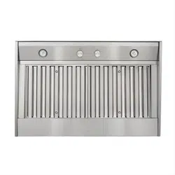
INTERNAL BLOWERS: Insert the house wiring cable through the wire
clamp previously installed in step 8. Tighten the
wire clamp to secure the cable. Connect cable into
wiring box using wire connectors. Connect BLACK
to BLACK, WHITE to WHITE and GREEN or bare
wire under GREEN ground screw. DO NOT
FORGET TO CONNECT THE GROUND. Reinstall
wiring cover.
10. CONNECT THE WIRING
WARNING
Risk of electric shock. Electrical wiring must be done by qualified personnel in accordance with all
applicable codes and standards. Before connecting wires, switch power off at service panel and lock
service disconnecting means to prevent power from being switched on accidentally.
VQ0010
!
HE0059
Position the hood liner below the installed custom hood.
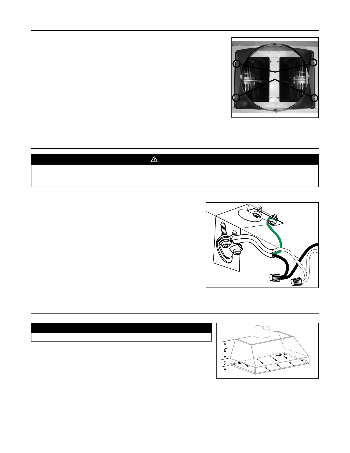
11. INSTALL THE POWER PACK
Using provided screws, install the hood liner inside the custom hood. Start with 2
screws on front corners, then use 4 screws for sides and use the remaining
screws to finalize securing the front hood liner. (See figure at right for mounting
screw specific locations.)
Make sure the adapter/damper (or the adapter) enters the ducting. When there is
access to the top of the hood liner, seal connections with metal foil duct tape.
CAUTION
Take care not to kink ducting when installing the power pack.
Loading ...
Loading ...
Loading ...