
Loading ...
Loading ...
Loading ...
23D-Link DGS-1016D/DGS-1024D User Manual
Section 3 - Hardware Installation
Step 4 – Grounding the Switch
This section describes how to connect the DGS-1016D/DGS-1024D Switch to ground. Completion of this step is strongly advised
for added protection from over voltage and over current from lightning strikes.
Required Tools and Equipment
• Ground screws (included in the accessory kit): One M4 x 6 mm (metric) pan-head screw
• Ground cable (not included in the accessory kit): The grounding cable should be sized according to local and national
installation requirements. Depending on the power supply and system, a 12 to 6 AWG copper conductor is required for
U.S installation. Commercially available 6 AWG wire is recommended. The length of the cable depends on the proximity
of the switch to proper grounding facilities. A #8 terminal lug ring should be fastened to the grounding wire.
• A screwdriver (not included in the accessory kit)
Use the following steps to connect the switch to a protective ground:
1. Verify system is powered o.
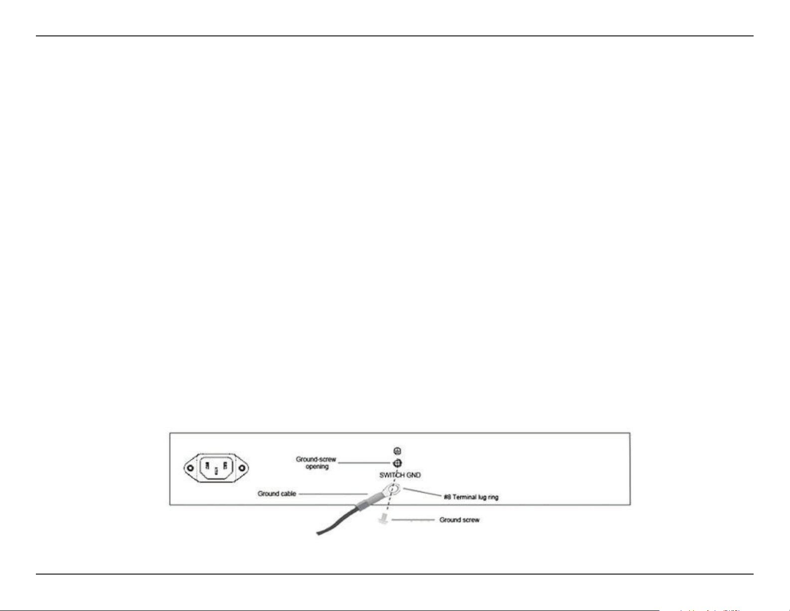
2. Use the ground cable to place the #8 terminal lug ring on top of the ground-screw opening, as seen in the illustration below.
3. Insert the ground screw into the ground-screw opening.
4. Using a screwdriver, tighten the ground screw to secure the ground cable to the switch.
5. Attach the terminal lug ring at the other end of the grounding cable to an appropriate grounding stud or bolt on rack where
the switch is installed.
6. Verify that the connections to the ground connector on the switch and to the rack are securely attached.
Ground cable, screw and #8 terminal lug rings
Loading ...
Loading ...
Loading ...