
Loading ...
Loading ...
Loading ...
Clean Air Filter
The condition of the air filter is important to the operation
of the unit. A dirty air filter will restrict air flow. This is
often mistaken for an out of adjustment carburetor.
Check the condition of the air filter before adjusting the
idle speed screw. Refer to Air Filter Maintenance.
Adjust Idle Speed Screw
_, ARNING: The cutting attachment may spin
during idle speed adjustments. Wear
protective clothing and observe all safety
instructions to prevent serious personal injury. I
If. after checking the fuel and cleaning the air filter, the
engine still will not idle. adJUStthe idle speed screw as
follows:
1. Start the engine and let it run at a high idle for a minute
to warm up. Refer to Starting/Stoppin 9 Instructions
2.
Release the throttle trigger and let the engine idle. If the
engine stops inserta small phillips or fiat blade screwdriver
into the hole in the air filter/muffler cover (Fig. 40). Turn
the idle speed screw in.clockwise 1/8 of a turn at a
time las neededJuntil the engine idles smoothly.
NOTE: The cutting attachment should not rotate when
[he engine idles.
3. If the cutting attachment rotates when the engine idles.
turnthe idle speed screw counterclockwise 1/8 of a
[urn a[ a time [as needed), to reduce idle speed.
Checking the fuel. cleantng the air filter, and adJUSting
the idle speed should solve most engine problems. If not
and all of the following are true:
• the engine will not idle
• the engine hesitates or stalls on acceleration
• there is a loss of engine power
Have the carburetor adjusted by an authorized service dealer.
ROCKER ARM CLEARANCE
This requires disassembly of the engine. If you feel
unsure or unqualified to perform this, take the unit to an
authorized service center.
NOTE: Inspect the valve to rocker arm clearance with a
feeler gauge after the first 10 hours of operation
and then every 25 hours of operation thereafter.
• The engine must be cold when checking or adjusting
the valve clearance.
1.
This task should be performed inside, in a clean,
dust free area.
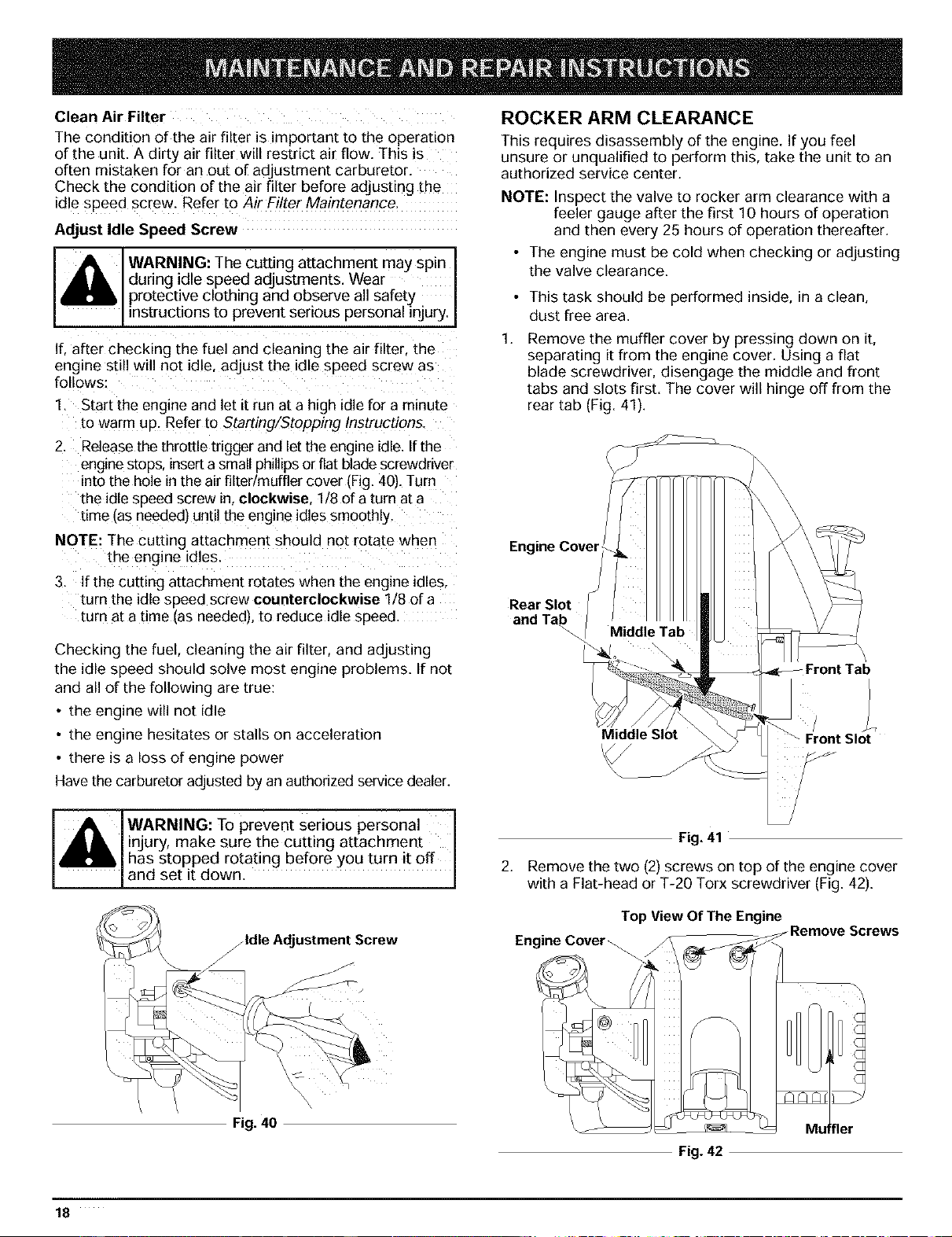
Remove the muffler cover by pressing down on it,
separating it from the engine cover. Using a flat
blade screwdriver, disengage the middle and front
tabs and slots first. The cover will hinge off from the
rear tab (Fig. 41).
Engine Cover
Rear Slot
and Tab
/
\ Front Slot
_1_ fWARNING: To prevent Serious personal I
A_" |injury, make sure the cutting attachment I
ml_m,|has stopped rotating before you turn it off I
[and set it down. I
Fig. 41
2. Remove the two (2) screws on top of the engine cover
with a Flat-head or T-20 Torx screwdriver (Fig. 42).
/Idle Adjustment Screw
Top View Of The Engine
Engine Cover
Fig. 40
Fig. 42
18
Loading ...
Loading ...
Loading ...