Loading ...
Loading ...
Loading ...

6
Unpacking
Upon receiving the pump, it should be
inspected for damage or shortages.
If damage has occurred, fi le a claim
immediately with the carrier that
delivered the pump. If the manual is
removed from the packaging, do not
lose or misplace.
Storage
Short Term - Pumps are
manufactured for effi cient
performance following short
inoperative periods in storage. For
best results, pumps can be retained
in storage, as factory assembled,
in a dry atmosphere with constant
temperatures for up to six (6) months.
Long Term - For storage of six (6)
months, to twenty-four (24) months,
the units should be stored in a
temperature controlled area, a roofed
over walled enclosure that
provides protection from the elements
(rain, snow, wind-blown dust, etc.),
and whose temperature can be
maintained between +40° F and
+120° F. If extended high humidity is
expected to be a problem, all exposed
parts should be inspected before
storage and all surfaces that have the
paint scratched, damaged, or worn
should be recoated with a water base,
air dry enamel paint. All surfaces
should then be sprayed with a rust-in-
hibiting oil.
Pump should be stored in its
original shipping container. On initial
start up, rotate impeller by hand to
assure seal and impeller rotate freely.
If it is required that the pump be
in-stalled and tested before the long
term storage begins, such installation
will be allowed provided:
1. The pump is not installed under
water for more than one (1) month.
2. Immediately upon satisfactory
completion of the test, the pump is
removed, thoroughly dried,
repacked in the original shipping
container, and placed in a
temperature controlled storage
area.
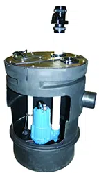
Installation
The basin should be located at the
lowest point in the basement (or
bottom fl oor) below fl oor level. The
bottom of the basin should be level for
proper pump operation.
Install 4” PVC schedule 40 Infl ow pipe
(supplied by contractor) into fl exible
pipe fi tting. The recommended level
should not drop below the top of the
motor housing. Finish connecting
discharge piping and vent piping.
Level Controls
Figure 4 shows a typical installation
for a level control mounted to the
discharge piping with a piggy-back
plug.
Never work in the sump with
the power ON.
1. Level controls are factory set for
a pumping differential of 9”. If
that is the cycle desired, simply
circle the discharge pipe with the
pipe mounting strap, feed the end
through and tighten. Be certain that
the level control can not hang up or
foul in it’s swing.
2. If a higher pump differential is
needed, grip the cord near the
neck of the fl oat, then using the
other hand, exert a steady force on
the lower edge of the cable clamp.
The cable clamp should slide up to
the new pivot point.
Automatic - Plug fl oat cord into
outlet, then plug pump cord into fl oat
cord.
Manual - Plug pump cord directly into
outlet.
Loading ...
Loading ...
Loading ...