Loading ...
Loading ...
Loading ...
®
®
®
®
®
®
3
USER GUIDE
ZC Series Wall Controllers
IN
OUT
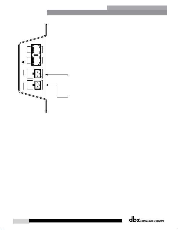
INPUTS
RJ45 - CONNECT ONLY TO
ZONE CONTROLLER INPUT
RELAY/
SWITCH
CLOSURE
CONTROL
VOLTAGE
5-24 VDC
Connect a normally open or normally closed relay closure
to this connector.
Connect a 5-24V DC control voltage to this connector.
Or
ZC-FIRE
Diagram E
Zone Controller Maximum Cable Length
Note - The following cable lengths were achieved using Cat5 Enhanced cable exhibiting a maximum D.C.
resistance of 29 Ohms per 1,000 feet. When connecting Zone Controllers in series, the following cable length
restrictions apply:
• As shown in Diagram F, any (3) Zone Controllers may be wired in series as long as the total cable
length does not exceed 600 feet.
• Any (6) Zone Controllers may be wired in series as long as the total cable length does not exceed 300
feet. Refer to Diagram G.
• Cable runs of up to 1,000 feet may be achieved using “Home Run” wiring. An example of this is
shown in Diagram H. A dbx Zone Controller Break Out Box (dbx ZC-BOB) is used to parallel several
cable runs. It should be noted that a 1,000 foot cable with a single Zone Controller may be connected
directly to the controlled device.
Note - Daisy chaining Zone Controllers to a ZC-BOB (connecting them serially) is not supported or
recommended.
Loading ...
Loading ...
Loading ...