Loading ...
Loading ...
Loading ...
PIPING INSTALLATION
4. Trim centering guides if necessary. Centering guides will
fit 6 inch or larger well casings and 1 inch drop pipe. For
4 or 5 inch casings, the outside tabs must be trimmed with
a hacksaw or knife. See marks on tabs. For drop pipe sizes
1-1/4 and 1-1/2 inch, inside hole of guide must be
trimmed. See marks on guide. NOTE: Do not cut hole
oversize. A snug fit works best.
5. Slide centering guides on the plastic pipe. First guide
should be located about 6 inches above the pump dis-
charge connection. Additional guides should be located
at equal intervals on the plastic pipe.
After placing first guide about 6 inches above the dis-
charge connection, place a stainless steel hose clamp
above the guide. This will prevent guide from sliding up
pipe as pump is lowered in well. On other guides, place
clamp above and below it to maintain position.
6. Slide plastic pipe on to the nylon adapter until it is up to
the shoulder on the adapter. Clamp pipe to adapter with
2 stainless steel hose clamps. Place the screw mechanisms
on clamps opposite each other. Tape down excess length
of hose clamp band.
7. Feed motor leads through the first centering guide. Make
electric cable splices according to choices on Pages 7 and
8. Stagger the splices by cutting one lead about 4 inches
longer than the other one. Tape splices to the plastic pipe.
Note that staggering prevents the splices from rubbing on
the well casing.
8. Unroll the balance of the electrical cable along side of
plastic pipe. Be sure not to damage the insulation or kink
the wire. Now go back and feed the cable through the
centering guides located along the pipe.
9. If necessary, cut plastic pipe shorter than proper depth
setting to allow for bleeder orifice piping assembly or dis-
tance down to your pitless adapter.
10. ffa standard pressure tank system is being used, make up
bleeder orifice assembly as shown in installation draw-
ings (Figure 1, Page 4). Using teflon tape on all male
threads. Assemble this unit to the plastic pipe in same
manner as outlined in Step 6.
I"x CAUTION] Assembly may slip through well seal.
Install an elbow on the pipe above the well seat. This
safety measure will prevent dropping the pipe and pump
into the well when lowering it.
11. ff a Captive Air@ pressure tank system is being used, as-
semble as shown in the typical pump installation with
Captive Air@ Tank (Figure 1, Page 4). Note that bleeder
orifices and check valves are not used.
12. ff well seal is used, assemble safety ring in bottom part of
the seal.
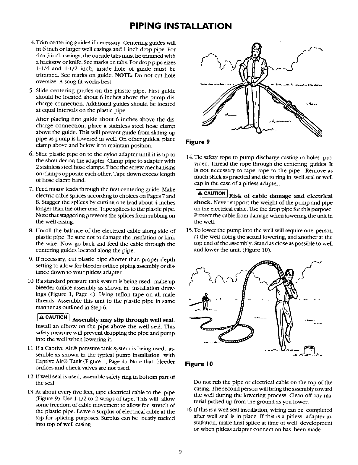
13.At about every five feet, tape electrical cable to the pipe
(Figure 9). Use 1-1/2 to 2 wraps of tape. This will allow
some freedom of cable movement to allow for stretch of
the plastic pipe. Leave a surplus of electrical cable at the
top for splicing purposes. Surplus can be neatly rocked
into top of well casing.
Figure 9
14.Tie safety rope to pump discharge casting in holes pro-
vided. Thread the rope through the centering guides. It
is not necessary to tape rope to the pipe. Remove as
ranch slack as practical and tie to ring in well seal or well
cap in the case of a pidess adapter.
I& CAUTION ]Risk of cable damage and electrical
shock. Never support the weight of the pump and pipe
on the electrical cable. Use the drop pipe for this purpose.
Protect the cable from damage when lowering the unit in
the well.
15. To lower the pump into the well will require one person
at the well doing the actual lowering, and another at the
top end of the assembly. Stand as close as possible to well
and lower the unit. (Figure 10).
Figure I 0
Do not rub the pipe or electrical cable on the top of the
casing. The second person will bring the assembly toward
the well during the lowering process. Clean off any ma-
terial picked up from the ground as you lower.
16.If this is a well seal installation, wiring can be completed
after well seal is in place. If this is a pidess adapter in-
stallation, make final splice at time of well development
or when pittess adapter connection has been made.
9
Loading ...
Loading ...
Loading ...