
1
2
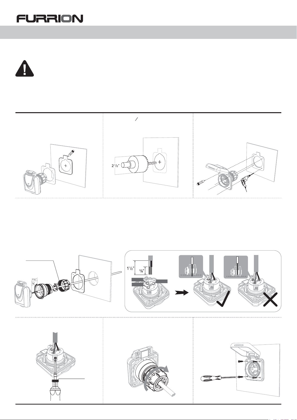
2. Using a 2
”
hole saw, cut out the
centre circular hole.
Installation Instructions
30Amp Shore Power Inlet
WARNING
ELECTRICAL SHOCK AND FIRE HAZARD!
To prevent the risk of electrocution or fire, ensure the inlet and connecting cables are NOT connected to a power source
during installation!
Use only 10 AWG or above cable with this product. Using a smaller AWG cable will result in overheating and possible Fire
Hazard.
Cable color scheme for 125V 3 core connection to inlet.
Black = X - Live/Hot Cable White = W - Neutral Cable Green = G - Ground Cable
14-16 in-lbs
1. Determine the mounting position of
your power inlet and using the sealing
gasket included with your 30 Amp inlet,
mark a basic outline of the gasket and the
centre of the inside circle.
3. Place your Inlet in the new opening and
mark the mounting screw/bolt hole positions.
4. Remove the Inlet from the opening and
using a 1/8
”
drill bit, drill the mounting
screw/bolt holes.
11. Tighten terminal screws to 14-16 in-lbs
torque.
13. Align the gasket and inlet in the
opening, fix the inlet with stainless
screws/bolts to the mounting surface.
12. Slide the rear cover over the terminal
connection and seat the locking feet,
turn the rear cover clockwise to lock into
position.
5. Feed the internal 10 AWG cable through the new opening.
6. Remove the rear cable strain relief cover from the inlet .
7. Thread the cable through the sealing gasket.
8. Thread the power cable through the cable strain opening on the back cover.
9. Strip off 1½
”
of the outer insulation layer of your cable.
10. Strip off 5/8
”
of colored insulation from the ends of your 3 conductor cables, making sure you strip back to new wire without
corrosion. Connect the colored wires to the corresponding lettered holes on the back of the inlet, (see above for color to letter markings)
taking care not to have any stray wire strands, or have insulation pushed inside the terminal holes
White
Black
Green
IM-F30ITX-V1
Cable length: 6-8”
1
/8” drill bit
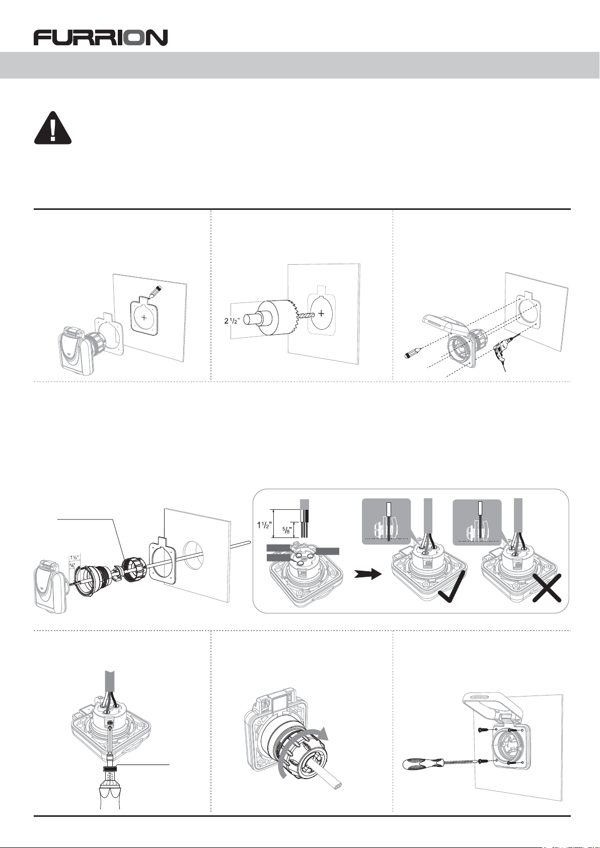
ATTENTION, RISQUES D’ELECTROCUTION ET D’INCENDIES !
Afin de prévenir tous risques d’électrocution ou d’incendie, s’assurer que la fiche et les câbles de connexion ne soient pas
raccordés au réseau pendant l’installation!
N’utiliser que du câble de type AWG10 ou supérieur avec ce produit. Une section de câble trop fine peut engendrer une
surchauffe et un risque d’incendie.
Le code couleur pour du câble 3 brins 125V est le suivant:
Noir (X) = X - tension réseau/service Blanc (W) = W - neutre Vert (G) = G - masse
Installation de votre fiche
FURRION 30 ampères
14-16 in-lbs
1. A l’aide du joint d’étanchéité inclus avec
votre fiche FURRION 30 ampères,
déterminer la position de montage en
faisant un marquage au crayon du contour
du joint ainsi que le centre du cercle.
3. Placer votre fiche FURRION dans la
découpe et marquer les points de repère
pour les vis.
4. Enlever la fiche puis percer le trou des
vis à l’aide d’un foret de 1/8”.
2. Faire un trou au centre du cercle, puis
à l’aide d’une scie, débiter le cercle
13. Aligner le joint d’étanchéité avec la
fiche dans l’ouverture pratiquée
précédemment, puis monter la fiche à
l’aide des vis fournies.
12. Glisser le capot arrière sur les
bornes et les pieds verrouillage de
siège, tournez le couvercle arrière à
verrouillage en position.
5. Passer le câble AWG10 dans la découpe
6. Enlever le capot pour le maintien/serrage du câble
7. Passer le câble au travers du joint d’étanchéité
8. Passer le câble de puissance à travers l’ouverture prévu à cet effet
9. Retirer 1½” d’isolant au bout de votre câble
10. Retirer 5/8” d’isolant au bout de votre câble 3 brins en vérifiant qu’il n’y a pas de corrosion. Connecter les 3 brins en repérant la
correspondance avec les lettres sur l’arrière de votre fiche (cf. plus haut pour le code couleur). Vérifier qu’il n’y a pas d’isolant dans
les trous prévus pour le passage du câble
11. Serrer les vis pour le maintien des
câbles avec une lame de couple conduc-
teur (couple recommandé: 14-16 in-lbs) (Ne
pas utiliser un tournevis pneuma-
tique ou électrique du
conducteur lors du serrage
des terminaux)
White
Black
Green
Cable length: 6-8”
1
/8” drill bit
IM-F30ITX-V1