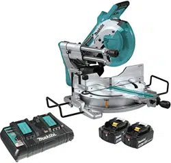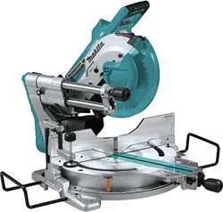
INSTRUCTION MANUAL
Slide Compound Miter Saw
LS1019
LS1019L
ENGLISH: Original instructions
DOUBLE INSULATION
Read before use.

2 ENGLISH
SPECIFICATIONS
Model: LS1019 LS1019L
Blade diameter European countries 260 mm
Countries other than Europe 255 mm - 260 mm
Hole diameter European countries 30 mm
Countries other than Europe 25.4 mm
Max. kerf thickness of the saw blade 3.2 mm
Max. miter angle Right 60°, Left 60°
Max. bevel angle Right 48°, Left 48°
No load speed (RPM) 3,200 min
-1
Laser type -
Red Laser 650 nm, Maximum output
1.6mW ( Laser Class 2M )
Dimensions (L x W x H) 805 mm x 644 mm x 660 mm
Net weight 26.1 kg 26.3 kg
Cutting capacities (H x W)
Miter angle Bevel angle
45° (left) 0° 45° (right)
0° 42 mm x 310 mm
58 mm x 279mm
68 mm x 310 mm
91 mm x 279 mm
29 mm x 310 mm
43 mm x 279 mm
45° (right and left) 42 mm x 218 mm
58 mm x 197 mm
68 mm x 218 mm
91 mm x 197 mm
29 mm x 218 mm
43 mm x 197 mm
60° (right and left) - 68 mm x 155 mm
91 mm x 139 mm
-
Cutting capacities for special cuttings
Type of cutting Cutting capacity
Crown molding 45° type
(with crown molding stopper used)
168 mm
Base board
(with horizontal vise used)
133 mm
•
Due to our continuing program of research and development, the specications herein are subject to change without notice.
• Specications may differ from country to country.
• Weight according to EPTA-Procedure 01/2014
Symbols
The followings show the symbols used for the equip-
ment. Be sure that you understand their meaning before
use.
Read instruction manual.
DOUBLE INSULATION
To avoid injury from ying debris, keep
holding the saw head down, after making
cuts, until the blade has come to a com-
plete stop.
1
2
3
When performing bevel cut, rst turn the
knob counterclockwise and then tilt the
carriage. After that, turn the knob clockwise
to tighten.
When performing slide cut, rst pull car-
riage fully and press down handle, then
push carriage toward the guide fence.
Hold down the releasing button when tilting
the carriage to the right.
Engage the stopper lever when cutting a
base board in 45° miter angle.
Do not place hand or ngers close to the
blade.
Never look into the laser beam. Direct laser
beam may injure your eyes.
Do not install the horizontal vise to the
same direction as the miter cutting. (This
symbol is applied on the horizontal vise)
Only for EU countries
Do not dispose of electric equipment together
with household waste material! In observance of
the European Directive, on Waste Electric and
Electronic Equipment and its implementation
in accordance with national law, electric equip-
ment that have reached the end of their life
must be collected separately and returned to an
environmentally compatible recycling facility.

3 ENGLISH
Intended use
The tool is intended for accurate straight and miter
cutting in wood. With appropriate saw blades, aluminum
can also be sawed.
Power supply
The tool should be connected only to a power supply of
the same voltage as indicated on the nameplate, and
can only be operated on single-phase AC supply. They
are double-insulated and can, therefore, also be used
from sockets without earth wire.
Noise
The typical A-weighted noise level determined accord-
ing to EN62841-3-9:
Model LS1019
Sound pressure level (L
pA
) : 91 dB(A)
Sound power level (L
WA
) : 101 dB (A)
Uncertainty (K) : 3 dB(A)
Model LS1019L
Sound pressure level (L
pA
) : 91 dB(A)
Sound power level (L
WA
) : 101 dB (A)
Uncertainty (K) : 3 dB(A)
NOTE: The declared noise emission value(s) has
been measured in accordance with a standard test
method and may be used for comparing one tool with
another.
NOTE: The declared noise emission value(s)
may also be used in a preliminary assessment of
exposure.
WARNING: Wear ear protection.
WARNING: The noise emission during actual
use of the power tool can differ from the declared
value(s) depending on the ways in which the
tool is used especially what kind of workpiece is
processed.
WARNING: Be sure to identify safety mea-
sures to protect the operator that are based on an
estimation of exposure in the actual conditions of
use (taking account of all parts of the operating
cycle such as the times when the tool is switched
off and when it is running idle in addition to the
trigger time).
Vibration
The vibration total value (tri-axial vector sum) deter-
mined according to EN62841-3-9:
Model LS1019
Vibration emission (a
h
) : 2.5 m/s
2
or less
Uncertainty (K) : 1.5 m/s
2
Model LS1019L
Vibration emission (a
h
) : 2.5 m/s
2
or less
Uncertainty (K) : 1.5 m/s
2
NOTE: The declared vibration total value(s) has been
measured in accordance with a standard test method
and may be used for comparing one tool with another.
NOTE: The declared vibration total value(s) may also
be used in a preliminary assessment of exposure.
WARNING:
The vibration emission during actual
use of the power tool can differ from the declared val-
ue(s) depending on the ways in which the tool is used
especially what kind of workpiece is processed.
WARNING:
Be sure to identify safety measures
to protect the operator that are based on an estima-
tion of exposure in the actual conditions of use (tak-
ing account of all parts of the operating cycle such
as the times when the tool is switched off and when
it is running idle in addition to the trigger time).
EC Declaration of Conformity
For European countries only
The EC declaration of conformity is included as Annex A
to this instruction manual.
SAFETY WARNINGS
General power tool safety warnings
WARNING: Read all safety warnings, instruc-
tions, illustrations and specications provided
with this power tool. Failure to follow all instructions
listed below may result in electric shock, re and/or
serious injury.
Save all warnings and instruc-
tions for future reference.
The term "power tool" in the warnings refers to your mains-oper-
ated (corded) power tool or battery-operated (cordless) power tool.
Work area safety
1. Keep work area clean and well lit. Cluttered or
dark areas invite accidents.
2. Do not operate power tools in explosive atmo-
spheres, such as in the presence of ammable
liquids, gases or dust. Power tools create sparks
which may ignite the dust or fumes.
3. Keep children and bystanders away while
operating a power tool. Distractions can cause
you to lose control.
Electrical safety
1. Power tool plugs must match the outlet. Never
modify the plug in any way. Do not use any
adapter plugs with earthed (grounded) power
tools. Unmodied plugs and matching outlets will
reduce risk of electric shock.
2. Avoid body contact with earthed or grounded
surfaces, such as pipes, radiators, ranges and
refrigerators. There is an increased risk of elec-
tric shock if your body is earthed or grounded.
3. Do not expose power tools to rain or wet con-
ditions. Water entering a power tool will increase
the risk of electric shock.
4. Do not abuse the cord. Never use the cord for
carrying, pulling or unplugging the power tool.
Keep cord away from heat, oil, sharp edges
or moving parts. Damaged or entangled cords
increase the risk of electric shock.

4 ENGLISH
5. When operating a power tool outdoors, use an
extension cord suitable for outdoor use. Use of
a cord suitable for outdoor use reduces the risk of
electric shock.
6. If operating a power tool in a damp location
is unavoidable, use a residual current device
(RCD) protected supply. Use of an RCD reduces
the risk of electric shock.
7. Use of power supply via an RCD with a rated
residual current of 30 mA or less is always
recommended.
8.
Power tools can produce electromagnetic elds
(EMF) that are not harmful to the user. However,
users of pacemakers and other similar medical
devices should contact the maker of their device and/
or doctor for advice before operating this power tool.
9. Do not touch the power plug with wet hands.
10. If the cord is damaged, have it replaced by the
manufacturer or his agent in order to avoid a
safety hazard.
Personal safety
1. Stay alert, watch what you are doing and use
common sense when operating a power tool.
Do not use a power tool while you are tired or
under the inuence of drugs, alcohol or med-
ication. A moment of inattention while operating
power tools may result in serious personal injury.
2. Use personal protective equipment. Always
wear eye protection. Protective equipment such
as a dust mask, non-skid safety shoes, hard hat or
hearing protection used for appropriate conditions
will reduce personal injuries.
3. Prevent unintentional starting. Ensure the
switch is in the off-position before connecting
to power source and/or battery pack, picking
up or carrying the tool. Carrying power tools with
your nger on the switch or energising power tools
that have the switch on invites accidents.
4. Remove any adjusting key or wrench before
turning the power tool on. A wrench or a key left
attached to a rotating part of the power tool may
result in personal injury.
5. Do not overreach. Keep proper footing and
balance at all times. This enables better control
of the power tool in unexpected situations.
6. Dress properly. Do not wear loose clothing or
jewellery. Keep your hair and clothing away
from moving parts. Loose clothes, jewellery or
long hair can be caught in moving parts.
7. If devices are provided for the connection of
dust extraction and collection facilities, ensure
these are connected and properly used. Use of
dust collection can reduce dust-related hazards.
8.
Do not let familiarity gained from frequent use
of tools allow you to become complacent and
ignore tool safety principles. A careless action can
cause severe injury within a fraction of a second.
9. Always wear protective goggles to protect
your eyes from injury when using power tools.
The goggles must comply with ANSI Z87.1 in
the USA, EN 166 in Europe, or AS/NZS 1336
in Australia/New Zealand. In Australia/New
Zealand, it is legally required to wear a face
shield to protect your face, too.
It is an employer's responsibility to enforce
the use of appropriate safety protective equip-
ments by the tool operators and by other per-
sons in the immediate working area.
Power tool use and care
1. Do not force the power tool. Use the correct
power tool for your application. The correct
power tool will do the job better and safer at the
rate for which it was designed.
2. Do not use the power tool if the switch does
not turn it on and off. Any power tool that cannot
be controlled with the switch is dangerous and
must be repaired.
3. Disconnect the plug from the power source
and/or remove the battery pack, if detachable,
from the power tool before making any adjust-
ments, changing accessories, or storing power
tools. Such preventive safety measures reduce
the risk of starting the power tool accidentally.
4. Store idle power tools out of the reach of chil-
dren and do not allow persons unfamiliar with
the power tool or these instructions to operate
the power tool. Power tools are dangerous in the
hands of untrained users.
5. Maintain power tools and accessories. Check
for misalignment or binding of moving parts,
breakage of parts and any other condition that
may affect the power tool’s operation. If dam-
aged, have the power tool repaired before use.
Many accidents are caused by poorly maintained
power tools.
6. Keep cutting tools sharp and clean. Properly
maintained cutting tools with sharp cutting edges
are less likely to bind and are easier to control.
7. Use the power tool, accessories and tool bits
etc. in accordance with these instructions, tak-
ing into account the working conditions and
the work to be performed. Use of the power tool
for operations different from those intended could
result in a hazardous situation.
8. Keep handles and grasping surfaces dry,
clean and free from oil and grease. Slippery
handles and grasping surfaces do not allow for
safe handling and control of the tool in unexpected
situations.
9. When using the tool, do not wear cloth work
gloves which may be entangled. The entangle-
ment of cloth work gloves in the moving parts may
result in personal injury.

5 ENGLISH
Service
1. Have your power tool serviced by a qualied
repair person using only identical replacement
parts. This will ensure that the safety of the power
tool is maintained.
2. Follow instruction for lubricating and chang-
ing accessories.
Safety instructions for mitre saws
1. Mitre saws are intended to cut wood or wood-
like products, they cannot be used with abra-
sive cut-off wheels for cutting ferrous material
such as bars, rods, studs, etc. Abrasive dust
causes moving parts such as the lower guard to
jam. Sparks from abrasive cutting will burn the
lower guard, the kerf insert and other plastic parts.
2. Use clamps to support the workpiece when-
ever possible. If supporting the workpiece
by hand, you must always keep your hand at
least 100 mm from either side of the saw blade.
Do not use this saw to cut pieces that are too
small to be securely clamped or held by hand.
If your hand is placed too close to the saw blade,
there is an increased risk of injury from blade
contact.
3. The workpiece must be stationary and
clamped or held against both the fence and the
table. Do not feed the workpiece into the blade
or cut "freehand" in any way. Unrestrained
or moving workpieces could be thrown at high
speeds, causing injury.
4. Push the saw through the workpiece. Do not
pull the saw through the workpiece. To make
a cut, raise the saw head and pull it out over
the workpiece without cutting, start the motor,
press the saw head down and push the saw
through the workpiece. Cutting on the pull stroke
is likely to cause the saw blade to climb on top
of the workpiece and violently throw the blade
assembly towards the operator.
5. Never cross your hand over the intended line
of cutting either in front or behind the saw
blade. Supporting the workpiece "cross handed"
i.e. holding the workpiece to the right of the saw
blade with your left hand or vice versa is very
dangerous.
6. Do not reach behind the fence with either hand
closer than 100 mm from either side of the saw
blade, to remove wood scraps, or for any other
reason while the blade is spinning. The proxim-
ity of the spinning saw blade to your hand may not
be obvious and you may be seriously injured.
7. Inspect your workpiece before cutting. If the
workpiece is bowed or warped, clamp it with
the outside bowed face toward the fence.
Always make certain that there is no gap
between the workpiece, fence and table along
the line of the cut. Bent or warped workpieces
can twist or shift and may cause binding on the
spinning saw blade while cutting. There should be
no nails or foreign objects in the workpiece.
8. Do not use the saw until the table is clear of all
tools, wood scraps, etc., except for the work-
piece. Small debris or loose pieces of wood or
other objects that contact the revolving blade can
be thrown with high speed.
9. Cut only one workpiece at a time. Stacked multi-
ple workpieces cannot be adequately clamped or
braced and may bind on the blade or shift during
cutting.
10. Ensure the mitre saw is mounted or placed on
a level, rm work surface before use. A level
and rm work surface reduces the risk of the mitre
saw becoming unstable.
11. Plan your work. Every time you change the
bevel or mitre angle setting, make sure the
adjustable fence is set correctly to support the
workpiece and will not interfere with the blade
or the guarding system. Without turning the tool
"ON" and with no workpiece on the table, move
the saw blade through a complete simulated cut to
assure there will be no interference or danger of
cutting the fence.
12. Provide adequate support such as table exten-
sions, saw horses, etc. for a workpiece that is
wider or longer than the table top. Workpieces
longer or wider than the mitre saw table can tip
if not securely supported. If the cut-off piece or
workpiece tips, it can lift the lower guard or be
thrown by the spinning blade.
13. Do not use another person as a substitute for
a table extension or as additional support.
Unstable support for the workpiece can cause the
blade to bind or the workpiece to shift during the
cutting operation pulling you and the helper into
the spinning blade.
14. The cut-off piece must not be jammed or
pressed by any means against the spinning
saw blade. If conned, i.e. using length stops, the
cut-off piece could get wedged against the blade
and thrown violently.
15. Always use a clamp or a xture designed to
properly support round material such as rods
or tubing. Rods have a tendency to roll while
being cut, causing the blade to "bite" and pull the
work with your hand into the blade.
16. Let the blade reach full speed before contact-
ing the workpiece. This will reduce the risk of the
workpiece being thrown.

6 ENGLISH
17. If the workpiece or blade becomes jammed,
turn the mitre saw off. Wait for all moving
parts to stop and disconnect the plug from
the power source and/or remove the battery
pack. Then work to free the jammed material.
Continued sawing with a jammed workpiece could
cause loss of control or damage to the mitre saw.
18. After nishing the cut, release the switch,
hold the saw head down and wait for the blade
to stop before removing the cut-off piece.
Reaching with your hand near the coasting blade
is dangerous.
19. Hold the handle rmly when making an incom-
plete cut or when releasing the switch before
the saw head is completely in the down posi-
tion. The braking action of the saw may cause
the saw head to be suddenly pulled downward,
causing a risk of injury.
20. Only use the saw blade with the diameter that
is marked on the tool or specied in the man-
ual. Use of an incorrectly sized blade may affect
the proper guarding of the blade or guard opera-
tion which could result in serious personal injury.
21. Only use the saw blades that are marked with
a speed equal or higher than the speed marked
on the tool.
22. Do not use the saw to cut other than wood,
aluminum or similar materials.
23. (For European countries only)
Always use the blade which conforms to
EN847-1.
Additional instructions
1. Make workshop kid proof with padlocks.
2. Never stand on the tool. Serious injury could
occur if the tool is tipped or if the cutting tool is
unintentionally contacted.
3. Never leave the tool running unattended. Turn
the power off. Do not leave tool until it comes
to a complete stop.
4. Do not operate saw without guards in place.
Check blade guard for proper closing before
each use. Do not operate saw if blade guard
does not move freely and close instantly.
Never clamp or tie the blade guard into the
open position.
5. Keep hands out of path of saw blade. Avoid
contact with any coasting blade. It can still
cause severe injury.
6. To reduce the risk of injury, return carriage
to the full rear position after each crosscut
operation.
7. Always secure all moving portions before
carrying the tool.
8. Stopper pin which locks the cutter head down
is for carrying and storage purposes only and
not for any cutting operations.
9. Check the blade carefully for cracks or dam-
age before operation. Replace cracked or dam-
aged blade immediately. Gum and wood pitch
hardened on blades slows saw and increases
potential for kickback. Keep blade clean by
rst removing it from tool, then cleaning it with
gum and pitch remover, hot water or kerosene.
Never use gasoline to clean blade.
10. While making a slide cut, KICKBACK can
occur. KICKBACK occurs when the blade
binds in the workpiece during a cutting oper-
ation and the saw blade is driven rapidly
towards the operator. Loss of control and seri-
ous personal injury can result. If blade begins
to bind during a cutting operation, do not con-
tinue to cut and release switch immediately.
11. Use only anges specied for this tool.
12. Be careful not to damage the arbor, anges
(especially the installing surface) or bolt.
Damage to these parts could result in blade
breakage.
13. Make sure that the turn base is properly
secured so it will not move during operation.
Use the holes in the base to fasten the saw to a
stable work platform or bench. NEVER use tool
where operator positioning would be awkward.
14. Make sure the shaft lock is released before the
switch is turned on.
15. Be sure that the blade does not contact the
turn base in the lowest position.
16. Hold the handle rmly. Be aware that the saw
moves up or down slightly during start-up and
stopping.
17. Make sure the blade is not contacting the
workpiece before the switch is turned on.
18. Before using the tool on an actual workpiece,
let it run for a while. Watch for vibration or
wobbling that could indicate poor installation
or a poorly balanced blade.
19. Stop operation immediately if you notice any-
thing abnormal.
20. Do not attempt to lock the trigger in the "ON"
position.
21. Always use accessories recommended in this
manual. Use of improper accessories such as
abrasive wheels may cause an injury.
22. Some material contains chemicals which may
be toxic. Take caution to prevent dust inhala-
tion and skin contact. Follow material supplier
safety data.
Additional safety rules for the laser
1. LASER RADIATION, DO NOT STARE INTO THE
BEAM OR VIEW DIRECTLY WITH OPTICAL
INSTRUMENTS, CLASS 2M LASER PRODUCT.
SAVE THESE INSTRUCTIONS.
WARNING: DO NOT let comfort or familiarity
with product (gained from repeated use) replace
strict adherence to safety rules for the subject
product. MISUSE or failure to follow the safety
rules stated in this instruction manual may cause
serious personal injury.
7 ENGLISH
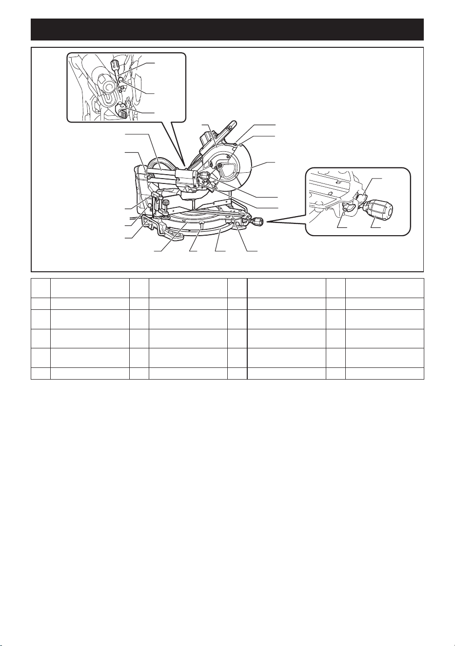
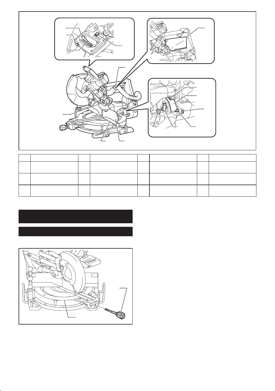
PARTS DESCRIPTION
10 11
12
14
15
3
2
4
5
879
13
6
1
16
17
18
19
20
21
1 Slide pole 2 Stopper pin (for carriage
sliding)
3 Vertical vise 4 Releasing button (for
right side bevel angle)
5 Holder 6 Turn base 7 Pointer (for miter angle) 8 Miter angle scale
9 Kerf board 10 Blade case 11 Adjusting screw (for
laser line)
12 Range adjustment screw
(for laser line)
13 Blade guard 14 Knob (for bevel angle) 15 Hex wrench 16 Adjusting screw (for
lower limit position)
17 Adjusting bolt (for maxi-
mum cutting capacity)
18 Stopper arm 19 Lock lever (for turn base) 20 Releasing lever (for turn
base)
21 Grip (for turn base) - - - - - -
8 ENGLISH
7 8
5
6
1
2
3
4
9
10
11
141312
15
1 Switch trigger 2 Lock-off button 3 Hole for padlock 4 Switch (for laser line)
5 Hose (for dust
extraction)
6 Stopper pin (for carriage
elevation)
7 Guide fence (lower
fence)
8 Guide fence (upper
fence)
9 Dust bag 10 0° adjusting bolt (for
bevel angle)
11 Bevel angle scale 12 Releasing lever (for 48°
bevel angle)
13 Latch lever (for bevel
angle)
14 Pointer (for bevel angle) 15 45° adjusting bolt (for
bevel angle)
- -
INSTALLATION
Installing the grip
Screw the threaded shaft of the grip into the turn base.
1
2
► 1. Grip 2. Turn base
9 ENGLISH
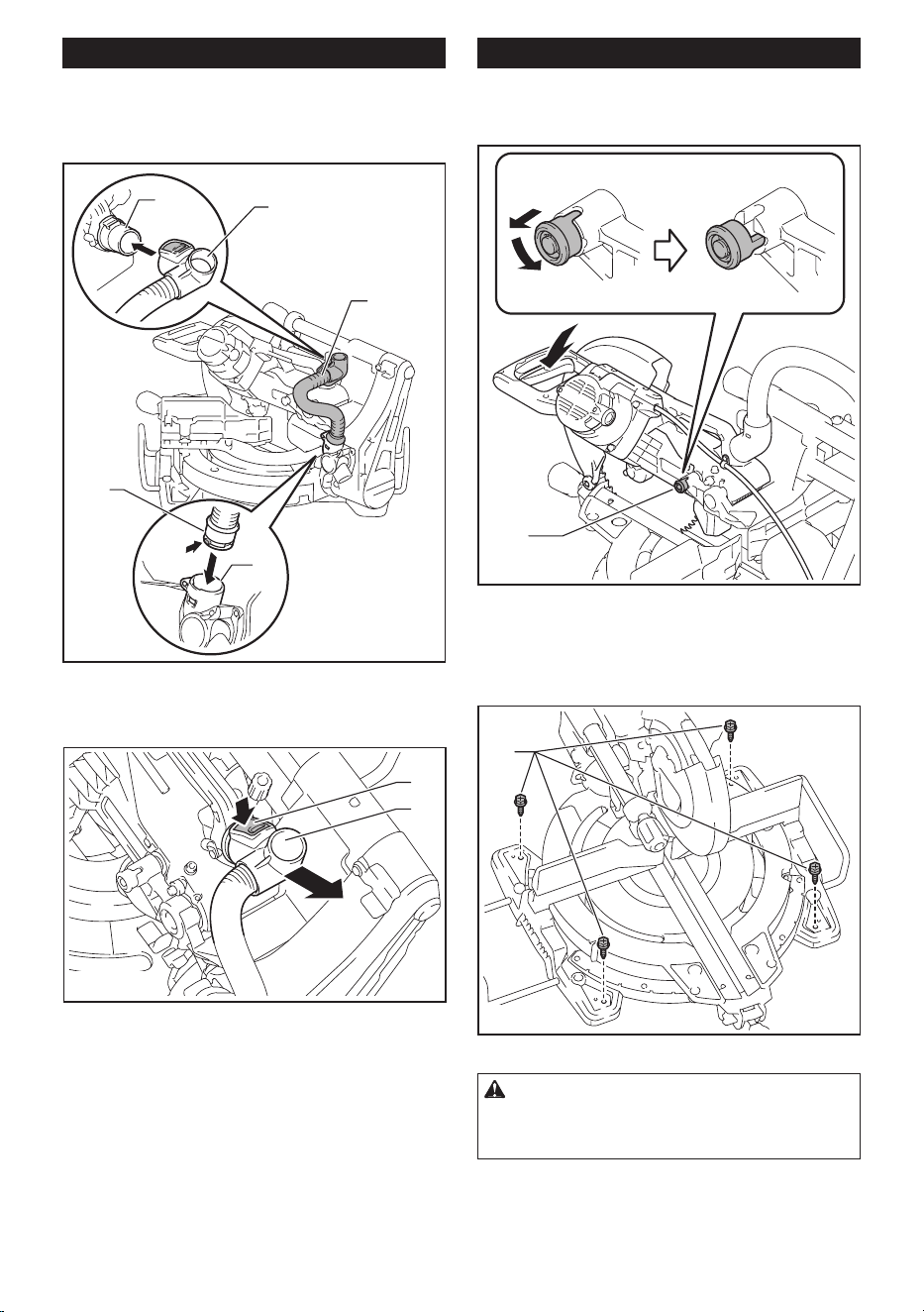
Installing the dust extraction hose
Connect the dust extraction hose to the tool as
illustrated.
Make sure that the elbow and the sleeve t properly to
the ports of the tool.
1
2
3
4
4
► 1. Dust extraction hose 2. Elbow 3. Sleeve 4. Port
To remove the elbow from the port, pull the elbow while
pressing down the lock button.
2
1
► 1. Lock button 2. Elbow
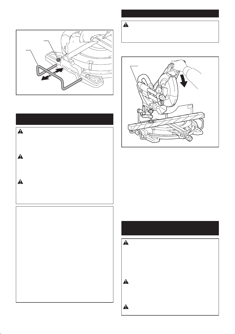
Bench mounting
When the tool is shipped, the handle is locked in the
lowered position by the stopper pin. While lowering the
handle slightly, pull the stopper pin and rotate it 90°.
3
12
► 1. Locked position 2. Unlocked position 3. Stopper
pin
This tool should be bolted with four bolts to a level and
stable surface using the bolt holes provided in the tool's
base. This will help prevent tipping and possible injury.
1
► 1. Bolt
WARNING: Ensure that the tool will not move
on the supporting surface. Movement of the miter
saw on the supporting surface while cutting may
result in loss of control and serious personal injury.
10 ENGLISH
FUNCTIONAL
DESCRIPTION
WARNING: Always be sure that the tool is
switched off and unplugged before adjusting or
checking function on the tool. Failure to switch off
and unplug the tool may result in serious personal
injury from accidental start-up.
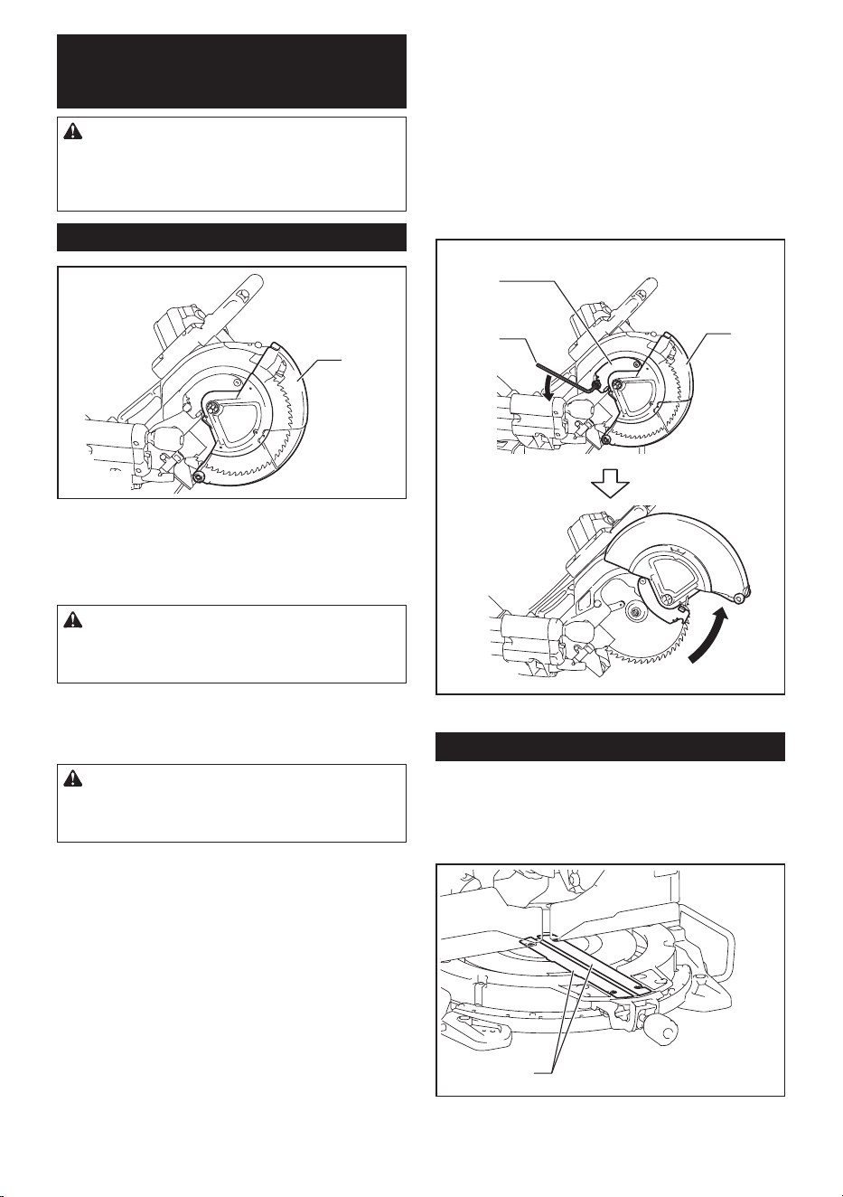
Blade guard
1
► 1. Blade guard
When lowering the handle, the blade guard rises auto-
matically. The guard is spring loaded so it returns to
its original position when the cut is completed and the
handle is raised.
WARNING: Never defeat or remove the blade
guard or the spring which attaches to the guard.
An exposed blade as a result of defeated guarding
may result in serious personal injury during operation.
In the interest of your personal safety, always maintain
the blade guard in good condition. Any irregular opera-
tion of the blade guard should be corrected immediately.
Check to assure spring loaded return action of guard.
WARNING: Never use the tool if the blade
guard or spring are damaged, faulty or removed.
Operation of the tool with a damaged, faulty or
removed guard may result in serious personal injury.
If the see-through blade guard becomes dirty, or saw-
dust adheres to it in such a way that the blade and/or
workpiece is no longer easily visible, unplug the saw
and clean the guard carefully with a damp cloth. Do not
use solvents or any petroleum-based cleaners on the
plastic guard because this may cause damage to the
guard.
If the blade guard is especially dirty and vision through
the guard is impaired, unplug the tool and use the sup-
plied wrench to loosen the hex bolt holding the center
cover. Loosen the hex bolt by turning it counterclock-
wise and raise the blade guard and center cover. With
the blade guard so positioned, cleaning can be more
completely and efciently accomplished. When cleaning
is complete, reverse procedure above and secure bolt.
Do not remove spring holding blade guard. If guard
becomes discolored through age or UV light exposure,
contact a Makita service center for a new guard. DO
NOT DEFEAT OR REMOVE GUARD.
3
1
2
► 1. Center cover 2. Hex wrench 3. Blade guard
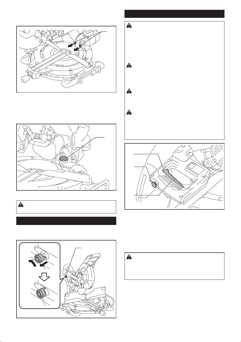
Kerf boards
This tool is provided with the kerf boards in the turn
base to minimize tearing on the exit side of a cut. The
kerf boards are factory adjusted so that the saw blade
does not contact the kerf boards. Before use, adjust the
kerf boards as follows:
1
► 1. Kerf board
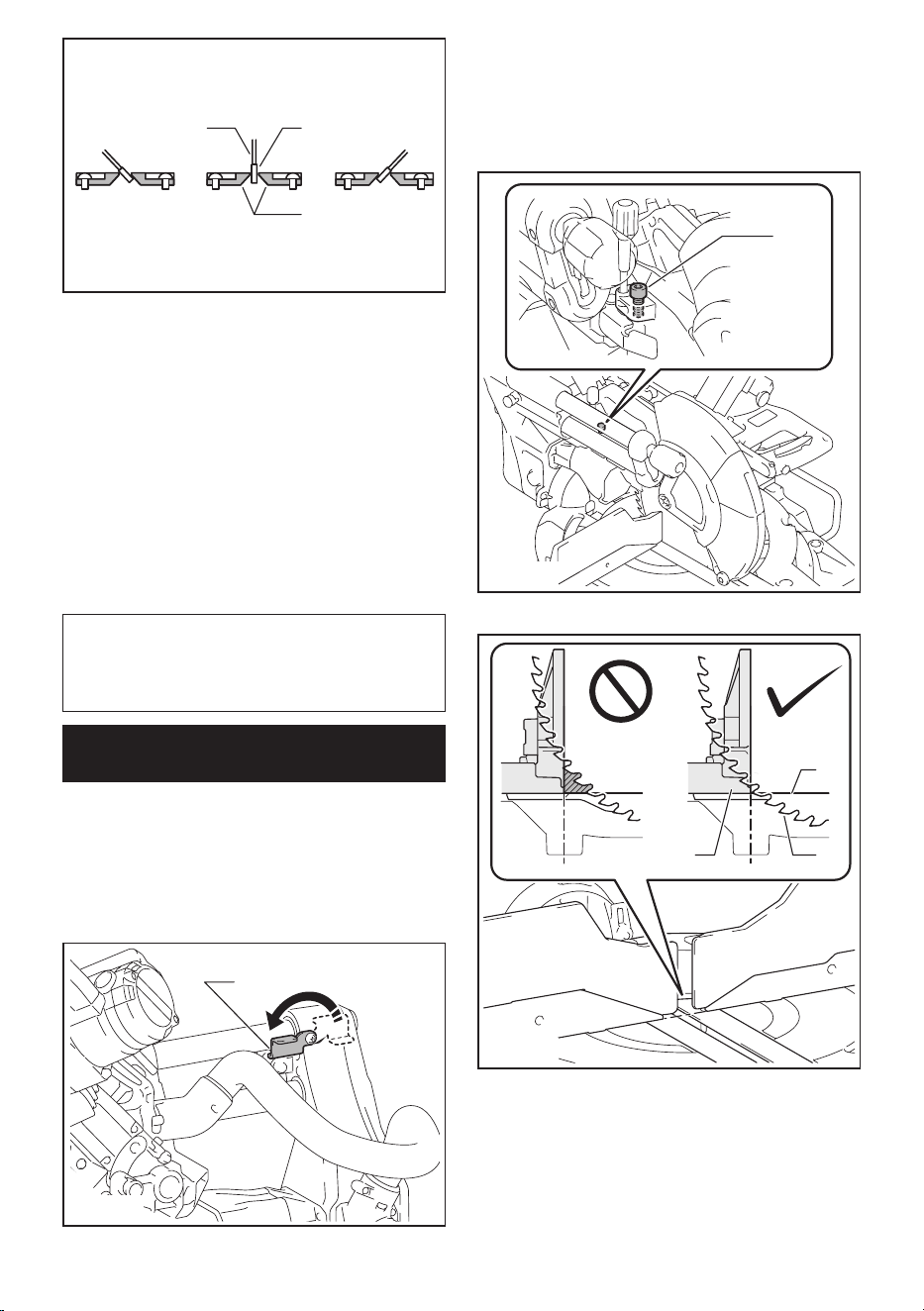
11 ENGLISH
1
23
4
6
5
► 1. Left bevel cut 2. Straight cut 3. Right bevel cut
4. Saw blade 5. Blade teeth 6. Kerf board
First, unplug the tool. Loosen all the screws (2 each on left
and right) securing the kerf boards until the kerf boards
can still be easily moved by hand. Lower the handle fully,
then pull and turn the stopper pin to lock the handle in the
lowered position. Release the stopper pin on the sliding pole
and pull the carriage toward you fully. Adjust the kerf boards
so that the kerf boards just contact the sides of the blade
teeth. Tighten the front screws (do not tighten rmly). Push
the carriage toward the guide fence fully and adjust the kerf
boards so that the kerf boards just contact the sides of blade
teeth. Tighten the rear screws (do not tighten rmly).
After adjusting the kerf boards, release the stopper
pin and raise the handle. Then tighten all the screws
securely.
NOTICE: After setting the bevel angle ensure
that the kerf boards are adjusted properly. Correct
adjustment of the kerf boards will help provide proper
support of the workpiece minimizing workpiece tear
out.
Maintaining maximum cutting
capacity
This tool is factory adjusted to provide the maximum
cutting capacity for 255 mm or 260 mm saw blade.
When installing a new blade, always check the lower
limit position of the blade and if necessary, adjust it as
follows:
First, unplug the tool. Turn the stopper lever to engaged
position.
1
► 1. Stopper lever
Push the carriage toward the guide fence fully and
lower the handle completely.
Adjust the blade position by turning the adjusting bolt
with the hex wrench. The periphery of the blade should
extend slightly below the top surface of the turn base
and also comes to the point where the front face of the
guide fence meets the top surface of the turn base.
1
► 1. Adjusting bolt
1
23
► 1. Top surface of turn base 2. Periphery of blade
3. Guide fence
With the tool unplugged, rotate the blade by hand while
holding the handle all the way down to be sure that
the blade does not contact any part of the lower base.
Re-adjust slightly, if necessary.
After adjustment, always return the stopper lever to the
original position.
12 ENGLISH
WARNING: After installing a new blade and
with the tool unplugged, always be sure that the
blade does not contact any part of the lower base
when the handle is lowered completely. If a blade
makes contact with the base it may cause kickback
and result in serious personal injury.
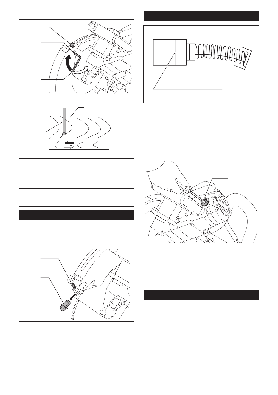
Stopper arm
The lower limit position of the blade can be easily
adjusted with the stopper arm. To adjust it, turn the
stopper arm in the direction of the arrow as shown in the
gure. Turn the adjusting screw so that the blade stops
at the desired position when lowering the handle fully.
1
2
► 1. Stopper arm 2. Adjusting screw
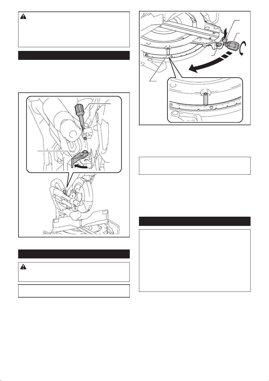
Adjusting the miter angle
CAUTION: After changing the miter angle,
always secure the turn base by tightening the grip
rmly.
NOTICE: When turning the turn base, be sure to
raise the handle fully.
1
2
3
4
► 1. Lock lever 2. Grip 3. Releasing lever 4. Pointer
Rotate the grip counterclockwise to unlock the turn
base. Turn the grip while holding down the lock lever to
move the turn base. Align the pointer with your desired
angle on the scale then tighten the grip.
NOTE: If you depress the releasing lever, you can
move the turn base without holding down the lock
lever. Tighten the grip at your desired position.
This miter saw employs positive stop function. You can
set 0°, 15°, 22.5°, 31.6°, 45°, and 60° right/left miter
angle quickly. To use this function, move the turn base
close to your desired positive stop angle while holding
down the lock lever. Then release the lock lever and
move the turn base to your desired positive stop angle
until the turn base is locked.
Adjusting the bevel angle
NOTICE: Always remove the upper guide fences
and vertical vise before adjusting the bevel angle.
NOTICE: When changing bevel angles, be sure
to position the kerf boards appropriately as
explained in the "Kerf boards" section.
NOTICE: When tilting the saw blade, be sure to
raise the handle fully.
NOTICE: Do not tighten the knob too hard. Doing
so may cause malfunction of the locking mecha-
nism of the bevel angle.
13 ENGLISH
1. Turn the knob on the slide pole counterclockwise.
1
► 1. Knob
2. Pull and turn the latch lever to the position as
illustrated.
1
► 1. Latch lever
3. Match the pointer with your desired angle on the
scale by moving the carriage then tighten the knob.
1
2
► 1. Bevel angle scale 2. Pointer
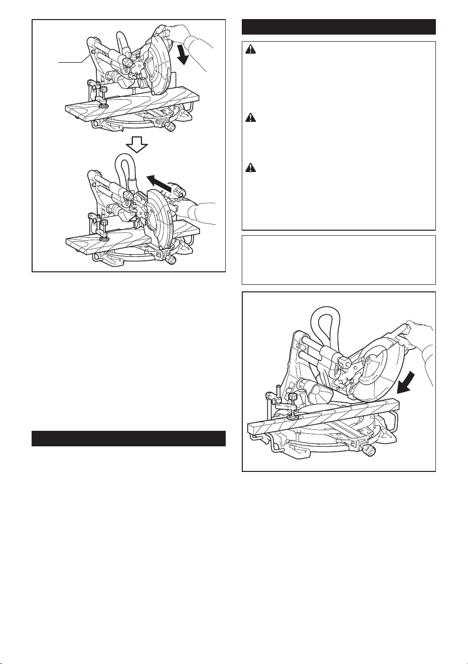
To tilt the carriage to the right, tilt the carriage to the left
slightly and then tilt it to the right while pressing down
the releasing button.
1
► 1. Releasing button
14 ENGLISH
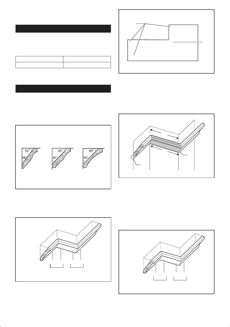
If you perform a bevel cut greater than 45°, move the
carriage while sliding the releasing lever toward the
front of the tool. You can perform up to 48° bevel cut.
1
► 1. Releasing lever
This miter saw employs positive stop function. You can set
22.5° and 33.9° angle to both right and left quickly. Set the
latch lever in the position as illustrated and tilt the carriage.
To change the angle, pull the latch lever and tilt the carriage.
1
► 1. Latch lever
CAUTION: After changing the bevel angle,
always secure the knob.
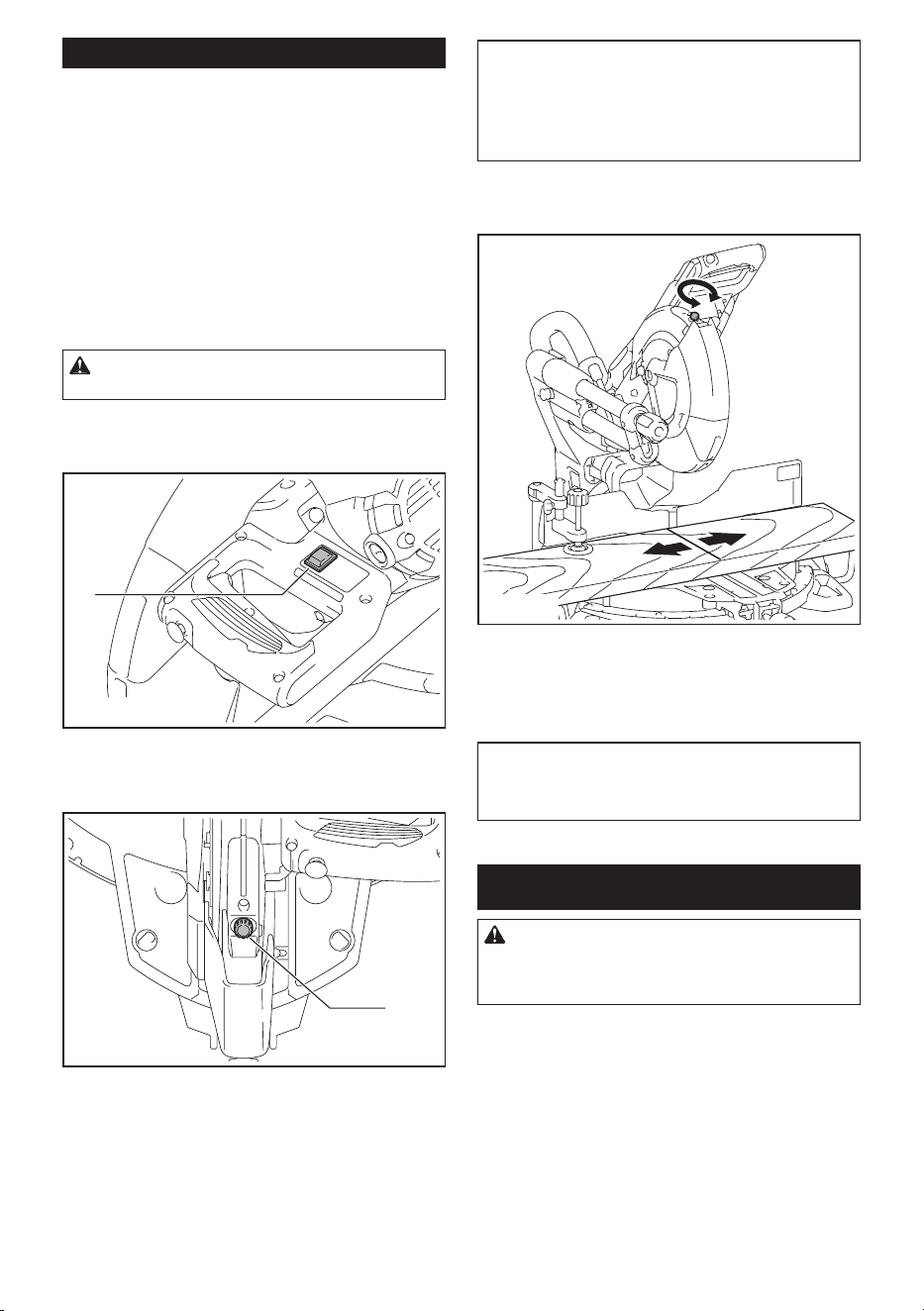
Slide lock
To lock the sliding movement of the carriage, push the carriage toward
the guide fence until it stops. Pull the stopper pin and rotate it 90°.
3
1
2
►
1. Unlocked position 2. Locked position 3. Stopper pin
Switch action
WARNING: Before plugging in the tool,
always check to see that the switch trigger actu-
ates properly and returns to the "OFF" position
when released. Do not pull the switch trigger hard
without pressing in the lock-off button. This can
cause switch breakage. Operating a tool with a
switch that does not actuate properly can lead to loss
of control and serious personal injury.
WARNING: NEVER use tool without a fully
operative switch trigger. Any tool with an inoper-
ative switch is HIGHLY DANGEROUS and must be
repaired before further usage or serious personal
injury may occur.
WARNING: NEVER defeat the lock-off button
by taping down or some other means. A switch with
a negated lock-off button may result in unintentional
operation and serious personal injury.
WARNING: NEVER use the tool if it runs when
you simply pull the switch trigger without press-
ing the lock-off button. A switch in need of repair
may result in unintentional operation and serious
personal injury. Return tool to a Makita service center
for proper repairs BEFORE further usage.
1
2
3
► 1. Switch trigger 2. Lock-off button 3. Hole for
padlock
To prevent the switch trigger from being accidentally
pulled, a lock-off button is provided. To start the tool,
press in the lock-off button and pull the switch trigger.
Release the switch trigger to stop.
A hole is provided in the switch trigger for insertion of a
padlock to lock the tool off.
WARNING: Do not use a lock with a shank or
cable any smaller than 6.35 mm (1/4") in diameter.
A smaller shank or cable may not properly lock the
tool in the off position and unintentional operation
may occur resulting in serious personal injury.
15 ENGLISH
Electronic function
Constant speed control
The tool is provided with an electronic speed control
which helps maintain a constant blade rotation speed
even under load. A constant blade rotation speed will
result in a very smooth cut.
Soft start feature
This function allows the smooth start-up of the tool by
limiting the start-up torque.
Laser beam action
For model LS1019L only
CAUTION: Never look into the laser beam.
Direct laser beam may injure your eyes.
To turn on the laser beam, press the upper position (I)
of the switch. To turn off the laser beam, press the lower
position (0) of the switch.
1
► 1. Switch for laser
Laser line can be shifted to either the left or right side of
the saw blade by turning the adjusting screw as follows.
1
► 1. Adjusting screw
1. Loosen the adjusting screw by turning it
counterclockwise.
2. With the adjusting screw loosened, slide the
adjusting screw to the right or left as far as it goes.
3. Tighten the adjusting screw rmly at the position
where it stops sliding.
NOTE: Laser line is factory adjusted so that it is posi-
tioned within 1 mm from the side surface of the blade
(cutting position).
NOTE: When laser line appears dim and hard to see
because of direct sunlight, relocate the work area to a
place where there is less direct sunlight.
Aligning the laser line
Align the cutting line on your workpiece with the laser
line.
A
B
A) When you want to obtain the correct size on the left
side of workpiece, shift the laser line to the left of the
blade.
B) When you want to obtain the correct size on the right
side of workpiece, shift the laser line to the right of the
blade.
NOTE: Use wood facing against the guide fence
when aligning the cutting line with the laser line at the
side of guide fence in compound cutting (bevel angle
45° and miter angle right 45°).
ASSEMBLY
WARNING: Always be sure that the tool is
switched off and unplugged before working on
the tool. Failure to switch off and unplug the tool may
result in serious personal injury.
16 ENGLISH
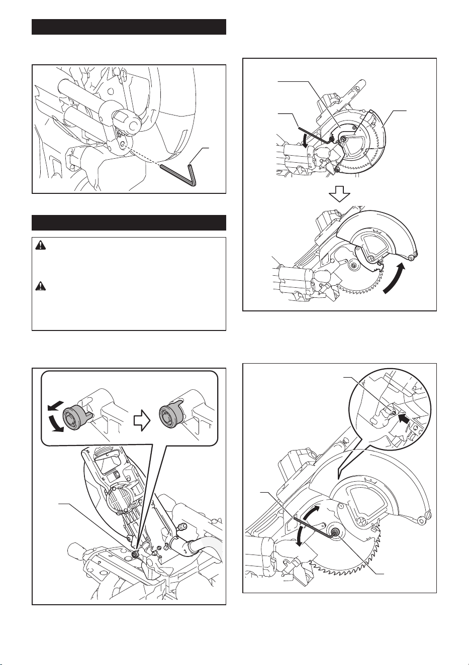
Hex wrench storage
When not in use, store the hex wrench as shown in the
gure to keep it from being lost.
1
► 1. Hex wrench
Removing and installing saw blade
WARNING: Always be sure that the tool is
switched off and unplugged before installing or
removing the blade. Accidental start up of the tool
may result in serious personal injury.
WARNING: Use only the Makita wrench pro-
vided to install or remove the blade. Failure to use
the wrench may result in overtightening or insufcient
tightening of the hex socket bolt and serious personal
injury.
Always lock the carriage with raised position when
removing and installing the blade. Pull the stopper pin
and rotate it 90° with the carriage raised.
12
3
► 1. Unlocked position 2. Locked position 3. Stopper
pin
Removing the blade
Loosen the hex bolt holding the center cover using the
hex wrench. Raise the blade guard and center cover.
3
1
2
► 1. Center cover 2. Hex wrench 3. Blade guard
Press the shaft lock to lock the spindle and use the hex
wrench to loosen the hex socket bolt. Then remove the
hex socket bolt, outer ange and blade.
1
2
4
5
3
► 1. Shaft lock 2. Hex wrench 3. Hex socket bolt (left-
handed) 4. Loosen 5. Tighten
17 ENGLISH
Installing the blade
Mount the blade carefully onto the spindle, making
sure that the direction of the arrow on the surface of the
blade matches the direction of the arrow on the blade
case.
1
2
► 1. Arrow on the blade case 2. Arrow on the blade
Install the outer ange and hex socket bolt. Tighten the
hex socket bolt counterclockwise using the hex wrench
while pressing the shaft lock.
1 2
345
6
► 1. Hex socket bolt 2. Outer ange 3. Saw blade
4. Inner ange 5. Spindle 6. Ring
NOTICE: If the inner ange is removed, be sure to
install it on the spindle with its protrusion facing away
from the blade. If the ange is installed incorrectly, the
ange will rub against the machine.
Return the blade guard and center cover to its original
position. Then tighten the hex bolt clockwise to secure
the center cover. Unlock the stopper pin to release
carriage from the raised position. Lower the handle to
make sure that the blade guard moves properly. Make
sure shaft lock has released spindle before making cut.
WARNING: Before mounting the blade onto
the spindle, always be sure that the correct ring
for the blade's arbor hole you intend to use is
installed between the inner and the outer anges.
Use of the incorrect arbor hole ring may result in the
improper mounting of the blade causing blade move-
ment and severe vibration resulting in possible loss
of control during operation and in serious personal
injury.
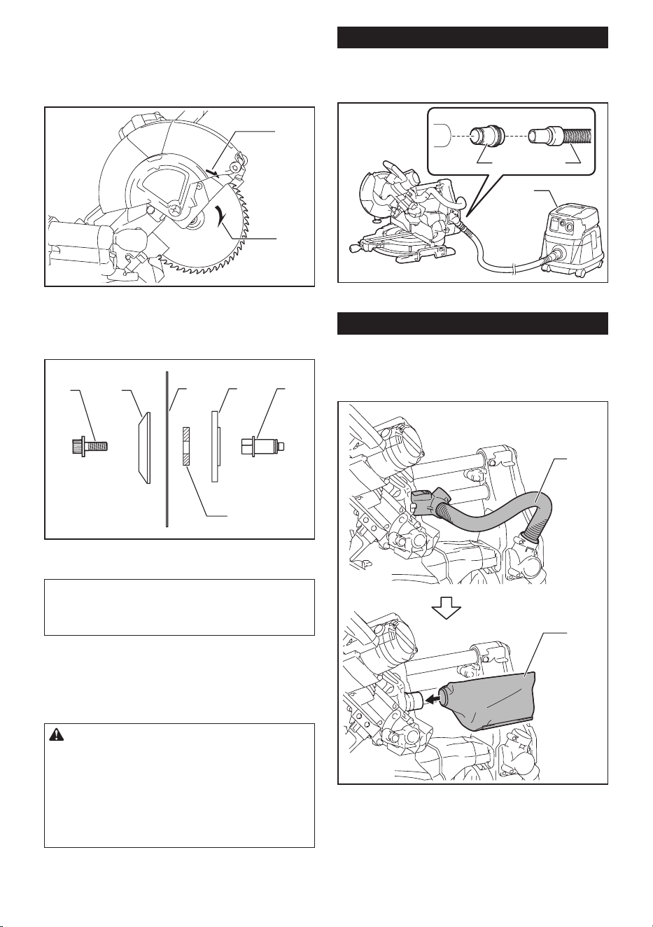
Connecting a vacuum cleaner
When you wish to perform clean cutting operation, con-
nect a Makita vacuum cleaner to the dust nozzle using
a front cuff 24 (optional accessory).
1 2
3
► 1. Front cuff 24 2. Hose 3. Vacuum cleaner
Dust bag
The use of the dust bag makes cutting operations clean
and dust collection easy. To attach the dust bag, remove
the dust extraction hose from the tool and connect the
dust bag.
1
2
► 1. Dust extraction hose 2. Dust bag
18 ENGLISH
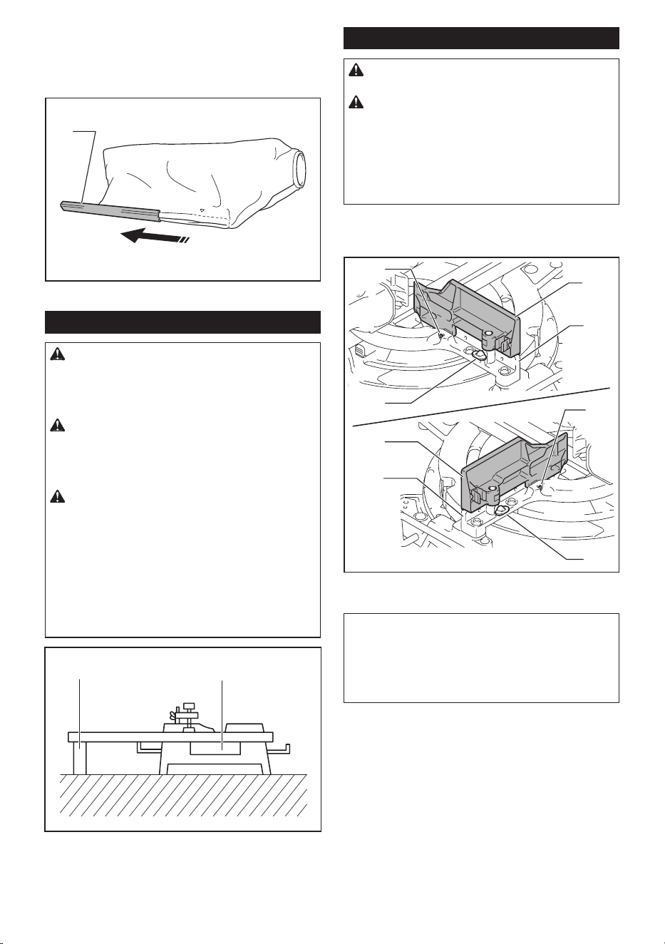
When the dust bag is about half full, remove the dust
bag from the tool and pull the fastener out. Empty
the dust bag of its contents, tapping it lightly so as to
remove particles adhering to the insides which might
hamper further collection.
1
► 1. Fastener
Securing workpiece
WARNING: It is extremely important to always
secure the workpiece correctly with the proper
type of vise or crown molding stoppers. Failure to
do so may result in serious personal injury and cause
damage to the tool and/or the workpiece.
WARNING: After a cutting operation, do
not raise the saw blade until it has come to a
complete stop. The raising of a coasting blade may
result in serious personal injury and damage to the
workpiece.
WARNING: When cutting a workpiece that
is longer than the support base of the saw, the
material should be supported the entire length
beyond the support base and at the same height
to keep the material level. Proper workpiece support
will help avoid blade pinch and possible kickback
which may result in serious personal injury. Do not
rely solely on the vertical vise and/or horizontal vise
to secure the workpiece. Thin material tends to sag.
Support workpiece over its entire length to avoid
blade pinch and possible KICKBACK.
1
2
► 1. Support 2. Turn base
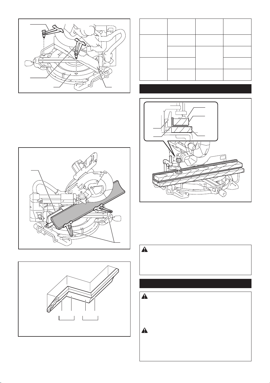
Guide fences
WARNING: Before operating the tool, make
sure that the upper fence is secured rmly.
WARNING: Before bevel-cutting, make sure
that no part of the tool, especially the blade, con-
tacts the upper and lower fences when fully low-
ering and raising the handle in any position and
while moving the carriage through its full range
of travel. If the tool or blade makes contact with
the fence this may result in kickback or unexpected
movement of the material and serious personal injury.
Use upper fences to support the material higher than
the lower fences. Insert the upper fence into the hole on
the lower fence and tighten the clamping screw.
1
2
3
1
2
3
4
4
► 1. Upper fence 2. Lower fence 3. Clamping screw
4. Adjusting screw
NOTICE: The lower fences are xed to the base in
the factory. Do not remove the lower fences.
NOTICE: If the upper fence is still loose after tight-
ening the clamping screw, turn the adjusting screw to
close a gap. The adjusting screw is factory adjusted.
You don't need to use it unless needed.
19 ENGLISH
You can store the upper fences onto the holder when not in
use. Use the clip on the upper fence to hold it on the holder.
1 2
3
► 1. Holder 2. Upper fence 3. Clip
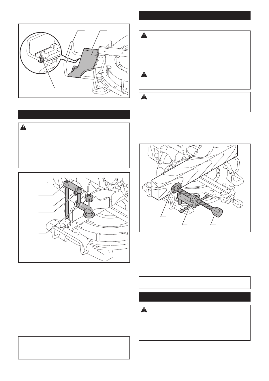
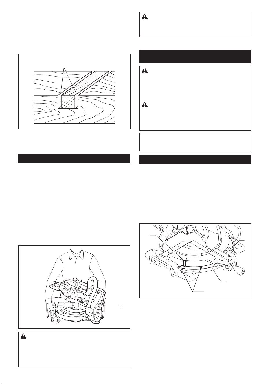
Vertical vise
WARNING: The workpiece must be secured
rmly against the turn base and guide fence with
the vise during all operations. If the workpiece is
not properly secured against the fence the material
may move during the cutting operation causing
possible damage to the blade, causing the material
to be thrown and loss of control resulting in serious
personal injury.
1
2
3
4
►
1. Vise arm 2. Vise rod 3. Clamping screw 4. Vise knob
The vertical vise can be installed in two positions on
either the left or right side of the base. Insert the vise
rod into the hole in the base.
Position the vise arm according to the thickness and shape
of the workpiece and secure the vise arm by tightening the
screw. If the clamping screw contacts the carriage, install it
on the opposite side of vise arm. Make sure that no part of
the tool contacts the vise when lowering the handle all the
way. If some part contacts the vise, re-position the vise.
Press the workpiece at against the guide fence and the
turn base. Position the workpiece at the desired cutting
position and secure it rmly by tightening the vise knob.
NOTE: For a quick setting of workpiece, turning the
vise knob to 90° counterclockwise allows the vise
knob to be moved up and down. To secure the work-
piece after setting, turn the vise knob clockwise.
Horizontal vise
Optional accessory
WARNING: Always rotate the vise nut clock-
wise until the workpiece is properly secured. If the
workpiece is not properly, secured the material may
move during the cutting operation causing possible
damage to the saw blade, causing the material to be
thrown and loss of control resulting in serious per-
sonal injury.
WARNING: When cutting a thin workpiece,
such as base boards, against the fence, always
use the horizontal vise.
CAUTION: When cutting the workpiece of the
thickness 20 mm or thinner, make sure to use a
spacer block to secure the workpiece.
The horizontal vise can be installed in two positions on
either the left or right side of the base. When performing
22.5° or greater miter cuts, install the horizontal vise on
the side opposite the direction in which the turn base is
to be turned.
1
2 3
► 1. Vise plate 2. Vise nut 3. Vise knob
By ipping the vise nut counterclockwise, the vise is
released, and rapidly moves in and out. To grip the
workpiece, push the vise knob forward until the vise
plate contacts the workpiece and ip the vise nut clock-
wise. Then turn the vise knob clockwise to secure the
workpiece.
NOTE: The maximum width of workpiece which can
be secured by the horizontal vise is 228 mm.
Holders
WARNING: Always support a long workpiece
so it is level with the top surface of the turn base
for an accurate cut and to prevent dangerous loss
of tool control. Proper workpiece support will help
avoid blade pinch and possible kickback which may
result in serious personal injury.
20 ENGLISH
To hold long workpieces horizontally, holders are pro-
vided on both sides of the tool. Loosen the screws and
extend the holders to the appropriate length for holding
the workpiece. Then tighten the screws.
1
2
► 1. Holder 2. Screw
OPERATION
WARNING: Make sure the saw blade is not
contacting the workpiece, etc. before the switch
is turned on. Turning the tool on with the blade in
contact with the workpiece may result in kickback and
serious personal injury.
WARNING: After a cutting operation, do
not raise the saw blade until it has come to a
complete stop. The raising of a coasting blade may
result in serious personal injury and damage to the
workpiece.
WARNING: Do not perform any adjustment
such as turning grip, knob, and levers on the tool
while the saw blade is rotating. Adjustment while
the blade is rotating may result in serious personal
injury.
NOTICE: Before use, be sure to unlock the stop-
per pin and release the handle from the lowered
position.
NOTICE: Do not apply excessive pressure on the
handle when cutting. Too much force may result in
overload of the motor and/or decreased cutting ef-
ciency. Press down handle with only as much force as
necessary for smooth cutting and without signicant
decrease in blade speed.
NOTICE: Gently press down the handle to per-
form the cut. If the handle is pressed down with force
or if lateral force is applied, the blade may vibrate and
leave a mark (saw mark) in the workpiece and the
precision of the cut may be impaired.
NOTICE: During a slide cut, gently push the
carriage toward the guide fence without stopping.
If the carriage movement is stopped during the cut, a
mark will be left in the workpiece and the precision of
the cut will be impaired.
Press cutting
WARNING: Always lock the sliding movement
of the carriage when performing a press cutting.
Cutting without lock may cause possible kickback
which may result in serious personal injury.
Workpieces up to 68 mm high and 160 mm wide can be
cut in the following manner.
1
► 1. Stopper pin
1. Push the carriage toward the guide fence until it
stops and lock it with the stopper pin.
2. Secure the workpiece with the proper type of vise.
3. Switch on the tool without the blade making any
contact and wait until the blade attains full speed before
lowering.
4. Gently lower the handle to the fully lowered posi-
tion to cut the workpiece.
5. When the cut is completed, switch off the tool and
wait until the saw blade has come to a complete
stop before returning the blade to its fully elevated
position.
Slide (push) cutting (cutting wide
workpieces)
WARNING: Whenever performing a slide cut,
rst pull the carriage full towards you and press
the handle all the way down, then push the car-
riage toward the guide fence. Never start the cut
with the carriage not pulled fully toward you. If
you perform the slide cut without the carriage pulled
fully toward you, unexpected kickback may occur and
serious personal injury may result.
WARNING: Never attempt to perform a slide
cut by pulling the carriage towards you. Pulling
the carriage towards you while cutting may cause
unexpected kickback resulting in possible serious
personal injury.
WARNING: Never perform the slide cut with
the handle locked in the lowered position.
21 ENGLISH
1
► 1. Stopper pin
1. Unlock the stopper pin so that the carriage can
slide freely.
2. Secure the workpiece with the proper type of vise.
3. Pull the carriage toward you fully.
4. Switch on the tool without the saw blade making
any contact and wait until the saw blade attains full
speed.
5. Press the handle down and push the carriage
toward the guide fence and through the workpiece.
6. When the cut is completed, switch off the tool and
wait until the saw blade has come to a complete
stop before returning the blade to its fully elevated
position.
Miter cutting
Refer to the section for adjusting the miter angle.
Bevel cut
WARNING: After setting the blade for a bevel
cut, ensure that the carriage and saw blade will
have free travel throughout the entire range of the
intended cut before operating the tool. Interruption
of the carriage or blade travel during the cutting oper-
ation may result in kickback and serious personal
injury.
WARNING: While making a bevel cut, keep
hands out of the path of the saw blade. The angle
of the blade may confuse the operator as to the actual
blade path while cutting and contact with the blade
will result in serious personal injury.
WARNING: The saw blade should not be
raised until it has come to a complete stop. During
a bevel cut, the piece cut off may come to rest against
the saw blade. If the blade is raised while it is rotating,
the cut-off piece may be ejected by the blade causing
the material to fragment which may result in serious
personal injury.
NOTICE: When pressing down the handle, apply
pressure in parallel with the blade. If a force is
applied perpendicularly to the turn base or if the pres-
sure direction is changed during a cut, the precision
of the cut will be impaired.
1. Remove the upper fence on the side that you are
going to tilt the carriage.
2. Unlock the stopper pin.
3. Adjust the bevel angle according to the procedure
explained in the section for bevel angle adjustment.
Then tighten the knob.
4. Secure the workpiece with a vise.
5. Pull the carriage toward you fully.
6. Switch on the tool without the blade making any
contact and wait until the blade attains full speed.
7. Gently lower the handle to the fully lowered posi-
tion while applying pressure in parallel with the blade
and push the carriage toward the guide fence to cut
the workpiece.
22 ENGLISH
8. When the cut is completed, switch off the tool and
wait until the blade has come to a complete stop
before returning the blade to its fully elevated position.
Compound cutting
Compound cutting is the process in which a bevel
angle is made at the same time in which a miter angle
is being cut on a workpiece. Compound cutting can be
performed at the angle shown in the table.
Miter angle Bevel angle
Left and Right 0° - 45° Left and Right 0° - 45°
When performing compound cutting, refer to the section
for press cutting, slide (push) cutting, miter cutting and
bevel cut.
Cutting crown and cove moldings
Crown and cove moldings can be cut on a compound
miter saw with the moldings laid at on the turn base.
There are two common types of crown moldings and
one type of cove moldings; 52/38° wall angle crown
molding, 45° wall angle crown molding and 45° wall
angle cove molding.
123
► 1. 52/38° type crown molding 2. 45° type crown
molding 3. 45° type cove molding
There are crown and cove molding joints which are
made to t "Inside" 90° corners ((a) and (b) in the gure)
and "Outside" 90° corners ((c) and (d) in the gure.)
(a) (b) (c) (d)
12
1. Inside corner 2. Outside corner
2
(a)
(b)
(a)
(b)
(b)
(a)
(b)
(a)
(a)
(b)
(c)
(d)
1
1. Inside corner 2. Outside corner
Measuring
Measure the wall width, and adjust the width of the
workpiece according to it. Always make sure that width
of the workpiece's wall contact edge is the same as wall
length.
2
3
1
4
► 1. Workpiece 2. Wall width 3. Width of the work-
piece 4. Wall contact edge
Always use several pieces for test cuts to check the
saw angles.
When cutting crown and cove moldings, set the bevel
angle and miter angle as indicated in the table (A) and
position the moldings on the top surface of the saw
base as indicated in the table (B).
In the case of left bevel cut
(a) (b) (c) (d)
12
1. Inside corner 2. Outside corner
23 ENGLISH
Table (A)
– Molding
position
in the
gure
Bevel angle Miter angle
52/38°
type
45° type 52/38°
type
45° type
For
inside
corner
(a) Left
33.9°
Left 30° Right
31.6°
Right
35.3°
(b) Left
31.6°
Left
35.3°
For
outside
corner
(c)
(d) Right
31.6°
Right
35.3°
Table (B)
– Molding
position in
the gure
Molding
edge against
guide fence
Finished
piece
For inside
corner
(a) Ceiling
contact edge
should be
against guide
fence.
Finished
piece will be
on the Left
side of blade.
(b) Wall contact
edge should
be against
guide fence.
For outside
corner
(c) Finished
piece will be
on the Right
side of blade.(d) Ceiling
contact edge
should be
against guide
fence.
Example:
In the case of cutting 52/38° type crown molding for
position (a) in the above gure:
• Tilt and secure bevel angle setting to 33.9° LEFT.
• Adjust and secure miter angle setting to 31.6°
RIGHT.
• Lay crown molding with its broad back (hidden)
surface down on the turn base with its CEILING
CONTACT EDGE against the guide fence on the
saw.
• The nished piece to be used will always be on
the LEFT side of the blade after the cut has been
made.
In the case of right bevel cut
(a) (b) (c) (d)
12
1. Inside corner 2. Outside corner
Table (A)
– Molding
position
in the
gure
Bevel angle Miter angle
52/38°
type
45° type 52/38°
type
45° type
For
inside
corner
(a) Right
33.9°
Right
30°
Right
31.6°
Right
35.3°
(b) Left
31.6°
Left
35.3°
For
outside
corner
(c)
(d) Right
31.6°
Right
35.3°
Table (B)
– Molding
position in
the gure
Molding
edge against
guide fence
Finished
piece
For inside
corner
(a) Wall contact
edge should
be against
guide fence.
Finished
piece will be
on the Right
side of blade.
(b) Ceiling
contact edge
should be
against guide
fence.
For outside
corner
(c) Finished
piece will be
on the Left
side of blade.
(d) Wall contact
edge should
be against
guide fence.
Example:
In the case of cutting 52/38° type crown molding for
position (a) in the above gure:
• Tilt and secure bevel angle setting to 33.9° RIGHT.
•
Adjust and secure miter angle setting to 31.6° RIGHT.
•
Lay crown molding with its broad back (hidden) sur-
face down on the turn base with its WALL CONTACT
EDGE against the guide fence on the saw.
• The nished piece to be used will always be on
the RIGHT side of the blade after the cut has been
made.
Crown molding stopper
Optional accessory
Crown molding stoppers allow easier cuts of crown
molding without tilting the saw blade. Install them on the
turn base as shown in the gures.
At right 45° miter angle
1
2
3
4
► 1. Crown molding stopper L 2. Crown molding stop-
per R 3. Turn base 4. Guide fence
24 ENGLISH
At left 45° miter angle
1
2
34
► 1. Crown molding stopper L 2. Crown molding stop-
per R 3. Turn base 4. Guide fence
Position crown molding with its WALL CONTACT EDGE
against the guide fence and its CEILING CONTACT
EDGE against the crown molding stoppers as shown in
the gure. Adjust the crown molding stoppers according
to the size of the crown molding. Tighten the screws to
secure the crown molding stoppers. Refer to the table
(C) for the miter angle.
1
2
► 1. Guide fence 2. Crown molding stopper
(a) (b) (c) (d)
12
1. Inside corner 2. Outside corner
Table (C)
– Molding
position in
the gure
Miter angle Finished
piece
For inside
corner
(a) Right 45° Save the right
side of blade
(b) Left 45° Save the left
side of blade
For outside
corner
(c) Save the right
side of blade
(d) Right 45° Save the left
side of blade
Cutting aluminum extrusion
1
5
3
4
2
► 1. Vise 2. Spacer block 3. Guide fence 4. Aluminum
extrusion 5. Spacer block
When securing aluminum extrusions, use spacer blocks
or pieces of scrap as shown in the gure to prevent
deformation of the aluminum. Use a cutting lubricant
when cutting the aluminum extrusion to prevent build-up
of the aluminum material on the blade.
WARNING: Never attempt to cut thick or
round aluminum extrusions. Thick or round alumi-
num extrusions can be difcult to secure and the work
may loosen during the cutting operation which may
result in loss of control and serious personal injury.
Groove cutting
WARNING: Do not attempt to perform this
type of cut by using a wider type blade or dado
blade. Attempting to make a groove cut with a wider
blade or dado blade could lead to unexpected cutting
results and kickback which may result in serious
personal injury.
WARNING: Be sure to return the stopper arm
to the original position when performing other
than groove cutting. Attempting to make cuts with
the stopper arm in the incorrect position could lead to
unexpected cutting results and kickback which may
result in serious personal injury.
25 ENGLISH
For a dado type cut, perform as follows:
1.
Adjust the lower limit position of the saw blade using
the adjusting screw and the stopper arm to limit the cutting
depth of the saw blade. Refer to the section for stopper arm.
2. After adjusting the lower limit position of the saw
blade, cut parallel grooves across the width of the work-
piece using a slide (push) cut.
1
► 1. Cut grooves with blade
3. Remove the workpiece material between the
grooves with a chisel.
Carrying tool
Before carrying, make sure to unplug and all movable parts
of the miter saw are secured. Always check the following:
• The tool is unplugged.
• The carriage is at 0° bevel angle position and
secured.
• The carriage is lowered and locked.
• The carriage is fully slid to the guide fence and
locked.
• The turn base is at the full right miter angle posi-
tion and secured.
• The holders are stored and secured.
Carry the tool by holding both sides of the tool base as
shown in the gure.
WARNING: Stopper pin for carriage elevation
is for carrying and storage purposes only and not
for any cutting operations. The use of the stopper
pin for cutting operations may cause unexpected
movement of the saw blade resulting in kickback and
serious personal injury.
CAUTION: Always secure all moving portions
before carrying the tool. If portions of the tool move
or slide while being carried, loss of control or balance
may occur and result in personal injury.
MAINTENANCE
WARNING: Always be sure that the tool is
switched off and unplugged before attempting
to perform inspection or maintenance. Failure to
unplug and switch off the tool may result in accidental
start up of the tool which may result in serious per-
sonal injury.
WARNING: Always be sure that the blade is
sharp and clean for the best and safest perfor-
mance. Attempting a cut with a dull and /or dirty blade
may cause kickback and result in a serious personal
injury.
NOTICE: Never use gasoline, benzine, thinner,
alcohol or the like. Discoloration, deformation or
cracks may result.
Adjusting the cutting angle
This tool is carefully adjusted and aligned at the factory,
but rough handling may have affected the alignment. If
your tool is not aligned properly, perform the following:
Miter angle
Lower the handle fully and lock it in the lowered position
by the stopper pin. Push the carriage toward the guide
fence. Loosen the grip and the screws which secure the
pointer and miter angle scale.
2
1
2
3
► 1. Screw on pointer 2. Screws on miter angle scale
3. Miter scale
26 ENGLISH
Set the turn base to the 0° position using the positive
stop function. Square the side of the blade with the face
of the guide fence using a triangular rule or try-square.
While keeping the square, tighten the screws on the
miter angle scale. After that, align the pointers (both
right and left) with the 0° position in the miter angle
scale and then tighten the screw on the pointer.
1
► 1. Triangular rule
Bevel angle
0° bevel angle
Push the carriage toward the guide fence and lock the
sliding movement by the stopper pin. Lower the handle
fully and lock it in the lowered position by the stopper
pin and then loosen the knob. Turn the 0° adjusting bolt
two or three revolutions counterclockwise to tilt the saw
blade to the right.
1
2
► 1. 0° Adjusting bolt 2. Screw
Carefully square the side of the saw blade with the top
surface of the turn base using the triangular rule, try-
square, etc. by turning the 0° adjusting bolt clockwise.
Then tighten the knob rmly to secure the 0° angle you
have set.
1
2
3
► 1. Triangular rule 2. Saw blade 3. Top surface of
turn base
Check if the side of the saw blade squares with the
turn base surface once again. Loosen the screw on the
pointer. Align the pointer with 0° position in the bevel
angle scale and then tighten the screw.
45° bevel angle
NOTICE: Before adjusting the 45° bevel angle,
nish 0° bevel angle adjustment.
Loosen the knob and fully tilt the carriage to the side
that you want to check. Check if the pointer indicates
the 45° position in the bevel angle scale.
27 ENGLISH
If the pointer does not indicate the 45° position, align
it with 45° position by turning the adjusting bolt on the
opposite side of the bevel angle scale.
1
2
► 1. Left 45° adjusting bolt 2. Right 45° adjusting bolt
Adjusting the laser line position
For model LS1019L only
WARNING: The tool must be plugged in while
adjusting the laser line. Take extra care not to
switch on the tool during adjustment. Accidental
start up of the tool may result in serious personal
injury.
CAUTION: Never look directly into the laser
beam. Direct eye exposure to the beam could cause
serious damage to your eyes.
NOTICE: Check the position of laser line regu-
larly for accuracy.
NOTICE: Beware that impacts to the tool. It may
cause the laser line to be misaligned or may cause
damage to the laser, shortening its life.
NOTICE: Have the tool repaired by a Makita
authorized service center for any failure on the
laser unit.
The movable range of laser line is decided by the range
adjustment screws on both sides. Perform following
procedures to alter the laser line position.
1. Unplug the tool.
2. Draw a cutting line on the workpiece and place it
on the turn base. At this time, do not secure the work-
piece with a vise or similar securing device.
3. Lower the handle and align the cutting line with
the saw blade.
4. Return the handle to the original position and
secure the workpiece with the vertical vise so that the
workpiece does not move from the position you have
determined.
5. Plug in the tool and turn on the laser switch.
6. Loosen the adjusting screw. To move the laser line
away from the blade, turn the range adjustment screws
counterclockwise. To move the laser line close to the
blade, turn the range adjustment screw clockwise.
Adjusting the laser line on the left side of the blade
1
2
3
4
5
► 1. Adjusting screw 2. Range adjustment screw
3. Hex wrench 4. Laser line 5. Saw blade
28 ENGLISH
Adjusting the laser line on the right side of the blade
1
2
3
4
5
► 1. Adjusting screw 2. Range adjustment screw
3. Hex wrench 4. Laser line 5. Saw blade
7. Slide the adjusting screw to the position that the
laser line comes onto the cutting line and then tighten.
NOTE: The movable range of laser line is factory
adjusted within 1 mm (0.04") from the side surface
of blade.
Cleaning the laser light lens
For model LS1019L only
The laser light becomes hard to see as the lens for the laser
light gets dirty. Clean the lens for laser light periodically.
1
2
► 1. Screw 2. Lens
Unplug the tool. Loosen the screw and pull out the lens.
Clean the lens gently with a damp soft cloth.
NOTICE: Do not remove the screw which
secures the lens. If the lens does not come out,
loosen the screw further.
NOTICE: Do not use solvents or any petro-
leum-based cleaners on the lens.
Replacing carbon brushes
1
► 1. Limit mark
Remove and check the carbon brushes regularly.
Replace when they wear down to the limit mark. Keep
the carbon brushes clean and free to slip in the holders.
Both carbon brushes should be replaced at the same
time. Use only identical carbon brushes.
Use a screwdriver to remove the brush holder caps.
Take out the worn carbon brushes, insert the new ones
and secure the brush holder caps.
1
► 1. Brush holder cap
After replacing brushes, plug in the tool and break in
brushes by running tool with no load for about 10 min-
utes. Then check the tool while running and electric
brake operation when releasing the switch trigger. If
the electric brake is not working correctly, have the tool
repaired by a Makita service center.
After use
After use, wipe off chips and dust adhering to the tool
with a cloth or the like. Keep the blade guard clean
according to the directions in the previously covered
section titled "Blade guard". Lubricate the sliding por-
tions with machine oil to prevent rust.
To maintain product SAFETY and RELIABILITY,
repairs, any other maintenance or adjustment should
be performed by Makita Authorized or Factory Service
Centers, always using Makita replacement parts.

29 ENGLISH
OPTIONAL
ACCESSORIES
WARNING: These Makita accessories or
attachments are recommended for use with your
Makita tool specied in this manual. The use of
any other accessories or attachments may result in
serious personal injury.
WARNING: Only use the Makita accessory
or attachment for its stated purpose. Misuse of
an accessory or attachment may result in serious
personal injury.
If you need any assistance for more details regard-
ing these accessories, ask your local Makita Service
Center.
• Steel & Carbide-tipped saw blades
• Vertical vise
• Horizontal vise
• Crown molding stopper set
• Dust bag
• Triangular rule
• Hex wrench
• Hex wrench (for LS1019L)
NOTE: Some items in the list may be included in the
tool package as standard accessories. They may
differ from country to country.

30

31

www.makita.com
Makita Europe N.V.
Makita Corporation
3-11-8, Sumiyoshi-cho,
Anjo, Aichi 446-8502 Japa
n
Jan-Baptist Vinkstraat 2,
3070 Kortenberg, Belgium
885575B224
EN
20190312