Loading ...
Loading ...
Loading ...
PART 1: HOOD INSTALLATION GUIDE
Integrated Hood with Integrated Fan Motor
Models included: X3M06S6.OU(T/B), X3M06S5.OP(T/B), X3UM06S5.OP(T/B), X3M09S6.OU(T/B), X3M09S5.OP(T/B), X3UM09S5.OP(T/B),
X3MD09S6.OU(T/B), X3MD09S5.OP(T/B), X3UD09S5.OP(T/B), X3MD12S6.OU(T/B), X3MD12S5.OP(T/B) and X3UD12S5.OP(T/B)
6
STEP 1:
To install into your overhead cupboard;
Top Ducting - several holes may need to be cut into shelves to enable the
ducting to exit the cabinetry.
Back Ducting - cut a rectangular or round hole through the wall taking into
account the rear duct outlet of the hood.
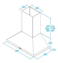
NOTE:
The height of the underside of the hood body must be a minimum of
600mm above an electric cooktop, for a gas cooktop a minimum of
600mm above the highest part of the highest burner and a maximum
height of 1200mm. If the instructions of the hob specify a greater distance than
the minimum detailed, this shall be the minimum height for installation.
A comfortable installation height would be 700 – 750mm gap between the
base of the rangehood and the highest part on your cooktop.
Building codes that stipulate a minimum dimension may vary from state to state,
please check with your local council prior to installation.
Ensure the hood is mounted as close to the centre of the cooking surface as
possible.
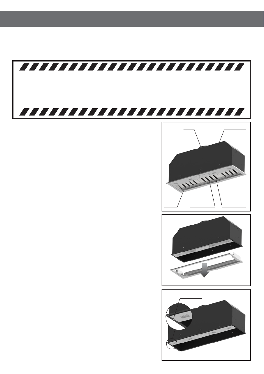
STEP 2:
Remove the three (3) screw xings from within the Main Chassis of the
rangehood located along the rear chassis wall (located above the grease trap),
along with two (2) screws on the left side and two (2) screws on the right side.
Once the screws are removed, the Fascia will separate away from the Main
Chassis.
STEP 3:
Fixing Holes are located on the returns of the main chassis. These Fixing Holes
are used to secure the main chassis to the cabinetry.
STEP 4:
Place the
Main Chassis in the cabinet ensuring that the hood is level and the
controls and display will be visible when standing in front of the unit.
WARNING
DIMENSIONS ARE ACCURATE AT THE TIME OF PRINTING, HAUS GROUP RESERVES THE RIGHT TO
CHANGE SPECIFICATIONS WITHOUT NOTICE. FOR BUILDING PURPOSES THE UNIT SHOULD BE
PROVIDED TO THE CABINET MAKER / BUILDER / KITCHEN DESIGNER FOR EXACT MEASUREMENTS.
Outlet
Bafe Filters Grease Trap
Main Chassis
Fascia
Step 2: Remove Fascia from Chassis
Fixing Holes
Step 3: Locate the Fixing Holes of the Main Chassis
Loading ...
Loading ...
Loading ...