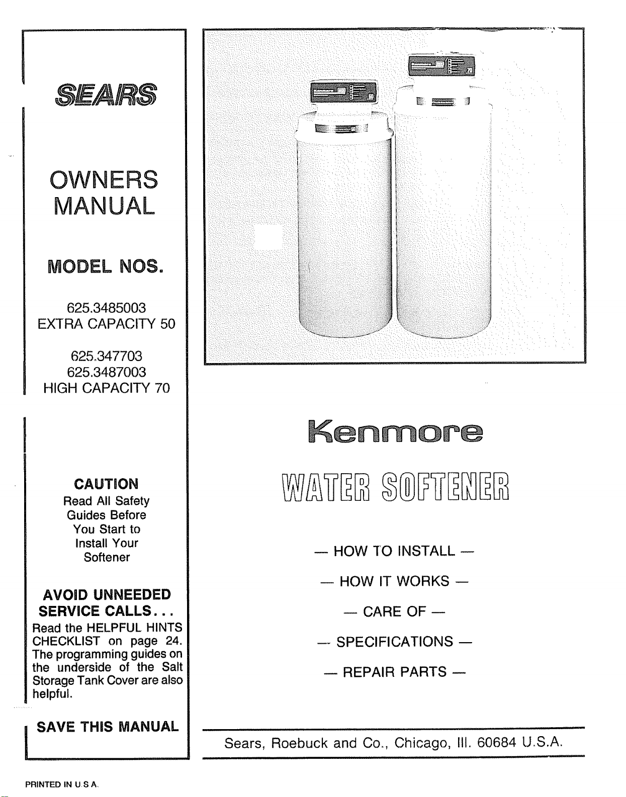
OWNERS
ANUAL
MODEL NOS.
625.3485003
EXTRA CAPACITY 50
62&347703
625.3487003
HIGH CAPACITY 70
CAUTION
Read All Safety
Guides Before
You Start to
Install Your
Softener
AVOID UNNEEDED
SERVICE CALLS...
Read the HELPFUL HINTS
CHECKLIST on page 24.
The programming guides on
the underside of the Salt
Storage Tank Cover are also
helpful.
SAVE THiS MANUAL
HOW TO INSTALL
HOW IT WORKS --
CARE OF
SPECIFICATIONS-
-- REPAIR PARTS --
Sears, Roebuck and Co., Chicago,
i i i/llJlun ,, i ,,utl/lll, t,,,
II1° 60684 U,S.A.
PRINTED tN US A.,
i,i ,,,,, ,ll ....... i,i ................................ ii, rl
t WARRANTY
I
FULL ONE YEAR WARRANTY ON WATER SOFTENER
For one year from the date of purchase, when this water softener is installed and maintained
in accordance with our' instructions, Sears will repair, free of charge, defects in material
or' workmanship in this water softener..
FULL TEN YEAR WARRANTY AGAINST LEAKS
For ten years from the date of purchase, Sears will furnish and install a new current model
water softener tank or salt storage drum, free of charge, if either the tank or drum develop
a leak.
TO OBTAIN WARRANT',( SERVICE, SIMPLY CONTACT THE NEAREST SEARS SERVICE
CENTER THROUGHOUT THE UNITED STATES. This warranty applies only while this pro-
duct is in use in the United States.
This warranty gives you specific legal rights, and you may have other rights which vary from
state to state_
Sears, Roebuck and Co.., Dept. 731-CR-W, Sears Tower', Chicago, IL 60684
If you want your water softener professionally installed, talk to your Sears Salesman. He will arrange for
a prompt, quality installation by Sears Authorized installers°
SEARS INSTALLATION POLICY
All installation labor arranged by Sears shall be per-
formed in a neat, workmanlike manner' in accordance
with generally accepted trade practices_ Further, alt
installations shall comply with all local laws, codes,
regulations and ordinances_ Customer shall also be
protected, during installation, by insurance relating
to Property Damage, Workman's Compensation and
Public Liability.
SEARS INSTALLATION WARRANTY
In addition to any warranty extended to you on the
Sears merchandise involved, which warranty
becomes effective the date the merchandise is in-
stalled, should the workmanship of any Sears
arranged installation prove faulty within one year,
Sears will, upon notice from you, cause such faults
to be corrected at no additional cost to you.
2

,,[,J_Ul_J,[i,,J_u,,,,ii,,,i,,,lllll,IIII'IIIH'II r',,' ' '
TABLE OF CONTENTS
SECTION 1
Unpacking The Softener ..................................................
Safety Guides .....................................................
PAGE
NO.
4
4
Before You Start To Install Your Softener ............................. 5-9
Water System Tests ............................................... 5
Where To Install The Softener .................................... 6
Plan How You Wilt Install The Softener ............................. 6-9
Tools, Pipe, Fittings and Other Materials Needed .................. 7-9
SECTION 3
Step By Step Guides To Install Your Softener ......................... 10ot5
Install Inlet-Outlet Adaptors, or Sears Plastic Bypass Valve ......... 10
Install Sears Brass Bypass Valve, or 3-Valve Shutoff .............. 11
Connect in and Out Pipes To Softener ........................... 12
Fasten Drain Hoses To Softener ................................... 12-13
Check Your Plumbing Work For Leaks ............................. t4
Connect Softener To Electrical Power ............................. 15
Check List of Step By Step installing Guides ........................... 15
::lLlllll ,ll,l,l.i ii ill
Softener Start-Up .................................................. 16-17
Setting The Timer .......................................................................... 16
Filling The Storage Tank With Salt .................................................. 17
SECTION 5
How Your Water Softener Works ............................................................. 18-21
RECHARGE NOW and VACATION Face Plate Controls .................. 18
Service and Regeneration, or Recharge ...................................... 19-20
Automatic Bypass ........................................................... 21
Care of Your Softener .............................................. 21-24
Checking The Salt Storage Level ................................... 21
Breaking a Salt Bridge .............................................. 21
Cleaning The Outer Covers ......................................... 22
Cleaning The Nozzle and Venturi ............................... 22
Cleaning Iron From The Resin Bed ............................ 23
Protect Softener From Freezing .................................. 23
Check List Before You Call For Service .......................... 24
SECTION 7
Other Things To Know ......................................... 25-30
How To "Fine-Tune" Your Softener ............................ 25-27
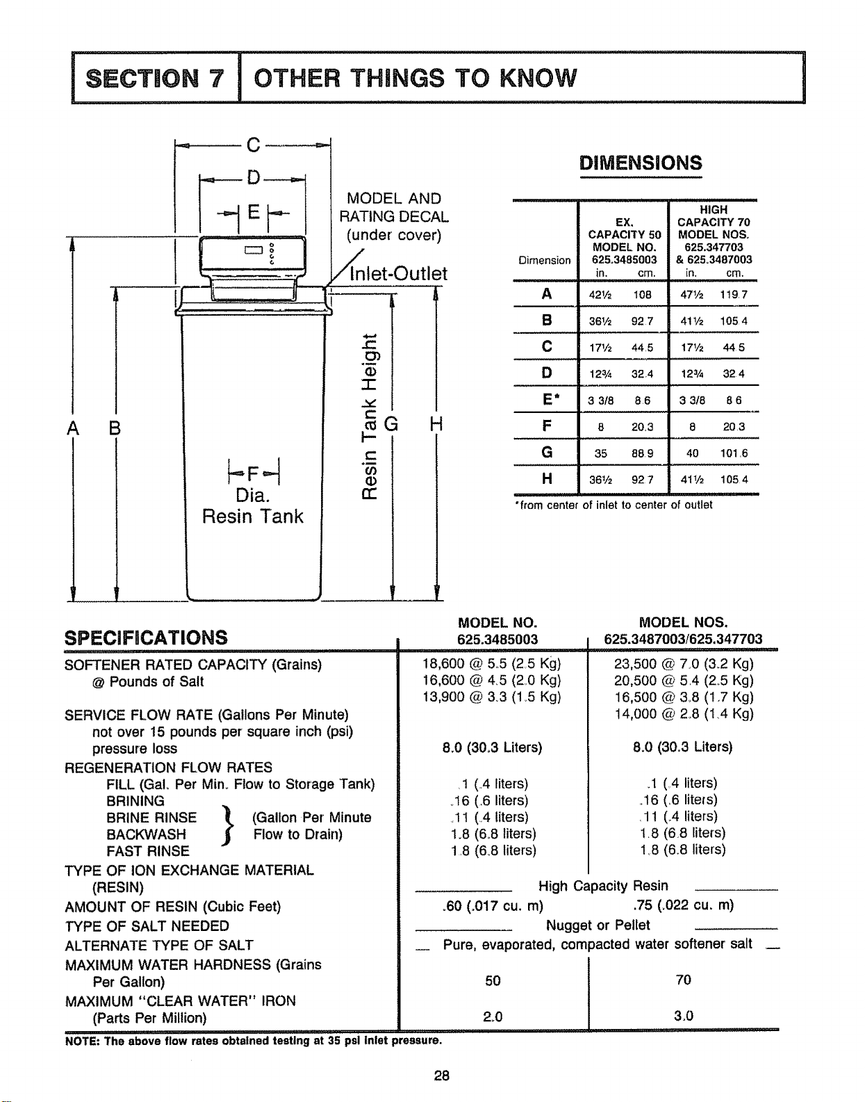
Dimensions and Specifications ................................ 28
Sweat Soldering Tips ........................................ 29
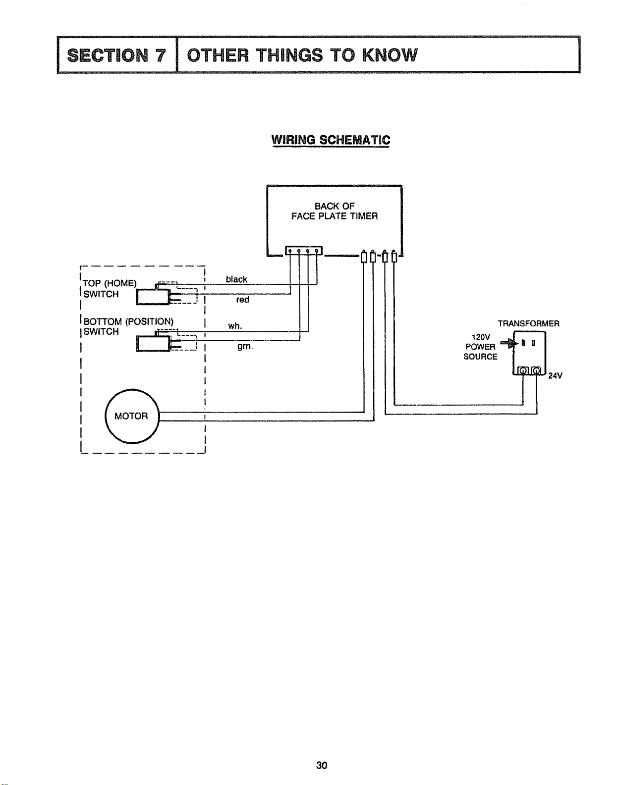
Wiring Connection Diagram ................................... 30
! I illll ¸ JllJlllllJllll,,i,uil,l,lllllll,ll,l,ll,,i u,l,i iil, lllll,llll,l,l,,, ii i
I UNPACKING, SAFETY GUIDES
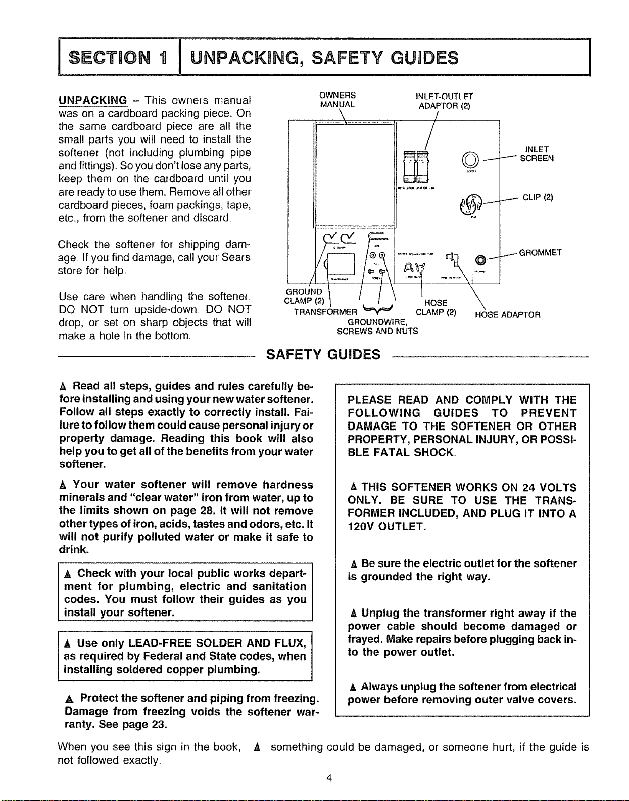
UNPACKING -This owners manual
was on a cardboard packing piece On
the same cardboard piece are al! the
small parts you will need to install the
softener (not including plumbing pipe
and fittings) _So you don't lose any parts,
keep them on the cardboard until you
are ready to use them. Remove all other
cardboard pieces, foam packings, tape,
etc., frorr_ the softener and discard.
Check the softener for shipping dam-
age If you find damage, call your Sears
store for help
Use care when handling the softene[
DO NOT turn upside-down. DO NOT
drop, or set on sharp objects that will
make a hole in the bottom
OWNERS
MANUAL
INLET-OUTLET
ADAPTOR (2)
!
/
GROUND
CLAMP (2) HO
TRANSFORMER _ CLAMP (2)
GROUNDWlRE,
SCREWS AND NUTS
INLET
SCREEN
CLIP (2)
...-- GROMMET
HOSE ADAPTOR
SAFETY GUIDES
I
A Read all steps, guides and rules carefully be-
fore installing and using your new water softener.
Follow all steps exactly to correctly install. Fai-
lure to follow them could cause personal injury or
property damage. Reading this book will also
help you to get all of the benefits from your water
softener,
A Your water softener will remove hardness
minerals and "clear water" iron from water, up to
the limits shown on page 28. It will not remove
other types of iron, acids, tastes and odors, etc. It
will not purify polluted water or make it safe to
drink.
A Check with your local public works depart-
ment for plumbing, electric and sanitation
codes. You must follow their guides as you
install your softener.
A Use only LEAD-FREE SOLDER AND FLUX,
as required by Federal and State codes, when
installing soldered copper plumbing.
A Protect the softener and piping from freezing.
Damage from freezing voids the softener war-
ranty. See page 23.
PLEASE READ AND COMPLY WITH THE
FOLLOWING GUIDES TO PREVENT
DAMAGE TO THE SOFTENER OR OTHER
PROPERTY, PERSONAL INJURY, OR POSSI-
BLE FATAL SHOCK.
A THIS SOFTENER WORKS ON 24 VOLTS
ONLY. BE SURE TO USE THE TRANS-
FORMER INCLUDED, AND PLUG IT INTO A
120V OUTLET.
_, Be sure the electric outlet for the softener
is grounded the right way.
A Unplug the transformer right away if the
power cable should become damaged or
frayed. Make repairs before plugging back in-
to the power outlet.
A Always unplug the softener from electrical
power before removing outer valve covers=
When you see this sign in the book, A something could be damaged, or someone hurt, if the guide is
not followed exactly.
HELPFULINFORMATION
If you knowlittle aboutplumbingskills,we sug-
gest you get a book on the subject..There are
many good books for do-it_yourselferson the
basicsof plumbing_Youcangeta lowcostbook
fromSears Plumbingand Heatingdepartments
thatwillhelpyou.Somebasicsweatsolderingtips
areon page29of thismanual..
i
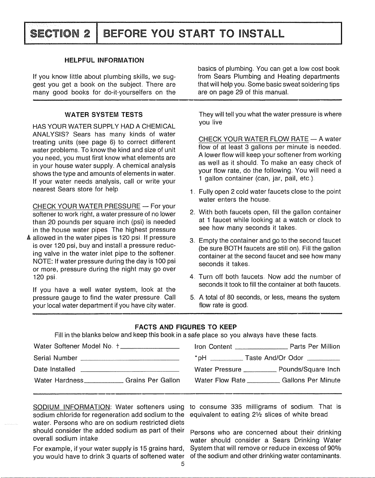
WATER SYSTEM TESTS
HAS YOUR WATER SUPPLY HAD A CHEMICAL
ANALYSIS? Sears has many kinds of water
treating units (see page 6) to correct different
water problems.. To know the kind and size of unit
you need, you must first know what elements are
in your house water supply, A chemical analysis
shows the type and amounts of elements in water.
If your water needs analysis, call or write your
nearest Sears store for help.
CHECK YOUR WATER PRESSURE -- For your
softener to work right, a water pressure of no tower
than 20 pounds per square inch (psi) is needed
in the house water pipes. The highest pressure
A allowed in the water pipes is 120 psL If pressure
is over 120 psi, buy and install a pressure reduc-
ing valve in the water inlet pipe to the softener..
NOTE: If water pressure during the day is 100 psi
or more, pressure during the night may go over
120 psi.
If you have a well water system, look at the
pressure gauge to find the water pressure. Call
your local water department if you have city water.
They will tell you what the water pressure is where
you live
.
34
.
CHECK YOUR WATER FLOW RATE -- A water
flow of at least 3 gallons per minute is needed°
A lower flow will keep your softener from working
as well as it should.. To make an easy check of
your flow rate, do the following° You will need a
1 gallon container (can, jar, pail, etc.)
Fully open 2 cold water faucets close to the point
water enters the house.
With both faucets open, fill the gallon container
at 1 faucet while looking at a watch or clock to
see how many seconds it takes_
Empty the container and go to the second faucet
(be sure BOTH faucets are still on).. Fill the gallon
container at the second faucet and see how many
seconds it takes_
Turn off both faucets., Now add the number of
seconds it took to fill the container at both faucets,.
A total of 80 seconds, or less, means the system
flow rate is good_
FACTS AND FIGURES TO KEEP
Fill in the blanks below and keep this book in a safe place so you always have these facts.
Water Softener Model No. t
Serial Number
Date Installed
Water Hardness
Grains Per Gallon
Iron Content Parts Per Million
*pH Taste And/Or Odor
Water Pressure PoundsfSquare Inch
Water Flow Rate Gallons Per Minute
SODIUM INFORMATION: Water softeners using
sodium chloride for regeneration add sodium to the
water. Persons who are on sodium restricted diets
should consider the added sodium as part of their
overall sodium intake
For example, if your water supply is 15 grains hard,
you would have to drink 3 quarts of softened water
5
to consume 335 milligrams of sodium That is
equivalent to eating 21/2 slices of white bread
Persons who are concerned about their drinking
water should consider a Sears Drinking Water
System that will remove or reduce in excess of 90%
of the sodium and other drinking water contaminants.

START TO iNSTALL I
WHERE TO INSTALL THE SOFTENER
Think of the following points as you choose a
place to put your softener. (See FIGo 1)..
,, Place as close as possible to the pressure tank
(well water) or water meter (city water-).
a Place as close as possible to a water drain such
as a floor drain, laundry tub, sump or standpipe°
A o Connect to the house main water pipe BEFORE
THE WATER HEATER. Ternperature of water'
going through the softener must not be more
than 120 F (49 C),.
• Keep outside faucets on hard water to save soft
water and salt.
_, o DO NOT install in a place where the softener
could freeze° Freeze damage voids the warranty
Ao
A@
,Ao
Ao
by Sears, Roebuck and Co. (See page 23).
Put the softener in a place water damage is least
likely to occur if it develops a leako Sears or the
manufacturer will not repair or pay for-water'
damage.
A 120V electric outlet, to plug the transformer
into, is needed within 10 feet of the softener (the
softener has a 10 foot power cable). Be sure the
outlet and transformer are in an inside place,
to protect from wet weather.
When installing in an outside location, you must
take the steps necessary to assure the softener,
installation plumbing, and wiring, are as well
protected from the elements, contamination,
vandalism, etc., as when installed indoors.
Keep the softener out of direct sunlighL The
sun's heat can melt plastic parts.
THE PROPER ORDER TO INSTALL WATER TREATING EQUIPMENT
(Shows sequence* of equipment only - seldom, if ever would all items be needed)
Sediment or
Taste & Odor
Ca.[rtridge
Hlter
c01dsoft
Phosphate
Feeder
"A}ways put the iron Filter before the
softener, the Taste & Odor Filter after the
softener, the Neutrafizer before an iron
Filter, etc, as shown
Taste & Water
Odor Softener
Fitter
PLAN HOW TO INSTALL YOUR SOFTENER
You must first decide how to run in and out pipes
to the softener. Look at your house main water pipe
at the point you will connect the softener, ts the pipe
soldered copper, glued plastic, or threaded galvaniz-
ed or brass? What is the pipe size? What kind of pipe
and fittings is it easiest for you to work with, and what
tools do you have?
6
Now look at the common plans for in and out piping
on pages 8 and 9. Select the drawing best for you
arid use it as a guide to plan what materials you will
need._ As you plan your in and out piping, keep in
mind the following check list.. Then get all the
materials you will need before you start.
BEFORE YOU START TO INSTALL
I
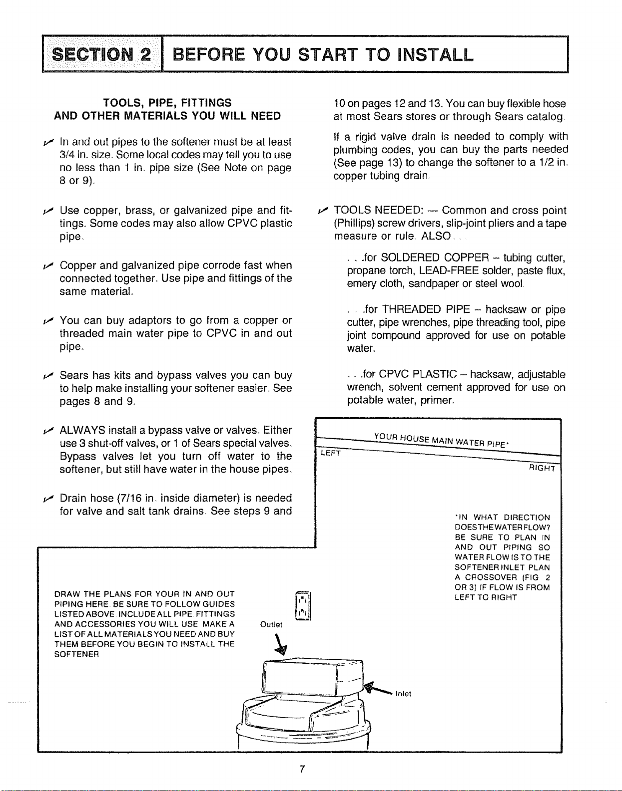
TOOLS, PIPE, FITTINGS
AND OTHER MATERIALS YOU WILL NEED
v"
in and out pipes to the softener must be at least
3/4 in. size.. Some local codes may tell you to use
no less than I in. pipe size (See Note on page
8 or 9)o
10 on pages 12 and l& You can buy flexible hose
at most Sears stores or through Sears catalog.
If a rigid valve drain is needed to comply with
plumbing codes, you can buy the parts needed
(See page 13) to change the softener to a 1/2 inn
copper tubing drain.
Use copper, brass, or galvanized pipe and fit-
ting& Some codes may also allow CPVC plastic
pipe.
_" Copper and galvanized pipe corrode fast when
connected together. Use pipe and fittings of the
same material
Ii' You can buy adaptors to go from a copper or
threaded main water pipe to CPVC in and out
pipe..
ii' Sears has kits and bypass valves you can buy
to help make installing your softener easier.. See
pages 8 and 9o
v"
ALWAYS install a bypass valve or valve& Either
use 3 shut-off valves, or 1 of Sears special valves,
Bypass valves let you turn off water to the
softener, but still have water in the house pipes,
11' Drain hose (7/16 in,. inside diameter) is needed
for valve and salt tank drains, See steps 9 and
DRAW THE PLANS FOR YOUR IN AND OUT
PIPING HERE BE SURE TO FOLLOW GUIDES
LISTEDABOVE INCLUDEALL PIPE FITTINGS
AND ACCESSORIES YOU WILL USE MAKE A Outlet
LIST OF ALL MATERIALS YOU NEED AND BUY %
THEM BEFORE YOU BEGIN TO INSTALL THE
SOFTENER
v" TOOLS NEEDED: -- Common and cross point
(Phillips) screw drivers, slip-joint pliers and a tape
measure or rule. ALSO ....
. °for SOLDERED COPPER - tubing cutter,
propane torch, LEAD-FREE solder, paste flux,
emery cloth, sandpaper or steel wool.
.... for THREADED PIPE - hacksaw or pipe
cutter, pipe wrenches, pipe threading tool, pipe
joint compound approved for use on potable
water°
oo°for CPVC PLASTIC - hacksaw, adjustable
wrench, solvent cement approved for use on
potable water, primer_
YOUR HOUSE MAIN WATER PIPE'
RJGH--T"
"IN WHAT DIRECTION
DOES THE WATER FLOW?
BE SURE TO PLAN IN
AND OUT PIPING SO
WATER FLOW tS TO THE
SOFTENER INLET PLAN
A CROSSOVER [FIG 2
OR 3) IF FLOW IS FROM
LEFT TO RIGHT
Inlet
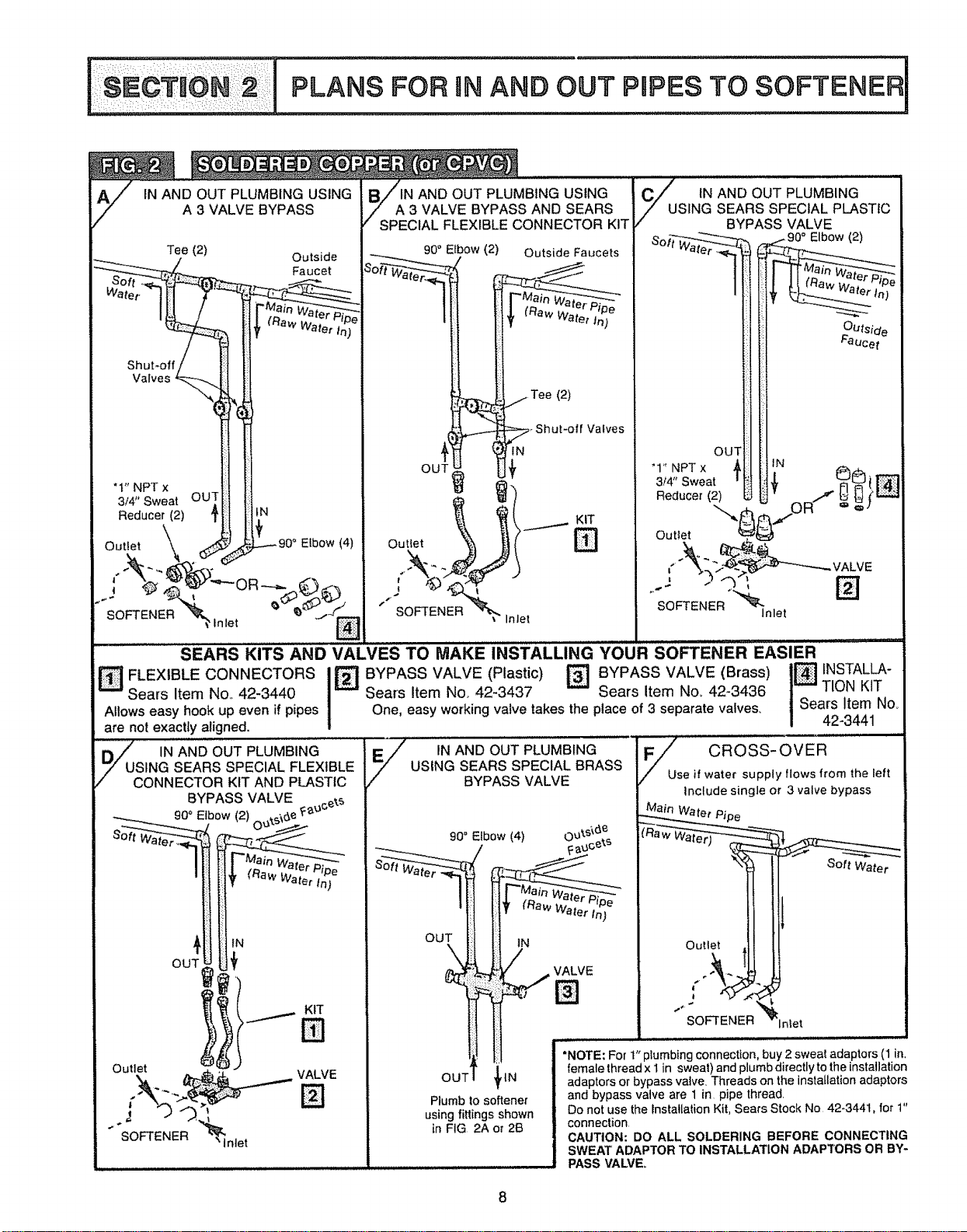
IN AND OUT PLUMBING USING
A 3 VALVE BYPASS
Tee (2)
Outside
Faucet
Shut-off
Valves
"t" NPT x
3/4" Sweat
Reducer (2)
Cutter
OU
iN
Elbow (4)
SOFTENER
N AND OUT PLUMBING USING
A 3 VALVE BYPASS AND SEARS
SPECIAL FLEXIBLE CONNECTOR KIT
90" Elbow (2) Outside Faucets
(2)
KIT
C_U' tN AND OUT PLUMBING
SING SEARS SPECIAL PLASTIC
BYPASS VALVE
I °
f _'b-
Outside
Faucet
OUT
'1" NPT x
3/4'° Sweat
!
Reducer (2)
IN
Outlet
/ALVE
SOFTENER
Inlet
_J_ ..... _ .......... J J . IIj IIII1[I
SE..SK,TS..OV. WS M.K ,.STA..,.GYOU.sorrE...E.S,E.
FLEXIBLE CONNECTORS I_ BYPASS VALVE (Plastic) _ BYPASS VALVE (Brass)
Sears Item No. 42-3440 Sears Item Nor 42-3437 Sears item Nor 42-3436
Allows easy hook up even if pipes One, easy working valve takes the place of 3 separate valves.
are not exactly aligned.
_C IN AND OUT PLUMBING
SING SEARS SPECIAL FLEXIBLE
ONNECTOR KIT AND PLASTIC
BYPASS VALVE _ce_._
___ g0'_Elbow (2) ..j?_s'_6e_:_'
-- er Pipe
I { (SawWate_tn)
IN
OUT i_
Outlet VALVE
N
IN AND OUT PLUMBING
USING SEARS SPECIAL BRASS
BYPASS VALVE
OUT _ _tN
Plumb to softener
using fittings shown
in FIG 2A or 2B
I_ NSTALLA-
TION KIT
Sears Item No_
42-3441
F//Z_u CROSS-OVER
se if water supply flows from the left
include single or 3 valve bypass
Soft Water
Outlet
j÷
SOFTENER
Inlet
*NOTE: For 1" plumbing connection, buy 2 swea! adaptors (1 in,
female thread x 1 in sweat) and plumb directly to the installation
adaptors or bypass vatve. Threads on the installation adaptors
and bypass valve are 1 in pipe thread.
Do not use the Installation Kit, Sears Stock No 42-3441, for t"
connection
CAUTION: 130 ALL SOLDERING BEFORE CONNECTING
SWEAT ADAPTOR TO INSTALLATION ADAPTORS OR BY-
PASS VALVE°
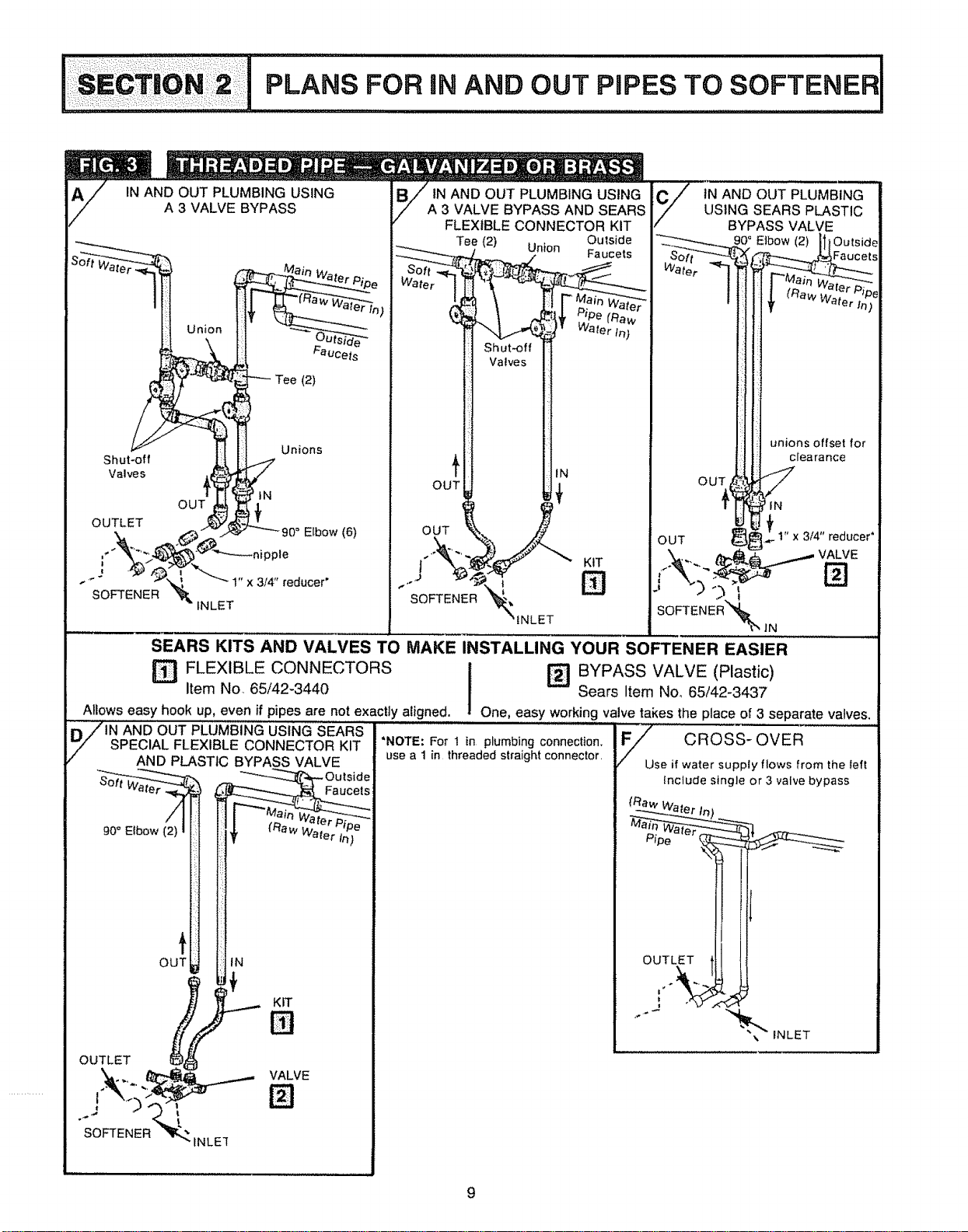
ic io. PL NSrO"'.DouTP,,,.
IN AND OUT PLUMBING USING
A 3 VALVE BYPASS
Union
Shut-off
Valves
OUTLET
I
SOFTENER
OUT
Unions
_NLET
tN
Elbow (6)
ppie
3t4" reducer'
IN AND OUT PLUMBING USING
A 3 VALVE BYPASS AND SEARS
FLEXIBLE CONNECTOR KIT
Outside
Tee (2) Un}on Faucets
OUT
OUT
SOFTENER
Shut.off
Valves
IN
KIT
N
SEARS KITS AND VALVES TO MAKE INSTALLING YOUR SOFTENER EASIER
I BYPASS VALVE (Plastic)
FLEXIBLEItemNo, 65/42-3440CONNECTORS _ Sears Item No_ 65/42-3437
Allows easy hook up, even if pipes are not exactly aligned. One, easy working valve takes the place of 3 separate valves.
_71N AND OUT PLUMBING USING SEARS
_" SPECIAL FLEXIBLE CONNECTOR KIT *NOTE: For 1 in plumbing connection.
-- AND PLASTIC BYPASS VALVE use a 1 in threaded straight connector.
OUTL_ H_N
U_ KIT
SOFTENER_ fNLE_I
F_ CROSS-OVER
se if water supply flows from the lef!
Include single or 3 valve bypass
OUTLET
i SECTION 3 I STEP BY STEP GU,DES TO iNsTALL I
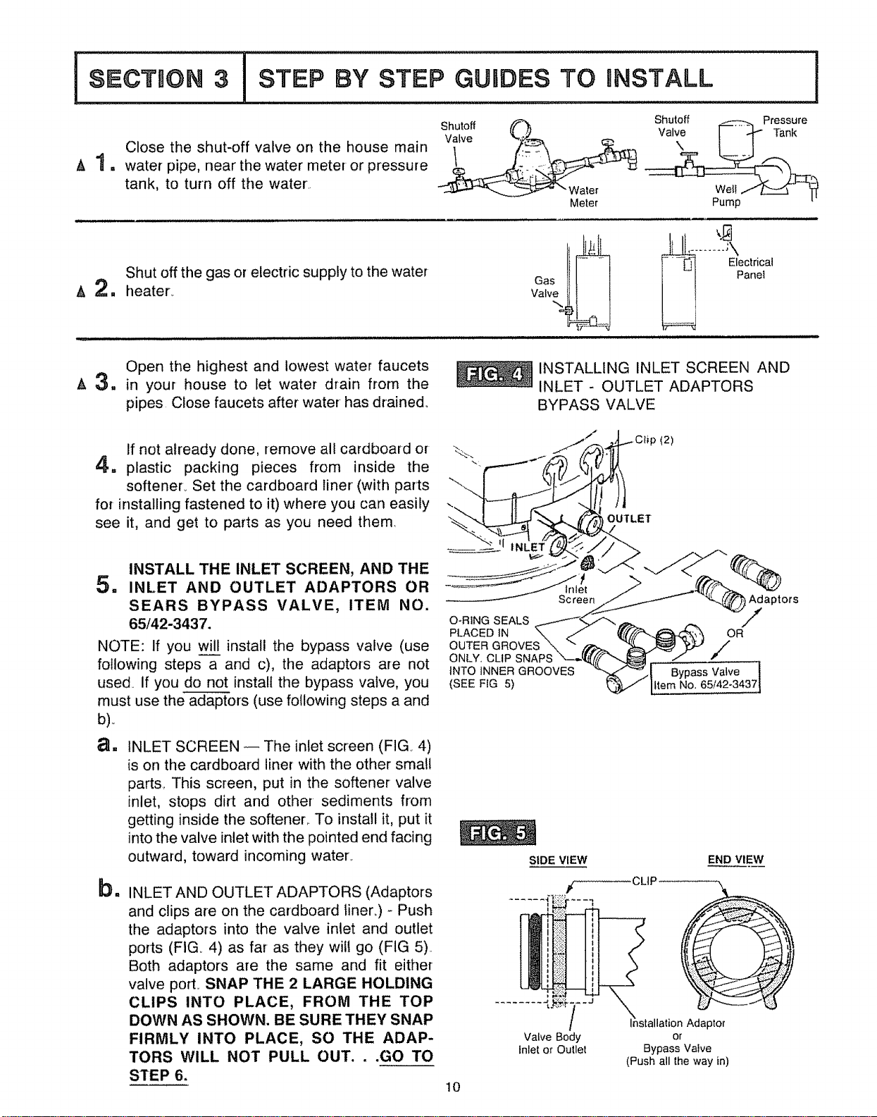
Close the shut-off valve on the house main
,& 1 = water pipe, near the water meter or pressure
tank, to turn off the water
Shutoff
Valve
Meter
Shutoff _Pressure
Pump L.
Shut off the gas or electric supply to the water
& 2. heater..
tlII....... ca,
_J_ Electri
Panel
Open the highest and lowest water faucets
A 3. in your house to let water drain from the
pipes Close faucets after water has drained°
INSTALLING INLET SCREEN AND
INLET - OUTLET ADAPTORS
BYPASS VALVE
If not already done, remove all cardboard or
4. plastic packing pieces from inside the
softener_ Set the cardboard liner (with parts
for installing fastened to it) where you can easily
see it, and get to parts as you need them.
INSTALL THE INLET SCREEN, AND THE
5,, INLET AND OUTLET ADAPTORS OR
SEARS BYPASS VALVE, ITEM NO.
65/42-3437.
NOTE: If you will install the bypass valve (use
following steps a and c), the adaptors are not
used. if you do not install the bypass valve, you
must use the adaptors (use following steps a and
b),
a. INLET SCREEN -- The inlet screen (FIG 4)
is on the cardboard liner with the other sma!l
parts., This screen, put in the softener valve
inlet, stops dirt and other sediments from
getting inside the softener.. To install it, put it
into the valve inlet with the pointed end facing
outward, toward incoming water.
bli
INLET AND OUTLET ADAPTORS (Adaptors
and clips are on the cardboard liners) - Push
the adaptors into the valve inlet and outlet
ports (FIG. 4) as far as they will go (FIG 5)..
Both adaptors are the same and fit either
valve port° SNAP THE 2 LARGE HOLDING
CLIPS INTO PLACE, FROM THE TOP
DOWN AS SHOWN. BE SURE THEY SNAP
FIRMLY INTO PLACE, SO THE ADAP-
TORS WILL NOT PULL OUT...GO TO
STEP 6.
_"_ J..._C_ip (2)
Sc ree_.__- _ Adaptors
PLACED_N ._ <f_ (t_('_?_._'_,_ OR
OUTERGROVES\ " _. _ _' /
'CNNT_3YiNCNL/PSGNRoovEAPS"__1' _passValve "1
(SEE FIG 5) _.._,.'¢ _ttem No, 65/42-3437J
SIDE VIEW
/
END VIEW
10
/
Valve Body
Inlet o_ Outle!
_nstallation Adaptor
or
Bypass Vafve
(Push all the way in)
!
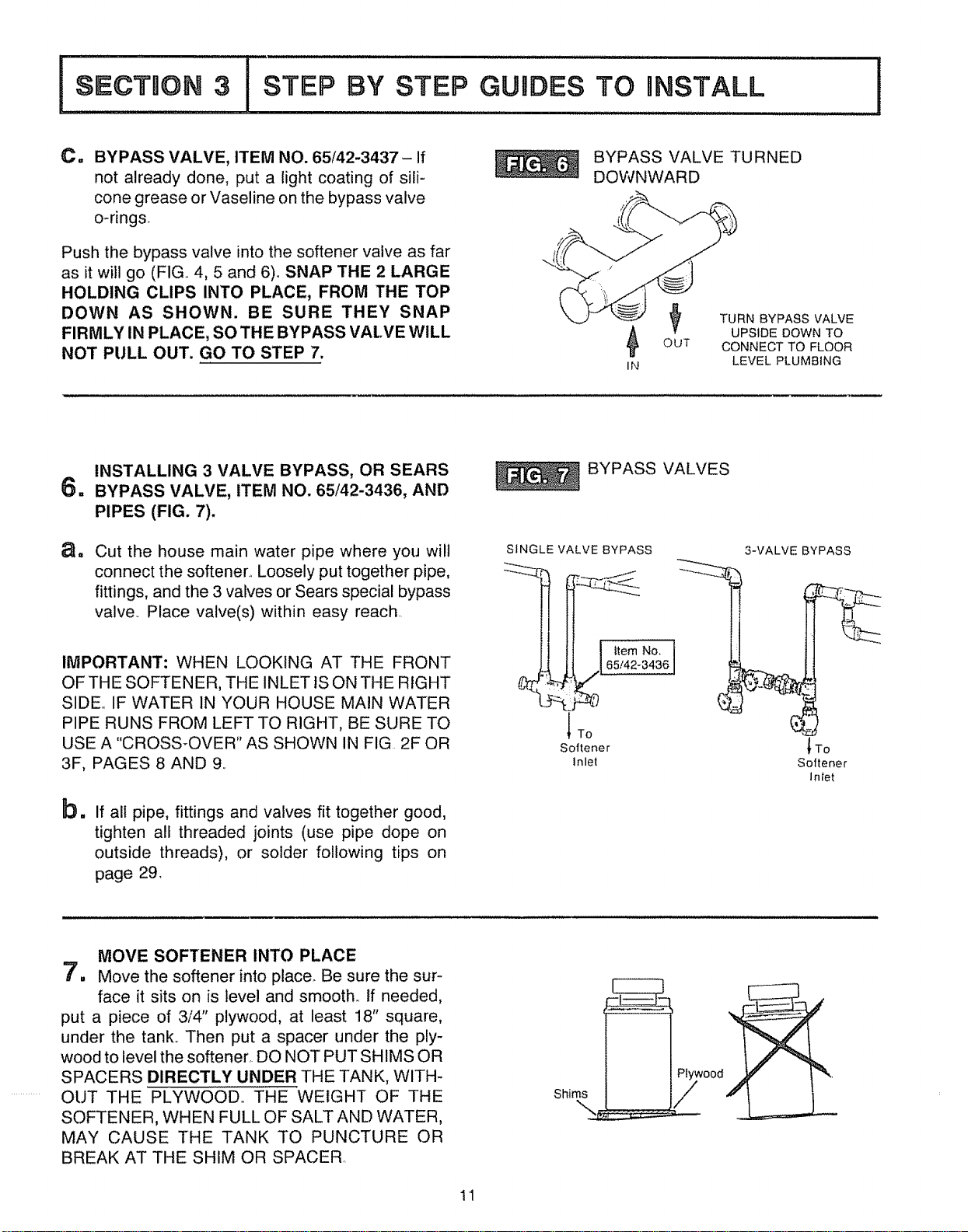
C. BYPASS VALVE, ITEM NO. 65/42-3437- If
not already done, put a light coating of sili-
cone grease or Vaseline on the bypass valve
o-rings.
Push the bypass valve into the softener valve as far
as it will go (FIG. 4, 5 and 6)° SNAP THE 2 LARGE
HOLDING CLIPS INTO PLACE, FROM THE TOP
DOWN AS SHOWN. BE SURE THEY SNAP
FIRMLY IN PLACE, SO THE BYPASS VALVE WiLL
NOT PULL OUT. GO TO STEP 7.
BYPASS VALVE TURNED
DOWNWARD
l_ TURN BYPASS VALVE
UPSIDE DOWN TO
OUT CONNECT TO FLOOR
iN LEVEL PLUMBING
1=
aa
INSTALLING 3 VALVE BYPASS, OR SEARS
BYPASS VALVE, ITEM NO. 65/42-3436, AND
PIPES (FIG. 7).
Cut the house main water pipe where you will
connect the softener° Loosely put together pipe,
fittings, and the 3 valves or Sears special bypass
valve.. Place valve(s) within easy reach.
IMPORTANT: WHEN LOOKING AT THE FRONT
OF THE SOFTENER, THE INLET 1SON THE RIGHT
SIDE IF WATER IN YOUR HOUSE MAIN WATER
PIPE RUNS FROM LEFT TO RIGHT, BE SURE TO
USE A "CROSS-OVER '' AS SHOWN IN FIG 2F OR
3F, PAGES 8 AND 9.
bm
If all pipe, fittings and valves fit together good,
tighten all threaded joints (use pipe dope on
outside threads), or solder following tips on
page 29.
BYPASS VALVES
SINGLE VALVE BYPASS
| 65/42-34361
Softener
lnlet
3-VALVE BYPASS
_To
Softener
Inter
MOVE SOFTENER INTO PLACE
7, Move the softener into place. Be sure the sur-
face it sits on is level and smooth., tf needed,
put a piece of 3/4" plywood, at least 18" square,
under the tank_ Then put a spacer under the ply-
wood to level the softener, DO NOT PUT SHIMS OR
SPACERS DIRECTLY UNDER THE TANK, WITH-
............ OUT THE PLYWOOD,, THE WEIGHT OF THE
SOFTENER, WHEN FULL OF SALT AND WATER,
MAY CAUSE THE TANK TO PUNCTURE OR
BREAK AT THE SHIM OR SPACER,
Shims
,,_wood
11
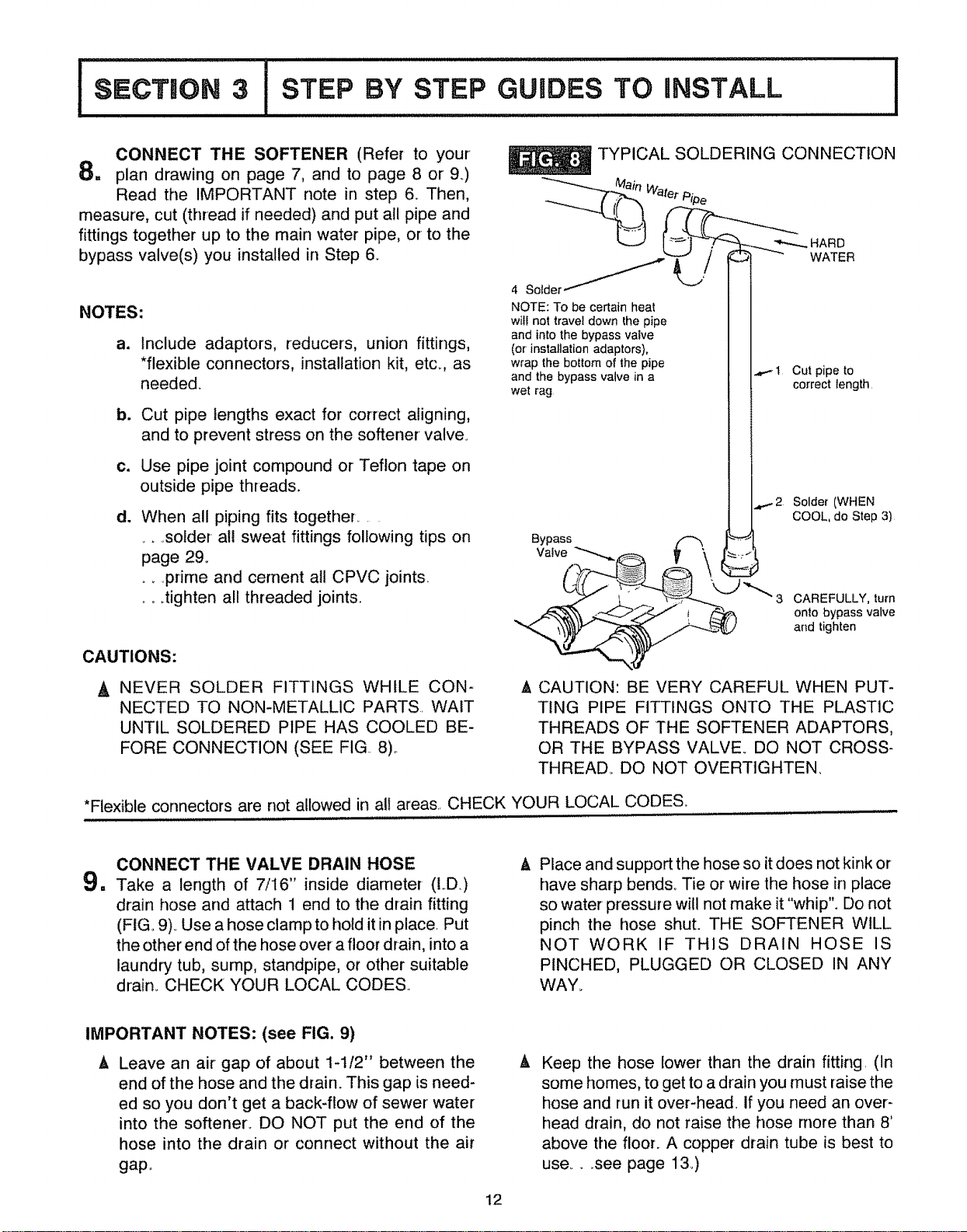
CONNECT THE SOFTENER (Refer to your
8= plan drawing on page 7, and to page 8 or 9)
Read the IMPORTANT note in step 6. Then,
measure, cut (thread if needed) and put all pipe and
fittings together up to the main water pipe, or to the
bypass valve(s) you installed in Step &
NOTES:
a_
b_
c_
dl
Include adaptors, reducers, union fittings,
*flexible connectors, installation kit, etc. as
needed.
Cut pipe lengths exact for correct aligning,
and to prevent stress on the softener valve°
Use pipe joint compound or Teflon tape on
outside pipe threads.
When all piping fits together....
..... solder all sweat fittings following tips on
page 29.,
_ ,prime and cement at! CPVC joints
.._.tighten all threaded joints.
TYPICAL SOLDERING CONNECTION
tWate*_P_pe
NOTE: To be certain heat I I
wiU not travel down _he pipe I I
and into the bypass valve I I
(or installation adaptors), [ I
wrap the bottom of the pipe I I ..........
and the bypass valve in a t I_r'__r" _u_._u^,_,
wet rag [ i _,u-_L.__,_uu,,
ll
I I.,_..-2 Solder (WHEN
J [ COOL, do Step 3)
Bypass _'_[
Valve
"k,._ _ 3 CAREFULLY, turn
onto bypass valve
and tighten
CAUTIONS:
NEVER SOLDER FITTINGS WHILE CON-
NECTED TO NON-METALLIC PARTS. WAIT
UNTIL SOLDERED PIPE HAS COOLED BE-
FORE CONNECTION (SEE FIG.. 8)..
& CAUTION: BE VERY CAREFUL WHEN PUT-
TING PIPE FITTINGS ONTO THE PLASTIC
THREADS OF THE SOFTENER ADAPTORS,
OR THE BYPASS VALVE DO NOT CROSS-
THREAD_ DO NOT OVERTtGHTEN,
*Flexible connectors are not allowed in all areas.. CHECK YOUR LOCAL CODES.
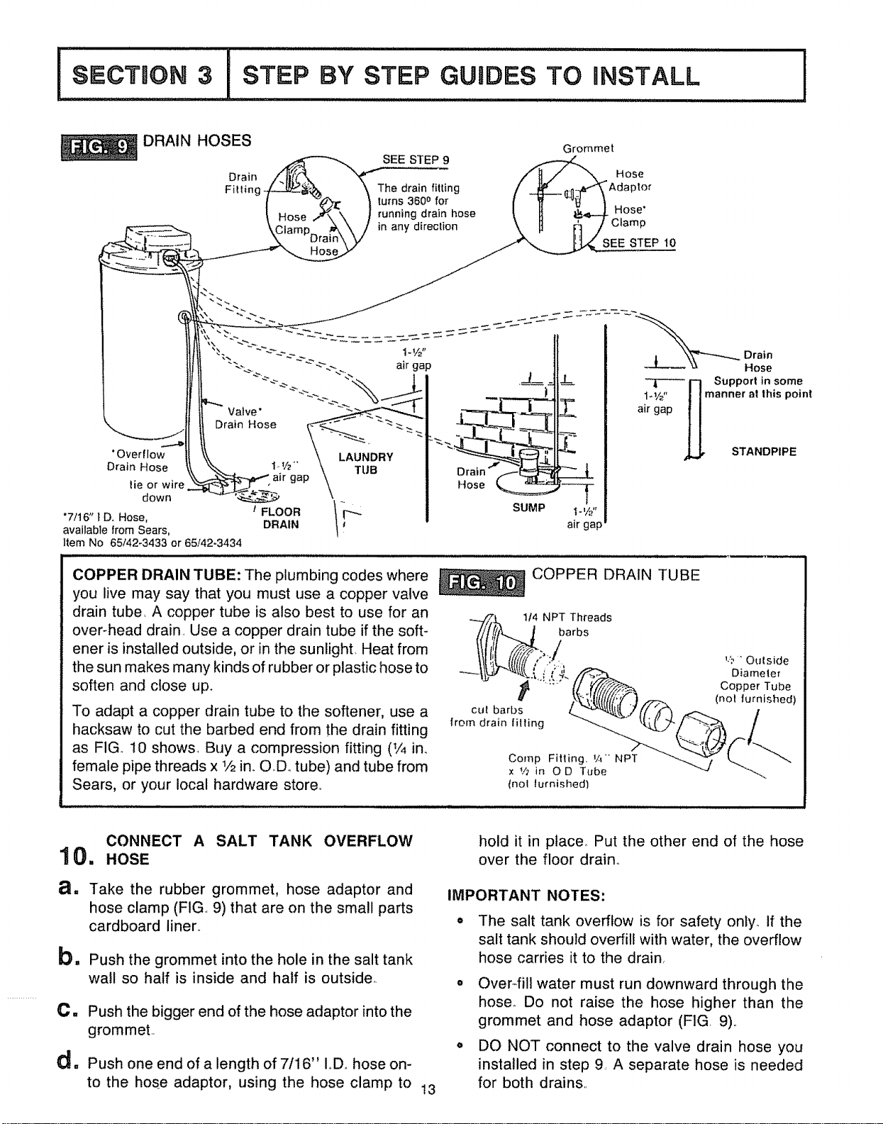
CONNECT THE VALVE DRAIN HOSE
9. Take a length of 7/i6" inside diameter (LD)
drain hose and attach 1 end to the drain fitting
(FIGo 9)° Use a hose clamp to hold it in place Put
the other end of the hose over a floor drain, into a
laundry tub, surnp, standpipe, or other suitable
drain. CHECK YOUR LOCAL CODES
A, Place and support the hose so it does not kink or
have sharp bend& Tie or wire the hose in place
so water pressure will not make it"whip". Do not
pinch the hose shut. THE SOFTENER WILL
NOT WORK IF THIS DRAIN HOSE IS
PINCHED, PLUGGED OR CLOSED IN ANY
WAY.
IMPORTANT NOTES: (see FIG. 9)
A Leave an air gap of about 1-1/2" between the
end of the hose and the drain. This gap is need-
ed so you don't get a back-flow of sewer water
into the softener. DO NOT put the end of the
hose into the drain or connect without the air
gap,.
& Keep the hose lower than the drain fitting. (In
some homes, to get to a drain you must raise the
hose and run it over-head If you need an over-
head drain, do not raise the hose more than 8'
above the floor. A copper drain tube is best to
use .... see page 13.)
12
SECTION 3 i STEP BY STEP GUIDES TO nNSTALL
I
DRAIN HOSES Grommet
SEE STEP 9
Drain Hose
Filling, The drain fitting "Adaptor
lurns 3600 for
running drain hose Hose'
;lamPD r in any direction
a
STEP 10
- _ __"__ Drain
Hose
-_ El Support in some
I_Z' _1 manner at this point
air gap I!
,L_ STANDPIPE
COPPER DRAIN TUBE: The plumbing codes where
you live may say that you must use a copper valve
drain tube. A copper tube is also best to use for an
over-head drain. Use a copper drain tube if the soft-
ener is installed outside, or in the sunlight. Heat from
the sun makes many kinds of rubber or plastic hose to
soften and close up_
To adapt a copper drain tube to the softener, use a
hacksaw to cut the barbed end from the drain fitting
as FIG. 10 shows. Buy a compression fitting (V4 in.
female pipe threads x V2 in. OD. tube) and tube from
Sears, or your local hardware store..
COPPER DRAIN TUBE
-_//_ j114NPT Threads
barbs
' "_'"" {/ _////_/_ Copper Tube
u _',_.I_((I(!'!F.].._-_-. (.ol tur°ished)
cu[ barbs /.__7(_ _'_ _ /
from drain filling _ _,_-/ -_-._ /
t-..
x _h in OD Tube ---u
(nol lumished)
CONNECT A SALT TANK OVERFLOW
1 0. HOSE
a. Take the rubber grommet, hose adaptor and
hose clamp (FIG 9) that are on the small parts
cardboard liner..
b= Push the grommet into the hole in the salt tank
wall so half is inside and half is outside,.
C. Push the bigger end of the hose adaptor into the
grommet..
d= Push one end of a length of 7116" IoD. hose on-
to the hose adaptor, using the hose clamp to 13
hold it in ptace_ Put the other end of the hose
over the floor draino
IMPORTANT NOTES:
o The salt tank overflow is for safety only. if the
salt tank should overfill with water, the overflow
hose carries it to the drain,
,, OveFfill water must run downward through the
hose_ Do not raise the hose higher than the
grommet and hose adaptor (FIG 9),.
,, DO NOT connect to the valve drain hose you
installed in step 9_ A separate hose is needed
for both drains,
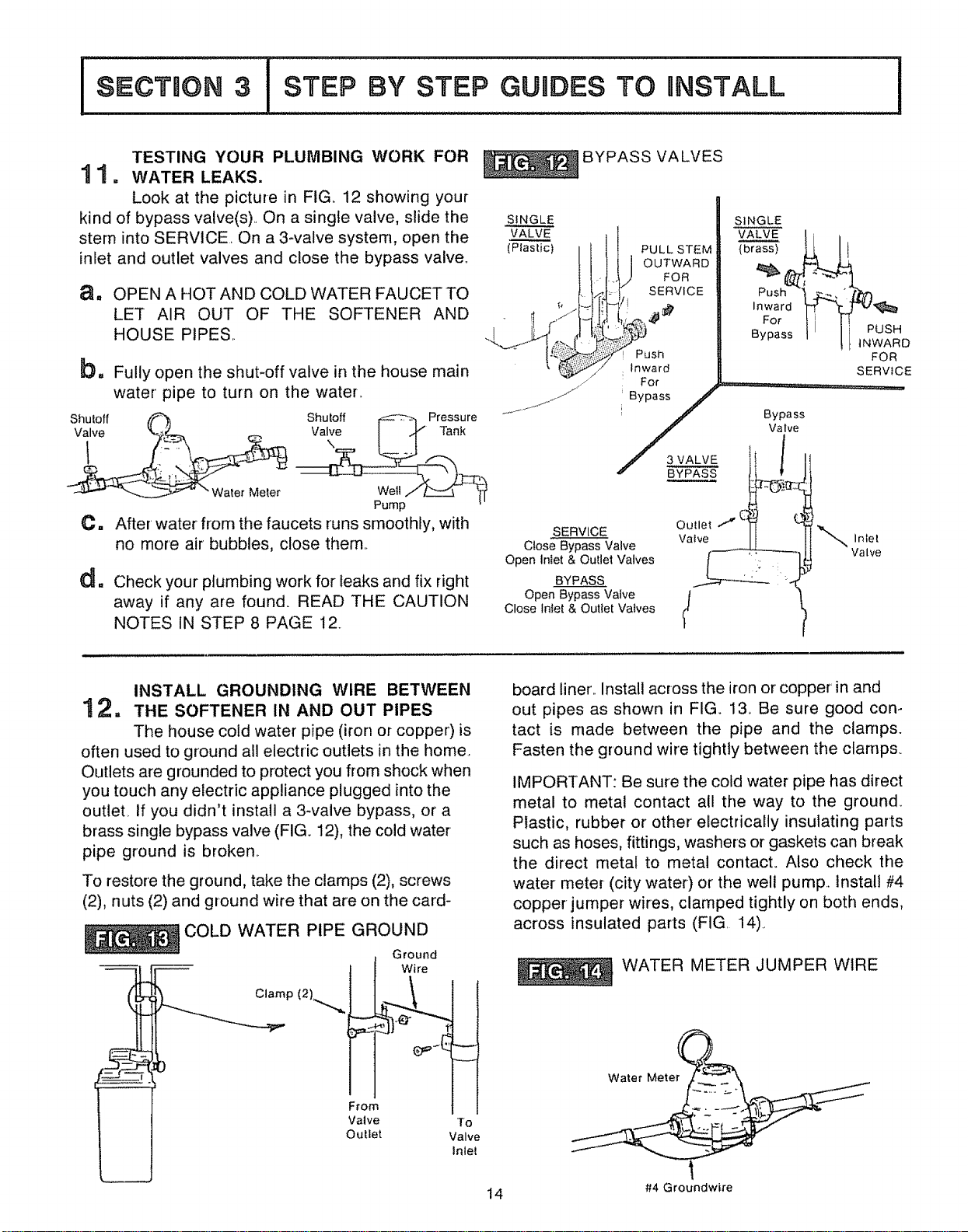
TESTING YOUR PLUMBING WORK FOR
1 1. WATER LEAKS.
Look at the picture in FIG i2 showing your
kind of bypass valve(s).. On a single valve, slide the
stern into SERV1CE. On a 3-valve system, open the
inlet and outlet valves and close the bypass valve..
au
bm
OPEN A HOT AND COLD WATER FAUCET TO
LET AIR OUT OF THE SOFTENER AND
HOUSE PIPES..
Shutoff (_
__._-_-_ -"Water Meter
0.
dlt
Fully open the shut-off valve in the house main
water pipe to turn on the water..
Shutoff t,_-_-_ Pressure
vat-L,
WeIt/z_=5 _f
Pump _'
After water from the faucets runs smoothly, with
no more air bubbles, close them..
Check your plumbing work for leaks and fix right
away if any are found. READ THE CAUTION
NOTES IN STEP 8 PAGE 12.
BYPASS VALVES
SINGLE
VALVE
(Plastic) PULL STEM
OUTWARD
FOR
SERVICE
Push
Inward
For
._ 3 VALVE
f
SINGLE
VALVE 1i
,Lk
Push '_
Inward _ '
For
Bypass
PUSH
INWARD
FOR
SERVICE
Bypass
Valve
SERVICE OuLlet /
Close Bypass Valve VaIve
Open Iniet& Outlet Valves
BYPASS
Open Bypass Valve t
Close Inlet & Outlet Vaives
Inlel
Valve
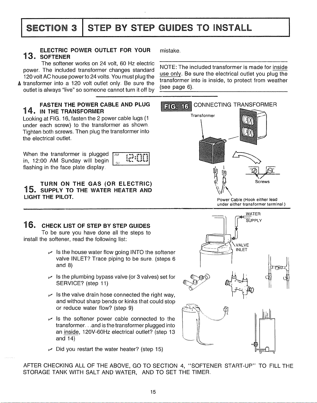
INSTALL GROUNDING WIRE BETWEEN
1 2, THE SOFTENER IN AND OUT PIPES
The house cold water pipe (iron or copper') is
often used to ground all electric outlets in the home.
Outlets are grounded to protect you from shock when
you touch any electric appliance plugged into the
outlet_ If you didn't install a 3-valve bypass, or a
brass single bypass valve (FIG. 12), the cold water
pipe ground is broken..
To restore the ground, take the clamps (2), screws
(2), nuts (2) and ground wire that are on the card-
COLD WATER PIPE GROUND
Clamp (2),.,,,,,,,,_
Ground
Wire
From
Valve To
Oullet Valve
Inle!
board liner.. Install across the iron or copper' in and
out pipes as shown in FIG. 13. Be sure good con-
tact is made between the pipe and the clamps.
Fasten the ground wire tightly between the clamps.
IMPORTANT: Be sure the cold water pipe has direct
metal to metal contact all the way to the ground.
Plastic, rubber or' other' electrically insulating parts
such as hoses, fittings, washers or gaskets can break
the direct metal to metal contact. Also check the
water meter (city water) or the well pump.. Install #4
copper jumper wires, clamped tightly on both ends,
across insulated parts (FIG. 14).
WATER METER JUMPER WIRE
Water Meter
14 #4 Groundwire
Ii
SECTION 3
STEP BY STEP GUmDES TO RNSTALL
,i
ELECTRIC POWER OUTLET FOR YOUR
13.
The softener works on 24 vott, 60 Hz electric
power° The included transformer changes standard
120 volt AC house power to 24 voltso "Youmust plug the
A transformer into a t20 volt outlet only. Be sure the
outlet is always "live" so someone cannot turn it off by
mistake.
NOTE: The included transformer is made for inside
use onlyo Be sure the electrical outlet you plug the
transformer into is inside, to protect from weather
(see page 6).
FASTEN THE POWER CABLE AND PLUG
"_4,, IN THE TRANSFORMER
Looking at FIGo 16, fasten the 2 power cable lugs (1
under each screw) to the transformer as shown.
Tighten both screws. Then plug the transformer into
the electrical outlet.
When the transformer is plugged 14M ,,,-, ,--,--,t
Iin, 12:00 AM Sunday will begin _;, ,,.. '..-,_ I
flashing in the face plate display.
TURN ON THE GAS (OR ELECTRIC)
15. SUPPLY TO THE WATER HEATER AND
LIGHT THE PILOT.
1 6, CHECK LIST OF STEP BY STEP GUIDES
To be sure you have done all the steps to
install the softener, read the following list:
,i Is the house water flow going INTO the softener
valve INLET? Trace piping to be sure,. (steps 6
and 8)
,t Is the plumbing bypass valve (or 3 valves) set for
SERVICE? (step 11)
Is the valve drain hose connected the right way,
and without sharp bends or kinks that could stop
or reduce water flow? (step 9)
Is the softener power cable connected to the
transformer_..and isthe transformer plugged into
an inside, 120V-60Hz electrical outlet? (step 13
and 14)
_, Did you restart the water heater? (step 15)
CONNECTING TRANSFORMER
/
Screws
Power Cable (Hook either lead
under either transformer terminal,)
WATER
Transformer
AFTER CHECKING ALL OF THE ABOVE, GO TO SECTION 4, "SOFTENER START-UP" TO FILL THE
STORAGE TANK WITH SALT AND WATER, AND TO SET THE TIMER.
15

!°ooTmo.31
WATER SOFTENER START=UP
!
SANITIZING THE WATER SOFTENER
1 = Care is taken at the factory to keep your water
softener clean and sanitary_ Materials used to
make the softener will not infect or contaminate your
water supply, and will not cause bacteria to form or
grow_ However, during shipping, storage, installing
and operating, bacteria could get into the water soft-
ener_ For' this reason, sanitizing as follows is
suggested '_when installing
1. Use a paii or hose to fill the salt storage tank with 3
gallons of water..
2. Pour about 3/4 ounce of common 525% house-
hold bleach (Clorox, Linco, Bo Peep, White Sail,
Eagle, etc.) into the brinew#!l, FIG.. 17.
ADD WATER AND FILL STORAGE
TANK WITH SALT
8rinewell
Cover
Water, about
3 gallons ..,......
_SrinewelF
3. Look at the faceplate and press the HOLD-RE-
CHARGE NOW button @, holding in until RCHG
begins to flash in the faceplate display, starting a
recharge. This first recharge, or regeneration '-'_,does
several things.
Tank
J
a. It draws the bleach into and through the water
softener, to sanitize it.
b. It fills the salt tank to the needed water level..
c. It gets all the air out of the resin tank.
d. It makes the resin bed (page 19) ready for serviceo
The regeneration takes about 2 hours. After that, soft
water goes into the house pipes. Then you can drain
hard water from the water heater'. Open a hot water
faucet until the water runs cold, then close faucet.
The tank refills with soft water. (It will take a few days
before your hot water is fully soft if you do not drain
the heater,)
CO Recommended by the Water Quality Association. On some water' supplies, the water softener may need
periodic disinfecting_
(_ RECHARGE and REGENERATION means the same.
SET THE TIMER
2, After the transformer is plugged into the electri-
cal outlet (step 14, pg. 15), 12:00 AM, SUn-
day began to flash in the time display. Set the time of
day and present day of week as follow&
A. SET TIME OF DAY
1. Press the PRESENT TIME AND DAY button []
once_ The hour display continues to flash.
2. Press the SET/CLEAR button [] until the present
hour of the day shows in the display. Be sure AM
for morning hours, or PM for afternoon and even-
ing hours show&
NOTE: Press SET/CLEAR and quickly release to
move the hour display ahead 1 at a time to the correct
hour. Or, hold the SET/CLEAR button to move the
display ahead 2 hours each second, to the correct
hour°
3. Press button [] once to steady the hour' display,
and minutes begin to flash. Repeat step A2 to set
the correct minute&
4. Press button [] again to steady the minute display
(day will begin flashing). Figure 19 shows the
timer set at 3:30 PM See step B to set the present
day_
16
!
[
Solid et_tg Automotl©
*m
display buttons
/ //
[_" PRESENT TIME AND DAY
[] RECHARGE T_ME
[] RECHARGEDAY
[] SET/CLEAR
[] ON,OFF VACATION
HOLD RECHARGE NOW
............... -J
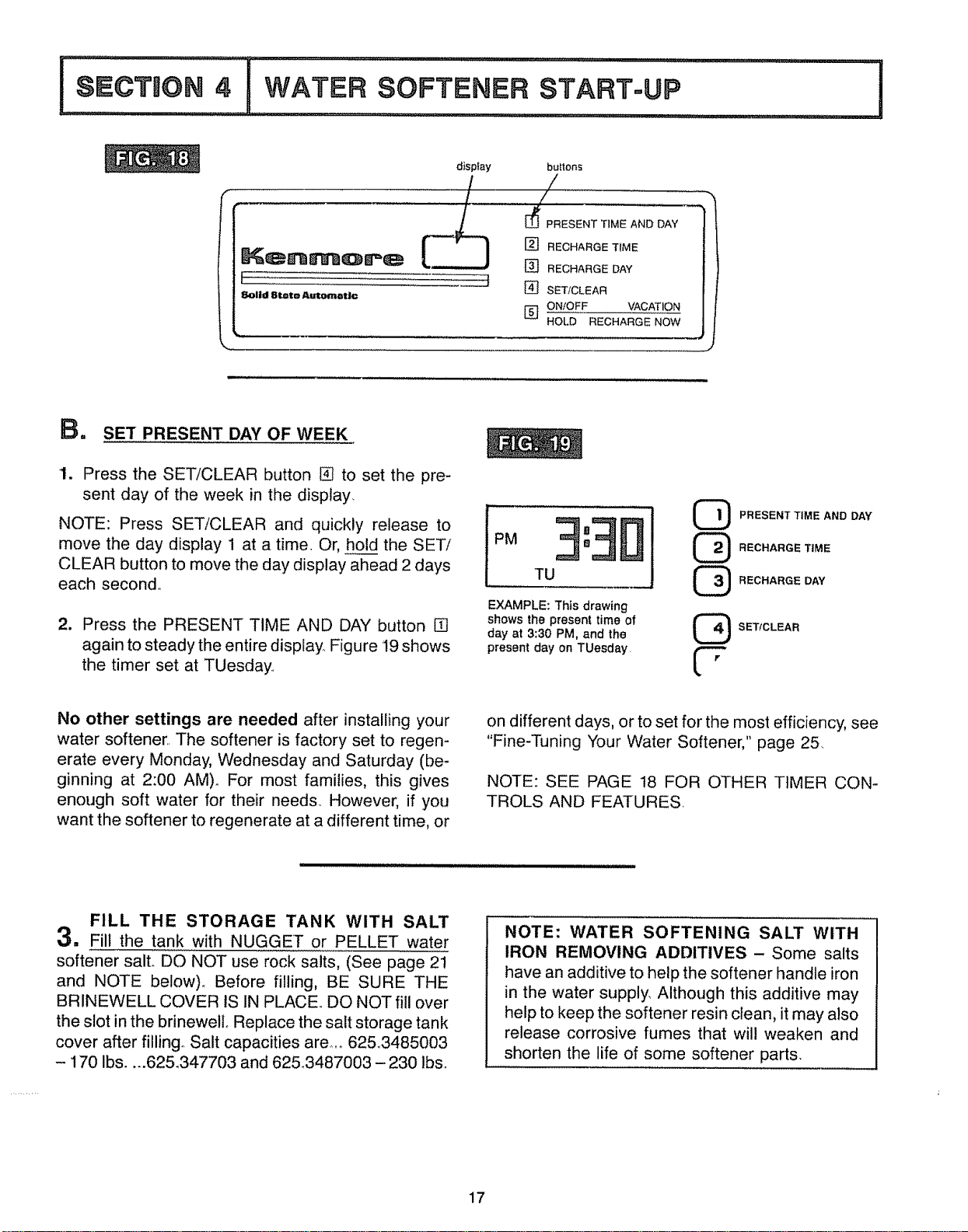
B. SET PRESENT DAY OF WEEK
1. Press the SET/CLEAR button [] to set the pre-
sent day of the week in the display.
NOTE: Press SET/CLEAR and quickly release to
move the day display 1 at a time. Or, hold the SET/
CLEAR button to move the day display ahead 2 days
each second,.
2. Press the PRESENT TIME AND DAY button []
again to steady the entire display.. Figure 19 shows
the timer set at TUesday.
PM
PRESENTTIME AND DAY
RECHARGE TIME
RECHARGE DAY
EXAMPLE: This drawing
shows the present time of
day at 3:30 PM, and the
L_2J
present day on TUesday f.----
L"
SET/CLEAR
No other settings are needed after installing your
water softener,, The softener is factory set to regen-
erate every Monday, Wednesday and Saturday (be-
ginning at 2:00 AM)_ For most families, this gives
enough soft water for their needs, However, if you
want the softener to regenerate at a different time, or
on different days. or to set for the most efficiency, see
"Fine-Tuning Your Water Softener," page 25,
NOTE: SEE PAGE t8 FOR OTHER TIMER CON-
TROLS AND FEATURES,
FILL THE STORAGE TANK WITH SALT
3. Fill the tank with NUGGET or PELLET water
softener salto DO NOT use rock salts, (See page 2t
and NOTE below), Before filling, BE SURE THE
BRINEWELL COVER IS IN PLACE,, DO NOT fill over
the slot in the brinewelL Replace the salt storage tank
cover after filling° Salt capacities are .....6253485003
- 170 Ibs .... 62&347703 and 62&3487003- 230 lb&
NOTE: WATER SOFTENING SALT WITH
IRON REMOVING ADDITIVES - Some salts
have an additive to help the softener handle iron
in the water supply, Although this additive may
help to keep the softener resin clean, it may also
release corrosive fumes that wil! weaken and
shorten the life of some softener parts,
17
HOW YOUR WATER SOFTENER WORKS
,t t,lt i,_,,
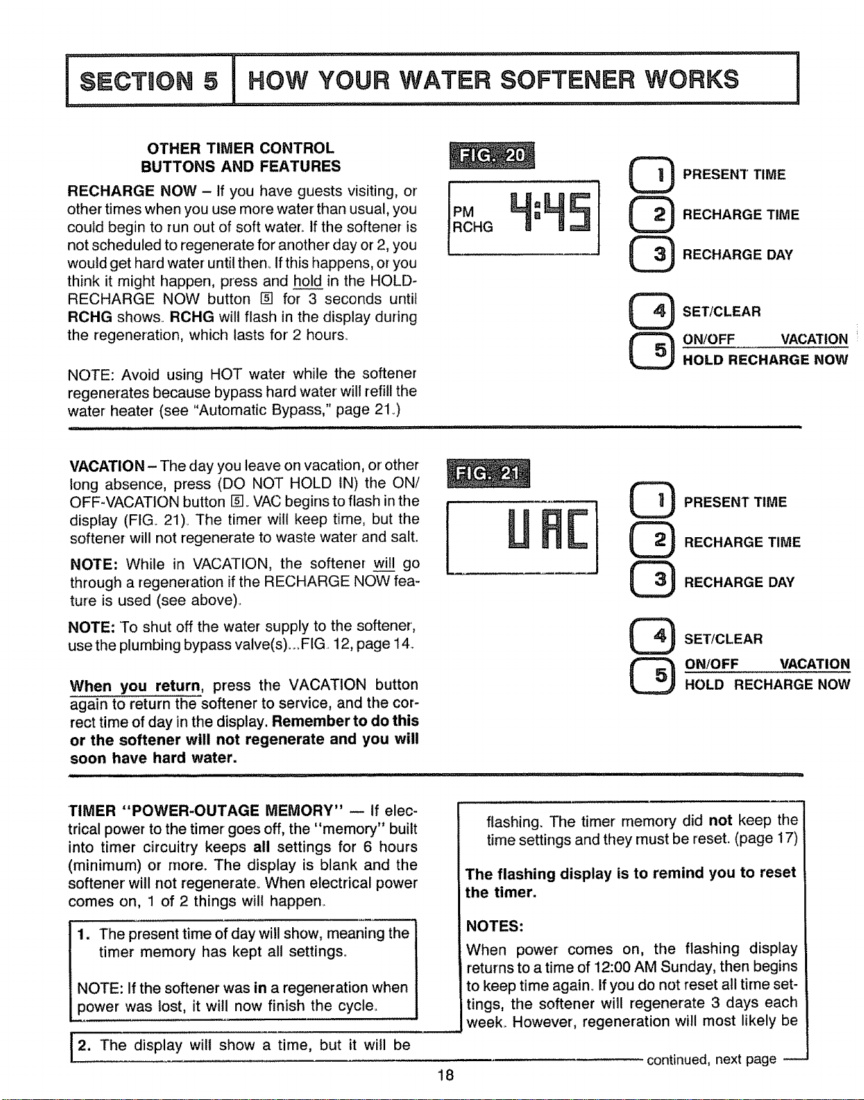
OTHER TIMER CONTROL
BUTTONS AND FEATURES
RECHARGE NOW - if you have guests visiting, or
other times when you use more water than usual, you
could begin to run out of soft water_ If the softener is
not scheduled to regenerate for another day or 2, you
would get hard water until then° If this happens, or you
think it might happen, press and hold in the HOLD-
RECHARGE NOW button [] for 3 seconds until
RCHG shows. RCHG will flash in the display during
the regeneration, which lasts for2 hours_
NOTE: Avoid using HOT water while the softener
regenerates because bypass hard water will refill the
water heater (see "Automatic Bypass," page 2! .)
H,LI5
@
@
@
PRESENT TIME
RECHARGE TIME
RECHARGE DAY
SET/CLEAR
ON/OFF VACATION
HOLD RECHARGE NOW
VACATION - The day you leave on vacation, or' other
long absence, press (DO NOT HOLD iN) the ON/
OFF-VACATION button []_ VAC begins to flash in the
display (FIG. 21)o The timer will keep time, but the
softener will not regenerate to waste water and salt.
NOTE: While in VACATION, the softener w go
through a regeneration if the RECHARGE NOW fea-
ture is used (see above)_
NOTE: To shut off the water supply to the softener,
use the plumbing bypass valve(s)_oFIG 12, page 14,
When you return, press the VACATION button
again to return the softener to service, and the cor-
rect time of day in the display. Remember to do this
or the softener will not regenerate and you will
soon have hard water.
@
@
@
PRESENT TIME
RECHARGE TIME
RECHARGE DAY
SET/CLEAR
ON!OFF VACATION
HOLD RECHARGE NOW
TIMER "POWER-OUTAGE MEMORY" -- If elec-
trical power to the timer goes off, the "memory" built
into timer circuitry keeps all settings for 6 hours
(minimum) or rnoreo The display is blank and the
softener will not regenerate. When electrical power
comes on, 1 of 2 things will happen_
1. The present time of day will show, meaning the
timer memory has kept all settings.
NOTE: If the softener was in a regeneration when
power was lost, it will now finish the cycle.
2. The display will show a time, but it will be
18
flashing. The timer memory did not keep the
time settings and they must be reset. (page 17)
The flashing display is to remind you to reset
the timer.
NOTES:
When power comes on, the flashing display
returns to a time of 12:00 AM Sunday, then begins
to keep time again. If you do not reset all time set-
tings, the softener will regenerate 3 days each
week.= However, regeneration will most likely be
continued, next page

!
-- continued -
on the wrong days and at the wrong time.,
If the softener was in a regeneration when power
went off, the valve will return to service position
without finishing the regeneration cycle. If your
water tastes salty,
, o.use RECHARGE NOW (see page 18) to start
another regeneration, or,, ,.
..o_,open 1 or more soft water faucets and allow to
run until the salt taste is gone_
SOFT WATER SERVICE, AND RECHARGE, OR REGENERATION
SERVICE
When the softener is giving you soft water, it is called
"Service". During service, hard water comes from
the house main water pipe into the softener. Inside
the softener resin tank is a bed made up of
thousands of tiny, plastic resin beads (FIGo 22). As
hard water passes through the bed, each bead
attracts and holds the hardness minerals. This is
called ion-exchanging, It is much like a magnet at-
tracting and holding metals. Water without the hard-
ness minerals (soft water) flows out of the softener
and into the house soft water pipes,
After a period of time, the resin beads become coated
with hardness minerals and they have to be cleaned.
This cleaning is called recharge, or regeneration°
WATER FLOW THROUGH THE
SOFTENER IN SERVICE
Soft Water
OUT
Resin Tank ,---,.
Salt Storage _
Tank
Hard Water
_N
.-..-- Resin Bed
RECHARGE OR REGENERATION
Regeneration is started at about 2:00 a_m. (factory
setting) by the timer_ It takes place in 5 stages or
cycles° These are:
%
58
@
FILL [_ BACKWASH
BRINING [_ FAST RINSE
BRINE RINSE
[] FILL: Salt, dissolved in water, is called brine,.
Brine is needed to clean the hardness minerals from
the resin beads° To make the brine, soft water flows
into the salt storage area during the fill cycle as
shown in FIG. 23.
The length of the fill cycle is t6 minutes, unless
another time is set when "Fine-Tuning", pages
25-27.
WATER FLOW THROUGH THE
SOFTENER IN FILL
Hard Water
IN
SoftWater
ti:==::=i_:ii=
:::i: i:::i
Salt
/ Storage Tank
(salt not shown)
19
WORKS
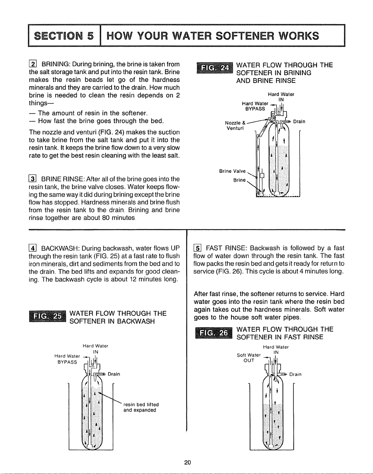
E_] BRINING: During brining, the brine istaken from
the salt storage tank and put into the resin tank. Brine
makes the resin beads let go of the hardness
minerals and they are carried to the drain. How much
brine is needed to clean the resin depends on 2
things--
The amount of resin in the softener'..
How fast the brine goes through the bed.,
The nozzle and venturi (FIG. 24) makes the suction
to take brine from the salt tank and put it into the
resin tank. It keeps the brine flow down to a very slow
rate to get the best resin cleaning with the least salt,
[_] BRINE RINSE: After all of the brine goes into the
resin tank, the brine valve closes. Water keeps flow-
ing the same way it did during brining except the brine
flow has stopped° Hardness minerals and brine flush
from the resin tank to the drain,. Brining and brine
rinse together are about 80 minutes.
WATER FLOW THROUGH THE
SOFTENER IN BRINING
AND BRINE RINSE
Hard Water
IN
Hard Water _,_ .h
Nozzre&.1---- /,/'_I_
Venturi ! (,
ii
Brine Valve _,
B.oe\
Drain
[] BACKWASH: During backwash, water flows UP
through the resin tank (FIG,. 25) at a fast rate to flush
iron minerals, dirt and sediments from the bed and to
the drain_ The bed lifts and expands for good clean-
ing The backwash cycle is about 12 minutes long.
WATER FLOW THROUGH THE
SOFTENER IN BACKWASH
Hard Water
BYPASS
Hard Water
IN
Drain
resin bed lifted
and expanded
_] FAST RINSE: Backwash is followed by a fast
flow of water down through the resin tank.. The fast
flow packs the resin bed and gets it ready for return to
service (FIG. 26). This cycle is about 4 minutes long,.
After fast rinse, the softener returns to service. Hard
water goes into the resin tank where the resin bed
again takes out the hardness minerals° Soft water
goes to the house soft water pipes.
WATER FLOW THROUGH THE
SOFTENER IN FAST RINSE
Hard Water
IN
Soft Water
OUT __.
Drain
2O
!°ooTiO,,l,ow oo.
WATER SOFTENER
AUTOMATIC BYPASS
During the brining, brine rinse and backwash cycles
of regeneration, HARD water goes through the
softener valve and to the house pipes.. If a faucet is
turned on, hard water is there for your needs°
However, you should not use HOT water, if possible,
because the water heater will refill with hard water.
The softener regenerates from 2:00 AM (factory set-
ting) to about 4:00 AM, a time when not much water
is used.
Depending on your working hours, you may choose
to select a different regeneration starting time. To
make this change see instructions for setting the time
of regeneration on page 25°
I°,o,,o"°i............................
CARE YOUR
i II ,,,1111,11111111,1,111,11_,L
,11 1,1,1,11,,,iill i i ,,,,,in, ,i,, ii,,,i
SOFTENER !
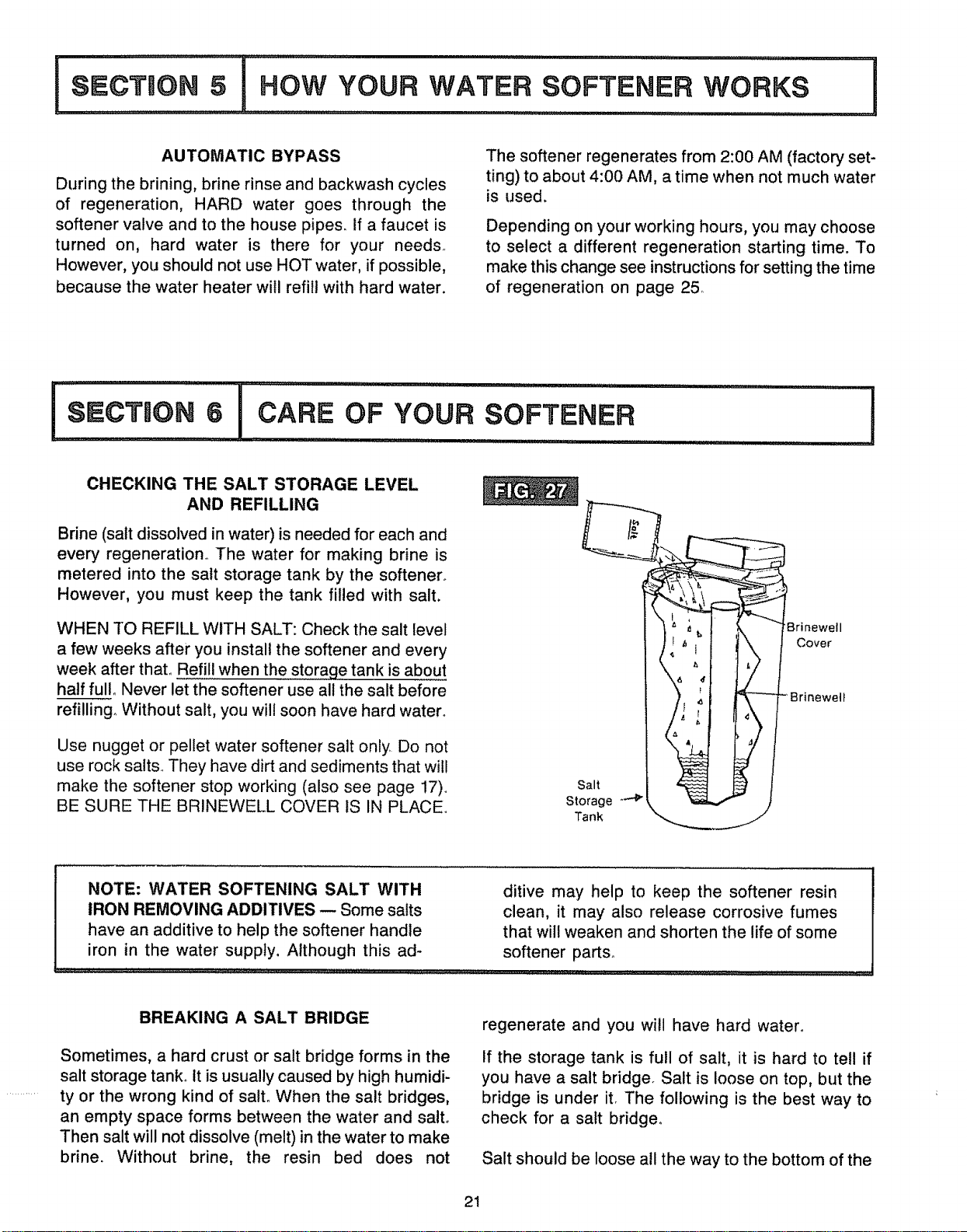
CHECKING THE SALT STORAGE LEVEL
AND REFILLING
Brine (salt dissolved in water) is needed for each and
every regeneration.. The water for making brine is
metered into the salt storage tank by the softener°
However, you must keep the tank filled with salt.
WHEN TO REFILL WITH SALT: Check the salt level
a few weeks after you install the softener and every
week after that. Refill when the storaqe tank is about
half full. Never let the softener use all the salt before
refilling° Without salt, you will soon have hard water°
Use nugget or pellet water softener salt only Do not
use rock salts. They have dirt and sediments that will
make the softener stop working (also see page 17),.
BE SURE THE BRINEWELL COVER IS IN PLACE.
Salt
Storage -_"P
Tank
Brinewell
Cover
NOTE: WATER SOFTENING SALT WITH ditive may help to keep the softener resin
IRON REMOVING ADDITIVES-- Some salts clean, it may also release corrosive fumes
have an additive to help the softener handle that will weaken and shorten the life of some
iron in the water supply, Although this ad- softener parts°
BREAKING A SALT BRIDGE
Sometimes, a hard crust or salt bridge forms in the
salt storage tank_ It is usually caused by high humidi-
ty or the wrong kind of salto When the salt bridges,
an empty space forms between the water and salto
Then salt will not dissolve (melt) in the water to make
brine. Without brine, the resin bed does not
regenerate and you will have hard water.
if the storage tank is full of salt, it is hard to tell if
you have a salt bridge. Salt is loose on top, but the
bridge is under ito The following is the best way to
check for a salt bridge,.
Salt should be loose all the way to the bottom of the
21
°lc oFYou.
SOFTENER
I
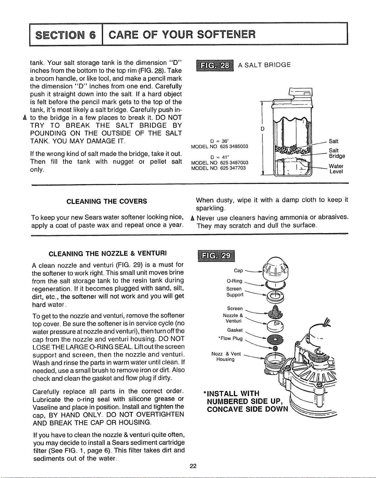
A
tank. Your salt storage tank is the dimension "D"
inches from the bottom to the top rim (FIG. 28). Take
a broom handle, or like tool, and make a pencil mark
the dimension "D" inches from one end. Carefully
push it straight down into the salt. If a hard object
is felt before the pencil mark gets to the top of the
tank, it's most likely a salt bridge. Carefully push in-
to the bridge in a few places to break it. DO NOT
TRY TO BREAK THE SALT BRIDGE BY
POUNDING ON THE OUTSIDE OF THE SALT
TANK.. YOU MAY DAMAGE IT_
if the wrong kind of salt made the bridge, take it out.
Then fill the tank with nugget or pellet salt
only.
A SALT BRIDGE
D = 36"
MODEL NO 625 3485003
D = 41"
MODEL NO, 625 3487003
MODEL NO 625 347703
Salt
Satt
----- Bridge
Water
Level
CLEANING THE COVERS
To keep your' new Sears water softener looking nice,
apply a coat of paste wax and repeat once a year°
When dusty, wipe it with a damp cloth to keep it
sparkling.
A Never use cleaners having ammonia or abrasives.
They may scratch and dull the surface_
...................... i
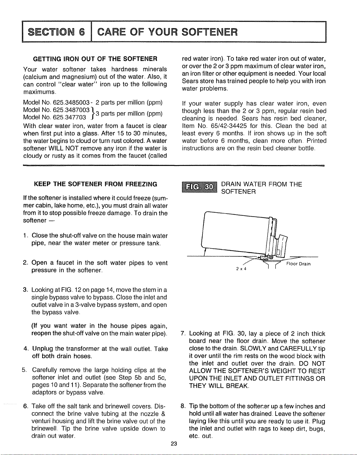
CLEANING THE NOZZLE & VENTURI
A clean nozzle and venturi (FIG. 29) is a must for
the softener to work right. This srnall unit moves brine
from the salt storage tank to the resin tank during
regeneration. If it becomes plugged with sand, silt,
dirt, etc., the softener will not work and you will get
hard water.
To get to the nozzle and venturi, remove the softener
top cover. Be sure the softener is in service cycfe (no
water pressure at nozzle and venturi), then turn off the
cap from the nozzle and venturi housing. DO NOT
LOSE THE LARG E O-RING SEAL. Lift out the screen
support and screen, then the nozzle and venturi.
Wash and rinse the parts in warm water until clean. If
needed, use a small brush to remove iron or dirt° Also
check and clean the gasket and flow plug if dirty.
Carefully replace atl parts in the correct order.
Lubricate the o-ring seal with silicone grease or
Vaseline and place in position. Install and tighten the
cap, BY HAND ONLY. DO NOT OVERTIGHTEN
AND BREAK THE CAP OR HOUSING°
tf you have to clean the nozzle & venturi quite often,
you may decide to install a Sears sediment cartridge
filter' (See FIG. 1, page 6). This filter takes dirt and
sediments out of the water.
22
O-Ring
Screen
Support
Screen ,______
Nozzle &
Ventud
Gasket
Plug
"Flow "_"_-_ O
Nozz & Vent ___ ,,_
Housing
*INSTALL WITH
NUMBERED SIDE UP,
CONCAVE SIDE DOWN
GETTINGIRON OUT OF THE SOFTENER
Your water softener takes hardness minerals
(calcium and magnesium) out of the water.. Also, it
can control "clear water" iron up to the following
maximums.
Model No. 625.3485003- 2 parts per million (ppm)
Model No.
625.3487003
"11
._3 parts per million (ppm)
Model Noo 625..347703
With clear water iron, water from a faucet is clear
when first put into a glass. After 15 to 30 minutes,
the water begins to cloud or turn rust colored,. A water
softener WILL NOT remove any iron if the water is
cloudy or rusty as it comes from the faucet (called
red water iron), To take red water iron out of water,
or over the 2 or 3 ppm maximum of clear water iron,
an iron filter or other equipment is needed Your local
Sears store has trained people to help you with iron
water problems°
If your water supply has clear water iron, even
though less than the 2 or 3 ppm, regular resin bed
cleaning is needed, Sears has resin bed cleaner,
Item No.. 65/42-34425 for this,. Clean the bed at
least every 6 months, If iron shows up in the soft
water before 6 months, clean more often Printed
instructions are on the resin bed cleaner bottle.
KEEP THE SOFTENER FROM FREEZING
If the softener is installed where it could freeze (sum-
mer cabin, lake home, etc.), you must drain all water
from it to stop possible freeze damage.. To drain the
softener
1. Close the shut-off valve on the house main water
pipe, near the water meter or pressure tank,
2o Open a faucet in the soft water pipes to vent
pressure in the softener..
DRAIN WATER FROM THE
SOFTENER
2x4
_rain
3_
5_
4_
........... ,,
Looking at FIG. 12 on page 14, move the stem in a
single bypass valve to bypass,. Close the inlet and
outlet valve in a 3-valve bypass system, and open
the bypass valve..
(If you want water in the house pipes again,
reopen the shuboff valve on the main water pipe)..
Unplug the transformer at the wall outlet° Take
off both drain hoses,.
Carefully remove the large holding clips at the
softener inlet and outlet (see Step 5b and 5c,
pages 10 and 11 ). Separate the softener from the
adaptors or bypass valve,.
Take off the salt tank and brinewe!l covers. Dis-
connect the brine valve tubing at the nozzle &
venturi housing and lift the brine valve out of the
brinewell. Tip the brine valve upside down to
drain out water.
23
7_
Looking at FIG. 30, lay a piece of 2 inch thick
board near the floor drain. Move the softener
close to the drain.. SLOWLY and CAREFULLY tip
it over until the rim rests on the wood block with
the inlet and outlet over the drain. DO NOT
ALLOW THE SOFTENER'S WEIGHT TO REST
UPON THE INLET AND OUTLET FITTINGS OR
THEY WILL BREAK_
8. Tip the bottom of the softener up a few inches and
hold until all water has drained,. Leave the softener
laying like this until you are ready to use it. Plug
the inlet and outlet with rags to keep dirt, bugs,
etc. out.
BEFORE YOU CALL FOR SERVICE
HELPFUL HINTS CHECKLIST...TO HELP YOU SAVE MONEY
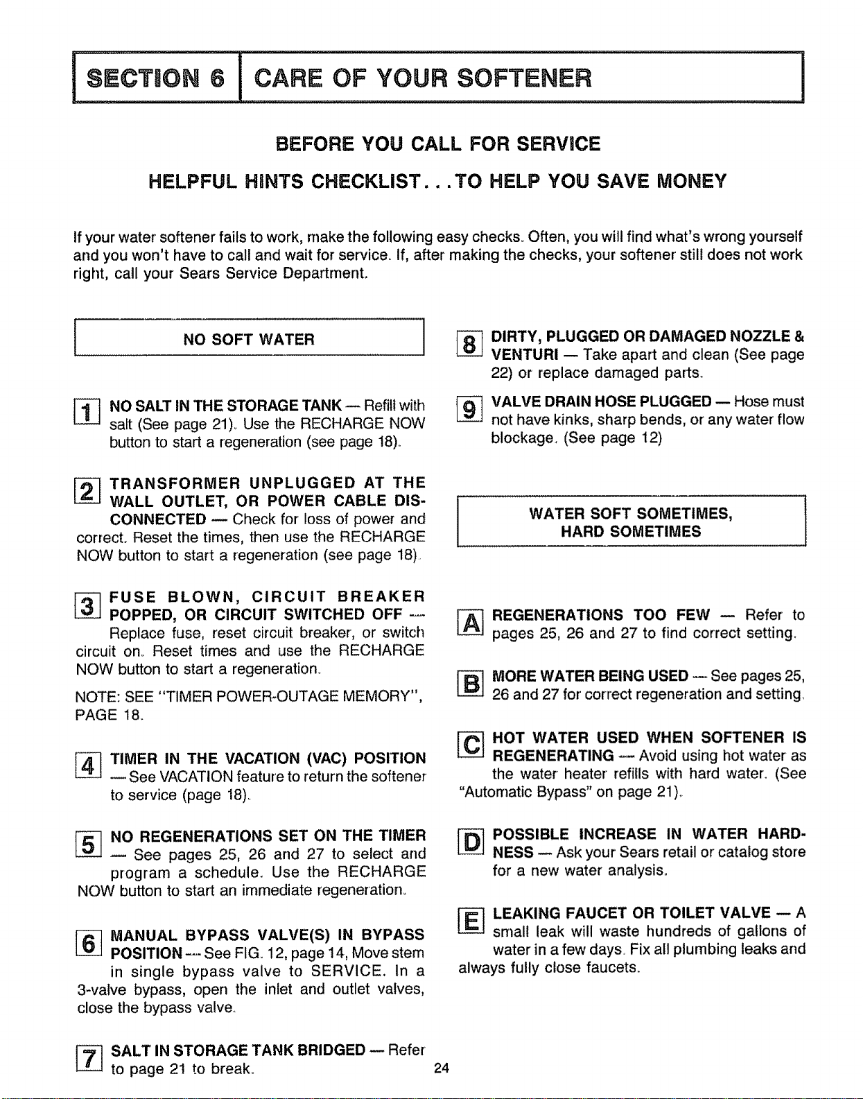
If your water softener fails to work, make the following easy checks° Often, you will find what's wrong yourself
and you won't have to call and wait for service. If, after making the checks, your softener' still does not work
right, call your Sears Service Department,
I NO SOFT WATER i
%
NO SALT IN THE STORAGE TANK -- Refill with
salt (See page 21)., Use the RECHARGE NOW
button to start a regeneration (see page 18)..
t_ DIRTY, PLUGGED OR DAMAGED NOZZLE &
VENTURI -- Take apart and clean (See page
22) or replace damaged parts.
_] VALVE DRAIN HOSE PLUGGED -- Hose must
not have kinks, sharp bends, or' any water flow
blockage. (See page 12)
_ TRANSFORMER UNPLUGGED AT THE
WALL OUTLET, OR POWER CABLE DIS- i
CONNECTED -- Check for loss of power and
I
correct. Reset the times, then use the RECHARGE
NOW button to start a regeneration (see page 18).
WATER SOFT SOMETIMES,
HARD SOMETIMES
_ FUSE BLOWN, CIRCUIT BREAKER
POPPED, OR CIRCUIT SWITCHED OFF ---
Replace fuse, reset circuit breaker, or switch
circuit ono Reset times and use the RECHARGE
NOW button to start a regeneration.
NOTE: SEE "TIMER POWER-OUTAGE MEMORY",
PAGE 18.
_ TIMER IN THE VACATION (VAC) POSITION
See 'vACATION feature to return the softener
to service (page 18)_
"Automatic Bypass" on page 21)..
REGENERATIONS TOO FEW -- Refer to
pages 25, 26 and 27 to find correct setting.
MORE WATER BEING USED -- See pages 25,
26 and 27 for' correct regeneration and setting,
HOT WATER USED WHEN SOFTENER IS
REGENERATING -- Avoid using hot water as
the water heater refifls with hard water. (See
NO REGENERATIONS SET ON THE TIMER
See pages 25, 26 and 27 to select and
program a schedule. Use the RECHARGE
NOW button to start an immediate regeneration_
-] MANUAL BYPASS VALVE(S) IN BYPASS
POSITION -- See FIG. 12, page 14, Move stem
in single bypass valve to SERVICE. In a
3-valve bypass, open the inlet and outlet valves,
close the bypass valve.
[_ POSSIBLE INCREASE IN WATER HARD-
NESS _ Ask your Sears retail or catalog store
for a new water analysis,
_ LEAKING FAUCET OR TOILET VALVE _ A
small leak will waste hundreds of gallons of
water in a few days Fix all plumbing leaks and
always fully close faucets.
_] SALT IN STORAGE TANK BRIDGED -- Refer
to page 21 to break, 24
I SECTmGN
OTHER THINGS TO
KNOW I
HOW TO "FINE-TUNE" YOUR SOFTENER
It is not hard to fine-tune your softener, but it does
take a few minutes of your time to do it right. You
may save up to 500 pounds or more of salt each year
with proper tuning. Read the following carefully.
To have soft water all the time, the softener must
regenerate, or recharge a certain number of times in
each 7 day period_ How many times to regenerate
(set on the timer) depends on 3 things.
1. The number of people in your home -- tells you
how much water is used,.
2. The grains per gallon (GPG) hardness of your
water supply m listed on your water analysis
report o..see page 5,
3. How much salt is used each regeneration - deter-
mined by the length of the fill cycle ..... see page
27.
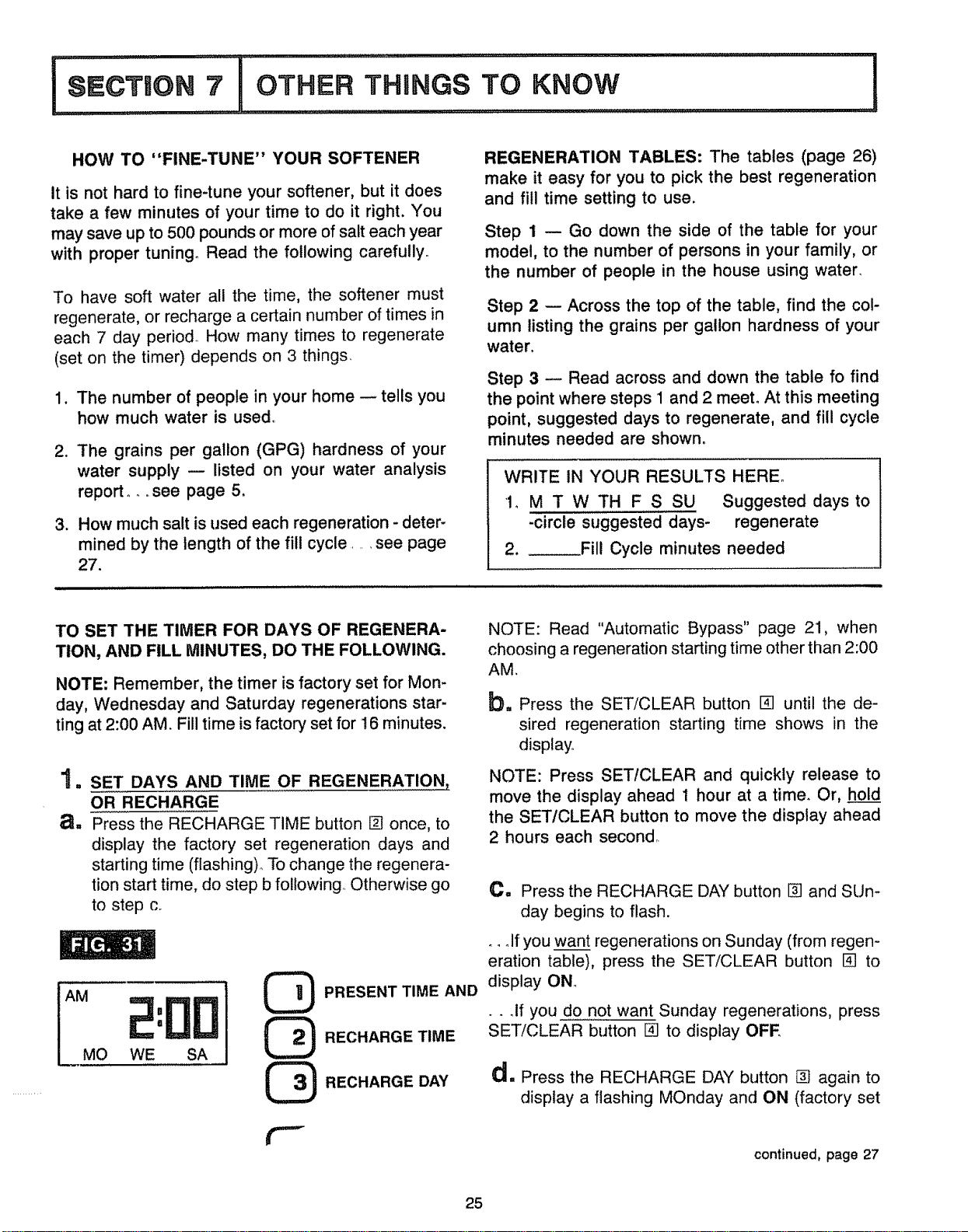
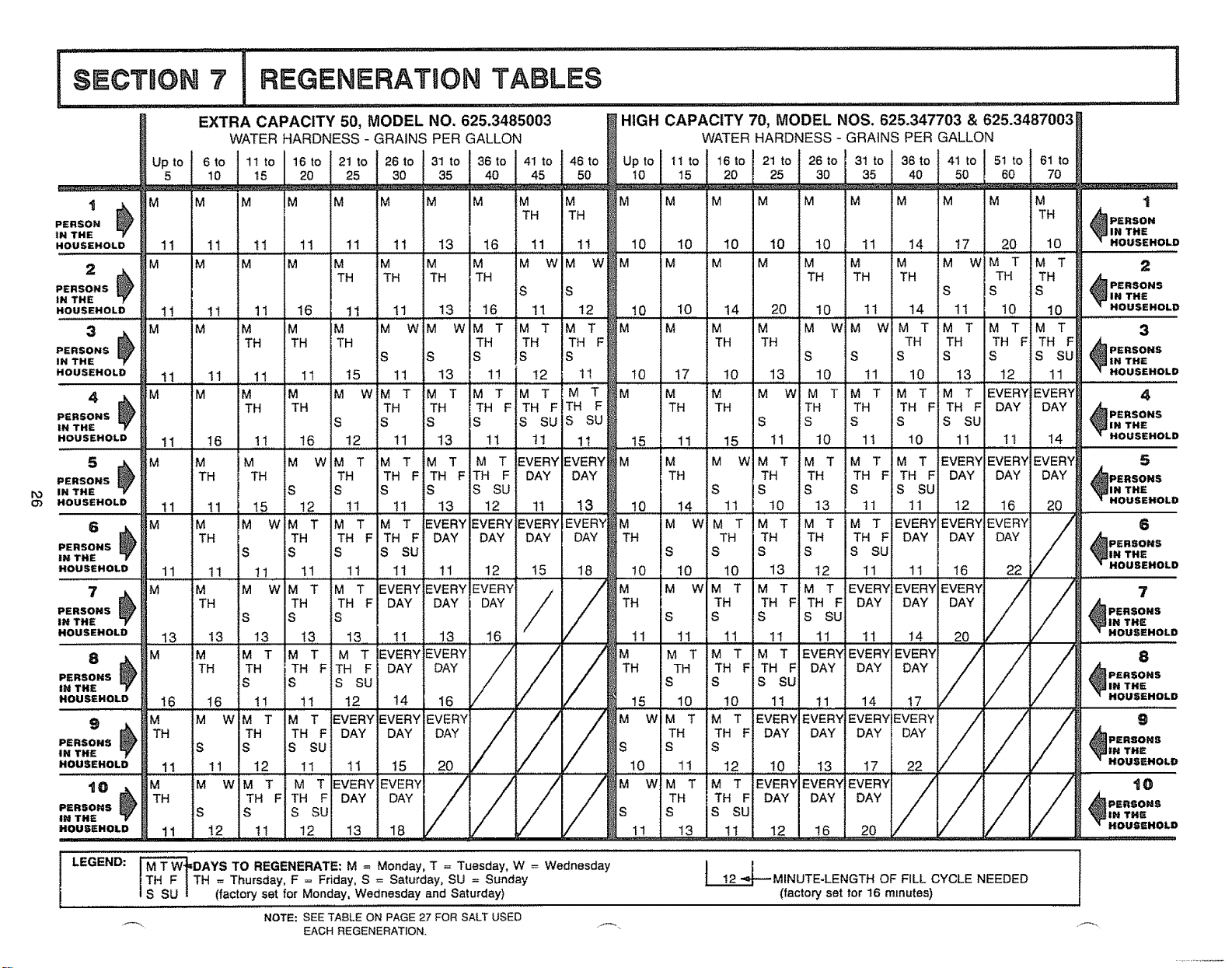
REGENERATION TABLES: The tables (page 26)
make it easy for you to pick the best regeneration
and fill time setting to use.
Step 1 -- Go down the side of the table for your
model, to the number of persons in your family, or
the number of people in the house using water,
Step 2 -- Across the top of the table, find the col-
umn listing the grains per gallon hardness of your
water.
Step 3 -- Read across and down the table fo find
the point where steps 1 and 2 meet, At this meeting
point, suggested days to regenerate, and fill cycle
minutes needed are shown,
WRITE IN YOUR RESULTS HERE°
1, M T W TH F S SU Suggested days to
-circle suggested days- regenerate
2. _Fill Cycle minutes needed
TO SET THE TIMER FOR DAYS OF REGENERA-
TION, AND FILL MINUTES, DO THE FOLLOWING.
NOTE: Remember, the timer is factory set for Mon-
day, Wednesday and Saturday regenerations star-
ting at 2:00 AM. Fill time is factory set for 16 minutes.
NOTE: Read "Automatic Bypass" page 21, when
choosing a regeneration starting time other than 2:00
AM,
b= Press the SET/CLEAR button [] until the de-
sired regeneration starting time shows in the
display°
"I. SET DAYS AND TIME OF REGENERATION,
OR RECHARGE
a. Press the RECHARGE TIME button [] once, to
display the factory set regeneration days and
starting time (flashing) To change the regenera-
tion start time, do step b following Otherwise go
to step c
NOTE: Press SET/CLEAR and quickly release to
move the display ahead 1 hour at a time. Or, hold
the SET/CLEAR button to move the display ahead
2 hours each second
C, Press the RECHARGE DAY button [] and SUn-
day begins to flash.
AM
MO WE SA
@
@
@
_. olf you want regenerations on Sunday (from regen-
eration table), press the SET/CLEAR button [] to
PRESENT TIME AND display ONo
...If you do not want Sunday regenerations, press
RECHARGE TIME SET/CLEAR button [] to display OFF
RECHARGE DAY
d. Press the RECHARGE DAY button [] again to
display a flashing MOnday and ON (factory set
continued, page 27
25
I,°,:,',,-,,,:,,,,,,!
EXTRA CAPACITY 50, MODEL NO. 625.3485003 HIGH CAPACITY 70, MODEL NOS. 625.347703 & 625.3487003
WATER HARDNESS - GRAINS PER GALLON WATER HARDNESS - GRAINS PER GALLON
t _. M M M IM M M M M M M M M M M M M M M M M .
[
TH TH TH Am
)
PERSON
ERSON
N THE _1 IN THE
IOUSEHOLD 11 11 11 1! 11 !1 13 t6 11 1! 10 10 10 10 t0 I1 14 17 20 t0 -- HOUSEHOL£
........... ,....... ,,,,,,,,,,,,,,,,.
M M M M M M M M W M W M ;M M M M M M M W M T M T 2
TH TH TH TH TH TH TH TH TH ._
PERSONS
S S S S S "_IN THE
11 11 13 16 11 12 10 I0 14 20 t0 II 14 tl 10 10 -- HOUSEHOL[
,,,i
M M W M W M T M T M T M M M M M WiM W M T M T M T M T 3
ERSONS
N THE
1t , 11 11
3 M M M
=ERSONSNTHE _ TH
4OUSEHOLD 11 11 11
4 .Jk M M M
=ERSONS _) TH
iN THE
HOUSEHOLD 11 16 1t
5 _ ;M M M
=ERSONS @ TH TH
I'O N THE
03 4OUSEHOLD 11 11 t5
6 _ IM M M
PERSONS _ TH
IN THE S
_OUSEHOLO t 1 11
7 _k M M M
;:ERSONS _ TH
LN THE
.OUSEHOLD 13 13
8 j, M M
TH
PERSONS
IN THE
HOUSEHOLD t 6 16
9 M M w
PERSONS S
IN THE
16
M
S S S SU
10 t0 11 I1 14 17
M W M T M T EVERY EVERY EVERY EVERY
TH TH F DAY DAY DAY DAY
S S S
22
TH TH TH
S S S
1I I5 11 13 11
M M W M T M T M T
TH TH TH TH F
S S S S
t6 12 11 13 1t
TH TH TH TH TH F TH F _PERSONS
S S S S S S SU _|N THE
t7 I0 13 10 I1 t0 13 12 11 HOUSEHOL_
M M M W M T M T M T M T EVERY EVERY 4
TH TH TH TH TH F TH F DAY DAY _PERSOHS
S S S S S SU _Im THE
1I 15 tl 10 1t 10 1t 11 14 --HOUSEHOL_
, ,,............ ,,, ,,
M M WIM T M T M T M T EVERY EVERY EVERY 5
TH ,_R TR TH F TH F DAY DAY DAY _PERSONS
s li_ s s s su _,N THE
14 11 10 13 1I 11 12, 16 20 --HOUSEHOL_
M W M T H T M T M T EVERY EVERY EVERY/ 6
TH TH TH F DAY DAY DAY / _PERSONS
S S S S S SU _ZN THE
! I0 10 13 12 I1 11 16 2__/ _ H°USEHOL©
M W M T M T M T EVERY EVERY EVERY 7
TH TH F TH F DAY DAY DAY
PERSONS
S S S S SU _m THE
1I 11 I1 11 11 14 20 --HOUSEHOLD
M T M T M T EVERY EVERYEVERY/// _ .
TH TH F TH F DAY DAY DAY PERSONS
"_BIH THE
'l HOUSEHOLO
TH TH F TH F DAY DAY
S S S SU
11 11 11 11 tl I2
W M T iM T EVERY!EVERY EVERY
iTH TH F
S S
t2 11 I0
iM T[M T M
ITH FITH F
S SU S SU
tl 11 15
M W M T M T iM T M T EVERY EVERY M
TH TH F TH F!TH F DAY DAY
S S S iS S SU
12 1I 11 13 12 1! 13 10
WiM T M T M T EVERYiEVERYEVERY EVERY M
DAY DAY TH
HOUSEHOLO, .. 11 . 11 . 12 . I1 . 11 15 20
,0 M M W M T M T 5VERYEVERY////
_) TH TH F TH F DAY DAY
////
PERSO.S S S S SU
IM THE
HOUSEHOLD 11 12 1t 12 13 18
t5 18 !0
!S S S
13 t3 13 11 13 16 1I
[M Z M Z M Z EVERYEVERYi/i
TH TH F TH F DAY DAY f_H
iS S S SU
!! 11 t2 !4. 16 15
M T M TF EVERYEVERY'EVER"t/i /
TH TH DAY DAY DAY
S S SU
10 11 12 10 I3 17
M W M T M T EVERY EVERY EVERY
TH TH F DAY DAY DAY
S S S SU
11 13 11 12 16 20
//7 '
_PERSONS
IN THE
-- HOUSEHOLD
////- ,o
_PERSONS
l LEGEND: _DAYS TO REGENERATE: M = Monday, T = Tuesday, W = Wednesday
1TH F ] TH = Thursday, F = Friday, S = Saturday, SU = Sunday
I S SU ! (factory set for Monday, Wednesday and Saturday)
_MINUTE-LENGTH OF FILL CYCLE NEEDED
(factory set tar 16 minutes)
NOTE: SEE TABLE ON PAGE 27 FOR SALT USED
f'-" EACH REGENERATION. ""--"
rllr i7 t OTHER THnNGS TO KNOW
n,
continued from page 25
recharge). As you did in step c, use the SET/
CLEAR button [] to change the display from ON
to OFF, or from OFF to ON
e. Press RECHARGE DAY button [] to display a
flashing TUesday, WEdnesday, etc., each time
using the SET/CLEAR button [] to display either
ON or OFF as needed,
After recharge is either set or cancelled for
SAturday, press the PRESENT TIME AND DAY
button [] once again to return the present time
and day display_
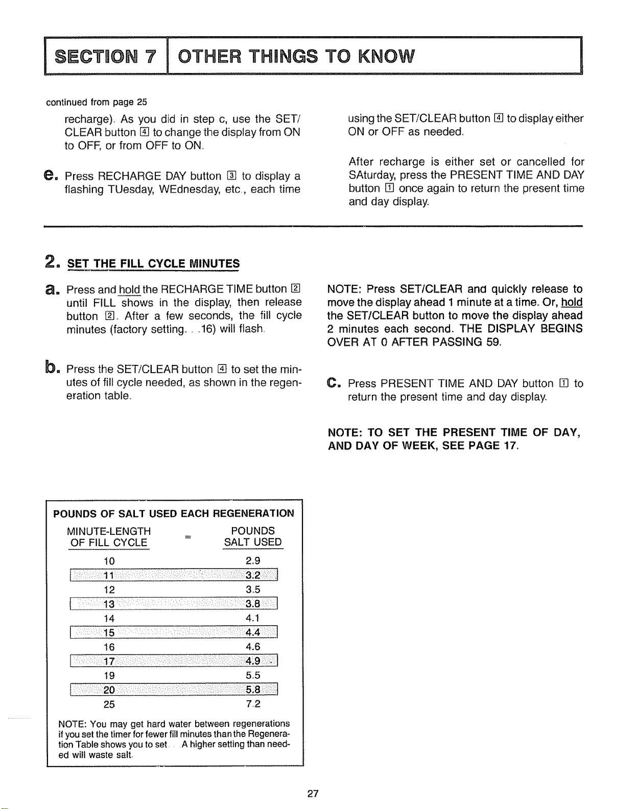
2. SET THE FILL CYCLE MINUTES
a. Press and hold the RECHARGE TIME button []
until FILL shows in the display, then release
button []_ After a few seconds, the fill cycle
minutes (factory setting ..... 16) wilt flash,
b= Press the SET/CLEAR button [] to set the min-
utes of fill cycle needed, as shown in the regen-
eration table.,
NOTE: Press SET/CLEAR and quickly release to
move the display ahead 1 minute at a time. Or, hold
the SET/CLEAR button to move the display ahead
2 minutes each second. THE DISPLAY BEGINS
OVER AT 0 AFTER PASSING 59.
C. Press PRESENT TIME AND DAY button [] to
return the present time and day display°
NOTE: TO SET THE PRESENT TIME OF DAY,
AND DAY OF WEEK, SEE PAGE 17o
POUNDS OF SALT USED EACH REGENERATION
MINUTE-LENGTH
OF FILL CYCLE
POUNDS
SALT USED
10 2°9
12 3,,5
14 4.I
16 4.6
19 5,,5
25 7.,2
NOTE: You may get hard water between regenerations
ifyou set the timer for fewer fill minutes than the Regenera-
tion Table shows you to set.. A higher setting than need-
ed will waste salt,
27
A B
FF<
Dia.
Resin Tank
MODEL AND
RATING DECAL
(under cover)
J/Inlet-Outlet
±
1 ,
_rj
-I-
H
c
oo
rr
DiMENSiONS
Dimension
A
B
C
D
E*
G
H
"from center of inlet to center of outlet
HIGH
EX, CAPACITY 70
CAPACITY 50 MODEL NOSe
MODEL NO. 625.347703
625°3485003 & 625°3487003
in, cm. in, cm.
421/2 108 471/2 1t9,7
361/2 927 411/z 1054
171/2 44,5 17t/2 445
123/4 32 4 123/4 32 4
3 3f8 86 3 3/8 8 6
8 2&3 8 20,3
35 889 40 101,6
361/2 927 411/2 105 4
SPECiFiCATIONS
SOFTENER RATED CAPACITY (Grains)
@ Pounds of Salt
SERVICE FLOW RATE (Gallons Per Minute)
not over 15 pounds per square inch (psi)
pressure loss
REGENERATION FLOW RATES
FILL (Gat, Per Mira Flow to Storage Tank)
BRINING
BRINE RINSE _. (Gallon Per' Minute
BACKWASH ._ Flow to Drain)
FAST RINSE
TYPE OF ION EXCHANGE MATERIAL
(RESIN)
AMOUNT OF RESIN (Cubic Feet)
TYPE OF SALT NEEDED
ALTERNATE TYPE OF SALT
MAXIMUM WATER HARDNESS (Grains
Per Gallon)
MAXIMUM "CLEAR WATER" IRON
(Parts Per Million)
NOTE:The aboveflow ratesobtainedteeUngat 35 psi Inletpressure.
MODEL NO.
625.3485003
18,600 @ 55 (25 Kg)
16,600 @ 4.5 (2,,0 Kg)
13,900 @ &3 (15 Kg)
8.0 (30.3 Liters)
,1 (,4 liters)
.16 (6 liters)
.11 (.,4 liters)
1.8 (6.8 liters)
1 8 (6.8 liters)
MODEL NOS.
625.3487003/625.347703
23,500 @ 7_0 (&2 Kg)
20,500 @ 54 (2.5 Kg)
16,500 @ 38 (1,7 Kg)
14,000 @ 2.8 (1.4 Kg)
&0 (30.3 Liters)
.1 (,,4 liters)
,,16 (,6 liters)
11 (.4 liters)
18 (6,8 liters)
18 (6.8 liters)
High Capacity Resin
.60 (o017 cu. m) .75 (_022 cu. m)
Nugget or Pellet
Pure, evaporated, compacted water softener salt
50 70
2_0
3_0
28
OTHER THBNGS TO
KNOW
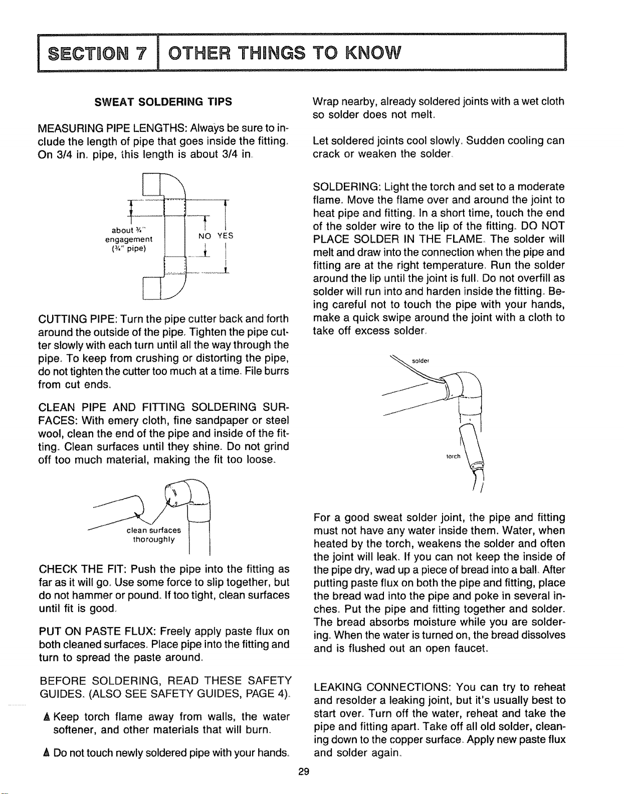
SWEAT SOLDERING TIPS
MEASURING PIPE LENGTHS: Always be sure to in-
clude the length of pipe that goes inside the fitting°
On 314 in_ pipe, this length is about 3/4 in.
about 3/,-
engagement
(3/,- pipe)
CUTTING PIPE: Turn the pipe cutter back and forth
around the outside of the pipe. Tighten the pipe cut-
ter slowly with each turn until all the way through the
pipe° To keep from crushing or distorting the pipe,
do not tighten the cutter too much at a time° File burrs
from cut ends,_
CLEAN PIPE AND FITTING SOLDERING SUR-
FACES: With emery cloth, fine sandpaper or steel
wool, clean the end of the pipe and inside of the fit-
ting. Clean surfaces until they shine. Do not grind
off too much material, making the fit too loose.
Wrap nearby, already soldered joints with a wet cloth
so solder does not melt.
Let soldered joints cool slowly. Sudden cooling can
crack or weaken the solder
SOLDERING: Light the torch and set to a moderate
flamen Move the flame over and around the joint to
heat pipe and fitting° In a short time, touch the end
of the solder wire to the lip of the fitting° DO NOT
PLACE SOLDER IN THE FLAME° The solder will
melt and draw into the connection when the pipe and
fitting are at the right temperature. Run the solder
around the lip until the joint is full. Do not overfill as
solder will run into and harden inside the fitting. Be-
ing careful not to touch the pipe with your hands,
make a quick swipe around the joint with a cloth to
take off excess solder.
clean s[jrfaces
thoroughly
CHECK THE FIT: Push the pipe into the fitting as
far as it wilt go_ Use some force to slip together, but
do not hammer or pound,. If too tight, clean surfaces
until fit is good,
PUT ON PASTE FLUX: Freely apply paste flux on
both cleaned surfaces. Place pipe into the fitting and
turn to spread the paste around_
BEFORE SOLDERING, READ THESE SAFETY
GUIDES. (ALSO SEE SAFETY GUIDES, PAGE 4).
A Keep torch flame away from walls, the water
softener, and other materials that will burn_
& Do not touch newly soldered pipe with your hands_
29
For a good sweat solder joint, the pipe and fitting
must not have any water inside them. Water, when
heated by the torch, weakens the solder and often
the joint wi!l leak. If you can not keep the inside of
the pipe dry, wad up a piece of bread into a ball. After
putting paste flux on both the pipe and fitting, place
the bread wad into the pipe and poke in several in-
cheso Put the pipe and fitting together and solder.
The bread absorbs moisture while you are solder-
ing_When the water isturned on, the bread dissolves
and is flushed out an open faucet.
LEAKING CONNECTIONS: You can try to reheat
and resolder a leaking joint, but it's usually best to
start over_ Turn off the water, reheat and take the
pipe and fitting apart. Take off all old solder, clean-
ing down to the copper surface. Apply new paste flux
and solder again,.
!ooo,,o.,no'.o. ................
WSRING SCHEIVIATaC
t
BOTTOM (POSITION) [
SWITCH ...._-_.... _,_
• t. _
BACK OF
FACE PLATETIMER
wh,
grn,
I
I
I
J
TRANSFORMER
PowER'2°v--"L---1
_ i g
souacE_1_
24V
3O

31
31
ASSEMBLY
35
26
t_
22
2i
/ 20
/
3
4
6
VALVE
page 34)
10
11
_12
3
14
"t5
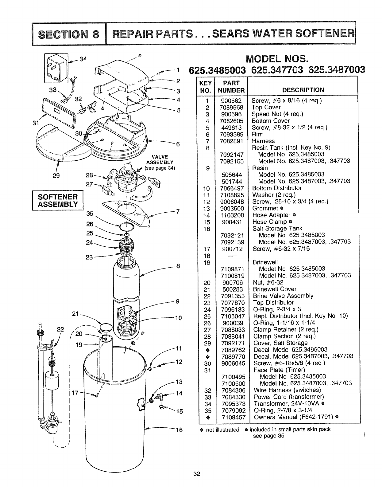
MODEL NOS.
625.3485003
KEY PART
NO. NUMBER
1 900562
2 7089568
3 900596
4 7082605
5 449613
6 7093389
7 7082891
8
7092147
7092155
9
505644
501744
t0 7066497
11 7108825
12 9006048
13 9003500
14 1103200
15 900431
16
7092121
7O92139
17 900712
18
19
20
21
22
23
24
25
26
27
28
29
3O
31
7100495
7100500
32 7084306
33 7084330
34 7095373
i 35 7079O92
_ 7109457
notillustrated
625.347703 625.3487003
7109871
7100819
900706
500283
7091353
7077870
7096183
7105O47
900039
7088033
7088041
7092171
7089762
7089770
9006045
DESCRIPTION
Screw, #6 x 9/16 (4 req..)
Top Cover
Speed Nut (4 req..)
Bottom Cover
Screw, #8-32 x 1/2 (4 req)
Rim
Harness
Resin Tank (Incl. Key No..9)
Model No 625,3485003
Model No, 625.3487003, 347703
Resin
Model No. 625.3485003
Model No_ 6253487003, .347703
Bottom Distributor
Washer (2 req.)
Screw, 25-10 x 3/4 (4 req.)
Grommet •
Hose Adapter •
Hose Clamp e
Salt Storage Tank
Model No 6253485003
Model No. 6253487003, .347703
Screw, #6-32 x 7/16
Brinewell
Model No 625.3485003
Model No. 6253487003, 347703
Nut, #6-32
Brinewell Cover
Brine Valve Assembly
Top Distributor
O-Ring, 2-3/4 x 3
RepL Distributor (lncL Key No 10)
O-Ring, 1-1/16 x 1-1/4
Clamp Retainer (2 req.)
Clamp Section (2 req.)
Cover, Salt Storage
Decal, Model 62&3485003
Decal, Model 625.3487003, .347703
Screw, #6-18x5/8 (4 req)
Face Plate (Timer)
Model No 625°3485003
Model No. 6253487003, 347703
Wire Harness (switches)
Power Cord (transformer)
Transformer, 24V-t0VA ®
O-Ring, 2-7/8 x 3-1/4
Owners Manual (F642-179t) •
® _ncluded in small parts skin pack
- see page 35
32
i
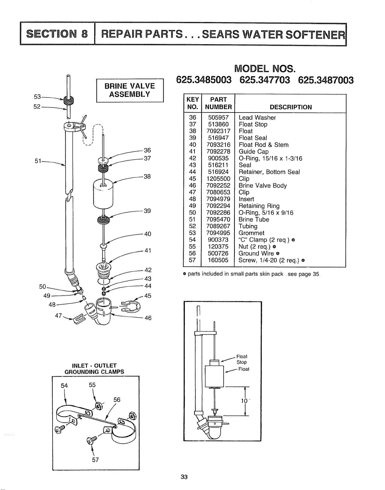
SECTUON 8
BRINE VALVE
ASSEMBLY
51
49
48
INLET - OUTLET
GROUNDING CLAMPS
54 55
57
MODEL NOS.
625.3485003 625.347703 625.3487003
KEY
NO.
36 505957
37 513860
38 7092317
39 516947
40 7093216
41 7092278
42 900535
43 516211
44 516924
45 1205500
46 7092252
47 7080653
48 7094979
49 7092294
50 7092286
51 7095470
52 7089267
53 7094995
54 900373
55 120375
56 500726
57 160505
PART
NUMBER DESCRIPTION
Lead Washer
Float Stop
Float
Float Seal
Float Rod & Stem
Guide Cap
O-Ring, 15/16 x 1-3/16
Seal
Retainer, Bottom Seal
Clip
Brine Valve Body
Clip
Insert
Retaining Ring
O-Ring, 5/16 x 9/t6
Brine Tube
Tubing
Grommet
"C" Clamp (2 req,) ®
Nut (2 req,) e
Ground Wire e
Screw, 1/4-20 (2 req,) e
e parts included in small parts skin pack see page 35
.,.........._Float
Stop
Float
T
10"
33
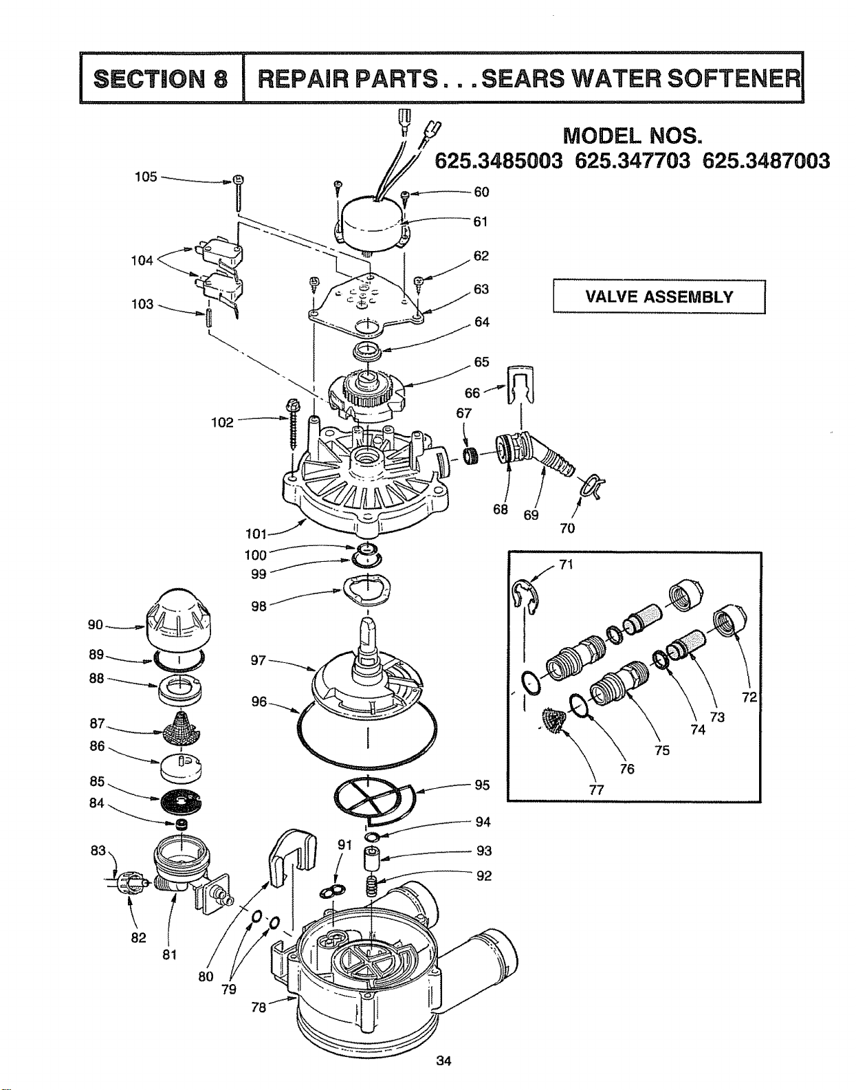
I-,,.°oT.o.8
61
104
" 62
63
VALVE ASSEMBLY
102
t
68 69
70
71
77
76
73
74
75
82
8i
80
79
92
34
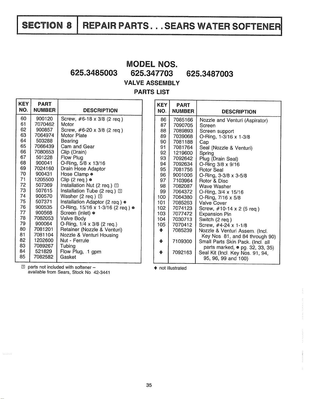
625.3485003
MODEL NOS.
625.347703
VALVE ASSEMBLY
PARTS LIST
625.3487003
KEY t
NO:I
60
61
62
63
64
65
66
67
68
69
70
71
72
73
74 ,
77
78
79
8O
81 1
82
83
84
85 _
PART
NUMBER DESCRIPTION
900120
7070462
900857
7064974
503288
7066439
7080653
501228
900041
7024160
900431
1205500
507369
507615
900570
507371
900535
900568
7O82053
900064
7081201
7081104
1202600
7089267
521829
7082582
Screw, #6-18 x 3/8 (2 req)
Motor
Screw, #6-20 x 3/8 (2 req.)
Motor Plate
Bearing
Cam and Gear
Clip (Drain)
Flow Plug
O-Ring, 5/8 x 13/16
Drain Hose Adaptor
Hose Clamp ®
Clip (2 req.) e
Installation Nut (2 req) []
Installation Tube (2 req..) []
Washer (2 req) []
Installation Adaptor (2 req.) e
O-Ring, I5/16 x 1-3/16 (2 req.) e
Screen (inlet) e
Valve Body
O-Ring, 1/4 x 3/8 (2 req.)
Retainer (Nozzle & Venturi)
Nozzle & Venturi Housing
Nut - Ferrule
Tubing
Flow Plug, 1 gpm
Gasket
m parts not included with softener -
available from Sears, Stock No 42_3441
KEY PART
NO_ NUMBER
86 7085166
87 7090705
88 7089893
89 7039068
90 7081188
91 7081764
92 1219600
93 7092642
94 7092634
95 7081756
96 9001006
97 7103964
98 7082087
99 7064372
100 7064380
t01 7085263
102 7074123
!03 7077472
t04 7030713
105 7070412
7085239
7109300
7092163
DESCRIPTION
Nozzle and Venturi (Aspirator)
Screen
Screen support
O-Ring, 1-3/16 x 1-3/8
Cap
Seal (Nozzle & Venturi)
Spring
Plug (Drain Seal)
O-Ring 3/8 x 9/16
Rotor Seal
O-Ring, 3-3/8 x 3-5/8
Rotor & Disc
Wave Washer
O-Ring, 3/4 x 15/16
O-Ring, 7/16 x 5/8
Valve Cover
Screw, #10-14 x 2 (5 req)
Expansion Pin
Switch (2 req)
Screw, #4-24 x 1-1/8
Nozzle & Venturi Assemo (Incl..
Key Nos 81, and 84 through 90)
Small Parts Skin Pack_.(Inc!. all
parts marked, e pg. 32, 33, 35)
Seal Kit (Incl. Key Nos.. 91, 94,
95, 96, 99 and 100)
not illustrated
35
OWNERS
MANUAL
SERVICE
MODEL NOS.
625°3485003
EXTRA CAPACITY' 50
625.347703
625.3487003
HIGH CAPACITY 70
HOW TO ORDER
REPAIR PARTS
TELL SEARS YOU
WANT IT INSTALLED
THEN RELAX
F642-t 79t
Now that you have purchased your-water softener, should a need ever
exist for repair parts or service, simply contact any Sears Service Center..
Be sure to provide all pertinent facts when you call or visit.
The model number of your water softener is found on the rating decal_
This decal is on the storage tank rim, under the cover plate
WHEN ORDERING REPAIR PARTS, ALWAYS GIVE THE FOLLOW-
ING INFORMATION:
- PART NUMBER
- MODEL NUMBER
- PART DESCRIPTION
-NAME OF ITEM
All parts listed may be ordered from any Sears Service Center,
tf the parts you need are not stocked tocally, your order will be elec-
tronically transmitted to a Sears Repair Parts Distribution center for
handling.
When Sears arranges the installation, you can be sure the job is done
right. We will arrange for professional workmanship .... and we'll take care
of the entire project° What's more, during installation you get insured
protection _.,., against_property damage and also against accidents to
workmen, All you have to do is talk to your Sears salesperson or call your
nearest Sears store today for detailed information,.
Sears, Roebuck and Co., Chicago, Ill. 60684. U.S.Ao
7I 09457 (6/91)