1.0 METER FUNCTIONS
2.0 Read First: Important Safety Information
Read this operators manual thoroughly before using this tester. This manual is
intended to provide basic information regarding this tester and to describe
common test procedures which can be made with this unit. Many types of appliance,
machinery and other electrical circuit measurements are not addressed in this manual and
should be handled by experienced service technicians.
Use extreme caution when using this tester. Improper use of this tester
can result in severe damage to property, severe personal injury or death.
Follow all instructions and suggestions in this operators manual as well as observing
normal electrical safety precautions. Do not use this tester if you are unfamiliar with
electrical circuits and proper test procedures.
SAFETY WARNINGS
This instrument has been designed, manufactured and tested according to IEC61010: Safety
requirements for Electronic Measuring apparatus, and delivered in the best condition after
passing inspection. This instruction manual contains warnings and safety rules which must
be observed by the user to ensure safe operation of the instrument and retain it in safe
condition. Therefore, read through these operating instructions before using the instrument.
• Read through and understand the instructions contained in this manual before using the
instrument.
Keep the manual at hand to enable quick reference whenever necessary.
• The instrument is to be used only in its intended applications.
• Understand and follow all the safety instructions contained in the manual.
• It is essential that the above instructions are adhered to.
• Failure to follow the above instructions may cause injury, instrument damage and/or
damage to equipment under test.
is reserved for conditions and actions that can cause serious or fatal
injury.
is reserved for conditions and actions that can cause injury or
instrument damage.
Never make measurement on a circuit in which voltage over AC 600 V exists.
• Do not attempt to make measurement in the presence of flammable gasses. Otherwise, the
use of the instrument may cause sparking, which can lead to an explosion.
Never attempt to use the instrument if its surface or your hand is wet.
• Do not exceed the maximum allowable input of any measuring range.
• Never open the battery cover during a measurement.
• The instrument is to be used only in its intended applications or conditions. Otherwise,
safety functions equipped with the instrument don’t work, and instrument damage or
serious personal injury may be caused.
• Never attempt to make measurement if any abnormal conditions, such as broken case and
exposed metal parts are found on the instrument.
• Do not install substitute parts or make any modification to the instrument. For repair or
re-calibration, return the instrument to your local distributor from where it was purchased.
• Verify proper operation on a known source before use or taking action as a result of the
indication of the instrument.
Use appropriate personal protective equipment such as insulating gloves,
insulating boots, and safety glasses.
• Set the function switch to an appropriate position before starting measurement.
• Do not expose the instrument to the direct sun, high temperature and humidity or dewfall.
• Altitude 2000m or less. Appropriate operating temperature is within 0 °C and 32 °C.
• This instrument isn’t dust and water proofed. Keep away from dust and water.
• When the instrument will not be in use for a long period, place it in storage after removing the battery.
• Cleaning: Use a cloth dipped in water or neutral detergent for cleaning the instrument. Do not
use abrasives or solvents otherwise instrument may get damaged, deformed or discolored.
3.0 SPECIFICATIONS
• Stud detection depth and accuracy: 3/4"
+
⁄
-
1/8".
• Pipe detection depth: 2-1/2" through 1/2" drywall.
• AC volt detection distance/depth: 3-1/2" through 1/2" drywall.
• Operating Range: Non-contact AC Detector: 50-600 V AC 60 Hz; Plug in receptacle tester:
120 V AC 60 Hz
• Indicators: Audible and Visual
• Operating environment: 32 - 104 °F (0 - 32 °C) 80% RH max., 50% RH above 30 °C
Altitude up to 2000 meters.
Indoor use. Pollution degree 2. Accordance with IED-664.
• Battery: operates from one 9 Volt.
• Cleaning: Remove grease and grime with clean, dry cloth.
Marks listed below are used on this instrument.
User must refer to the manual.
Instrument with double or reinforced insulation.
Indicates that this instrument can touch bare conductors when measuring a voltage
corresponding to the applicable measurement, which is marked next to this symbol.
4.0 Operation
Combines all the functions necessary to accurately and
safely install 3 wire outlets, wall switches and lighting
fixtures in 4 easy steps. Detects wood or metal studs,
metal pipes and AC voltage hidden behind walls. Includes
a 3-wire outlet tester with GFCI test function to verify the
outlet has been wired properly.
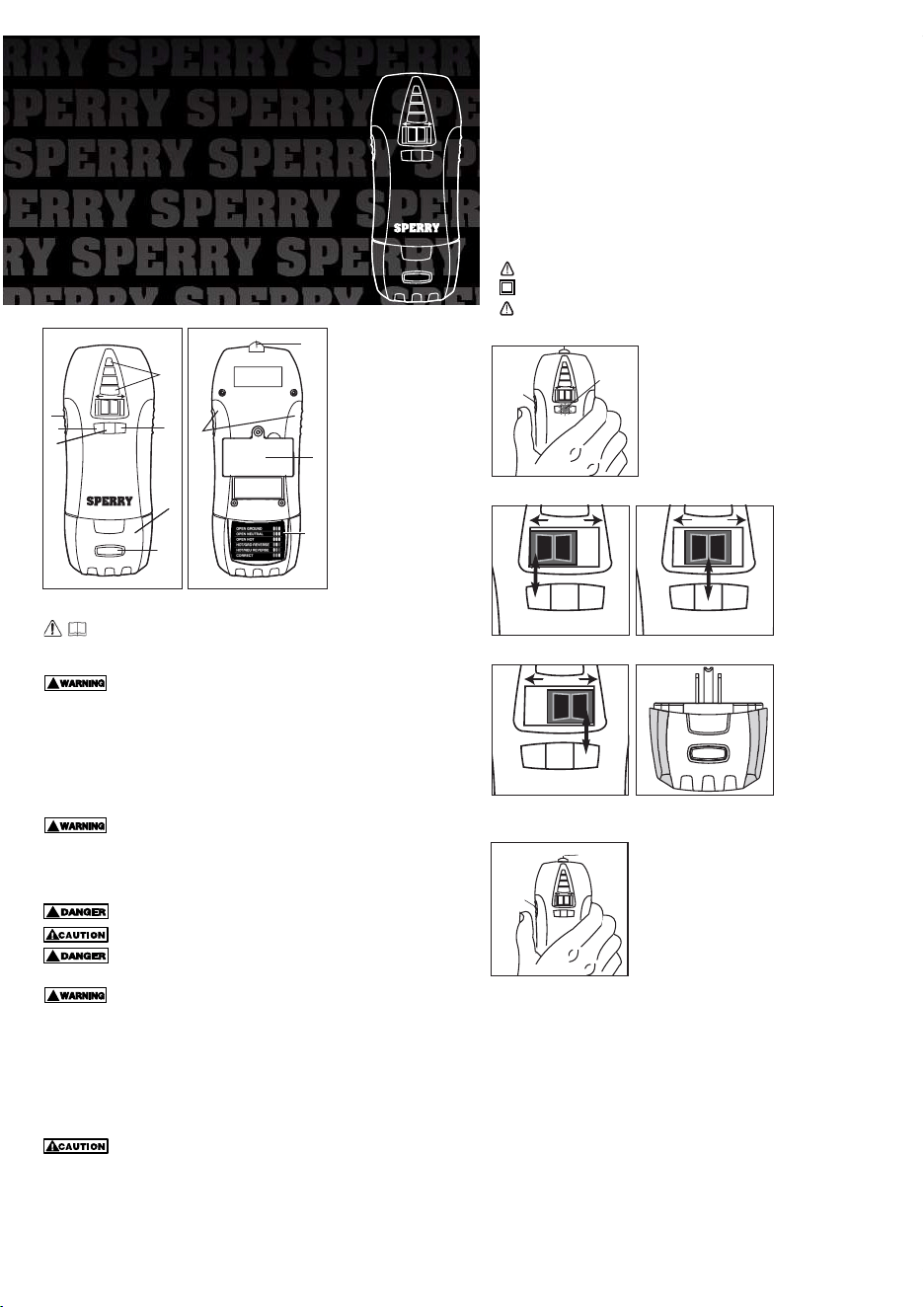
NOTE: Low battery indicator: Before using, test the unit
for good batteries. Press and hold the “scan/calibration”
button on the side. If the batteries are low the middle “LED”
by the “metal” detection will flash. If low, replace with fresh
batteries. (Fig. 1)
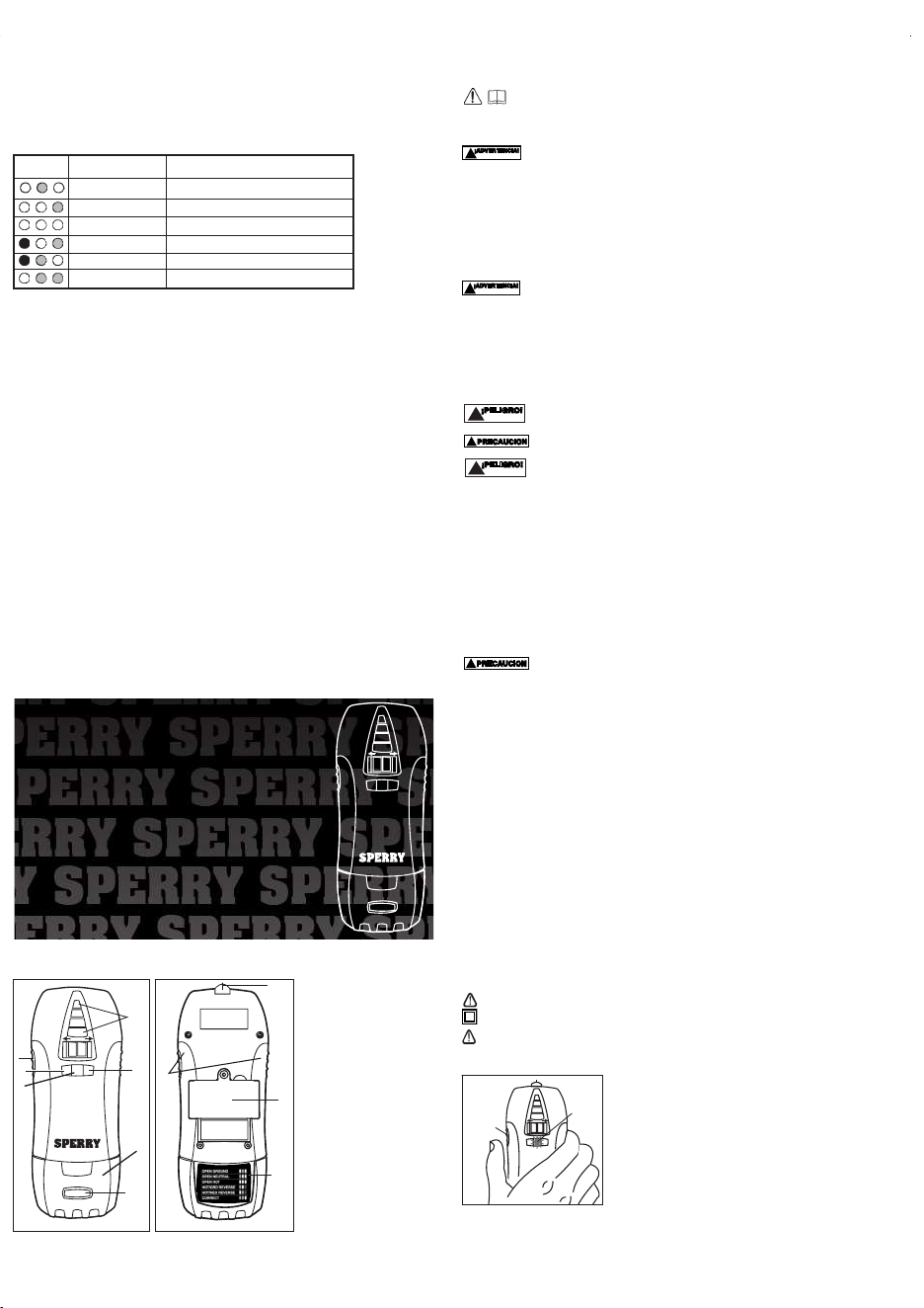
STEP 1: Place the switch in
the “Stud” position (Fig. 2)
and scan the surface for
wood and metal studs. Mark
these locations with the
metal marking tip built into
the top of the tester.
STEP 2: Move the switch to
the “Metal” setting (Fig. 3)
and scan the surface for any
hidden metal pipes that
could interfere with the
installation.
STEP 3: Move the switch to
the “AC Volt” setting (Fig. 4)
and scan the surface a third
time to detect any live wires
behind the wall. Mark the
position of these wires if
they’re in proximity to the l-
ocation of the electrical box,
switch or fixture to be
installed.
STEP 4: After installation of
the new outlet, switch or
fixture, test the wiring with
the attached outlet tester
(Fig. 5) or non-contact AC
Volt sensing tip.
4.1 Stud detection (wood and metal)
a. Position the select switch in the “Stud” position. (Fig. 2)
b. Place the unit flat against the surface to be scanned. (Fig.
6)
c. Press the calibrate/activate button located on the side to
calibrate the unit.
Continue to press and hold this button while sliding the
unit across the surface.
d. As the unit approaches a stud edge the LEDs will start to
illuminate, until they reach the top. This indicates the stud
edge.
e. Mark the stud edge with the metal marking tip built into
the top of the tester.
f. To find the middle of the stud, scan again from the
opposite direction and mark the stud edge. The center
between the two marked points is the center of the stud.
4.2 Metal Pipe detection
a. Position the “select” switch in the “Metal” position. (Fig. 3)
b. Place the unit flat against the surface to be scanned.
c. Press the calibrate/activate button located on the side to activate the test. Continue to
press and hold this button while sliding the unit across the surface. (Fig. 6)
d. As the unit approaches a metal pipe the LEDs will start to illuminate, until they reach the
top. This indicates the location of the metal pipe.
e. Mark this location with the metal marking tip built into the top ofthe tester.
4.3 AC Voltage Detection
a. Position the select switch in the “AC Volt” position. (Fig. 4)
b. Place the unit flat against the surface or position the nose close to the surface to be scanned.
c. Press the calibrate/activate button located on the side to activate the test. Continue to
press and hold this button while sliding the unit across the surface. (Fig. 6)
d. As the unit approaches a “live” 50 V AC or higher source, such as a wire, the unit will give
off both an audible and visual signal indicating the presence of AC voltage.
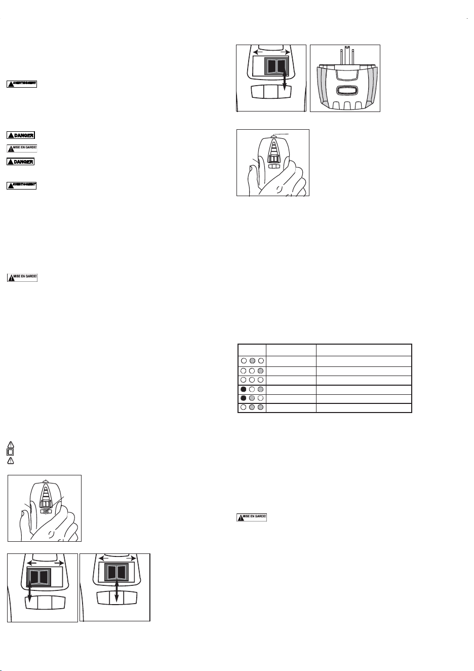
4.4 Receptacle tester
1. Detach the receptacle tester from the scanner housing.
2. Plug the tester into any 120 Volt standard or GFCI outlet.
3. View the indicators on the tester and match with the chart on the tester. (Fig. 7)
4. If the tester indicates a wiring problem then turn off all power to the outlet and repair
wiring. (Consult an electrician if necessary)
5. Restore power to the outlet and repeat steps 1-3.
To test GFCI Protected Outlets:
1. Consult the GFCI manufacturer’s installation instructions to determine that the GFCI is
installed in accordance with the manufacturer’s specifications.
2. Check for correct wiring of receptacle and all remotely connected receptacles on the
branch circuit.
3. Operate the test button on the GFCI installed in the circuit. The GFCI must trip. If it
doesn’t, do not use the circuit and consult an electrician. If the GFCI does trip, reset the
GFCI. Then, insert the GFCI tester into the receptacle to be tested.
4. Activate the test button on the GFCI tester for a minimum of 6 seconds when testing the
GFCI condition. Visible indication on the GFCI tester must cease when tripped.
5. If the tester fails to trip the GFCI, it suggests:
a.) a wiring problem with a totally operable GFCI, or
b.) proper wiring with a faulty GFCI. Consult with an electrician to check the condition of
the wiring and GFCI.
When testing GFCIs installed in 2- wire systems (no ground wire available), the tester may
give a false indication that the GFCI is not functioning properly. If this occurs, recheck the
operation of the GFCI using the test and reset buttons.The GFCI button test function will
demonstrate proper operation.
NOTE:
1. All appliances or equipment on the circuit being tested should be unplugged to help avoid
erroneous readings.
2. Not a comprehensive diagnostic instrument but a simple instrument to detect nearly all
probable common improper wiring conditions.
3. Refer all indicated problems to a qualified electrician.
4. Will not indicate quality of ground.
5. Will not detect two hot wires in a circuit.
6. Will not detect a combination of defects.
7. Will not indicate a reversal of grounded and grounding conductors.
5.0 Replacing the batteries.
This unit operates from a standard 9 Volt battery. To replace, remove the battery door cover,
located on the back, with a small screwdriver. Replace with new battery and then shut the
battery door and replace screw. (Refer to 1.0, Meter Functions)
1.0
FUNCIONES DEL MEDIDOR
2.0 Leer primero: Informació n de seguridad importante
Lea completamente este manual del operador antes de usar este medidor. Este
manual está destinado a dar informació n bá sica referente a este medidor y
describir procedimientos de prueba comunes que se pueden realizar con esta unidad.
Muchos tipos de mediciones de artefactos, maquinaria y otros circuitos elé ctricos no se
tratan en este manual y deben realizarlas los té cnicos de servicio experimentados.
Sea precavido al utilizar este medidor. El uso indebido de este medidor
puede causar dañ os materiales severos y lesiones físicas graves o fatales.
Siga todas las instrucciones y sugerencias en este manual del operador y tambié n
observe las precauciones normales de seguridad elé ctrica. No use este medidor si no
está familiarizado con circuitos elé ctricos y los procedimientos de prueba apropiados.
ADVERTENCIAS DE SEGURIDAD
Este instrumento ha sido diseñ ado, fabricado y probado conforme a IEC61010: Requisitos
de seguridad para aparatos electró nicos de medició n, y se entrega en el mejor estado
despué s de pasar la inspecció n. Este manual de instrucciones contiene advertencias y
reglas de seguridad que el usuario debe observar para garantizar el funcionamiento seguro
del instrumento y mantener su buen estado sin presentar peligro. Por lo tanto, lea estas
instrucciones operativas antes de usar el instrumento.
• Lea totalmente y en detalle las instrucciones contenidas en este manual antes
de usar el instrumento.
• Conserve a mano el manual para poder usarlo a modo de referencia rá pida siempre que
sea necesario.
• El instrumento debe usarse solamente en las aplicaciones contempladas.
• Siga minuciosamente todas las instrucciones de seguridad contenidas en el manual.
• Es esencial que se respeten las instrucciones anteriores.
• Si no se siguen las instrucciones anteriores puede causar lesiones, dañ o al instrumento
y/o dañ o al equipo a prueba.
se reserva para condiciones y acciones que pueden causar lesiones
serias o fatales.
se reserva para condiciones y acciones que pueden causar lesiones o
dañ os al instrumento.
• Nunca tome medidas en un circuito donde exista voltaje sobre 600 V de CA.
• No intente tomar medidas en la presencia de gases inflamables.De lo contrario, el uso del
instrumento puede causar chispas, lo cual puede ocasionar una explosió n.
• Nunca intente usar el instrumento si está mojada la superficie o la mano.
• No supere la entrada má xima permisible de cualquier rango de medició n.
• Nunca abra la tapa de la batería durante una medició n.
• El instrumento debe usarse solamente en las aplicaciones o condiciones contempladas.
De lo contrario, las funciones de seguridad con las cuales se ha equipado el instrumento
quedan inoperantes, y puede causarse dañ o al instrumento o lesiones físicas serias.
• Nunca intente tomar medidas si se encuentra alguna condició n anormal, como con la caja
rota o piezas metá licas expuestas en el instrumento.
• No sustituya piezas ni haga modificaciones al instrumento. Para reparar o recalibrar el
instrumento, devué lvalo a su distribuidor local donde lo compró .
• Verifique el funcionamiento correcto en una fuente conocida antes de usar o de actuar
basá ndose en lo que indicó el instrumento.
• Use el equipo protector personal adecuado como guantes aisladores,
botas aisladoras y anteojos de seguridad.
• Ponga el interruptor de funció n en una posició n adecuada antes de comenzar a medir.
• Inserte firmemente los conductores de prueba.
• No exponga el instrumento al sol directo, a alta temperatura ni humedad o caída de rocío.
• Altitud de 2000 m o menor. La temperatura operativa adecuada está entre 0°C y 40°C.
• Este instrumento no es a prueba de polvo ni agua. Manté ngalo alejado del polvo y del agua.
• Confirme que se haya apagado el instrumento despué s del uso. Cuando el instrumento no
vaya a estar en uso por un tiempo largo, pó ngalo en almacenamiento despué s de extraerle
las baterías.
• Limpieza: Use un pañ o sumergido en agua o detergente neutro para limpiar el
instrumento. No use abrasivos ni solventes, de lo contrario el instrumento puede dañ arse,
deformarse o decolorarse.
Secció n 3.0 Especificaciones
• Profundidad y precisió n de la detecció n de espigas: 19 mm +/- 3.2 mm.
• Profundidad de detecció n de tubería: 64 mm a travé s de panel de yeso de 13 mm.
• Profundidad o distancia de detecció n de voltaje de CA: 89 mm a travé s de panel de yeso
de 13 mm.
• Rango operativo:
Detecció n de voltaje CA sin contacto 50-600 VCA, 60 Hz;
CAT III 600V
Receptá culo del probador enchufado: 120 VCA 60 Hz
• Indicadores: Sonoros y visuales
• Ambiente operativo: 0 -32 °C 80% humedad relativa má x., 50% humedad relativa sobre los
30 °C Altitud hasta 2000 metros. Uso en interiores. Grado de contaminació n 2.
Conformidad con IED-664.
• Batería: opera con una batería de 9 voltios.
• Limpieza: Retire la grasa y la mugre con un pañ o seco y limpio.
Se usan las marcas indicadas en la tabla a continuació n en este instrumento.
El usuario debe consultar el manual.
Instrumento con aislamiento doble o reforzado.
Indica que este instrumento puede tocar conductores desnudos al medir un voltaje
correspondiente a la medició n aplicable, la cual está marcada junto a este símbolo.
4.0 Funcionamiento
Combina en 4 pasos fá ciles todas las funciones necesarias
para instalar en forma precisa y segura receptá culos de 3
conductores, tomacorrientes y lá mparas o luminarias.
Detecta espigas de madera o metal, tuberías de metal y
voltaje de CA ocultas detrá s de las paredes. Incluye un
probador de receptá culo de 3 conductores con funció n de
prueba GFCI para verificar que el tomacorriente tiene el
cableado correcto.
NOTA:
Indicador de batería baja: Antes de usar, confirme que la
unidad tenga buenas baterías. Presione y mantenga así el
botó n “escanear/calibració n” en el lado. Si las baterías está n
bajas destellará la luz indicadora central junto a la detecció n
de “metal”. Si está n bajas, reemplá celas por baterías
frescas. (Fig. 1)
Scan-Test
™
5-in-1 Scanner and Tester
• Read this owners manual thoroughly
before use and save.
P
r
e
s
s
f
o
r
G
F
C
I
T
e
s
t
S
c
a
n
-
T
e
s
t
™
5-in-1 Scanner and Tester
STUD METAL AC VOLT
P
r
e
s
s
t
o
S
c
a
n
Select
PD6902
SPERRY
INSTRUMENTS
Milwaukee,WI 53209 USA
Phone: 1-800-645-5398
www.sperryinstruments.com
P
r
e
s
s
f
o
r
G
F
C
I
T
e
s
t
S
c
a
n
-
T
e
s
t
™
5-in-1 Scanner and Tes ter
STU D METAL AC VOLT
P
r
e
s
s
t
o
S
c
a
n
Select
1
2
7
3
10
6
4
!
!
STUD METAL AC VOLT
P
r
e
s
s
t
o
S
c
a
n
Select
Calibrate
Button
Visual
Indicator
Fig. 1
Fig. 6
S
STUD METAL AC VOLT
P
r
e
s
s
t
o
S
c
a
n
Select
Calibrate
Button
Metal
Marking Tip
Fig. 7
Indicator Fault Reason for Wiring Fault
Ground contact not connected
Neutral contact not connected
Hot and ground contacts interchanged
Hot and neutral contacts interchanged
Receptacle is wired correctly
Open Ground
Open Neutral
Open Hot
Hot/Ground/Reverse
Hot/Neutral/Reverse
Correct
Hot contact not connected
STUD METAL AC VOLT
P
r
e
s
s
t
o
S
c
a
n
Select
STUD METAL AC VOLT
P
r
e
s
s
t
o
S
c
a
n
Select
STUD METAL AC VOLT
e
s
s
t
o
S
c
a
n
Select
Fig. 2
Fig. 3
Fig. 4
Fig. 5
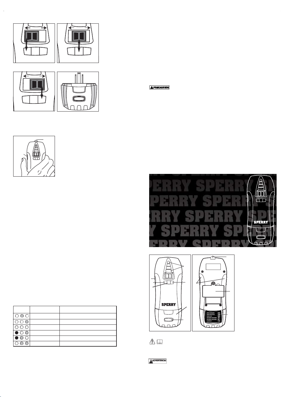
1. Wood and metal stud
detection
2. Metal pipe detection
3. AC volt detection
(50-600 VAC)
4. Calibration /
activation button
5. Over-molded soft
grips
6. 4 indication levels
indicate stud edge
7. GFCI test button
8. Metal marking tip
to mark location
of stud edge
9. Operates from 9 Volt
battery (included)
10. Removable 3-wire
outlet tester
11. Status Chart
5
9
11
8
!
!
!
Scan-Test
™
Escá ner y propador 5-en-1
• Lea atentamente este manual del propietario
antes de utilzar y guardar.
P
r
e
s
s
f
o
r
G
F
C
I
T
e
s
t
S
c
a
n
-
T
e
s
t
™
5-in-1 Scanner and Te ster
STUD METAL AC VOLT
P
r
e
s
s
t
o
S
c
a
n
Select
PD6902
SPERRY
INSTRUMENTS
Milwaukee,WI 53209 USA
Phone: 1-800-645-5398
www.sperryinstruments.com
1. Detecció n de espigas y
postes de madera y metal
2. Detecció n de tubería
de metal
3. Detecció n de voltaje
de CA (50 a 600 VCA)
4. Botó n de
calibració n / activació n
5. Agarres suaves
sobremoldeados
6. 4 niveles de indicació n
para señ alar el borde
del poste
7. Botó n de prueba
de GFCI
8. Punta metá lica para marcar
la ubicació n del borde del
poste
9. Funciona con baterías de 9
voltios (incluidas)
10. Probador de tomacorriente
de 3 conductores
desmontable
11. Cuadro de estado
P
r
e
s
s
f
o
r
G
F
C
I
T
e
s
t
S
c
a
n
-
T
e
s
t
™
5-in-1 Scanner and Te ster
STUD METAL AC VOLT
P
r
e
s
s
t
o
S
c
a
n
Selec t
1
2
7
3
10
6
4
5
9
11
8
!
!
!
¡PELIGRO!
!
!
¡PELIGRO!
!
STUD METAL AC VOLT
P
r
e
s
s
t
o
S
c
a
n
Select
Botón de
calibración
Indicador
visual
Fig. 1
1.0 METER FUNCTIONS
2.0 Read First: Important Safety Information
Read this operators manual thoroughly before using this tester. This manual is
intended to provide basic information regarding this tester and to describe
common test procedures which can be made with this unit. Many types of appliance,
machinery and other electrical circuit measurements are not addressed in this manual and
should be handled by experienced service technicians.
Use extreme caution when using this tester. Improper use of this tester
can result in severe damage to property, severe personal injury or death.
Follow all instructions and suggestions in this operators manual as well as observing
normal electrical safety precautions. Do not use this tester if you are unfamiliar with
electrical circuits and proper test procedures.
SAFETY WARNINGS
This instrument has been designed, manufactured and tested according to IEC61010: Safety
requirements for Electronic Measuring apparatus, and delivered in the best condition after
passing inspection. This instruction manual contains warnings and safety rules which must
be observed by the user to ensure safe operation of the instrument and retain it in safe
condition. Therefore, read through these operating instructions before using the instrument.
• Read through and understand the instructions contained in this manual before using the
instrument.
Keep the manual at hand to enable quick reference whenever necessary.
• The instrument is to be used only in its intended applications.
• Understand and follow all the safety instructions contained in the manual.
• It is essential that the above instructions are adhered to.
• Failure to follow the above instructions may cause injury, instrument damage and/or
damage to equipment under test.
is reserved for conditions and actions that can cause serious or fatal
injury.
is reserved for conditions and actions that can cause injury or
instrument damage.
Never make measurement on a circuit in which voltage over AC 600 V exists.
• Do not attempt to make measurement in the presence of flammable gasses. Otherwise, the
use of the instrument may cause sparking, which can lead to an explosion.
Never attempt to use the instrument if its surface or your hand is wet.
• Do not exceed the maximum allowable input of any measuring range.
• Never open the battery cover during a measurement.
• The instrument is to be used only in its intended applications or conditions. Otherwise,
safety functions equipped with the instrument don’t work, and instrument damage or
serious personal injury may be caused.
• Never attempt to make measurement if any abnormal conditions, such as broken case and
exposed metal parts are found on the instrument.
• Do not install substitute parts or make any modification to the instrument. For repair or
re-calibration, return the instrument to your local distributor from where it was purchased.
• Verify proper operation on a known source before use or taking action as a result of the
indication of the instrument.
Use appropriate personal protective equipment such as insulating gloves,
insulating boots, and safety glasses.
• Set the function switch to an appropriate position before starting measurement.
• Do not expose the instrument to the direct sun, high temperature and humidity or dewfall.
• Altitude 2000m or less. Appropriate operating temperature is within 0 °C and 32 °C.
• This instrument isn’t dust and water proofed. Keep away from dust and water.
• When the instrument will not be in use for a long period, place it in storage after removing the battery.
• Cleaning: Use a cloth dipped in water or neutral detergent for cleaning the instrument. Do not
use abrasives or solvents otherwise instrument may get damaged, deformed or discolored.
3.0 SPECIFICATIONS
• Stud detection depth and accuracy: 3/4"
+
⁄
-
1/8".
• Pipe detection depth: 2-1/2" through 1/2" drywall.
• AC volt detection distance/depth: 3-1/2" through 1/2" drywall.
• Operating Range: Non-contact AC Detector: 50-600 V AC 60 Hz; Plug in receptacle tester:
120 V AC 60 Hz
• Indicators: Audible and Visual
• Operating environment: 32 - 104 °F (0 - 32 °C) 80% RH max., 50% RH above 30 °C
Altitude up to 2000 meters.
Indoor use. Pollution degree 2. Accordance with IED-664.
• Battery: operates from one 9 Volt.
• Cleaning: Remove grease and grime with clean, dry cloth.
Marks listed below are used on this instrument.
User must refer to the manual.
Instrument with double or reinforced insulation.
Indicates that this instrument can touch bare conductors when measuring a voltage
corresponding to the applicable measurement, which is marked next to this symbol.
4.0 Operation
Combines all the functions necessary to accurately and
safely install 3 wire outlets, wall switches and lighting
fixtures in 4 easy steps. Detects wood or metal studs,
metal pipes and AC voltage hidden behind walls. Includes
a 3-wire outlet tester with GFCI test function to verify the
outlet has been wired properly.
NOTE: Low battery indicator: Before using, test the unit
for good batteries. Press and hold the “scan/calibration”
button on the side. If the batteries are low the middle “LED”
by the “metal” detection will flash. If low, replace with fresh
batteries. (Fig. 1)
STEP 1: Place the switch in
the “Stud” position (Fig. 2)
and scan the surface for
wood and metal studs. Mark
these locations with the
metal marking tip built into
the top of the tester.
STEP 2: Move the switch to
the “Metal” setting (Fig. 3)
and scan the surface for any
hidden metal pipes that
could interfere with the
installation.
STEP 3: Move the switch to
the “AC Volt” setting (Fig. 4)
and scan the surface a third
time to detect any live wires
behind the wall. Mark the
position of these wires if
they’re in proximity to the l-
ocation of the electrical box,
switch or fixture to be
installed.
STEP 4: After installation of
the new outlet, switch or
fixture, test the wiring with
the attached outlet tester
(Fig. 5) or non-contact AC
Volt sensing tip.
4.1 Stud detection (wood and metal)
a. Position the select switch in the “Stud” position. (Fig. 2)
b. Place the unit flat against the surface to be scanned. (Fig.
6)
c. Press the calibrate/activate button located on the side to
calibrate the unit.
Continue to press and hold this button while sliding the
unit across the surface.
d. As the unit approaches a stud edge the LEDs will start to
illuminate, until they reach the top. This indicates the stud
edge.
e. Mark the stud edge with the metal marking tip built into
the top of the tester.
f. To find the middle of the stud, scan again from the
opposite direction and mark the stud edge. The center
between the two marked points is the center of the stud.
4.2 Metal Pipe detection
a. Position the “select” switch in the “Metal” position. (Fig. 3)
b. Place the unit flat against the surface to be scanned.
c. Press the calibrate/activate button located on the side to activate the test. Continue to
press and hold this button while sliding the unit across the surface. (Fig. 6)
d. As the unit approaches a metal pipe the LEDs will start to illuminate, until they reach the
top. This indicates the location of the metal pipe.
e. Mark this location with the metal marking tip built into the top ofthe tester.
4.3 AC Voltage Detection
a. Position the select switch in the “AC Volt” position. (Fig. 4)
b. Place the unit flat against the surface or position the nose close to the surface to be scanned.
c. Press the calibrate/activate button located on the side to activate the test. Continue to
press and hold this button while sliding the unit across the surface. (Fig. 6)
d. As the unit approaches a “live” 50 V AC or higher source, such as a wire, the unit will give
off both an audible and visual signal indicating the presence of AC voltage.
4.4 Receptacle tester
1. Detach the receptacle tester from the scanner housing.
2. Plug the tester into any 120 Volt standard or GFCI outlet.
3. View the indicators on the tester and match with the chart on the tester. (Fig. 7)
4. If the tester indicates a wiring problem then turn off all power to the outlet and repair
wiring. (Consult an electrician if necessary)
5. Restore power to the outlet and repeat steps 1-3.
To test GFCI Protected Outlets:
1. Consult the GFCI manufacturer’s installation instructions to determine that the GFCI is
installed in accordance with the manufacturer’s specifications.
2. Check for correct wiring of receptacle and all remotely connected receptacles on the
branch circuit.
3. Operate the test button on the GFCI installed in the circuit. The GFCI must trip. If it
doesn’t, do not use the circuit and consult an electrician. If the GFCI does trip, reset the
GFCI. Then, insert the GFCI tester into the receptacle to be tested.
4. Activate the test button on the GFCI tester for a minimum of 6 seconds when testing the
GFCI condition. Visible indication on the GFCI tester must cease when tripped.
5. If the tester fails to trip the GFCI, it suggests:
a.) a wiring problem with a totally operable GFCI, or
b.) proper wiring with a faulty GFCI. Consult with an electrician to check the condition of
the wiring and GFCI.
When testing GFCIs installed in 2- wire systems (no ground wire available), the tester may
give a false indication that the GFCI is not functioning properly. If this occurs, recheck the
operation of the GFCI using the test and reset buttons.The GFCI button test function will
demonstrate proper operation.
NOTE:
1. All appliances or equipment on the circuit being tested should be unplugged to help avoid
erroneous readings.
2. Not a comprehensive diagnostic instrument but a simple instrument to detect nearly all
probable common improper wiring conditions.
3. Refer all indicated problems to a qualified electrician.
4. Will not indicate quality of ground.
5. Will not detect two hot wires in a circuit.
6. Will not detect a combination of defects.
7. Will not indicate a reversal of grounded and grounding conductors.
5.0 Replacing the batteries.
This unit operates from a standard 9 Volt battery. To replace, remove the battery door cover,
located on the back, with a small screwdriver. Replace with new battery and then shut the
battery door and replace screw. (Refer to 1.0, Meter Functions)
1.0
FUNCIONES DEL MEDIDOR
2.0 Leer primero: Informació n de seguridad importante
Lea completamente este manual del operador antes de usar este medidor. Este
manual está destinado a dar informació n bá sica referente a este medidor y
describir procedimientos de prueba comunes que se pueden realizar con esta unidad.
Muchos tipos de mediciones de artefactos, maquinaria y otros circuitos elé ctricos no se
tratan en este manual y deben realizarlas los té cnicos de servicio experimentados.
Sea precavido al utilizar este medidor. El uso indebido de este medidor
puede causar dañ os materiales severos y lesiones físicas graves o fatales.
Siga todas las instrucciones y sugerencias en este manual del operador y tambié n
observe las precauciones normales de seguridad elé ctrica. No use este medidor si no
está familiarizado con circuitos elé ctricos y los procedimientos de prueba apropiados.
ADVERTENCIAS DE SEGURIDAD
Este instrumento ha sido diseñ ado, fabricado y probado conforme a IEC61010: Requisitos
de seguridad para aparatos electró nicos de medició n, y se entrega en el mejor estado
despué s de pasar la inspecció n. Este manual de instrucciones contiene advertencias y
reglas de seguridad que el usuario debe observar para garantizar el funcionamiento seguro
del instrumento y mantener su buen estado sin presentar peligro. Por lo tanto, lea estas
instrucciones operativas antes de usar el instrumento.
• Lea totalmente y en detalle las instrucciones contenidas en este manual antes
de usar el instrumento.
• Conserve a mano el manual para poder usarlo a modo de referencia rá pida siempre que
sea necesario.
• El instrumento debe usarse solamente en las aplicaciones contempladas.
• Siga minuciosamente todas las instrucciones de seguridad contenidas en el manual.
• Es esencial que se respeten las instrucciones anteriores.
• Si no se siguen las instrucciones anteriores puede causar lesiones, dañ o al instrumento
y/o dañ o al equipo a prueba.
se reserva para condiciones y acciones que pueden causar lesiones
serias o fatales.
se reserva para condiciones y acciones que pueden causar lesiones o
dañ os al instrumento.
• Nunca tome medidas en un circuito donde exista voltaje sobre 600 V de CA.
• No intente tomar medidas en la presencia de gases inflamables.De lo contrario, el uso del
instrumento puede causar chispas, lo cual puede ocasionar una explosió n.
• Nunca intente usar el instrumento si está mojada la superficie o la mano.
• No supere la entrada má xima permisible de cualquier rango de medició n.
• Nunca abra la tapa de la batería durante una medició n.
• El instrumento debe usarse solamente en las aplicaciones o condiciones contempladas.
De lo contrario, las funciones de seguridad con las cuales se ha equipado el instrumento
quedan inoperantes, y puede causarse dañ o al instrumento o lesiones físicas serias.
• Nunca intente tomar medidas si se encuentra alguna condició n anormal, como con la caja
rota o piezas metá licas expuestas en el instrumento.
• No sustituya piezas ni haga modificaciones al instrumento. Para reparar o recalibrar el
instrumento, devué lvalo a su distribuidor local donde lo compró .
• Verifique el funcionamiento correcto en una fuente conocida antes de usar o de actuar
basá ndose en lo que indicó el instrumento.
• Use el equipo protector personal adecuado como guantes aisladores,
botas aisladoras y anteojos de seguridad.
• Ponga el interruptor de funció n en una posició n adecuada antes de comenzar a medir.
• Inserte firmemente los conductores de prueba.
• No exponga el instrumento al sol directo, a alta temperatura ni humedad o caída de rocío.
• Altitud de 2000 m o menor. La temperatura operativa adecuada está entre 0°C y 40°C.
• Este instrumento no es a prueba de polvo ni agua. Manté ngalo alejado del polvo y del agua.
• Confirme que se haya apagado el instrumento despué s del uso. Cuando el instrumento no
vaya a estar en uso por un tiempo largo, pó ngalo en almacenamiento despué s de extraerle
las baterías.
• Limpieza: Use un pañ o sumergido en agua o detergente neutro para limpiar el
instrumento. No use abrasivos ni solventes, de lo contrario el instrumento puede dañ arse,
deformarse o decolorarse.
Secció n 3.0 Especificaciones
• Profundidad y precisió n de la detecció n de espigas: 19 mm +/- 3.2 mm.
• Profundidad de detecció n de tubería: 64 mm a travé s de panel de yeso de 13 mm.
• Profundidad o distancia de detecció n de voltaje de CA: 89 mm a travé s de panel de yeso
de 13 mm.
• Rango operativo:
Detecció n de voltaje CA sin contacto 50-600 VCA, 60 Hz;
CAT III 600V
Receptá culo del probador enchufado: 120 VCA 60 Hz
• Indicadores: Sonoros y visuales
• Ambiente operativo: 0 -32 °C 80% humedad relativa má x., 50% humedad relativa sobre los
30 °C Altitud hasta 2000 metros. Uso en interiores. Grado de contaminació n 2.
Conformidad con IED-664.
• Batería: opera con una batería de 9 voltios.
• Limpieza: Retire la grasa y la mugre con un pañ o seco y limpio.
Se usan las marcas indicadas en la tabla a continuació n en este instrumento.
El usuario debe consultar el manual.
Instrumento con aislamiento doble o reforzado.
Indica que este instrumento puede tocar conductores desnudos al medir un voltaje
correspondiente a la medició n aplicable, la cual está marcada junto a este símbolo.
4.0 Funcionamiento
Combina en 4 pasos fá ciles todas las funciones necesarias
para instalar en forma precisa y segura receptá culos de 3
conductores, tomacorrientes y lá mparas o luminarias.
Detecta espigas de madera o metal, tuberías de metal y
voltaje de CA ocultas detrá s de las paredes. Incluye un
probador de receptá culo de 3 conductores con funció n de
prueba GFCI para verificar que el tomacorriente tiene el
cableado correcto.
NOTA:
Indicador de batería baja: Antes de usar, confirme que la
unidad tenga buenas baterías. Presione y mantenga así el
botó n “escanear/calibració n” en el lado. Si las baterías está n
bajas destellará la luz indicadora central junto a la detecció n
de “metal”. Si está n bajas, reemplá celas por baterías
frescas. (Fig. 1)
Scan-Test
™
5-in-1 Scanner and Tester
• Read this owners manual thoroughly
before use and save.
P
r
e
s
s
f
o
r
G
F
C
I
T
e
s
t
S
c
a
n
-
T
e
s
t
™
5-in-1 Scanner and Tester
STUD METAL AC VOLT
P
r
e
s
s
t
o
S
c
a
n
Select
PD6902
SPERRY
INSTRUMENTS
Milwaukee,WI 53209 USA
Phone: 1-800-645-5398
www.sperryinstruments.com
P
r
e
s
s
f
o
r
G
F
C
I
T
e
s
t
S
c
a
n
-
T
e
s
t
™
5-in-1 Scanner and Tes ter
STU D METAL AC VOLT
P
r
e
s
s
t
o
S
c
a
n
Select
1
2
7
3
10
6
4
!
!
STUD METAL AC VOLT
P
r
e
s
s
t
o
S
c
a
n
Select
Calibrate
Button
Visual
Indicator
Fig. 1
Fig. 6
S
STUD METAL AC VOLT
P
r
e
s
s
t
o
S
c
a
n
Select
Calibrate
Button
Metal
Marking Tip
Fig. 7
Indicator Fault Reason for Wiring Fault
Ground contact not connected
Neutral contact not connected
Hot and ground contacts interchanged
Hot and neutral contacts interchanged
Receptacle is wired correctly
Open Ground
Open Neutral
Open Hot
Hot/Ground/Reverse
Hot/Neutral/Reverse
Correct
Hot contact not connected
STUD METAL AC VOLT
P
r
e
s
s
t
o
S
c
a
n
Select
STUD METAL AC VOLT
P
r
e
s
s
t
o
S
c
a
n
Select
STUD METAL AC VOLT
e
s
s
t
o
S
c
a
n
Select
Fig. 2
Fig. 3
Fig. 4
Fig. 5
1. Wood and metal stud
detection
2. Metal pipe detection
3. AC volt detection
(50-600 VAC)
4. Calibration /
activation button
5. Over-molded soft
grips
6. 4 indication levels
indicate stud edge
7. GFCI test button
8. Metal marking tip
to mark location
of stud edge
9. Operates from 9 Volt
battery (included)
10. Removable 3-wire
outlet tester
11. Status Chart
5
9
11
8
!
!
!
Scan-Test
™
Escá ner y propador 5-en-1
• Lea atentamente este manual del propietario
antes de utilzar y guardar.
P
r
e
s
s
f
o
r
G
F
C
I
T
e
s
t
S
c
a
n
-
T
e
s
t
™
5-in-1 Scanner and Te ster
STUD METAL AC VOLT
P
r
e
s
s
t
o
S
c
a
n
Select
PD6902
SPERRY
INSTRUMENTS
Milwaukee,WI 53209 USA
Phone: 1-800-645-5398
www.sperryinstruments.com
1. Detecció n de espigas y
postes de madera y metal
2. Detecció n de tubería
de metal
3. Detecció n de voltaje
de CA (50 a 600 VCA)
4. Botó n de
calibració n / activació n
5. Agarres suaves
sobremoldeados
6. 4 niveles de indicació n
para señ alar el borde
del poste
7. Botó n de prueba
de GFCI
8. Punta metá lica para marcar
la ubicació n del borde del
poste
9. Funciona con baterías de 9
voltios (incluidas)
10. Probador de tomacorriente
de 3 conductores
desmontable
11. Cuadro de estado
P
r
e
s
s
f
o
r
G
F
C
I
T
e
s
t
S
c
a
n
-
T
e
s
t
™
5-in-1 Scanner and Te ster
STUD METAL AC VOLT
P
r
e
s
s
t
o
S
c
a
n
Selec t
1
2
7
3
10
6
4
5
9
11
8
!
!
!
¡PELIGRO!
!
!
¡PELIGRO!
!
STUD METAL AC VOLT
P
r
e
s
s
t
o
S
c
a
n
Select
Botón de
calibración
Indicador
visual
Fig. 1
PASO 1: Coloque el
interruptor en la posició n
“Stud” (Fig. 2) (Espiga) y
recorra la superficie en
busca de espigas de
madera y metal. Marque
estos lugares con la punta
de marcado metá lica
incorporada en la parte
superior del probador.
PASO 2: Coloque el
interruptor en la posició n
“Metal” (Fig. 3) y recorra la
superficie en busca de
tuberías de metal ocultas
que pudieran interferir con la
instalació n.
PASO 3: Mueva el
interruptor a la posició n “AC
Volt” y recorra por tercera
vez la superficie para
detectar cualquier cable
elé ctrico con energía detrá s
de la pared. Marque la
posició n de estos cables si
está n cerca de la ubicació n
de l a caja elé ctrica,
interruptor o luminaria a
instalar.
PASO 4: Despué s de la instalació n del nuevo tomacorriente, interruptor o luminaria pruebe
el cable con el probador de tomacorriente incluido o con el detector sin contacto. (Fig. 5)
4.1 Detecta espigas y postes (de metal y madera)
a. Coloque el interruptor de selecció n en la posició n “Stud”
(Fig. 2) (Espiga).
b. Coloque la unidad plana contra la superficie que se va a
explorar. (Fig. 6)
c. Presione el botó n de calibració n/activació n ubicado en el
lado, para calibrar la unidad. Continú e presionando este
botó n mientras desliza la unidad por la superficie.
d. A medida que la unidad se acerca al borde de una espiga
se comenzará n a iluminar las luces indicadoras, hasta que
lleguen a la parte superior. Esto indica el borde de la espiga.
e. Marque el borde de la espiga con la punta de marcado
metá lica incorporada en la parte superior del probador.
(show application line drawing for this feature.)
f. Para encontrar el centro de un poste, escanee nuevamente desde la direcció n opuesta y
marque el borde del poste. El centro entre ambos puntos marcados es el centro del poste.
4.2 Detecció n de tubería de metal
a. Coloque el interruptor de selecció n en la posició n “Metal” (Fig. 2) .
b. Coloque la unidad plana contra la superficie que se va a explorar.
c. Presione el botó n de calibració n/activació n ubicado en el lado, para activar la prueba.
Continú e presionando este botó n mientras desliza la unidad por la superficie.(Fig. 6)
d. A medida que la unidad se acerca a una tubería de metal se comenzará n a iluminar las
luces indicadoras, hasta que lleguen a la parte superior. Esto indica la ubicació n de la
tubería de metal.
e. Marque este lugar con la punta de marcado metá lica incorporada en la parte superior del
probador.
4.3 Detecció n de voltaje de CA
a. Coloque el interruptor de selecció n en la posició n “AC Volt” (Voltaje de CA).(Fig. 3)
b. Coloque la unidad plana contra la superficie o ubique la punta cerca de la superficie que
se va a explorar.
c. Presione el botó n de calibració n/activació n ubicado en el lado, para activar la prueba.
Continú e presionando este botó n mientras desliza la unidad por la superficie.(Fig. 6)
d. A medida que la unidad se aproxima a una fuente “energizada” de 50 voltios o mayor,
como un cable, la unidad dará una señ al tanto sonora como visual indicando la presencia
de voltaje de CA.
4.4 Probador de receptá culos
1. Separe el probador de receptá culos del alojamiento del escá ner.
2. Enchufe el probador en cualquier tomacorriente está ndar de 120 Voltios o de GFCI [circuito
de falla por puesta a tierra].
3. Vea los indicadores en el probador y compá relos con la tabla del probador. (Fig. 7)
4. Si el probador indica un problema de cableado apague toda la alimentació n al
tomacorriente y repare el cableado. (Si es necesario consulte con un electricista)
5. Restablezca la alimentació n al tomacorriente y repita los pasos 1-3.
Para probar los tomacorrientes protegidos GFCI:
1.Consulte las instrucciones de instalació n de fabricante del GFCI para determinar que el GFCI
está instalado de acuerdo con las especificaciones del fabricante.
2.Verifique el cableado correcto del receptá culo y todos los receptáculos conectados en forma
remota en el ramal del circuito.
3.Opere el botó n de prueba en el GFCI instalado en el circuito. El GFCI debe dispararse. Si no lo
hace, no use el circuito y consulte con un electricista. Si se dispara el GFCI, reajuste el GFCI.
Luego, inserte el probador de GFCI en el receptáculo a probar.
4.Active el botó n de prueba en el probador de GFCI por un mínimo de 6 segundos cuando
esté probando la condició n del GFCI. Cuando se haya disparado debe terminar la indicació n
visible del probador de GFCI.
5.Si el probador no dispara el GFCI, indica:
a.) un problema de cableado con un GFCI totalmente operable, o
b.) cableado apropiado con un GFCI fallado.Consulte con un electricista para verificar la
condició n del cableado y del GFCI.
Al probar GFCI instalados en sistemas de 2 cables (sin conexió n a
tierra), el probador puede dar una indicació n falsa de que el GFCI no
está funcionando bien. En este caso, vuelva a verificar la operació n del GFCI usando
los botones de prueba y reajuste. La funció n de prueba del botó n GFCI demostrará la
operació n apropiada.
NOTA:
1. Deben desenchufarse todos los artefactos o equipo en el circuito que se está probando
para ayudar a evitar las lecturas erró neas.
2. No se trata de un instrumento de diagnó stico integral, sino má s bien de un instrumento
simple para detectar casi todas las condiciones probables de cableado indebido que son
comunes.
3. Remita todos los problemas indicados a un electricista competente.
4. No indica la calidad de la conexió n a tierra.
5. No detecta dos cables energizados dentro de un circuito.
6. No detecta una combinació n de defectos.
7. No indica conductores de tierra o puestos a tierra invertidos.
5.0 Reemplazo de las baterías.
Esta unidad funciona con una batería de 9 voltios está ndar. Para reemplazarla, usando un
destornillador pequeñ o, retire la cubierta de la puerta de baterías, ubicada en la parte
posterior. Reemplace por una batería nueva y luego cierre la puerta de la batería y vuelva a
colocar el tornillo. (Consulte 1.0, Funciones del medidor)
1.0 METER FUNCFONCTIONS DU COMPTEURTIONS
2.0 À lire au pré alable
Informations importantes sur la sé curité
Bien lire le pré sent manuel de l’opé rateur avant d’utiliser ce compteur. Ce manuel
vise à donner des informations de base concernant le compteur et à dé crire les procé dures
d’essai courantes que l’appareil permet de faire. De nombreuses mesures d’appareils
é lectriques, de machinerie et d’autres circuits é lectriques ne sont pas traité es dans le
pré sent manuel et devraient ê tre effectué es par des techniciens expé rimenté s.
Il faut faire extrê mement attention lorsqu’on utilise ce compteur. Une mauvaise
utilisation peut causer des dommages matériels graves, des blessures
sérieuses et mê me la mort. Suivre les instructions et les suggestions du pré sent manuel
et respecter les mesures de sé curité é lectrique normales. Ne pas utiliser ce compteur
si on ne connaît pas les circuits é lectriques et les procé dures d’essai approprié es.
AVERTISSEMENTS CONCERNANT LA SÉ CURITÉ
Le pré sent instrument a é té conç u, fabriqué et essayé conformé ment à la norme IEC61010 :
Safety requirements for Electronic Measuring (mesures de sé curité pour les appareils de
mesure é lectroniques), et il est livré dans le meilleur é tat après l’inspection. Le pré sent manuel
d’instructions contient des avertissements et des rè gles de sé curité qui doivent ê tre observé es
par l’utilisateur afin d’assurer la sé curité de fonctionnement de l’instrument et de le garder en
bon é tat. Il faut donc lire ces instructions de fonctionnement avant d’utiliser l’instrument.
• Bien lire et comprendre les instructions contenues dans le pré sent manuel avant
d’utiliser l’instrument.
• Garder le manuel à porté e de la main pour une ré fé rence rapide si c’est né cessaire.
• L’instrument ne doit ê tre utilisé que pour l’usage pré vu.
• Bien comprendre et suivre toutes les instructions de sé curité continues dans le présent manuel.
• Il est essentiel que les instructions ci-dessus soient respecté es.
• Le non-respect des instructions ci-dessus peut causer des blessures, endommager
l’instrument et/ou l’é quipement vé rifié.
ré servé pour les conditions et les mesures qui peuvent causer des blessures
graves ou mortelles.
ré servé pour les conditions et les mesures qui peuvent causer des
blessures ou endommager l’instrument.
• Ne jamais prendre de mesure sur un circuit soumis à une tension de plus de
600 V c.a.
• Ne pas tenter de prendre des mesures en pré sence de gaz inflammables. En effet, l’utilisation
de l’instrument peut causer des é tincelles qui peuvent dé clencher une explosion.
Ne jamais tenter d’utiliser l’instrument si la surface de celui-ci ou la main de
l’utilisateur est mouillé e.
• Ne pas dé passer l’entré e maximale autorisé e pour une plage de mesure quelconque.
• Ne jamais ouvrir le couvercle de la pile durant une mesure.
• L’instrument ne doit ê tre utilisé que pour les usages ou les conditions pré vus. Sinon, les
functions de sé curité de l’instrument sont hors service, ce qui peut endommager
l’instrument ou causer des blessures.
• Ne jamais prendre de mesure si l’instrument pré sente des conditions anormales comme
un boîtier brisé ou des piè ces mé talliques exposé es.
• Ne pas installer de piè ces de remplacement ni modifier l’instrument. Pour la ré paration ou
le ré é talonnage, retourner l’instrument au distributeur local à qui il a é té acheté .
• Dé brancher tous les cordons et câ bles de l’objet à vé rifier et couper l’alimentation de
l’instrument avant d’ouvrir le couvercle de la pile pour remplacer celle-ci.
• Vé rifier le bon fonctionnement sur une source connue avant d’utiliser l’instrument ou de
dé cider d’une mesure à la suite de l’indication donné e par l’instrument.
• Utiliser l’é quipement de protection personnelle approprié : gants et bottes
isolants et lunettes de sé curité .
• Ré gler le sé lecteur de fonction à la protection appropriée avant de commencer une mesure.
• Insé rer fermement les fils d’essai.
• Ne pas exposer l’instrument aux rayons directs du soleil, à des tempé ratures é levé es et à
l’humidité ou à la rosé e.
• Altitude : 2000 m ou moins. Plage de tempé rature de fonctionnement: 0 °C à 40 °C.
• L’instrument n’est pas à l’é preuve de la poussiè re ou de l’eau. Le garder loin de la poussiè re et
de l’eau.
• S’assurer d’éteindre l’instrument après usage. Quand l’instrument n’est pas utilisé pendant
une longue pé riode, le ranger après avoir retiré les piles.
• Nettoyage : Nettoyer l’appareil avec un linge trempé dans l’eau ou dans un dé tergent
neutre. Ne pas utiliser d’abrasifs ou de solvants sinon l’instrument peut ê tre endommagé ,
dé formé ou dé coloré .
3.0 CARACTÉ RISTIQUES
• Profondeur et pré cision de dé tection des montants : 19 mm +⁄- 3,2 mm.
• Profondeur de dé tection des tuyaux : 64 mm à travers une cloison sè che de 13 mm.
• Distance/profondeur de dé tection des tensions c.a. : 89 mm à travers une cloison sè che
de 13 mm.
• Plage de fonctionnement : Dé tecteur de tension c.a. sans contact : 50-600 V c.a., 60 Hz;
Vé rificateur de prise branchable : 120 V c.a., 60 Hz
• Indicateurs: Visuels et sonores
• Environnement de fonctionnement : 0 - 32 °C, 80 % HR max.,50 % HR au-dessus de 30
°C , altitude jusqu’à 2000 mè tres. Pour usage à l’inté rieur. Degré 2 de pollution,
conformé ment à la norme IEC-664
• Pile : Une pile de 9 volts.
• Nettoyage : Retirer graisse et saleté avec un chiffon propre et sec.
Les marques indiqué es dans le tableau ci-dessous sont utilisé es pour cet instrument.
L’utilisateur peut consulter le manuel.
L’instrument a une isolation double ou renforcé e.
Ceci indique que l’instrument peut toucher des conducteurs nus quand on mesure une
tension correspondant à la mesure applicable qui est marqué e à cô té de ce symbole.
4.0 Fonctionnement
L’instrument ré unit toutes les fonctions né cessaires pour
installer avec pré cision et sé curité les prises à 3 fils, les
interrupteurs muraux et les appareils d’é clairage. Il
dé tecte les montants de bois ou de mé tal, les tuyaux
mé talliques et les sources de tension c.a. derriè re les
murs. Il comprend un vé rificateur de prise à 3 fils avec une
fonction de disjoncteur de dé faut à la terre pour vé rifier
que la prise a é té bien branché e.
REMARQUE: Indicateur de dé charge de batterie : Avant
d'utiliser l'unité , il faut en tester les batteries. Appuyer et
maintenir enfoncé le bouton « balayage/
calibrage » sur le cô té . Si les batteries sont faibles, le voyant
DEL du milieu à cô té de la dé tection « mé tal » clignotera. Si
les batteries sont faibles, il faut les remplacer.(Fig. 1)
É TAPE 1. Placer le sé lecteur
à la position « Stud »
(montant) (Fig. 2) et balayer
la surface pour rechercher les
montants de bois et de mé tal.
Marquer ces emplacements
avec la pointe de marquage
pour mé tal au sommet du
vé rificateur.
É TAPE 2. Mettre le sé lecteur
sur « Mé tal » (Fig. 3) et
balayer la surface pour
rechercher les tuyaux
mé talliques caché s qui
pourraient gê ner l’installation.
É TAPE 3. Placer le sé lecteur
à la position « AC Volt » (Fig.
4) (tension c.a.) et balayer la
surface une troisiè me fois pour
dé tecter tous les fils porteurs
derriè re le mur. Marquer la
position de ces fils s’ils sont à
proximité d’une boîte
é lectrique, d’un interrupteur ou
d’un appareil à installer.
É TAPE 4. Aprè s l’installation
de la nouvelle prise, du nouvel
interrupteur ou appareil, vé rifier
le câ blage avec le contrô leur
(Fig. 5) sur la prise ou avec un
détecteur sans contact.
4.1 Dé tection des montants (bois et mé tal)
a. Placer le sé lecteur à la position « Stud » (montant). (Fig. 2)
b. Placer l’appareil à plat contre la surface à balayer. (Fig. 6)
c. Appuyer sur le bouton d’é talonnage/activation qui se
trouve sur le cô té pour é talonner l’appareil. Continuer à
appuyer sur le bouton et le tenir enfoncé tout en glissant
l’appareil sur la surface.
d. À mesure que l’appareil approche du bord d’un montant,
les DÉ L commencent à s’allumer jusqu’à se qu’elles
atteignent le sommet. Cela indique le bord du montant.
e. Marquer le bord du montant avec la pointe de marquage
pour mé tal au sommet du vé rificateur. (Monter un dessin
liné aire d,application pour cette fonction.)
4.2 Dé tection des tuyaux de mé tal
a. Placer le sé lecteur à la position « Metal » (mé tal). (Fig. 3)
b. Placer l’appareil à plat contre la surface à balayer.
c. Appuyer sur le bouton d’é talonnage/activation qui se trouve sur le cô té pour commencer
le test. Continuer à appuyer sur le bouton et le tenir enfoncé tout en glissant l’appareil sur
la surface. (Fig. 6)
d. À mesure que l’appareil approche du tuyau mé tallique, les DÉ L commencent à s’allumer
jusqu’à se qu’elles atteignent le sommet. Ceci indique l’emplacement du tuyau mé tallique.
e. Marquer cet emplacement avec la pointe de marquage pour mé tal au sommet du vé rificateur.
4.3 Dé tection d’une tension c.a.
[Ajouter des dessins liné aires/artistiques pour bien montrer les ré glages et les usages]
a. Placer le sé lecteur à la position « AC Volt » (tension c.a.). (Fig. 4)
b. Placer l’appareil à plat contre la surface ou placer le nez contre la surface à balayer.
c. Appuyer sur le bouton d’é talonnage/activation qui se trouve sur le cô té pour commencer
le test. Continuer à appuyer sur le bouton et le tenir enfoncé tout en glissant l’appareil sur
la surface. (Fig. 6)
d. À mesure que l’appareil approche d’un fil sous tension de 120 volts ou plus, il é met un
signal sonore et visuel indiquant la pré sence d’une tension c.a.
4.4 Vé rificateur de prise
1. Dé tacher le vé rificateur de prise du boîtier de balayage.
2.Brancher l’appareil dans la prise nouvellement installée ou toute autre prise à 3 fils de 120 V c.a.
3. Observer les DÉ L et verifier avec le tableau d’é tat qui se trouve sur le logement. (Fig. 7)
4.Si le vé rificateur indique un problè me de câ blage, couper le courant vers la prise et ré parer le
câ blage. (Consulter un électricien au besoin)
Pour vé rifier les prises avec disjoncteur de dé faut à la terre (GFCI):
1. Consulter les instructions d’installation du fabricant du disjoncteur de dé faut à la terre
pour é tablir si le disjoncteur est bien installé conformé ment aux spé cifications.
2. Vé rifier que la prise et toutes celles qui sont branché es sur le circuit sont bien câ blé es.
3. Appuyer sur le bouton d’essai du disjoncteur de dé faut à la terre installé sur le circuit. Le
disjoncteur de dé faut à la terre doit se dé clencher. Sinon, il ne faut pas utiliser le circuit et
il faut consulter un é lectricien. Si le disjoncteur de dé faut à la terre se dé clenche, il faut le
ré enclencher. Ensuite, il faut insé rer le vé rificateur du disjoncteur de dé faut à la terre dans
la prise à vé rifier.
4. Actionner le bouton d’essai du vé rificateur du disjoncteur de dé faut à la terre pendant un
minimum de 6 secondes quand on vé rifie l’état du disjoncteur. L’indication visible sur le
vé rificateur du disjoncteur de dé faut à la terre doit cesser quand celui-ci se dé clenche.
5. Si le vé rificateur ne dé clenche pas le disjoncteur, cela suggè re :
a) un problè me de câ blage avec un disjoncteur de dé faut à la terre en bon é tat de
fonctionnement, ou
b) un bon câ blage avec un disjoncteur dé fectueux. Consulter un é lectricien pour vé rifier
l’é tat du câ blage et le disjoncteur de dé faut à la terre.
Quand on vé rifie les disjoncteurs de dé faut à la terre installé s dans des
systè mes à 2 fils (sans fil de terre), le vé rificateur peut indiquer à tort que le
disjoncteur ne fonctionne pas bien. Si cela se produit, vé rifier de nouveau le fonctionnement
du disjoncteur de dé faut à la terre avec les boutons d’essai et de ré enclenchement.
Le bouton d’essai du disjoncteur de dé faut à la terre montrera le bon fonctionnement.
REMARQUE:
1. Tous les appareils et é quipements é lectriques du circuit vé rifié devraient ê tre dé branché s
pour aider à é viter les indications erroné es.
2. Cet appareil n’est pas un appareil de diagnostic complet mais un instrument qui permet
simplement de dé tecter presque toutes les conditions probables et courantes de mauvais
câ blage.
3. Indiquer tous les problè mes indiqué s à un é lectricien qualifié .
4. L’appareil n’indiquera pas la qualité de la mise à la terre.
5. Il ne dé tectera pas deux fils porteurs dans un circuit.
6. Il ne dé tectera pas une combinaison de dé fauts.
7. Il n’indiquera pas une inversion des conducteurs relié s à la terre ou de la mise à la terre.
5.0 Remplacer les batteries.
Cette unité fonctionne avec une batterie de 9 volts. Pour remplacer la batterie, enlever le
couvercle du ré ceptacle de la batterie, situé e à l'arriè re, à l'aide d'un petit tournevis.
Remplacer la batterie par une neuve, puis refermer la porte du ré ceptacle et remettre la vis.
(se ré fé rer à la section 1.0, Fonctions de l'unité )
Fig. 6
STUD METAL AC VOLT
P
r
e
s
s
t
o
S
c
a
n
Sele ct
Botón de
calibración
Punta de
marcado
metáli ca
STUD METAL AC VOLT
P
r
e
s
s
t
o
S
c
a
n
Select
STUD METAL AC VOLT
P
r
e
s
s
t
o
S
c
a
n
Select
STUD METAL AC VOLT
e
s
s
t
o
S
c
a
n
Select
Fig. 2
Fig. 3
Fig. 4
Fig. 5
Fig. 7
Indicador Falla Razon de la Falla a Tierra
El contacto a tierra no está conectado
El contacto neutro no está conectado
Los contactos energizado y a tierra
está n intercambiados
Los contactos energizado y neutro
está n intercambiados
El receptá culo está conectado correctamente
Tierra abierto
Neutro abierto
Energizado abierto
Energizado/Tierra
invertidos
Energizado/Neutro
invertidos
Correcto
El contacto energizado no está conectado
!
Scan-Test
™
Balayeur et testeur 5-en-1
•
Lisez ce manuel entié rement avant
utilisation et rangez-le soigneusement.
P
r
e
s
s
f
o
r
G
F
C
I
T
e
s
t
S
c
a
n
-
T
e
s
t
™
5-in-1 Scanner and Tester
STUD METAL AC VOLT
P
r
e
s
s
t
o
S
c
a
n
Select
PD6902
SPERRY
INSTRUMENTS
Milwaukee, WI 53209 USA
Phone: 1-800-645-5398
www.sperryinstruments.com
1. Dé tection de montants de
bois et
de mé tal
2. Dé tection de tuyaux de
mé tal
3. Dé tection de tension
alternative
(50-600 VAC)
4. Bouton de calibrage ou
d'activation
5. Poigné es surmoulé es
souples
6. Quatre voyants indiquant le
bord
du montant
7. Bouton de test GFCI
8. Pointe en mé tal pour
marquer l'emplacement du
bord
du montant
9. Fonctionne avec une
batterie de 9 volts (incluse)
10.Testeur amovible à prise
de trois fiches
11.Tableau de statut
P
r
e
s
s
f
o
r
G
F
C
I
T
e
s
t
S
c
a
n
-
T
e
s
t
™
5-in-1 Scanner and Te ster
STU D METAL AC VOLT
P
r
e
s
s
t
o
S
c
a
n
Select
1
2
7
3
10
6
4
5
9
11
8
!
!
!
!
STUD METAL AC VOLT
P
r
e
s
s
t
o
S
c
a
n
Select
Bouton de
calibrage
Indicateur
visuel
Fig. 1
STUD METAL AC VOLT
P
r
e
s
s
t
o
S
c
a
n
Select
STUD METAL AC VOLT
P
r
e
s
s
t
o
S
c
a
n
Select
STUD METAL AC VOLT
e
s
s
t
o
S
c
a
n
Select
Fig. 2
Fig. 3
Fig. 4
Fig. 5
Fig. 6
STUD METAL AC VOLT
P
r
e
s
s
t
o
S
c
a
n
Select
Pointe de
marquage
pour
métal
Bouton de
calibrage
Fig. 7
Indicateur Dé faut Raison de Dé faut de Cablage
Contact de terre non connecté
Contact neutre non connecté
Contacts tension et terre inversé s
Contacts tension et neutre inversé es
La prise est correctement câ blé e
Circuit de terre ouvert
Circuit neutre ouvert
Circuit sous
tension ouvert
Tension / terre
inversé es
Tension / neutre
inversé s
Correct
Contact sous tension non connecté