Loading ...
Loading ...
INSTALLATION INSTRUCTIONS
2
1
/4"
(57mm)
Knockout
Location
Knockout
Location
1
1
/
2
"
(38mm)
*3
3
/4"
(95mm)
2
1
/4"
(57mm)
1. All electrical work and materials must comply
with the National Electric Code (NEC), the Occu-
pational Safety and Health Act (OSHA), and all
state and local codes.
2. Use copper conductors only.
3. Do not install below an electrical receptacle.
4. A heater has hot and arcing or sparking parts
inside. Do not use it in areas where gasoline,
paint, or ammable vapors or liquids are used or
stored.
5. Do not install the heater against combustible
low-density cellulose berboard.
6. Heater should be set ush against surface of
the wall.
7. Remove any obstructions between the back
of the unit and the surface of the wall.
8. Baseboard heater may sit directly on any oor
surface, including carpet.
9. Maintain at least 12 inches minimum clear-
ance in front of baseboard and from objects
hanging above (i.e., drapes), and 6 inches mini-
mum clearance to any adjacent wall.
1. Locate wall studs closest to supply wires and posi-
tion heater (See Figure 4). NOTE: Wire connection is
from left end only on standard models.
STEP 1
Mount Heater to Wall
Figure 4
Figure 5
STEP 2
Wiring Provisions / Wiring
This heater is designed for permanent installation.
A maximum of No. 10 AWG wire (not included) may
be used. All wiring should be planned and run before
heaters are set in place. Left end wiring is sold stan-
dard. (See Figure 2 for internal heater wiring). The
volume of the EBHN wiring compartment is 31.4 cubic
inches (515 cubic centimeters).
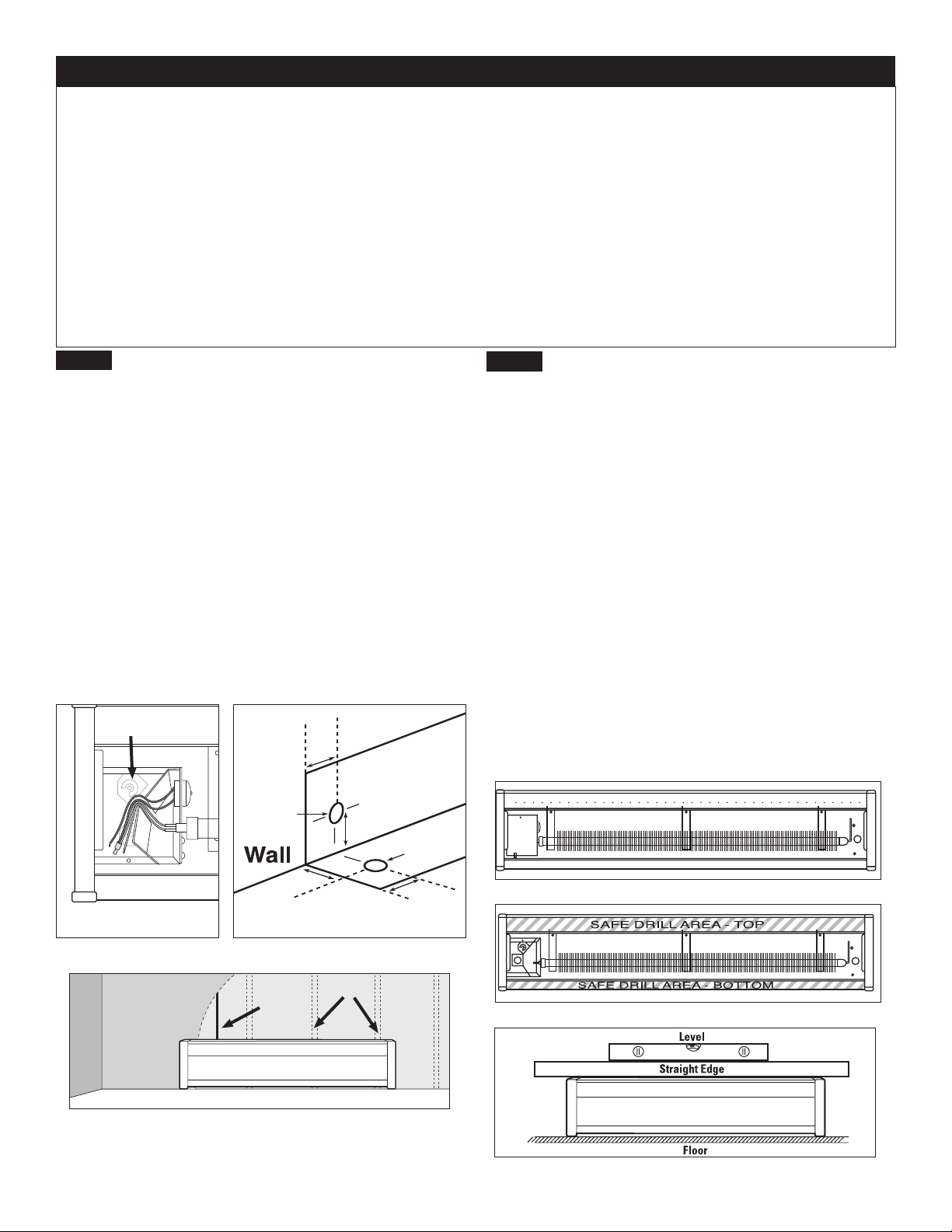
When wiring unit through rear, remove knockout and
place heater on wall. Mark knockout location on wall.
When wiring unit from oor, measure 1½ inches
(38mm) from wall and 2¼ inches (57mm) from left
end of unit. Cut a ⅞ inch (22mm) hole in oor cen-
tered on the measured location (See Figure 3).
Connect the grounding lead to the green grounding
screw (included), using a wire connector (not
included). (See Figure 2).
Protect electrical supply from kinks, sharp objects, oil,
grease, hot surfaces or chemicals.
Figure 6
Figure 2
2. Carefully remove front cover from heater by lifting
cover up from the bottom, and then outwards. Set
aside.
3. Remove wiring compartment cover, held by one
screw. (Figure 5).
4. Remove slotted knockout closest to the supply
wires and install a strain relief connector (not
included).
5. Pull supply wires through the strain relief connector
(not included) and secure, leaving 6 inch wire leads.
6. NOTE: If you plan to install a built-in EBKN
thermostat, you should do so now before mounting
your baseboard to the wall. See your EBKN
thermostat Owner’s Guide for instructions.
7. Position the heater and fasten one end of heater
to wall stud with screw (not included) in safe drill area
as shown in Figure 6. Before fastening to wall stud
at other end, place a level across top of heater and
make sure heater is level. (Figure 7).
8. After conrming heater is level, fasten other end of
heater to wall stud with screw (not included).
Figure 7
Figure 3
Page 3
Finished
Wall
Supply
Wire
Wall Studs
Floor
Grounding
Screw
Left end wiring shown
Drill areas; left end wiring shown
Checking with level
Left end wiring
(standard)
*Distance measured from
nished oor surface
Loading ...
Loading ...
Loading ...