6 720 813 635 (2022/01) US
Installation and Operating Instructions
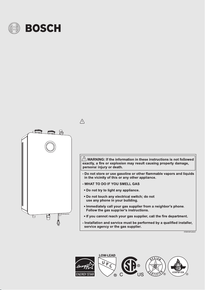
INDOOR RESIDENTIAL TANKLESS WATER HEATERS
Greentherm T9900 SE 160/199 | i 199
WARNING!
Improper installation, adjustment, alteration, service or maintenance can cause
injury or property damage. Refer to this manual. For assistance or additional infor-
mation consult a qualified installer, service agency or the gas supplier.
NOTICE
Upon completion of the installation, these instructions should be handed to the user
of the appliance for future reference.
160 000/199 000 Btu- Natural Gas | 160 000/199 000 Btu - Liquefied Petroleum
(LP) Gas

Table of contents
Greentherm T9900 SE/i – 6 720 813 635 (2022/01)
2
Table of contents
1 Key to symbols and safety instructions . . . . . . . . . . . . .3
1.1 Key to symbols . . . . . . . . . . . . . . . . . . . . . . . . . . . . . .3
1.2 Safety instructions. . . . . . . . . . . . . . . . . . . . . . . . . . .3
2 Safety information. . . . . . . . . . . . . . . . . . . . . . . . . . . . . . .8
3 Appliance details . . . . . . . . . . . . . . . . . . . . . . . . . . . . . . . .9
3.1 Features . . . . . . . . . . . . . . . . . . . . . . . . . . . . . . . . . . .9
3.2 Specifications (Technical data). . . . . . . . . . . . . . . 10
3.3 Unpacking the heater. . . . . . . . . . . . . . . . . . . . . . . 12
3.4 General rules to follow for safe operation. . . . . . . 13
3.5 Dimensions and minimum installation
clearances . . . . . . . . . . . . . . . . . . . . . . . . . . . . . . . 15
4 Installation instructions . . . . . . . . . . . . . . . . . . . . . . . . 16
4.1 Installation tools. . . . . . . . . . . . . . . . . . . . . . . . . . . 16
4.2 Introduction . . . . . . . . . . . . . . . . . . . . . . . . . . . . . . 16
4.3 Proper location for installing your heater . . . . . . . 16
4.4 Heater placement and clearances. . . . . . . . . . . . . 17
4.5 Hanging appliance on the wall. . . . . . . . . . . . . . . . 17
4.6 Venting . . . . . . . . . . . . . . . . . . . . . . . . . . . . . . . . . . 18
4.7 Factory settings . . . . . . . . . . . . . . . . . . . . . . . . . . . 33
4.7.1 Natural gas. . . . . . . . . . . . . . . . . . . . . . . . . . . . . . . 33
4.7.2 Liquid propane gas (after gas conversion) . . . . . 33
4.8 Gas piping & connections . . . . . . . . . . . . . . . . . . . 33
4.9 Water quality . . . . . . . . . . . . . . . . . . . . . . . . . . . . . 37
4.10 Water connections. . . . . . . . . . . . . . . . . . . . . . . . . 37
4.11 Domestic hot water recirculation . . . . . . . . . . . . . 39
4.12 Space heating applications . . . . . . . . . . . . . . . . . . 40
4.13 Measuring gas pressure. . . . . . . . . . . . . . . . . . . . . 44
5 Electrical connections. . . . . . . . . . . . . . . . . . . . . . . . . . 44
5.1 Electrical power supply . . . . . . . . . . . . . . . . . . . . . 44
5.2 Position of the fuses in control unit. . . . . . . . . . . . 45
6 Operation instructions . . . . . . . . . . . . . . . . . . . . . . . . . 45
6.1 For your safety read before operating your
water heater . . . . . . . . . . . . . . . . . . . . . . . . . . . . . . 46
6.2 Power . . . . . . . . . . . . . . . . . . . . . . . . . . . . . . . . . . . 46
6.3 Error code reset . . . . . . . . . . . . . . . . . . . . . . . . . . . 46
6.4 Temperature selection. . . . . . . . . . . . . . . . . . . . . . 46
6.4.1 Programming the default setpoint
temperature . . . . . . . . . . . . . . . . . . . . . . . . . . . . . . 47
6.5 Information /Adjustments menu. . . . . . . . . . . . . . 48
6.5.1 “P4” - Information . . . . . . . . . . . . . . . . . . . . . . . . . 48
6.5.2 SA - Settings . . . . . . . . . . . . . . . . . . . . . . . . . . . . . 48
6.5.3 AU - Technical Settings . . . . . . . . . . . . . . . . . . . . . 51
6.5.4 “P9” - Purge . . . . . . . . . . . . . . . . . . . . . . . . . . . . . . 51
6.6 Service menu - AU Technical Settings . . . . . . . . . 52
6.7 Water valves calibration . . . . . . . . . . . . . . . . . . . . 53
6.8 Gas type . . . . . . . . . . . . . . . . . . . . . . . . . . . . . . . . . 54
6.9 Wi-Fi connection . . . . . . . . . . . . . . . . . . . . . . . . . . 55
7 Maintenance and service . . . . . . . . . . . . . . . . . . . . . . . 58
7.1 Required annual maintenance . . . . . . . . . . . . . . . 58
7.2 Winterizing for seasonal use . . . . . . . . . . . . . . . . . 59
7.3 Mineral scale build-up . . . . . . . . . . . . . . . . . . . . . . 59
8 Troubleshooting. . . . . . . . . . . . . . . . . . . . . . . . . . . . . . . 60
8.1 Introduction . . . . . . . . . . . . . . . . . . . . . . . . . . . . . . 60
8.2 Burner does not ignite when a hot water
faucet is opened. . . . . . . . . . . . . . . . . . . . . . . . . . . 61
8.3 Water is too hot . . . . . . . . . . . . . . . . . . . . . . . . . . . 61
8.4 Water is not hot enough. . . . . . . . . . . . . . . . . . . . . 61
8.5 Low water flow/pressure. . . . . . . . . . . . . . . . . . . . 61
8.6 Hot water temperature fluctuates at faucet . . . . . 62
8.7 Noisy burner/heater during operation . . . . . . . . . 62
8.8 Error codes C1, C2, CF and/or CE . . . . . . . . . . . . 62
8.9 Error codes EA and/or EC . . . . . . . . . . . . . . . . . . . 62
8.10 Internal recirculation pump. . . . . . . . . . . . . . . . . . 62
8.11 Manifold gas pressure . . . . . . . . . . . . . . . . . . . . . . 63
8.12 Gas and Air Adjustment. . . . . . . . . . . . . . . . . . . . . 63
9 Problem solving . . . . . . . . . . . . . . . . . . . . . . . . . . . . . . . 68
10 Electrical diagram . . . . . . . . . . . . . . . . . . . . . . . . . . . . . 74
11 Sensor resistance charts . . . . . . . . . . . . . . . . . . . . . . . 76
12 Interior components diagram . . . . . . . . . . . . . . . . . . . 77
13 Protecting the environment. . . . . . . . . . . . . . . . . . . . . 78
14 Installer Checklist to be completed by installer
upon installation . . . . . . . . . . . . . . . . . . . . . . . . . . . . . . 78
15 List of used Open Source Components. . . . . . . . . . . . 80
16 FCC Regulatory notices . . . . . . . . . . . . . . . . . . . . . . . . 82
Key to symbols and safety instructions
3
Greentherm T9900 SE/i – 6 720 813 635 (2022/01)
1 Key to symbols and safety instructions
1.1 Key to symbols
Warnings
In warnings, signal words at the beginning of a warning are used
to indicate the type and seriousness of the ensuing risk if
measures for minimising danger are not taken.
The following signal words are defined and can be used in this
document:
DANGER:
DANGER indicates a hazardous situation which, if not avoided,
will result in death or serious injury.
WARNING:
WARNING indicates a hazardous situation which, if not
avoided, could result in death or serious injury.
CAUTION:
CAUTION indicates a hazardous situation which, if not avoided,
could result in minor or moderate injury.
NOTICE:
NOTICE is used to address practices not related to personal
injury.
Important information
The info symbol indicates important information where there is
no risk to people or property.
Additional symbols
Table 1
1.2 Safety instructions
H WARNING:
Before installation,
▶ Read all instructions. Perform the
steps in the indicated sequence.
▶ Have the water heater inspected by a
trained service technician at least
once every year.
▶ Failure to comply with these
instructions can result in severe,
possibly fatal, personal injury as well
as damage to property and
equipment.
H DANGER:
Installation and servicing.
Risk of fire when soldering and
brazing!
▶ Take appropriate protective measures
when soldering and brazing around
combustible and flammable material.
▶ Ensure that only a licensed contractor
installs or services the water heater.
▶ On hot components use only material
with adequate temperature stability.
H CAUTION:
▶ To ensure that the water heater
functions properly, follow these
installation and maintenance
instructions.
▶ Never close the blow-off line of the
pressure safety valve. For safety
reasons, water may escape during
heating.
Symbol Meaning
▶ a step in an action sequence
a reference to a related part in the document
•a list entry
– a list entry (second level)

Key to symbols and safety instructions
Greentherm T9900 SE/i – 6 720 813 635 (2022/01)
4
H DANGER:
Risk of explosion!
If you smell gas
▶ Turn off the gas shut-off valve.
▶ Open windows and doors.
▶ Do not try to light the appliance.
▶ Do not touch any electrical switch,
telephone, and do not use outlets.
▶ Extinguish all open flames. Do not
smoke! Do not use lighters!
▶ Warn all occupants of the building. Do
not ring doorbells!
▶ If you can hear gas leaking, leave the
building immediately.
▶ Prevent others from entering the
building and notify the police and fire
department from outside the
building.
▶ From outside the building, call the gas
utility company and a trained and
certified installer.
H DANGER:
If you smell flue gas inside the house
▶ Switch off the appliance.
▶ Open windows and doors.
▶ Inform the certified installer who
installed the appliance.
H DANGER:
Risk of poisoning!
Insufficient ventilation may cause
toxic flue gas to escape
▶ Never close off or reduce the size of
the air intake and outlet openings.
▶ The appliance must not be operated
until any obstructions have been
removed.
▶ Inform the customer of the problem
and the associated dangers.
H DANGER:
Danger from escaping flue gases.
▶ Ensure all vent pipes and chimneys
are not damaged or blocked.
▶ Connect only one appliance to each
vent system or chimney liner.
▶ The venting system piping must not
feed into another air extraction duct.
▶ Do not route the flue system piping
through or inside another air
extraction duct.
H DANGER:
Danger of explosion of flammable
gases
▶ Work on gas components may only be
carried out by a trained and certified
installer.
▶ Installation, gas and flue connection,
electrical connections and annual
maintenance must only be carried out
by a trained and certified installer.
H CAUTION:
Combustion air
▶ Keep the combustion air free of
corrosive substances (halogenated
hydrocarbons that contain chlorine or
fluorine compounds).

Key to symbols and safety instructions
5
Greentherm T9900 SE/i – 6 720 813 635 (2022/01)
H WARNING:
Never shut off safety valves!
▶ Water may escape from the safety
valve at any time when the water is
being heated.
H WARNING:
Inspection/maintenance
▶ Servicing and repairs may only be
carried out by a trained and certified
installer.
▶ Immediately correct all faults to
prevent system damage.
▶ Use only Bosch spare parts!
H CAUTION:
Instruct the customer
▶ Explain to the customer how the
appliance works and how to operate
it.
▶ Inform the customer that he/she must
not carry out any alterations or
repairs.
H DANGER:
Risk of electric shock!
▶ Ensure that only an authorized
contractor performs electrical work.
▶ Before performing electrical work,
disconnect the power and secure the
unit against unintentional
reconnection.
▶ Ensure the system has been
disconnected from the power supply.
H DANGER:
Risk of scalding at the hot water
fixture
▶ When the water heater is in operation,
temperatures in excess of 120 °F
(49 °C) can occur. To limit the
temperature at the faucet, install a
thermostatic DHW mixing valve.
▶ Water heated for washing the laundry,
dishes and for other cleaning
purposes can cause scalding and
permanent injuries.
▶ Children, disable and elderly are at
highest risk of being scalded. Never
leave such individuals in the tub or
shower unattended under any
circumstances. Children must not be
allowed to operate hot water faucets
themselves.
▶ If the building has occupants in the
above groups who operate hot water
faucets, or state laws / local
ordinances stipulate specific water
temperatures, take the following
precautions:
– Use the lowest possible
temperature setting.
– To prevent scalding, install a
tempering device, such as an
automatic mixing valve, at hot
water faucet or water heater. Select
and install the automatic mixing
valve in accordance with the valve
manufacturer's recommendations
and instructions.

Key to symbols and safety instructions
Greentherm T9900 SE/i – 6 720 813 635 (2022/01)
6
▶ Water exiting from drain valves can be
extremely hot. To avoid injuries:
– Check that all connections are
tight.
– Direct exiting water away from
people.
▶ Measures must be taken to protect
against excessive temperature and
pressure! Installation of a T&P safety
valve is required.
H WARNING:
Electrical safety
To protect against corrosion and ensure
compliance with the rules for electrical
safety, observe the following points:
▶ Use metal fittings for potable water
heating systems with plastic piping.
▶ Use only original accessories from the
manufacturer.
▶ When installation of the water heater
is complete, inspect and confirm
proper ground conductor.
H CAUTION:
Maintenance
▶ Inspect and maintain the water heater
on a yearly basis. Service as needed.
See chapter 7.1.
▶ Use only genuine spare parts.
H WARNING:
Flooding
▶ After a flood, do not use the appliance
if any part has been submerged.
Damage to appliances that have been
submerged can be quite severe and
pose numerous safety risks.
▶ Every appliance that has been
submerged must be replaced.
H WARNING:
Risk of explosion!
For your safety
▶ Do not store or use gasoline or other
flammable, combustible or corrosive
vapors and liquids in the vicinity of
this or any other appliance.
Key to symbols and safety instructions
7
Greentherm T9900 SE/i – 6 720 813 635 (2022/01)
DANGER:
Fatal accidents!
Carbon monoxide poisoning.
▶ Carefully plan where you install the heater. Correct
combustion air supply and flue pipe installation are very
important. If a gas appliance is not installed correctly, fatal
accidents can result such as carbon monoxide poisoning or
fire.
DANGER:
Carbon monoxide poisoning.
▶ Exhaust gas must be vented to outside using approved vent
material. See table 5, page 19 (In Canada use only
ULCS636 approved material). Vent and combustion air
connector piping must be sealed gas-tight to prevent flue
gas spillage, carbon monoxide emissions and risk of fire,
resulting in severe personal injury or death. Approved vent
terminations must be used.
DANGER:
Electric shock!
▶ Field wiring connections and electrical grounding must
comply with local codes, or in the absence of local codes,
with the latest edition of the National Electric Code, ANSI/
NFPA 70, or in Canada, all electrical wiring must comply
with the local codes and the Canadian Electrical Code, CSA
C22.1 Part 1.
DANGER:
Electric shock!
Shock hazard: line voltage is present.
▶ Before servicing the water heater, unplug power supply
cord from outlet. Failure to do so could result in severe
personal injury or death.
WARNING:
Damage to the appliance from over pressure.
▶ The heater must be disconnected from the gas supply
piping system during any pressure testing of that system at
test pressures equal to or more than 0.5 psi.
NOTICE:
▶ The appliance should be located in an area where leakage of
the heater or connections will not result in damage to the
area adjacent to the appliance or to lower floors of the
structure. When such locations cannot be avoided, it is
recommended that a suitable drain pan, adequately
drained, be installed under the appliance. The pan must not
restrict combustion air flow.
WARNING:
▶ The maximum inlet gas pressure must not exceed the value
specified by the manufacturer and the minimum value
listed is for the purpose of input adjustment.
NOTICE:
▶ If a water heater is installed in a closed water supply
system, such as one having a backflow preventer in the cold
water supply line, means shall be provided to control
thermal expansion. Contact the water supplier or local
plumbing inspector on how to control this situation.
WARNING:
Fire danger!
▶ Keep appliance area clear and free from combustible
materials, gasoline and other flammable vapors and
liquids.
WARNING:
Risk of CO poisoning!
▶ Do not obstruct the flow of combustion and ventilation air.
DANGER:
Risk of scalding and property damage.
▶ Precautions must be taken prior to manually operating the
relief valve to avoid contact with hot water discharged from
the relief valve and to prevent water damage.
Safety information
Greentherm T9900 SE/i – 6 720 813 635 (2022/01)
8
NOTICE:
Appliance damage!
▶ Label all wires prior to disconnection when servicing
controls. Wiring errors can result in improper and
dangerous operation. Verify proper operation after
servicing.
WARNING:
Relief valve discharges!
▶ If a relief valve discharges periodically, this may be due to
thermal expansion in a closed water supply system.
Contact the water supplier or local plumbing inspector on
how to correct this situation. Do not plug the relief valve.
WARNING:
Personal Injury from toxic chemicals.
▶ Toxic chemicals, such as those used for boiler treatment,
shall not be introduced into the potable water used for
space heating.
WARNING:
Personal Injury from toxic chemicals.
▶ A water heater which will be used to supply potable water
shall not be connected to any heating system or
component(s) previously used with a nonpotable water
heating appliance.
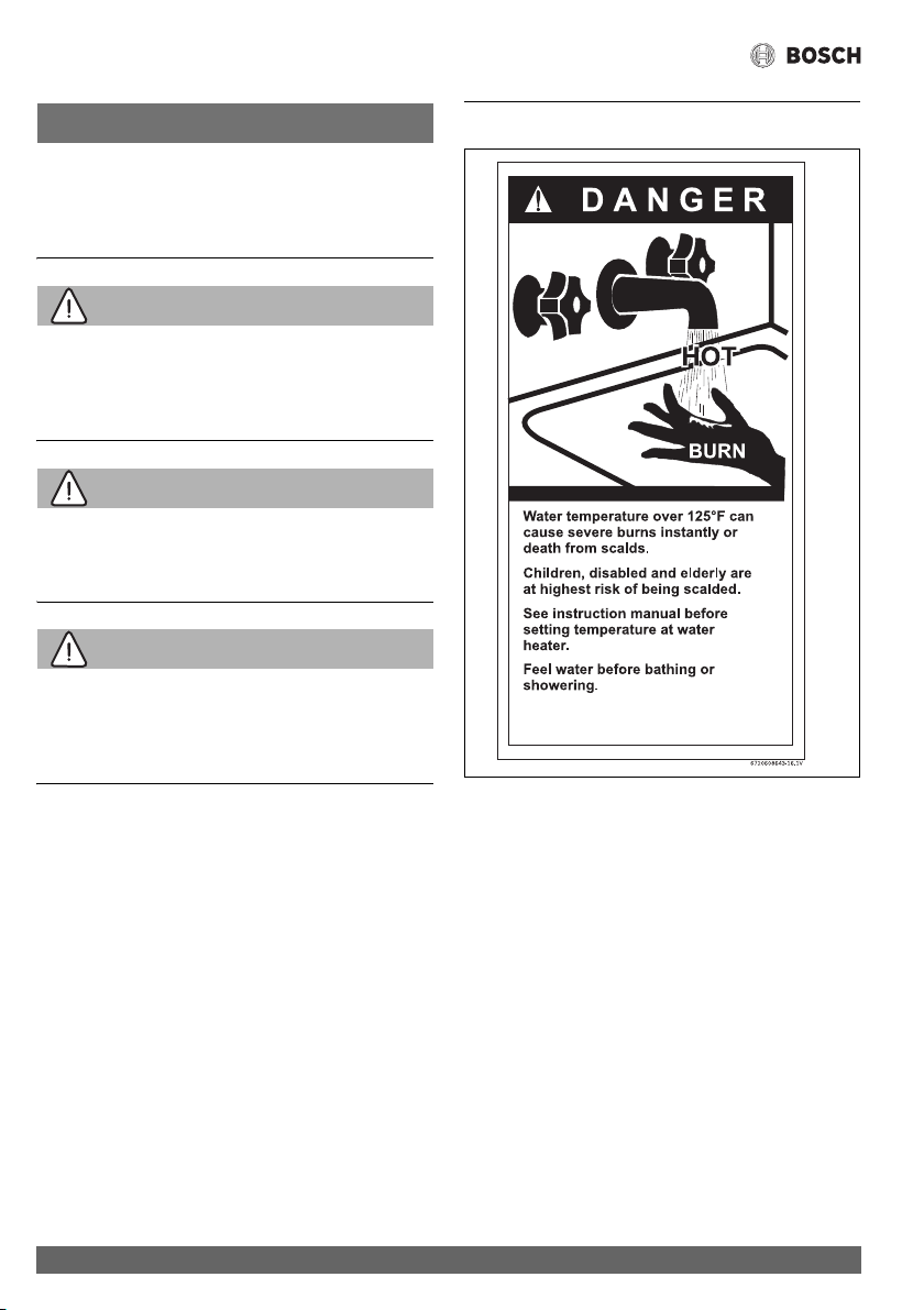
2 Safety information
Fig. 1
Appliance details
9
Greentherm T9900 SE/i – 6 720 813 635 (2022/01)
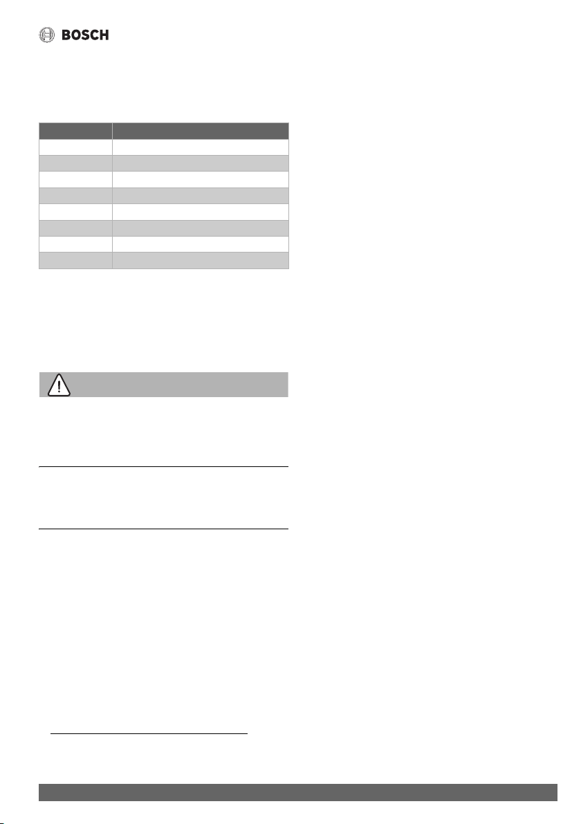
The chart below shows the relationship between water
temperature and time until there is a risk of scalding. It can be
used as the basis for determining the safest water temperature
for your application.
Table 2 Approximate time-temperature relationship until
there is a risk of scalding
WARNING:
This product can expose you to chemicals including lead, which
is known to the State of California to cause cancer and birth
defects or other reproductive harm. For more information go to
www.P65Warnings.ca.gov.
BOSCH water heater complies with the State of California Lead
Law (AB1953).
3 Appliance details
3.1 Features
Residential models
• Greentherm T9900 SE/i residential models
– maximum temperature 120 °F (49 °C)
1)
Parts
• Color Display with touch controls.
• High power segmented burner with low NOx
emissions.Modulating gas valve with pressure regulator.
•Modulating water valve.
• Active by pass water valve for quick response to changing
water flows.
• Burner power segmentation with modulation range from
1:22.
High quality materials for long working life
• Copper primary heat exchanger.
• Stainless Steel 316L condensing heat exchanger
Features
• Compact space saver: mounts on a wall with a supplied
bracket.
• Easily removable one-piece cover.
• On/Off and Temperature touch control.
• Reset function - Long press (> 3 sec.) the ON/OFF button.
• Programmable default temperature.
• Failure codes with message display for easy diagnostics
and repair.
• Real-time diagnostics for troubleshooting/informational
purposes.
• Built in freeze prevention.
• Recirculation pump.
• Integrated siphon to limit condensate freezing in external
condensate pipes.
The freeze prevention kit is designed to provide protection for
the water heater down to approximately -4 °F (-20 °C) for
short term conditions only. It will not protect the appliance in
areas where the temperature is routinely expected to be below
freezing.
Drain the water heater in the event of power outage in freezing
conditions.
Accessories (Bosch part #)
• Neutralizer Kit (7738001483)
• Wi-Fi module [802.11 b/g/n (2.4 GHz)] (7736504944)
• Aquastat kit (7736504584)
• Recirculation pump kit (7736504585)
• Tank loading NTC (7736504583)
• Wired remote control (7736504946)
• Wired remote control with Wi-Fi (7736504945)
• Cascading kit (7709003962)
Temperature Time to severe scalding
1)
1) Source: Moritz, A.R. and Henriques, F.C., Jr. (1947).
Studies of thermal injury. II. The relative importance of time
and surface temperature in the causation of cutaneous
burns, Am J of Pathol, 23, 695-720.
120 °F (49 °C) longer than 5 minutes
125 °F (51 °C) 1.5 to 2 minutes
130°F (54°C) approx.30seconds
135 °F (57 °C) approx. 10 seconds
140 °F (60 °C) less than 5 seconds
145 °F (62 °C) less than 3 seconds
150 °F (65 °C) approx. 1.5 seconds
155 °F (68 °C) approx. 1 second
1) Can be reprogrammed to achieve 140 °F (60 °C)
Appliance details
Greentherm T9900 SE/i – 6 720 813 635 (2022/01)
10
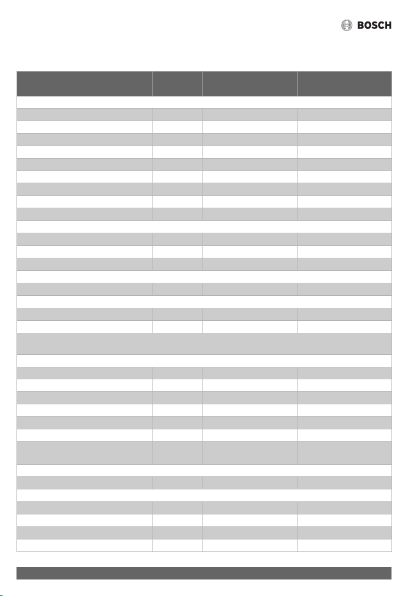
3.2 Specifications (Technical data)
Approved in US/Canada
Technical characteristics Units Greentherm T9900 SE/i Greentherm T9900 SE
199 000 Btu 160 000 Btu
Capacity
Maximum flow rate at a 35 °F (19.4 °C) rise
1)
GPM (l/min) 11.2 (42.4) 9 (34)
Maximum flow rate at a 45 °F (25 °C) rise GPM (l/min) 8.7 (32.9) 7(26.7)
Maximum flow rate at a 55 °F (30.6 °C) rise GPM (l/min) 7.2 (27.5) 5.8 (21.9)
Maximum flow rate at a 75 °F (41.7 °C) rise GPM (l/min) 5.2 (19.7) 4.2 (15.9)
Maximum flow rate at a 90 °F (50 °C) rise GPM (l/min) 4.4 (16.6) 3.5 (13.2)
Maximum output BTU/hr (kW) 197 010 (57.7) 157 608 (46.2)
Maximum input
2)
BTU/hr (kW) 199 000 (58.3) 160 000 (46.64)
Thermal efficiency (Efficiency in %) % > 99% > 99%
Minimum Input
3)
BTU/hr (kW) 9 000 (2.6) 9 000 (2.6)
Temperature Control
4)
Selection range °F ( °C) 100 - 120
5)
(38 - 49) 100 - 120
5)
(38 - 49)
Default temperature °F ( °C) 120 (49) 120 (49)
Stability
6)
°F ( °C) ±2 (±1) ±2 (±1)
Gas Requirement
Gas connection inches ¾" ¾"
Peak load inlet gas pressure
7)
Propane water column 8" - 13" 8" - 13"
Natural Gas water column 3.5" - 10.5" 3.5" - 10.5"
To assure maximum heat input at maximum vent length minimum gas pressure should be 5" W.C.(199kBtu) and 4" W.C.
(160kBtu). For more information see section 4.6.3.
Water
Top hot water connection NPT inches ¾" ¾"
Top cold water connection NPT inches ¾" ¾"
Minimum water flow
8)
GPM (l/min) 0.45 (1,7) 0.45 (1,7)
Maximum water pressure PSI (bar) 150 (10,3) 150 (10,3)
Minimum water pressure PSI (bar) 18 (1,2) 18 (1,2)
Minimum well pressure PSI (bar) 30 (2,1) 30 (2,1)
Water valve material Polymer (PPS) (Polypropylene
Sulfide)
Polymer (PPS) (Polypropylene
Sulfide)
Combustion
CO level ppm ≤ 250 (measured) ≤ 250 (measured)
Dimensions
Depth inches (mm) 9
27
/
32
(250) 9
27
/
32
(250)
Width inches (mm) 18
19
/
32
(471,5) 18
19
/
32
(471,5)
Height inches (mm) 31½ (800) 31½ (800)
Net weight pounds (kg) 78.70 (35.7) / 81.13 (36.8) 74.3 (33.7)

Appliance details
11
Greentherm T9900 SE/i – 6 720 813 635 (2022/01)
Table 3
Safety devices
• Flame failure device (flame detection via ionization rod)
•Overheat prevention
• Inlet water temperature sensor
• Outlet water temperature sensor
• Exhaust flue gas temperature sensor
•Water flow sensor
• Air flow sensing technology (Optiflow)
• Scaling detection sensor (HE flue gas temperature sensor)
Gross weight pounds (kg) 91.05 (41.3) / 93.48 (42.4) 86.64 (39.3)
Electrical
Nominal V AC 120 120
Frequency Hz 60 60
Amperage (Idle) mA 40 40
Operation A ≤ 2,7 ≤ 2,7
Water protection
9)
IP X4D X4D
1) These flow rates are based upon setting the unit to higher temperatures and then mixing down using cold water after the unit.
2) Input rating is based on sea level operation and need not be changed for operation up to 2000 ft (610 m) elevation. For
operation at elevations above 2000 ft (610 m), input rating is automatically reduced at the rate of 4 percent for each 1000 ft
(305 m) above sea level.
3) When converted to LPG the minimum input is 17 000 BTU/hr (5 kW).
4) with constant flow
5) Can be reprogrammed to achieve 140 °F (60 °C) (see chapter 6.4).
6) Requirements: Steady flows, single unit installations, up to 140 °F (60 °C).
7) To measure Gas Pressure, see Measuring Gas Pressure, chapter 4.13, page 44.
8) Refers to activation point. Deactivation point value is 0.35GPM (1.3 l/min).
9) Protection against water spray.
Technical characteristics Units Greentherm T9900 SE/i Greentherm T9900 SE
199 000 Btu 160 000 Btu
Appliance details
Greentherm T9900 SE/i – 6 720 813 635 (2022/01)
12
3.3 Unpacking the heater
The heater is default-set by the manufacturer to operate with
Natural Gas, for use with Liquid Propane, follow the conversion
instructions in section 6.8.1. Before starting up the heater
for the first time, be certain you have the heater correctly
set for your type of Gas - Propane or Natural Gas.
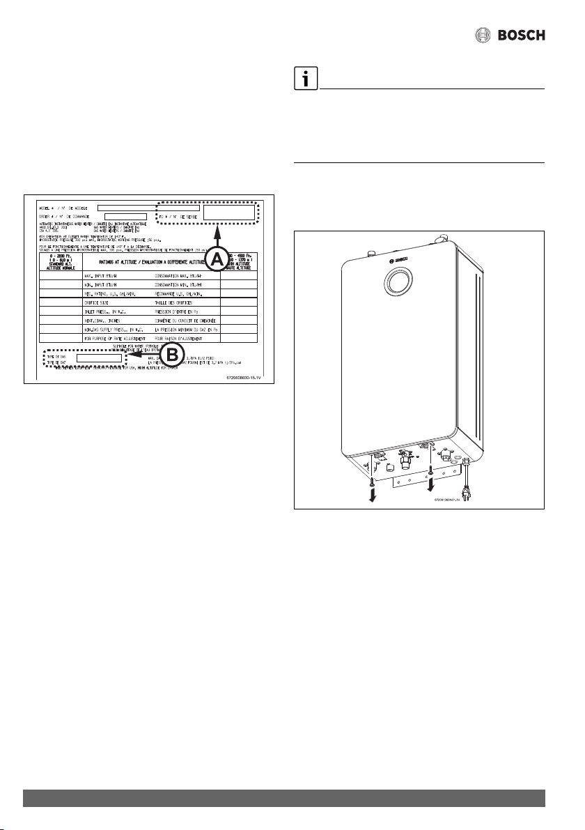
Identification labels are found on the shipping box, and on the
rating plate which is located on the left side (when facing
appliance front) of the cover.
Fig. 2 Rating plate
[1] Serial number
[2] Type of gas (Natural gas by default)
3.3.1 The box includes
• Water Heater
•LP Conversion Kit
•Pressure relief valve
• Bracket and screws for wall hanging the heater
• Installation manual (manual can be downloaded at
www.boschheatingandcooling.com)
The Greentherm T9900 SE/i are not approved or designed
for:
• Manufactured (mobile) homes, boats or any mobile
installation. (Modular homes are acceptable for
installation).
• Use above 8000 ft A.S.L. altitude.
• Applications where inlet water temperature is higher
than 140 °F (60 °C) for Residential appliances.
In these applications a 3 way valve or thermostatic
mixing valve must be installed.
• Use with commercial dishwasher pre rinse spray valves.
• Booster applications.
In preheated inlet water applications (i.e. solar preheat),
activation flow rate will vary depending upon the unit set point,
inlet water temperature and the demand flow rate thru the unit.
Please consult Bosch for further details to determine if this will
function in your application.
3.3.2 Remove front cover
▶ Loosen two Phillips head screws located on the bottom of
the front cover (fig. 3).
Fig. 3 Loosen two Phillips head screws
Appliance details
13
Greentherm T9900 SE/i – 6 720 813 635 (2022/01)
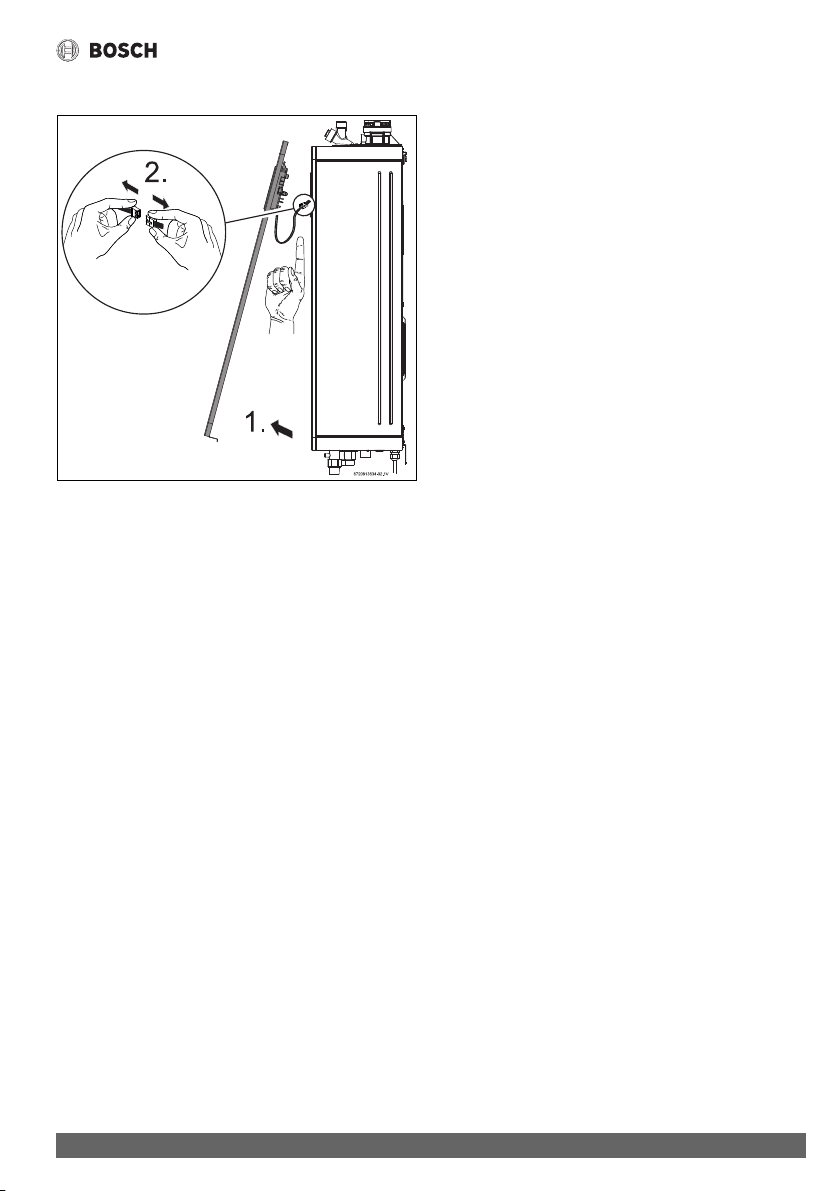
▶ Slowly open the front cover [1].
Fig. 4 Open front cover
▶ Disconnect the wire from the HMI (display) [2].
▶ Lift the front cover to remove from the appliance.
▶ Install the appliance so that it hangs vertically.
3.4 General rules to follow for safe operation
H Warning: Safety Rules!
1. You must follow these instructions
when you install your heater. In the
United States: The installation must
conform with local codes or, in the
absence of local codes, the National
Fuel Gas Code ANSI Z223.1/NFPA
54.
In Canada: The Installation must
conform with CSA B149.(1,2)
INSTALLATION CODES and /or local
installation codes.
2. Carefully plan where you install the
heater. Correct combustion air supply
and vent pipe installation are very
important. If not installed correctly,
fatal accidents can occur, such as
carbon monoxide poisoning or fire.
3. When the unit is installed indoors with
DIRECT VENT (exhaust vent and air
intake connected to the outside) it is
permitted to be located in bathrooms,
bedrooms and occupied rooms that
are normally kept closed. See
chapter 4.6 (page 18). If the unit will
be installed indoors and use indoor
combustion air (NON-DIRECT VENT),
the place where you install the heater
must have enough ventilation. The
National Fuel Gas Codes do not
allow NON-DIRECT VENT gas fired
water heater installations in
bathrooms, bedrooms or any
occupied rooms normally kept
closed. See chapter 4.6 (page 18).
4. You must correctly vent your heater.
See chapter 4.6 (page 18) on
VENTING.
5. The appliance and its gas connection
must be leak tested before placing the
appliance in operation.
The appliance must be isolated from
the gas supply piping system by
closing its individual manual gas
shutoff valve (not supplied with
heater) during any pressure testing at
pressures in excess of ½ Psig (3.5
kPa).

Appliance details
Greentherm T9900 SE/i – 6 720 813 635 (2022/01)
14
6. Keep the water heater area clear and
free from combustibles and
flammable liquids. Do not locate the
heater over any material which might
burn.
7. Correct gas pressure is critical for the
proper operation of this heater. Gas
piping must be sized to provide the
required pressure at the maximum
output of the heater, while all the
other gas appliances are in operation.
Check with your local gas supplier,
and see the section on connecting the
gas supply. See chapter 4.8
(page 33).
8. Should overheating occur or the gas
supply fail to shut off, turn off the gas
supply at the manual gas shut off
valve, on the gas line. Note: manual
gas shutoff valve is not supplied with
the heater but must be field installed.
9. Do not use this appliance if any part
has been underwater. Immediately
call the responsible party for the
installation of your appliance to
inspect the appliance and to replace
any part of the water heater which has
been underwater.
10.Failure to install the heater correctly
may lead to unsafe operation.
Appliance details
15
Greentherm T9900 SE/i – 6 720 813 635 (2022/01)
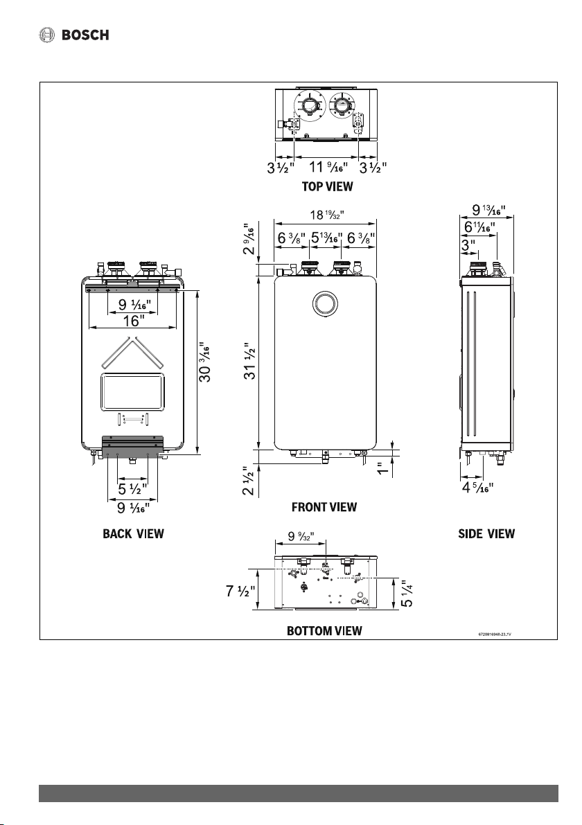
3.5 Dimensions and minimum installation clearances
Fig. 5 Dimensions
Installation instructions
Greentherm T9900 SE/i – 6 720 813 635 (2022/01)
16
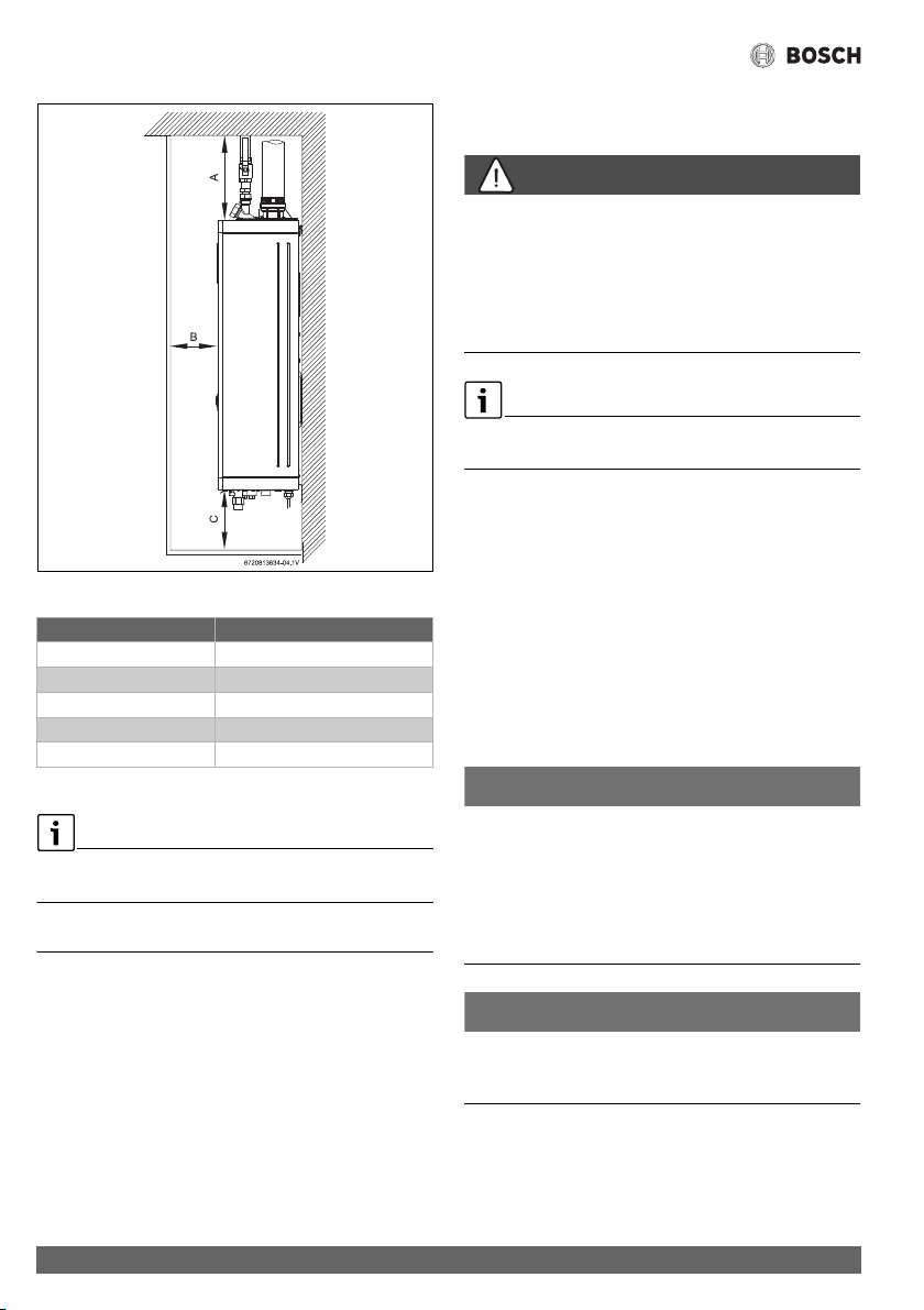
Fig. 6 Side view
Table 4 Required minimum clearances for combustibles
For servicing access, a 2ft clearance is recommended to the
front cover.
4 Installation instructions
4.1 Installation tools
The following specialized tools may be required if converting
from natural gas to LP:
• Pressure manometer
4.2 Introduction
Please follow these instructions. Failure to follow
instructions may result in:
▶ Damage or injury.
▶Improper operation.
▶ Loss of warranty.
DANGER:
▶ The water heater must be installed by a qualified installer in
accordance with these instructions. If improperly installed,
a hazardous condition such as explosion or carbon
monoxide poisoning could result. Bosch
Thermotechnology Corp. is not responsible for improperly
installed appliances.
Common installation practice is to first determine the path and
method of venting, then design the piping layout.
4.3 Proper location for installing your heater
Carefully select the location of the water heater. For your safety
and for proper heater operation, you must provide combustion
air to the heater and properly vent the exhaust gases.
Follow the guidelines below:
▶ 1. Locate the heater where venting, gas and plumbing
connections are feasible and convenient.
▶ 2. The hot water lines should be kept short and insulated to
save energy. It is recommended to locate the water heater
as close as practical to the most frequently used hot water
fixtures.
NOTICE:
Risk of appliance freezing!
▶ The water in this water heater is cold and always remains
cold except for the times the burner is on. In the event of
power outage in conjunction with freezing temperatures,
the heater should be drained.
See chapter 7.2, page 59 “Winterizing” for draining
instructions.
NOTICE:
Installation
▶ Do not install the water heater in rooms with a high
moisture level (e.g. bathrooms, saunas).
Greentherm T9900 SE/i
TOP (A) 12"
FRONT (B) 1"
BACK 0"
SIDES 1"
FLOOR (C) 12"
Installation instructions
17
Greentherm T9900 SE/i – 6 720 813 635 (2022/01)
WARNING:
▶ Flammable materials, gasoline, pressurized containers, or
any other items or articles that are potential fire hazards
must NOT be placed on or adjacent to the heater. The
appliance area must be kept free of all combustible
materials, gasoline and other flammable vapors and
liquids.
WARNING:
Risk of blockage!
▶ Excess of solid particles (e.g. bugs, pollen) in the air intake
may clog the air filter and lead to premature failure of the
heater if not protected accordingly.
▶ Do not install the water heater in areas where excess of
solid particles may accumulate.
NOTICE:
Risk of blockage!
▶ Optional paper filter (part # 8738725270) can be
installed on the air fan for increased protection against
dusty, dirty combustion air or heavy pollen entering the
combustion chamber to reduce the risk of burner blockage.
▶ In areas with high solid particles content in the air it is
recommended to use this filter. Maintenance frequency
might need to be adjusted to keep the filter clean and allow
a good performance of the heater.
4.4 Heater placement and clearances
The water heater design is approved for installation on a
combustible wall (see chapter 4.5 Mounting installation)
provided the floor covering below the heater is
noncombustible.
For installations in an alcove or closet, maintain the minimum
clearances to combustible and non-combustible materials. See
fig. 6, page 16.
4.5 Hanging appliance on the wall
WARNING:
Severe personal injury and property damage!
Before mounting appliance:
▶ Check that there are no loose or damaged parts inside the
appliance.
▶ Set the heater gas type according to the gas supplied to the
unit.
▶ Confirm that the water heater has been properly setup for
the gas type supplied to the unit. See conversion
instructions in section 6.8.1 as needed.
Front cover should be removed (see instructions on page 12) in
order to inspect components visually.
WARNING:
▶ Do not install this appliance on a carpeted wall. The heater
must be mounted on a wall using appropriate anchoring
materials.
NOTICE:
Risk of appliance freezing!
▶ In areas where outside temperature is routinely below 32°F
(0 °C) and the heater is to be installed on the inside of an
exterior wall, provide a minimum 2" air gap or rigid
insulation between the heater back and the wall.
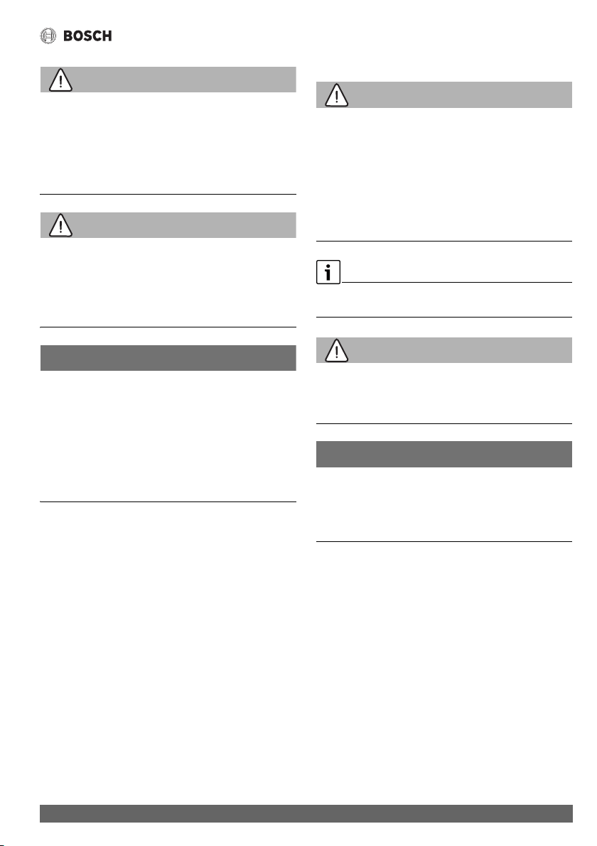
If the wall is sheathed with plaster or drywall, it is
recommended that two support boards, either 1"x 4" or 1/2"
(minimum) plywood first be attached across a pair of studs, see
fig. 7.
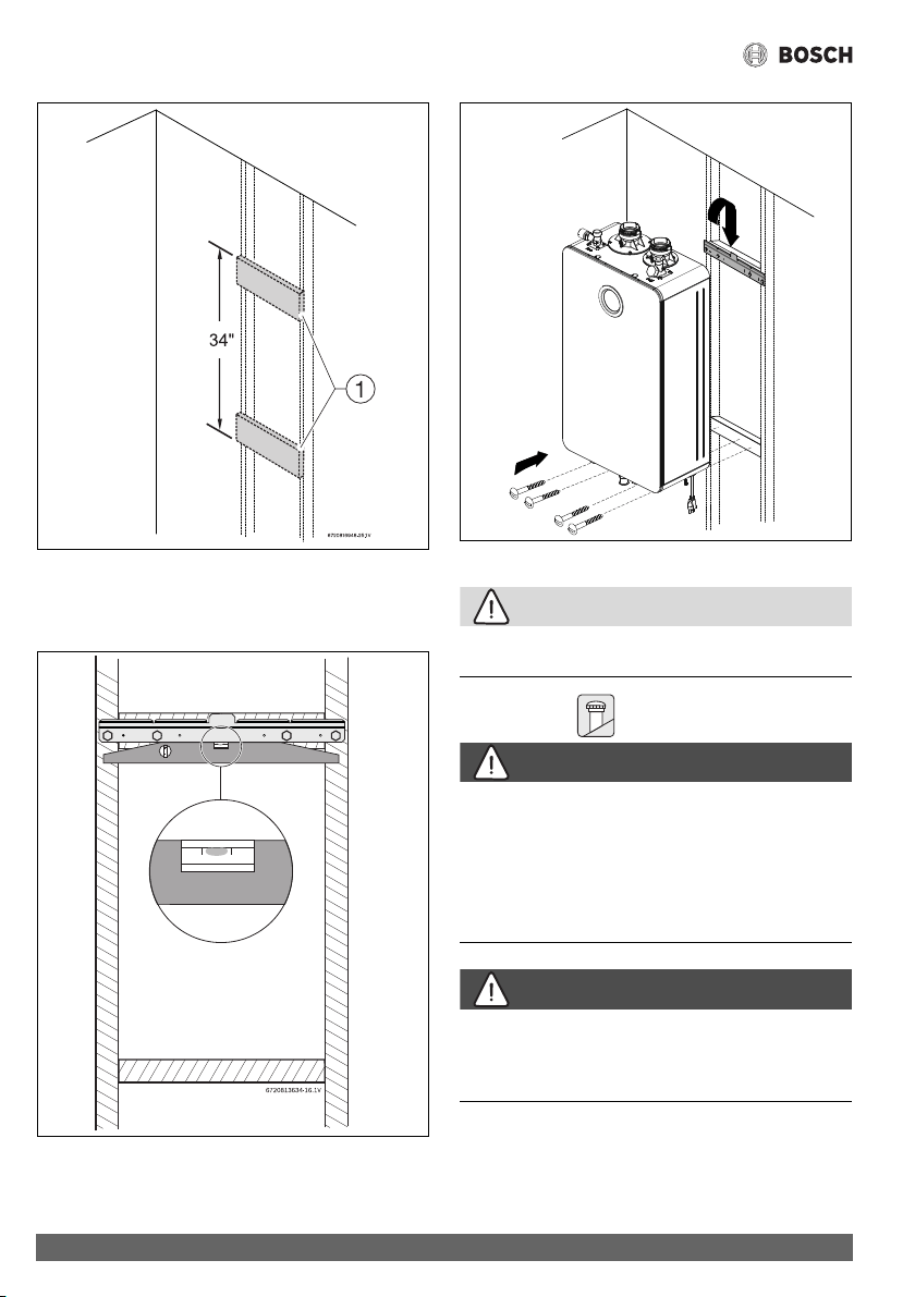
▶ Secure the wall mounting bracket provided with the heater
to a wall surface. The heater must be kept level on the wall
surface, see fig. 8, page 18.
▶ Hang the appliance on the bracket, see fig. 9, page 18.
Installation instructions
Greentherm T9900 SE/i – 6 720 813 635 (2022/01)
18
Fig. 7 Distance between support boards
[1] Support boards
Vertical studs are typically 16" (406mm) on center.
Fig. 8 Leveling wall mounting bracket
Fig. 9 Mounting the heater
CAUTION:
Personal injury and property damage.
▶ Appliance must be installed vertically.
4.6 Venting
DANGER:
Flue gas poisoning!
▶ Do not reduce the exhaust or combustion air vent pipe
sizes.
▶ Do not common vent with any other vented appliance or
stove.
▶ Do not use Type-B vent as the actual exhaust vent system
for the appliance.
DANGER:
Flue gas poisoning!
▶ Failure to vent the exhaust gases to the outside (see table 5
for proper material) may result in dangerous flue gases
filling the structure in which it is installed.
6720813634-28.1V
1.
2.
Installation instructions
19
Greentherm T9900 SE/i – 6 720 813 635 (2022/01)
NOTICE:
▶ Installations resulting in negative pressure/back draft
require sealed combustion (twin pipe / concentric).
Damage caused from back draft, ie. freezing, are not
covered by warranty.
NOTICE:
Appliance malfunction!
▶ Protect the inlet air supply from leaves and debris by
installing a screen on the intake of the termination. A
minimum screen mesh size of ¼" is recommended.
▶ Do not install the water heater in areas where dust and
chemicals like hair sprays, spray detergents, chlorine, may
accumulate.
Do not cover non-metallic vent pipe and fittings with thermal
insulation, unless going through an insulated wall or ceiling.
Flue temperature:
▶ To prevent the risk of flue material overheat the appliance's
flue temperature is sensed and is limited. The flue
temperature limit is dependent on inlet water temperature.
▶ Residential models: Maximum flue temperature is limited
to 145°F (63°C).
4.6.1 Vent options
This appliance can be installed as direct vent or Category IV.
The Greentherm T9900 SE/i is approved with the following
venting options:
Table 5 Approved vent materials
For specific questions concerning vent material,
specifications, usage or installation, please contact the
vent manufacturer directly.
Approved Vent Manufacturers;
•M&G
•Centrotherm
•IPEX
• Royal Plastics
•Eccovent
•Charlotte
•Z-Flex
Do not use cellular foam core pipe for exhaust.This material is
approved for intake only.
The vent connection for the appliance is secured with a clamp
on the appliance exhaust adapter. All other vent connections
must be glued, except PP and flex PP. Slide the vent pipe into
the exhaust adapter. The exhaust pipe must be properly
supported and must be pitched a minimum of a ¼ inch per foot
back to the appliance. This allows the condensate to drain
properly.
Item Material United States Canada
Vent or air intake pipe
and fitting
PP
flexible M&G /
DuraventCentrotherm
(UL-1738)
Thermoplastic vent pipe
must be certified to ULC
S636.
Air Intake pipe may be of any
material listed (left)
concentric
rigid
PVC schedule 40 ANSI/ASTM D1785
PVC-DWV ANSI/ASTM D2665
CPVC schedule 40 ANSI/ASTM F441
ABS-DWV schedule 40 ANSI/ASTM D2661
Pipe cement / primer PVC ANSI/ASTM D2564
CPVC ANSI/ASTM F493
ABS ANSI/ASTM D2235
Installation instructions
Greentherm T9900 SE/i – 6 720 813 635 (2022/01)
20
Maximum vent lengths and equivalent lengths per table 8
apply.
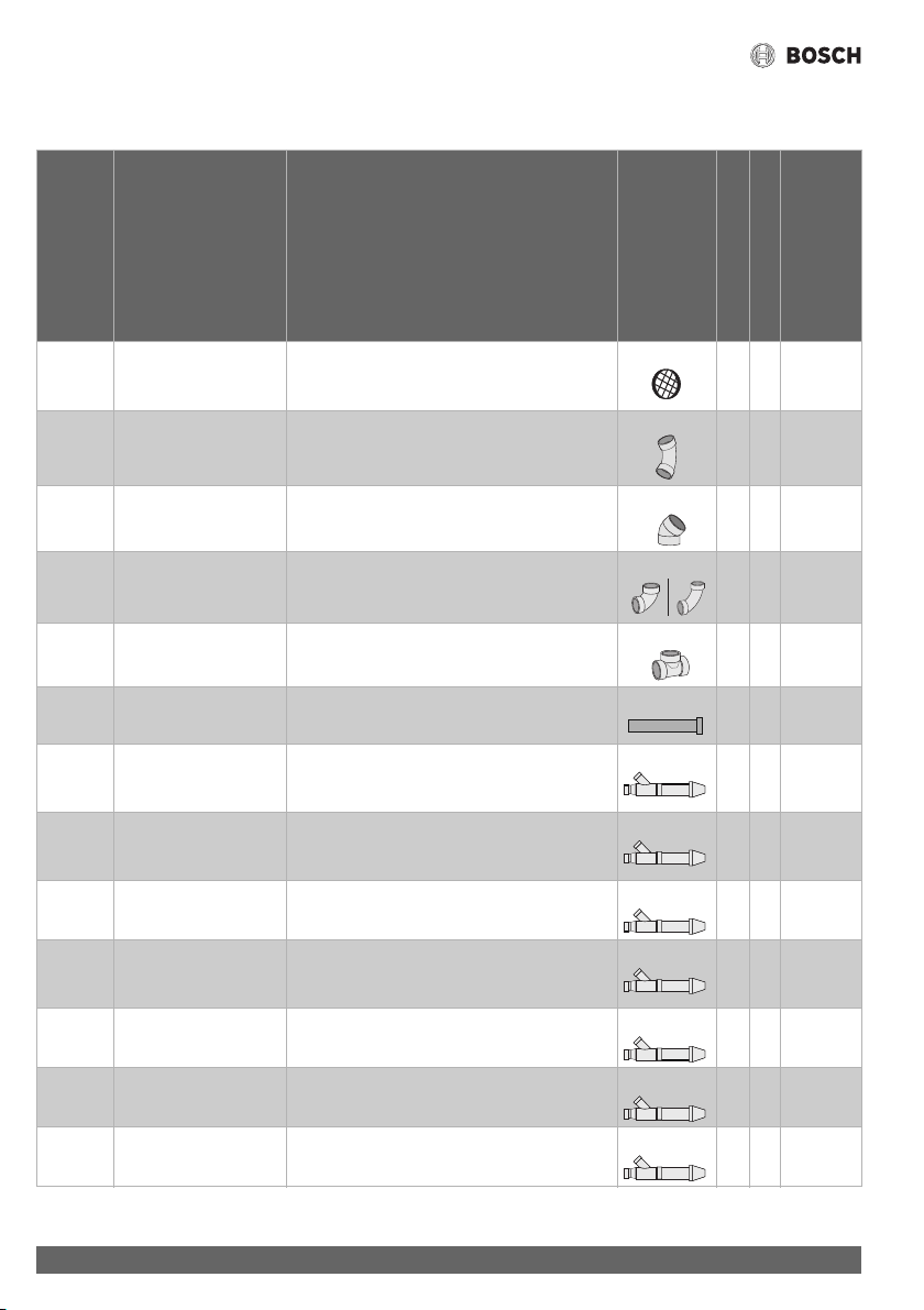
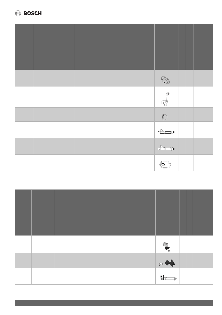
4.6.2 Approved vent components and terminations
Manufacturer
Manufacturer part number
Product description
Diagram
Horizontal
Vertical
Equivalent Lengths (Ft.)
Bosch 196050
196051
196052
2" Bird screen
3" Bird screen
4" Bird screen
hh2
- - 2", 3", and 4" SCH40 (Solid Core) PVC/CPVC
45° long sweep elbow
h h 2.5
- - 2", 3", and 4" SCH40 (Solid Core) PVC/CPVC
45° short sweep elbow
hh2.5
- - 2", 3", and 4" SCH40 (Solid Core) PVC/CPVC
90 ° short/long/extra long sweep elbow
1)
h h 5
- - 2", 3", and 4" SCH 40 (Solid Core) PVC/CPVC
"T" terminal w/vent screen
hh10
- - 2", 3" and 4" SCH40 (Solid Core) PVC/CPVC
straight pipe
h h 1
IPEX 196005 PVC Concentric termination (2" by 16" long) hhExhaust:
1.5
Intake: 20
IPEX 196105 PVC Concentric termination (2" by 28" long) h h Exhaust:
2.5
Intake: 20
IPEX 196125 PVC Concentric Termination Kit (2" by 40" long) hhExhaust: 3
Intake: 20
IPEX 196006 / 197009 PVC / CPVC Concentric Termination Kit
(3" by 20" long)
h h Exhaust:
1.5
Intake: 40
IPEX 196106 / 197107 PVC / CPVC Concentric Termination Kit
(3" by 32" long)
hhExhaust: 2
Intake: 40
IPEX 196116 / 197117 PVC / CPVC Concentric Termination Kit
(3" by 34" long)
h h Exhaust: 2
Intake: 40
IPEX 196021 / 197021 PVC / CPVC Concentric Termination Kit
(4" by 36" long)
hhExhaust: 2
Intake: 60
Installation instructions
21
Greentherm T9900 SE/i – 6 720 813 635 (2022/01)
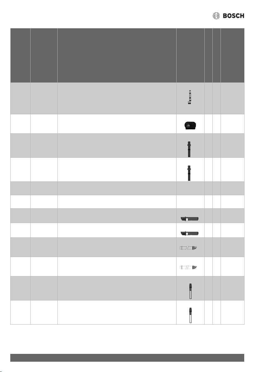
Table 6 Approved PVC/CPVC Vent Components & Terminations
IPEX 196984
196985
196986
2" PVC Low profile termination kit
3" PVC Low profile termination kit
4" PVC Low profile termination kit
h Exhaust: 0
Intake: 5
IPEX 081216
081219
2" PVC Wall Termination Kit
3" PVC Wall Termination Kit
h Exhaust:
15
Intake: 7.5
Temple
industries
ECAP 321 2" PVC termination E-Cap
3" PVC termination E-Cap
h 2
4
Royal
Plumbing
Solutions
52CVKGVS6502 2" GVS-65 Concentric Vent Termination Kit hhExhaust: 2
Intake: 20
Royal
Plumbing
Solutions
52CVKGVS6503 3" GVS-65 Concentric Vent Termination Kit h h Exhaust: 2
Intake: 40
Royal
Plumbing
Solutions
52SWVKGVS6502
52SWVKGVS6503
2" GVS-65 Side Wall Vent Termination Kit
3" GVS-65 Side Wall Vent Termination Kit
h Exhaust: 0
Intake: 5
1) Close sweep fittings are not accepted.
Manufacturer
Manufacturer part number
Product description
Diagram
Horizontal
Vertical
Equivalent Lengths (Ft.)
Duravent
M&G
810009685
810009713
810009745
2" PP Twin pipe termination
3" PP Twin pipe termination
4" PP Twin pipe termination
h Exhaust: 2
Intake: 2
Duravent
M&G
810009684
810009712
2" PP Single Horizontal Termination
3" PP Single Horizontal Termination
h 6
Duravent
M&G
810009682
810009710
(2" x 4") PP Horizontal Termination Kit - Concentric
(3" x 5") PP Horizontal Termination Kit - Concentric
h Exhaust:
20
Intake: 40
Manufacturer
Manufacturer part number
Product description
Diagram
Horizontal
Vertical
Equivalent Lengths (Ft.)
Installation instructions
Greentherm T9900 SE/i – 6 720 813 635 (2022/01)
22
Table 7 Approved PP Vent Components & Terminations
Duravent
M&G
810009692
810009720
810009693
810009721
(2" x 4") Black PP Vertical Termination Kit - Concentric
(3" x 5") Black PP Vertical Termination Kit - Concentric
(2" x 4") Terra-Cotta PP Vertical Termination Kit - Concentric
(3" x 5") Terra-Cotta PP Vertical Termination Kit - Concentric
h Exhaust:
20
Intake: 40
Centro-
therm
ISLPT0202
ISLPT0303
2" Low profile Wall Termination
3" Low profile Wall Termination
h Exhaust: 0
Intake: 5
Centro-
therm
ICRT2439 2" x 4" Concentric Roof Termination h Exhaust: 5
Intake: 5
Centro-
therm
ICRT3539 3" x 5" Concentric Roof Termination h Exhaust:
10
Intake: 10
Centro-
therm
ICTCR24 2" x 4" (60/100mm) Exhaust:
Intake:
Centro-
therm
ICCT3503 3" x 5" (80/125mm) Exhaust:
Intake:
Centro-
therm
ICWT242 2" x 4" Concentric Wall Termination h Exhaust: 4
Intake: 4
Centro-
therm
ICWT352 3" x 5" Concentric Wall Termination h Exhaust: 6
Intake: 6
Ecco
Manu-
facturing
190288 2" PP Concentric Terminations Horizontal (Wall) Terminations h Exhaust: 4
Intake: 4
Ecco
Manu-
facturing
190388 3" PP Concentric Terminations Horizontal (Wall) Terminations h Exhaust: 6
Intake: 6
Ecco
Manufact
uring
190295 2" PP Vertical (Roof) Terminations h Exhaust: 4
Intake: 4
Ecco
Manufact
uring
190395 3" PP Vertical (Roof) Terminations h Exhaust: 8
Intake: 8
Manufacturer
Manufacturer part number
Product description
Diagram
Horizontal
Vertical
Equivalent Lengths (Ft.)
Installation instructions
23
Greentherm T9900 SE/i – 6 720 813 635 (2022/01)
4.6.3 Vent specifications
CAUTION:
Risk of CO poisoning!
An improperly sized venting system may lead to undesired
effects such as the formation of condensate, gas leakage or
spillage.
Establish vent clearances that comply with the vent
manufacturer's specifications and all applicable national/local
codes.
Minimum combustion air and exhaust pipe length
The minimum exhaust pipe length is 1 foot (0.3m) of straight
vent pipe. The minimum combustion air pipe length is one 1 ft
pipe or one 90° elbow with an air intake grill cap to prevent
debris from falling into the appliance.
Maximum combustion air and exhaust pipe length
The table 8 displays the maximum allowable straight pipe
lengths for air intake and exhaust piping. Reduce the maximum
allowable pipe length by the equivalent lengths for each elbow
used and termination used.
PROPER GAS PRESSURE!
The following section assumes the water heater will receive gas
pressure greater than or equal to 5" WC for the 199kBTU
models (4" WC for 160kBTU models). In cases of gas pressure
below 5" WC for the 199kBTU (4" WC for the 160kBTU models)
the maximum heat input is reduced.
The values of maximum flue length in table 8 are before any
deductions for elbows or terminations.
Table 8 Maximum Allowable Exhaust and Air intake Lengths
Improper gas pressure or vent length may result in undesired
symptoms or errors such as noisy burner, C1, C2, CF, EA, EC.
The vent for this appliance shall not terminate:
1. over public walkways; or
2. near soffit vents or crawl space vents or other areas where
condensate or vapor could create a nuisance or hazard or
cause papery damage; or
3. where condensate vapor could cause damage or could be
detrimental to the operation of regulators, relief valves, or
other equipment.
Venting Max equivalent
Exhaust length
1)
Max equivalent
Intake length
1)
2" Twin pipe 60ft
2)
60ft
3" Twin pipe 280ft
2)
280ft
2"/ 4"
Concentric pipe
60ft
2)
3"/ 5"
Concentric pipe
280ft
2)
1) Do not exceed the maximum length allowance for either
pipe by combining them.
2) To assure maximum heat input at maximum vent length
minimum gas pressure should be 5" W.C. for the 199 kBTU
models and 4" W.C. for the 160 kBTU models.
Installation instructions
Greentherm T9900 SE/i – 6 720 813 635 (2022/01)
24
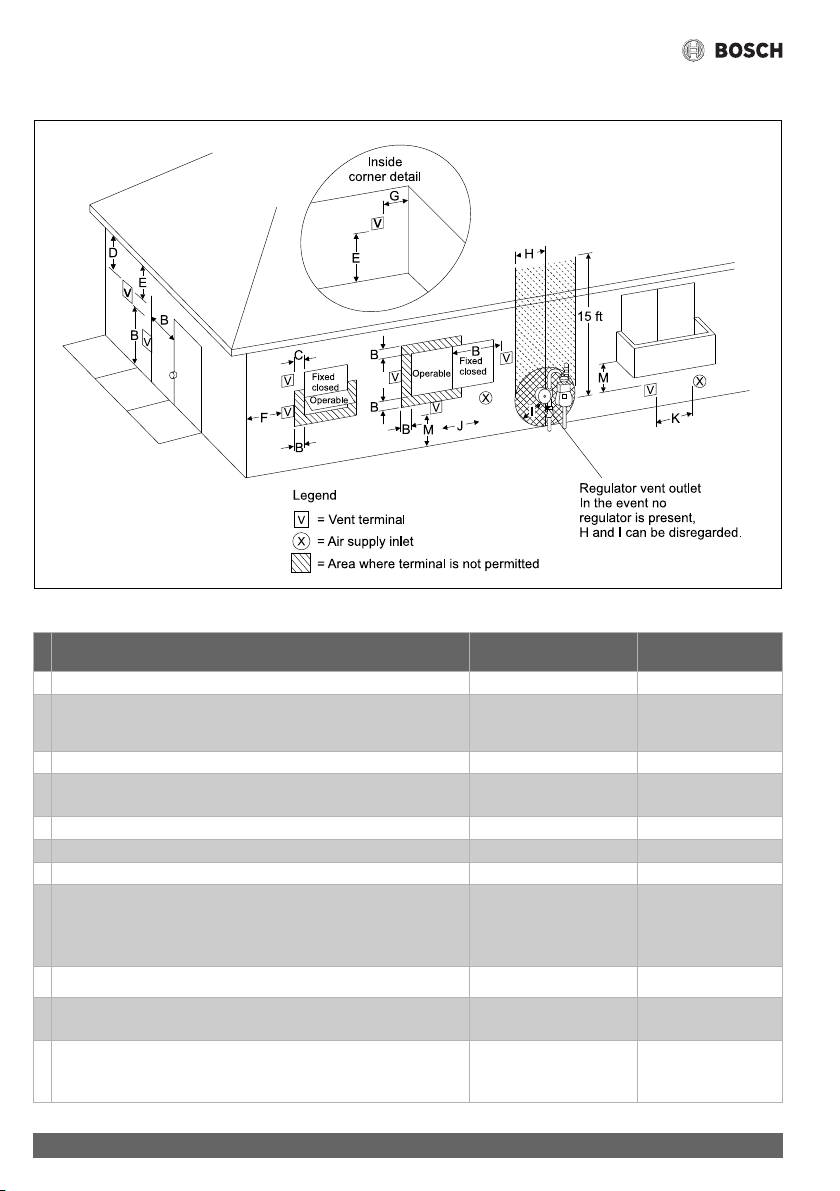
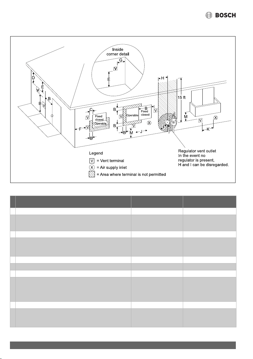
Required direct vent terminal clearances (twin pipe / concentric penetration)
Fig. 10
Canadian installations
1)2)
with direct vent terminals
U.S. installations
2)3)
with direct vent
A Clearance above grade, veranda, porch, deck or balcony 12 in. (30cm) 12 in. (30cm)
B Clearance to window or door that may be opened 36 in. (91cm) 12 in. (30cm) below or
to side of opening; 12
in. (30cm) above
C Clearance to permanently closed window * *
D Vertical clearance to ventilated soffit located above the terminal within
a horizontal distance of 2 ft (61cm) from the center line of the terminal.
* *
E Clearance to unventilated soffit * *
F Clearance to outside corner * *
G Clearance to inside corner * *
H Clearance to each side of center line extended above meter/regulator
assembly
36 in. (91cm) within a
height 15 ft (4.6m) above
the meter/ regulator
assembly
*
I Clearance to service regulator vent outlet 36 in. (91cm) *
J Clearance to nonmechanical air supply inlet to building or the
combustion air inlet to any other appliance.
36 in. (91cm) 12 in. (30cm)
K Clearance to a mechanical air supply inlet 6 feet (1.83m) 36 in. (91cm) above if
within 10 ft (3m)
horizontally

Installation instructions
25
Greentherm T9900 SE/i – 6 720 813 635 (2022/01)
Table 9
[*] Clearance in accordance with local installation codes and the requirements of the gas supplier.
L Clearance above paved sidewalk or paved driveway located on public
property
7 ft (2.13m)
4)
*
M Clearance under veranda, porch deck or balcony 12 in. (30cm)
5)
*
1) In accordance with the current CSA B149.1 Natural Gas and Propane Installation Code.
2) In accordance with the current ANSI Z223.1 / NFPA 54, National Fuel Gas Code.
3) A vent shall not terminate directly above a sidewalk or paved driveway that is located between two single family dwellings and
serves both dwellings.
4) Permitted only if veranda, porch, deck or balcony is fully open on a minimum of two sides beneath the floor.
5) If locally adopted installation codes specify clearances different than those illustrated, then the most stringent clearance shall
prevail.
Canadian installations
1)2)
with direct vent terminals
U.S. installations
2)3)
with direct vent
Installation instructions
Greentherm T9900 SE/i – 6 720 813 635 (2022/01)
26
Required other than direct vent terminal clearances (single pipe penetration)
Fig. 11
Canadian installations
1)2)
with non direct vent
U.S. installations
2)3)
with
non direct vent terminals
A Clearance above grade, veranda, porch, deck or balcony. 12 in. (30cm) 12 in. (30cm)
B Clearance to window or door that may be opened. 36 in. (91cm) 48 in. (1.2 m) below or to
side of opening; 12 in.
C Clearance to permanently closed window * *
D Vertical clearance to ventilated soffit located above the terminal
within a horizontal distance of 2 feet (61cm) from the center line
of the terminal
* *
E Clearance to unventilated soffit * *
F Clearance to outside corner * *
G Clearance to inside corner * *
H Clearance to each side of center line extended above meter/
regulator assembly
36 in. (91cm) within a
height 15 ft (4.6m) above
the meter/ regulator
assembly
*
I Clearance to service regulator vent outlet 36 in. (91cm) *
J Clearance to nonmechanical air supply inlet to building or the
combustion air inlet to any other appliance
36 in. (91cm) 48 in. (1.2m) below or to
side of opening; 1 ft
(300mm) above opening

Installation instructions
27
Greentherm T9900 SE/i – 6 720 813 635 (2022/01)
Table 10
[*] - Clearance in accordance with local installation codes and the requirements of the gas supplier.
K Clearance to mechanical air supply inlet 6 ft (1.83 m) 36 in. (91cm) above if within
10 ft (3m) horizontally
L Clearance above paved sidewalk or paved driveway located on
public property
7 ft (2.13m)
4)
*
M Clearance under veranda, porch deck or balcony 12 in (30cm)
5)
*
1) In accordance with the current CSA B149.1 Natural Gas and Propane Installation Code.
2) In accordance with the current ANSI Z223.1 / NFPA 54 National Fuel Gas Code.
3) A vent shall not terminate directly above a sidewalk or paved driveway that is located between two single family dwellings and
serves both dwellings.
4) Permitted only if veranda, porch, deck or balcony is fully open on a minimum of two sides beneath the floor.
5) If locally adopted installation codes specify clearances different than those illustrated, then the most stringent clearance shall
prevail.
Canadian installations
1)2)
with non direct vent
U.S. installations
2)3)
with
non direct vent terminals
Installation instructions
Greentherm T9900 SE/i – 6 720 813 635 (2022/01)
28
4.6.4 Recommended Vent Configuration Examples
Below are approved examples of vertical and horizontal venting
installations.
NOTICE:
Using a single pipe vent in cold climates puts the water heater
at risk of freezing, as negative air pressure is common in
buildings during cold weather. This situation will pull cold air
through the heat exchanger and can lead to damage and a water
leak and is not covered by the product's warranty. In the event
of negative air pressure causing back drafting contact Bosch for
information.
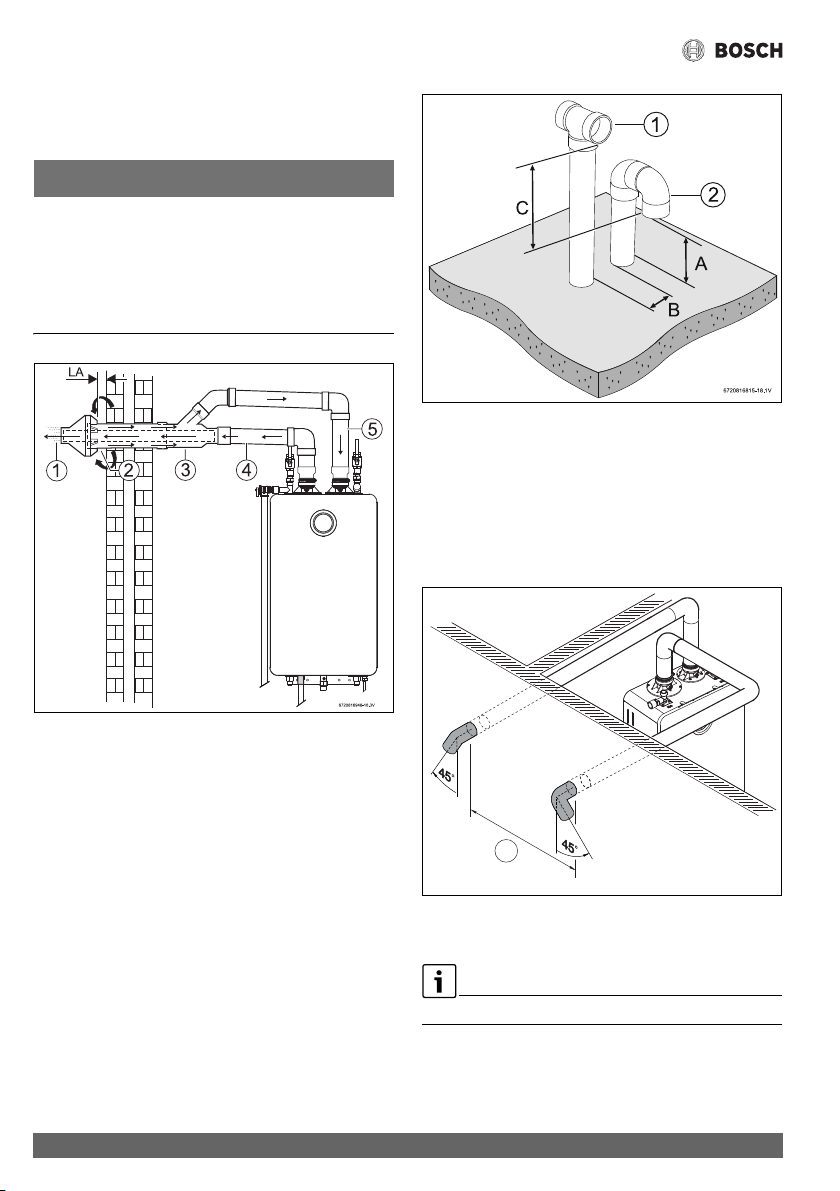
Fig. 12 Horizontal venting system (concentric vent)
[1] Exhaust
[2] Air intake
[3] Concentric Vent kit
[4] Exhaust pipe
[5] Air Intake pipe
[LA] Minimum 1"
Fig. 13 Vertical venting system
[1] Exhaust
[2] Intake
[A] 12 inches (305 mm) (18 in. for Canada) above maximum
snow level or at least 24 inches (610 mm), whichever is
greater.
[B] 12 inches (305 mm)
[C] 12 inches (305 mm) minimum above air intake opening
Fig. 14 Horizontal parallel venting system (twin pipe)
[A] 3ft minimum
Vent terminals are at the same height.
6720816815-37.1V
A
Installation instructions
29
Greentherm T9900 SE/i – 6 720 813 635 (2022/01)
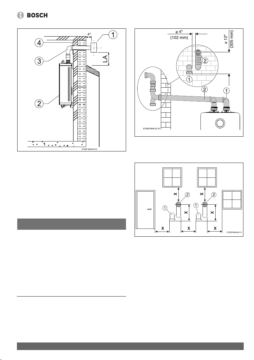
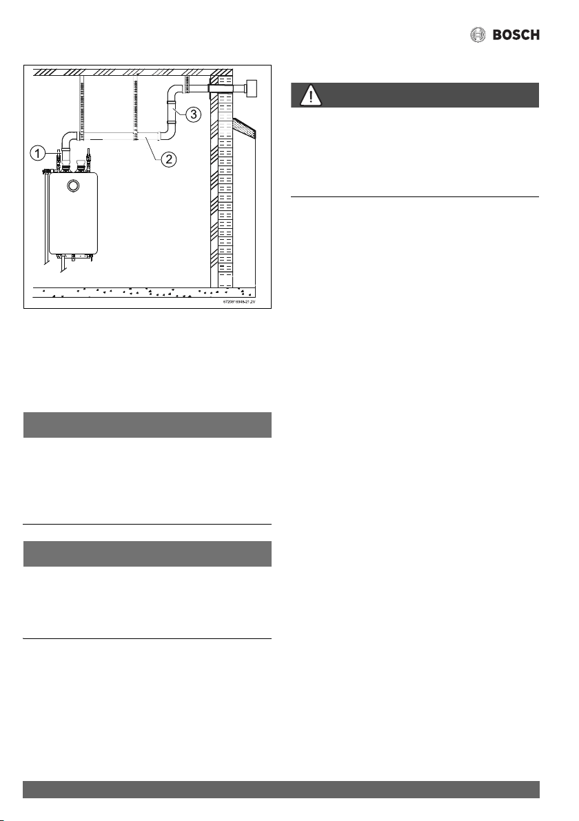
Fig. 15 Horizontal venting installation air intake piping not
shown)
[1] Termination
[2] Water heater
[3] Elbow
[4] Horizontal run should slope ¼" per foot upwards to water
heater
[LA] 12 inches (305 mm) (18 in. for Canada) above maximum
snow level or at least 24 inches (610 mm), whichever is
greater
NOTICE:
▶ The venting system must be installed in accordance with
the vent system manufacturer’s instructions.
▶ In case vent system manufacturer instructions are not
provided, it is recommended to place pipe supports every
5 feet on horizontal runs, beginning with support near
water heater.
▶ Periodic cleaning of the vent terminal and air intake screens
is mandatory.
▶ Avoid locating vent terminals near equipment, vegetation,
plants or building features which can be subject to
degradation from exhaust gases.
Fig. 16 Horizontal venting system (sealed combustion)
[1] Intake
[2] Exhaust
Fig. 17 Vent and air intake pipe position of a sealed
combustion system
[1] Intake
[2] Exhaust
[X] At least 1foot (305mm)
Installation instructions
Greentherm T9900 SE/i – 6 720 813 635 (2022/01)
30
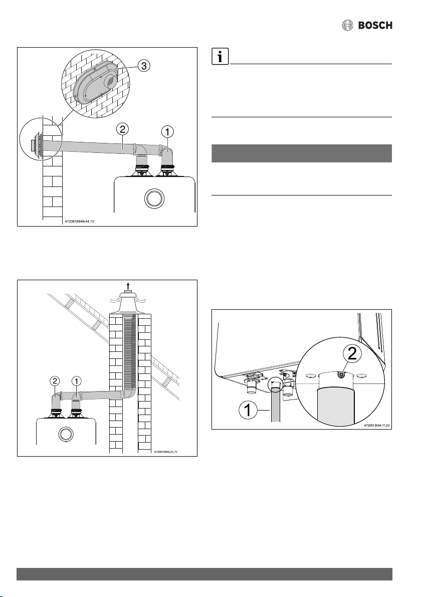
Fig. 18 Horizontal venting system (sealed combustion)
[1] Intake
[2] Exhaust
[3] Termination
Fig. 19 Vertical venting system with flex PP (sealed
combustion)
[1] Intake
[2] Exhaust
With Flex Pipe the maximum length is reduced by 60%, (applies
only to the section in flex PP). Example: 10 feet of flex PP is
equivalent to 25 feet of rigid PP.
Flex Pipe according to the suppliers instructions is for use in the
vertical part of the installation only.
4.6.5 Connecting the condensate water drain
NOTICE:
Risk of condensate pipe freezing!
▶ Do not install condensate drain tubing in areas where it may
freeze.
Appliance condensate drain installation
The appliance comes equipped with an internal condensate
drain and siphon. This drains condensation formed in the
secondary heat exchanger. Piping must be installed under the
condensate drain outlet on the water heater and piped for
disposal in accordance with local codes.
To install the condensate drain, connect a ¾"NPT adapter on
the water heater. Use only Teflon tape. Do not block vacuum
relief opening.
Fig. 20 Appliance drain installation
[1] Condensate drain connection
[2] Breather
Installing an additional breather downstream in not necessary
since this function is already included in the heater.
Installation instructions
31
Greentherm T9900 SE/i – 6 720 813 635 (2022/01)
NOTICE:
A blocked breather may cause an undesired double-siphon
effect.
▶ Ensure that the vacuum relief opening included in the
siphon is not obstructed (for example with pipe dope) to
allow correct function.
Verify condensate disposal/neutralization is in accordance with
federal, State, and local regulation.
This is a high efficiency appliance, condensate flow can be as
much as 2.1 gal/hr at full power.
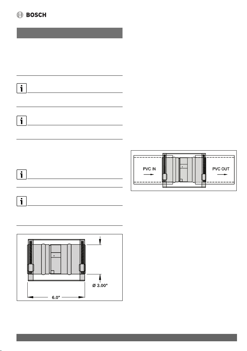
4.6.6 Backdraft reducer
The backdraft reducer (9301BFP) is the preferred option for
limiting backdraft (see fig. 21).
The backdraft reducer (9301BFP) is sized for 3" diameter PVC.
It is possible to use Backdraft reducer (9301BFP) for 2"
installations.
This requires 2" to 3" adapters.
Fig. 21 Part # 9301BFP
Installation
For the backdraft reducer to be effective, the internal flapper
must be 100% closed when the water heater is not running.
Refer to fig. 23 for preferred installation positions in the vent
system.
Installation requirements:
▶ Install the damper per the supplied manufacturer‘s
instructions.
The damper is only to be used in the exhaust vent piping.
▶ Ensure directional arrow on damper label faces in the same
direction as exhaust flow.
▶ If installed horizontally, the axis must be horizontal or
slightly pitched up towards termination to ensure damper
closes 100% when heater is not running.
▶ To allow accessibility, the damper must not be installed in
an enclosed section of vent pipe.
▶ Do not install the damper in unconditioned spaces (e.g.
attics) Condensation can build up while the heater is
running which can later freeze and potentially block the
flapper.
Fig. 22 Blackflow reducer (9301BFP) installed
6720608643-18.1V
6720608643-19.1V
Installation instructions
Greentherm T9900 SE/i – 6 720 813 635 (2022/01)
32
Fig. 23 Installation Recommendation for Placement of
Backdraft reducer
[1] Good
[2] Better
[3] Best
4.6.7 Single Pipe Venting
NOTICE:
▶ Single pipe venting not recommended in cold climates.
▶ Installations resulting in negative pressure/back draft
require sealed combustion (twin pipe /
concentric).Damage caused from back draft, ie. freezing,
are not covered by warranty.
NOTICE:
▶ When installed in an environment where corrosive
chemicals or dirty air (e.g. hair salons, car washes) are
present the sealed combustion (twin pipe or concentric) is
required.
Air combustion
DANGER:
The lack of adequate air openings may lead to improper
operation due to other appliances consuming required air.
▶ Always follow local codes and regulations of authority
having jurisdiction in case of single pipe installation in
confined spaces.
Although it is permissible to draw the air-intake from the inside,
it is not the manufacturer’s recommended installation method.
Install a 90° elbow or air intake screen on the top of the air-
intake inlet adaptor to prevent foreign objects from falling into
the unit.
If a single pipe installation is utilized, follow guidelines below for
providing adequate combustion air for the water heater as well
as any other appliances that may consume air in the same
space. Always follow local codes and regulations of the
authority having jurisdiction.
• Appliances located in unconfined spaces:
– a) An unconfined space is one whose volume is greater
than 50 cubic feet (1.42 cubic meter) per 1000 BTU/
hr (292.81 Watts) of the combined rating of all
appliances installed in the space. That would be 9950
cubic feet (281.8 cubic meters) or 1243 square feet
with 8 foot ceiling, for a single 199 kBTU water heater.
– b) In unconfined spaces in buildings of conventional
frame, masonry, or metal construction, infiltration air is
normally adequate to provide air for combustion.
• Appliances located in confined spaces:
The confined space must be provided with two permanent
openings, one commencing within 12 inches (304.8mm)
of the top and one commencing within 12 inches
(304.8mm) of the bottom of the enclosure. Each opening
must have a minimum free area of one square inch per:
– 1000 BTU/hr (292.81 Watts) if all air is taken from
inside the building
– 2000 BTU/hr (585.62 Watts) if all air is taken from the
outside by horizontal ducts
– 4000 BTU/hr (1171.24 Watts) if all air is taken from
the outside by direct openings or vertical ducts
Or the confined space must be provided with one permanent
opening or duct that is within 12 inches (304.8mm) of the
ceiling of the enclosure. This opening must have a minimum
free area of one square inch per:
– 3000 BTU/hr (878.43 Watts) if all air is taken from the
outside by a direct opening or vertical duct.
Installation instructions
33
Greentherm T9900 SE/i – 6 720 813 635 (2022/01)
Louvers, grills and screens have a blocking effect, when used,
increase the sizes of your openings by 300% for wood louvers
(as wood type will reduce the free air by 75%) and 43% for
metal louvers (as metal will reduce the free air by 30%). Refer
to the National Fuel Gas Code for complete information.
4.7 Factory settings
The appliances are supplied having been set in the factory for
the values shown on the rating plate for natural gas.
For any other adjustments see chapter 8.12.
4.7.1 Natural gas
The appliances must not be operated if the dynamic gas
pressure is less than 3.5” WC
1)
or greater than 10.5” WC.
4.7.2 Liquid propane gas (after gas conversion)
The appliances must not be operated if the dynamic gas
pressure is less than 8”WC or greater than 13” WC.
If gas conversion is needed (Natural Gas to Liquid propane
gas), see section 6.8.
WARNING:
▶ The gas type conversion must only be carried out by a
qualified contractor, see chapter 6.8.1 Gas conversion.
4.8 Gas piping & connections
Before connecting the gas supply, be sure that the heater is set
for the same gas to which it will be connected.
In the United States: The installation must conform with local
codes or, in the absence of local codes, the National Fuel Gas
Code ANSI Z223.1/NFPA 54.
In Canada: The Installation must conform to CGA B149
INSTALLATION CODES and/or local installation codes.
DANGER:
Explosion hazard!
▶ DO NOT connect to an unregulated or high pressure
propane line or to a high pressure commercial natural gas
line.
DANGER:
Explosion hazard!
▶ The heater must be isolated from the gas supply piping
system during any pressure testing of that system at test
pressures equal to or more than 0.5 psig. If overpressure
has occurred, such as through improper testing of the gas
lines or malfunction of the supply system, the gas valve
must be checked for safe operation.
GAS CONNECTIONS
▶ Install a manual gas shut off valve on the gas supply line
within easy reach of the appliance.
▶ Install a union when connecting the gas supply.
▶ Gas connection to the water heater is ¾" NPT. See chapter
4.8.1 for the minimum internal pipe diameter required.
▶ Undersized flexible appliance connector is not permitted.
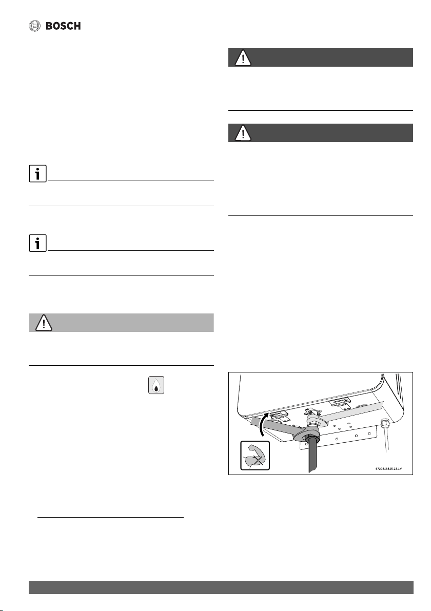
▶ National Fuel Gas Code requires that a sediment trap (drip
leg) be installed on gas appliances not so equipped. The
drip leg must be accessible and not subject to freezing
conditions. Install in accordance with the
recommendations of the serving gas supplier, see fig. 25.
▶ Tighten gas pipe with the support of a wrench, see fig. 24.
Fig. 24 Tighten gas pipe to the heater
1) To assure maximum heat input at maximum vent length
minimum gas pressure should be 5" W.C. for the 199 kBTU
models and 4" W.C. for the 160 kBTU models. For more
information see section 4.6.3.
Installation instructions
Greentherm T9900 SE/i – 6 720 813 635 (2022/01)
34
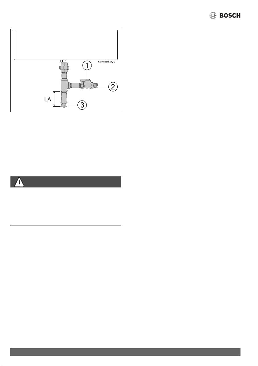
Fig. 25 Gas connection
[1] Shut off valve
[2] Gas supply
[3] Cap
[LA] Minimum 3" sediment trap, (drip leg)
Once connections are made, check for gas leaks at all joints.
Apply some gas leak detection solution to all gas fittings.
Bubbles are a sign of a leak. A combustible gas detector may
also be used to detect for leaks.
DANGER:
Explosion hazard!
▶ If you detect a gas leak, shut off the gas and ventilate the
room (open windows, doors). Tighten appropriate fittings
to stop leak. Turn the gas on and check again with a gas leak
detection solution. Never test for gas leaks using a match or
flame.
Installation instructions
35
Greentherm T9900 SE/i – 6 720 813 635 (2022/01)
GAS LINE SIZING
The gas supply piping for a single heater should be sized for a maximum draw of 199000 BTU/hr for Greentherm T9900 SE/i.
Measure the length of the gas supply line from the building's gas main to the heater and use the chapter 4.8.1 and 4.8.2 or the gas
line manufacturer’s sizing tables to determine the pipe diameter necessary. If there are more gas appliances on the line, size the gas
line according to the total maximum amount of BTU draw input rating of all appliances combined.
Note: Undersizing the gas line may result in diminished hot water flow rate and temperature, or improper appliance operation (noise
and combustion instabilities). See chapter 4.13, page 44 for the procedure to measure gas pressure. Proper gas pressure must be
confirmed at time of installation.
4.8.1 Gas Line Sizing Tables for NATURAL GAS
For your convenience, see below an excerpt from gas line sizing tables for a single NG appliance. For details, see the current NFPA
54.
Required input for 160000 / 199000 BTU/hr for the Greentherm T9900 SE/i. The gas supply system must be sized for the
combined total maximum BTU/hr load requirements of all gas appliances running simultaneously.
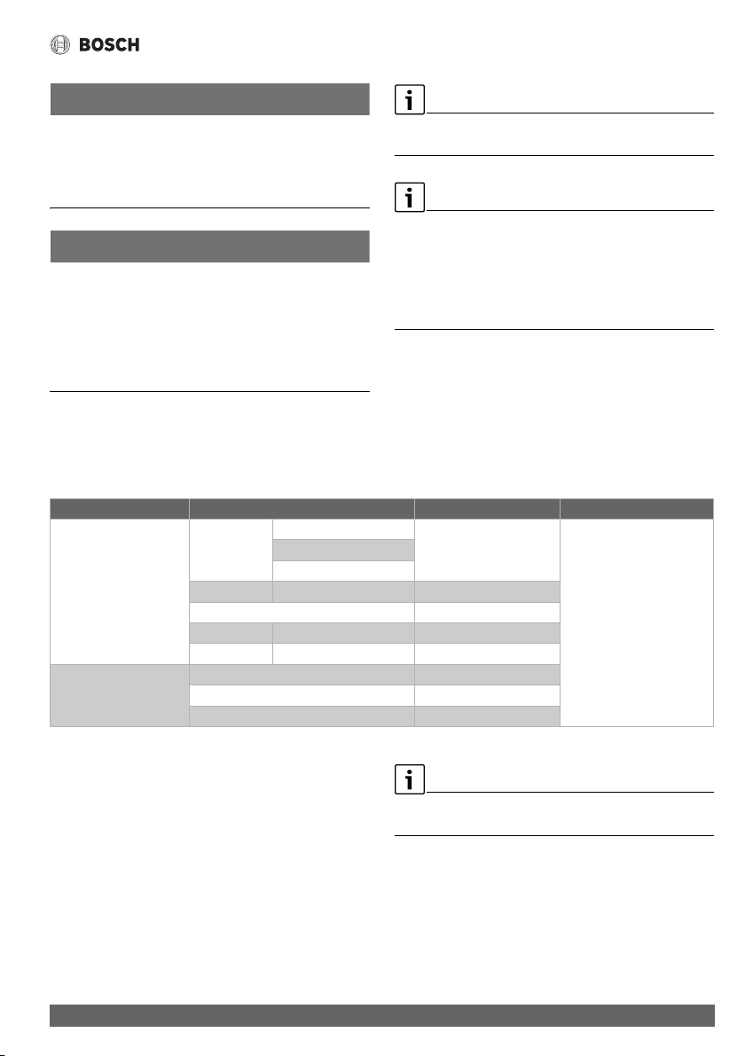
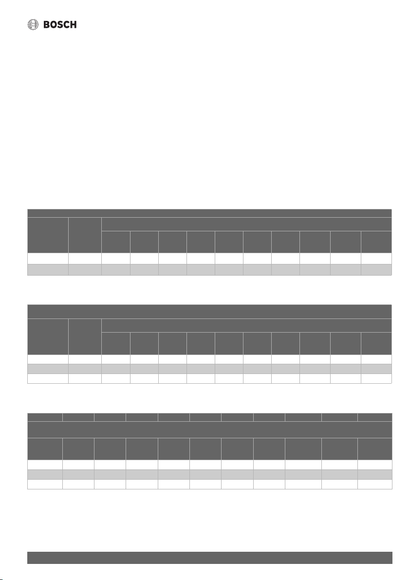
The tables below show the maximum capacity of the gas supply pipe in cubic feet per hour. Please contact your local gas supplier for
the energy content of the gas to determine the BTU/hr capacity. Use 1,000 BTU/cubic foot for rough estimations.
Table 11 Maximum pipe capacity in cubic feet of Natural Gas per hour for gas pressures of <2.0 psig (55" WC or 138 mbar) and a
pressure drop of 0.5" W.C. (1.25 mbar) based on 0.60 specific gravity gas).
Table 12 Maximum pipe capacity in cubic feet of Natural Gas per hour for gas pressures of <2.0 psig (55" WC or 138 mbar) and a
pressure drop of 3.0” W.C. (7.5 mbar) based on 0.60 specific gravity gas.
Table 13 Maximum pipe capacity in cubic feet of Natural Gas per hour for gas pressures of <2.0 psig (55" WC or 138 mbar) and a
pressure drop of 0.5" W.C. (1.25 mbar) based on 0.60 specific gravity gas).
* EHD = Equivalent Hydraulic Diameter. The greater the value of EHD, the greater the gas capacity of the tubing.
Nominal
Iron Pipe
Size, inches
Internal
Diameter
inches
Length of Black Iron Pipe (Schedule 40 Metallic Pipe), Feet
10 20 30 40 50 60 70 80 90 100
¾ 0.824 360 247 199 170 151 137 126 117 110 104
1 1.049 678 466 374 320 284 257 237 220 207 195
Initial Supply Pressure of 8.0" w.c. or Greater
Nominal
Iron Pipe
Size, inches
Internal
Diameter
inches
Length of Black Iron Pipe (Schedule 40 Metallic Pipe), Feet
10 20 30 40 50 60 70 80 90 100
½ 0.622 454 312 250 214 190 172 158 147 138 131
¾ 0.824 949 652 524 448 397 360 331 308 289 273
1 1.049 1790 1230 986 844 748 678 624 580 544 514
Length of Corrugated Stainless Steel Tubing (CSST), Feet
EHD* 10 20 30 40 50 60 70 80 90 100
30 330 231 188 162 144 131 121 113 107 101
31 383 269 218 188 168 153 141 132 125 118
37 639 456 374 325 292 267 248 232 219 208
Installation instructions
Greentherm T9900 SE/i – 6 720 813 635 (2022/01)
36
4.8.2 Gas Line Sizing Tables for LP GAS
For your convenience, see below an excerpt from gas line sizing tables for a single LP appliance. Their intended use is for pipe sizing
between the 2nd stage (low pressure) regulator and the appliance. For details, see the current NFPA 54 or NFPA 58.
Required input for 160000 / 199000 BTU/hr for the Greentherm T9900 SE/i. The gas supply system must be sized for the
combined total maximum BTU/hr load requirements of all gas appliances running simultaneously.
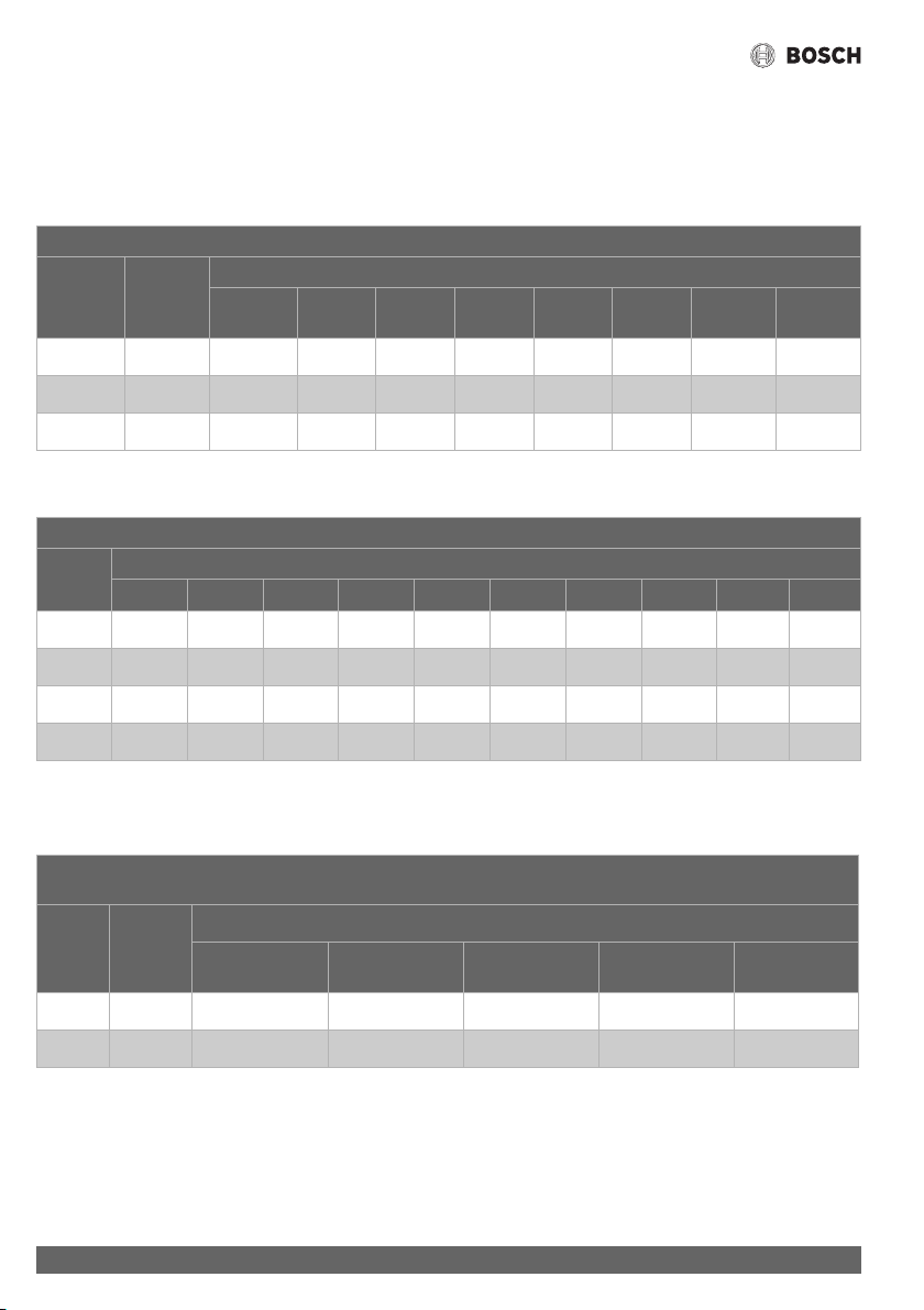
Table 14 Maximum capacity of the gas supply pipe in thousands of BTU per hour of Undiluted LP Gas at 11" W.C (0.4 psig or 27.4
mbar) based on a pressure drop of 0.5" W.C (1.25 mbar).
Table 15 Maximum capacity in thousands of BTU of the gas supply pipe per hour of Undiluted LP Gas at 11" W.C (0.4 psig or 27.4
mbar) based on a pressure drop of 0.5" W.C (1.25 mbar).
* EHD = Equivalent Hydraulic Diameter. The greater the value of EHD, the greater the gas capacity of the tubing.
Table 16 Maximum capacity in thousands of BTU of the gas supply pipe per hour of Undiluted LP Gas at 11" W.C (0.4 psig or 27.4
mbar) based on a pressure drop of 0.5" W.C (1.25 mbar).
* Source National Fuel Gas Code NFPA 54, ANSI Z223.1 - No Additional Allowance is necessary for an ordinary number of fittings.
Pipe Sizing Between Single- or Second-Stage (Low-Pressure) Regulator and Appliance
Nominal
Iron
Pipe inches
Internal
Diameter
inches
Length of Black Iron Pipe (Schedule 40 Metallic Pipe), Feet
10 20 30 40 50 60 80 100
1/2 0.622 291 200 160 137 122 110 101 94
3/4 0.824 608 418 336 287 255 231 212 197
1 1.049 1150 787 632 541 480 434 400 372
CSST Sizing Between Single- or Second-Stage (Low-Pressure) Regulator and Appliance Shutoff Valve
EHD* Length of Corrugated Stainless Steel Tubing (CSST), Feet
10 20 30 40 50 60 70 80 90 100
23 254 183 151 131 118 107 99 94 90 85
25 303 216 177 153 137 126 117 109 102 98
30 521 365 297 256 227 207 191 178 169 159
31 605 425 344 297 265 241 222 208 197 186
Tube Sizing Between Single- or Second-Stage (Low-Pressure) Regulator and Appliance
Nominal
tube
inches
Internal
Diameter
inches
Length of Semirigid Copper Tubing, Feet
10 20 30 40 50
1/2 0.527 188 129 104 89 79
5/8 0.652 329 226 182 155 138
Installation instructions
37
Greentherm T9900 SE/i – 6 720 813 635 (2022/01)
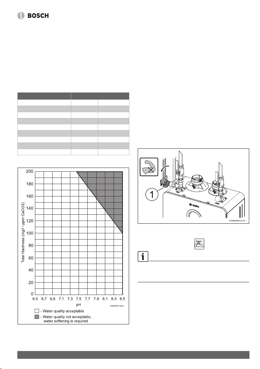
4.9 Water quality
Water quality can have an impact on appliance longevity. Water
supplied to the Greentherm T9900 SE/i must be in accordance
with table 17 and fig. 26.
For water analysis data call your local water department, or if on
a well, have well water analyzed periodically. Heavy scale will
form if the combination of water total hardness and pH exceeds
the values specified in fig. 26 (grey area), Bosch recommends
consulting a local water treatment professional for water
softening/conditioning options.
Table 17 Water quality
Fig. 26 Water total hardness and pH values
1. Total Harness and pH maximum values must be evaluated in
combination. Indicated maximum values will be reduced
according to fig. 26.
2. Combined values of total hardness and pH must be under
the indicated grey area. (e.g. the pair [180;8.3] [total
hardness; pH] is not acceptable).
Connecting the pressure relief valve (PRV)
A pressure relief valve is included in the box and must be
installed at the time of installation. No valve is to be placed
between the PRV and the heater. No reducing coupling or other
restriction may be installed in the discharge line. The discharge
line must be a minimum of 4” above a drain and installed such
that it allows complete drainage of both the PRV and the line.
The discharge line must be placed where it will not cause any
damage.
▶ Use the integrated port to install the PRV, see Fig. 27 [1].
▶ Tighten the PRV with the support of a wrench, see Fig. 27.
▶ Support all piping.
Fig. 27 Plumbing Connections (with shutoff valves) and
Pressure Relief Valve
4.10 Water connections
Water connections are on top ONLY.
Bottom connections are drain/service ports with limited flow
capacity.
Description Max. Levels
pH pH 6.5 - 8.5
TDS (total Dissolved Solids) mg/l or ppm 690
Total hardness mg/l or ppm 200
Aluminum mg/l or ppm 2.0
Chlorides mg/l or ppm 250
Copper mg/l or ppm 1.0
Iron mg/l or ppm 0.3
Manganese mg/l or ppm 0.05
Zinc mg/l or ppm 5.0
Installation instructions
Greentherm T9900 SE/i – 6 720 813 635 (2022/01)
38
NOTICE:
▶ This heater is not approved for preheated water
applications exceeding 140 °F (60 °C) for Residential
appliances, in these cases use a 3-way valve or mixing valve
must be installed before the appliance to prevent water
exceeding 140 °F (60 °C) for Residential appliances from
entering the appliance.
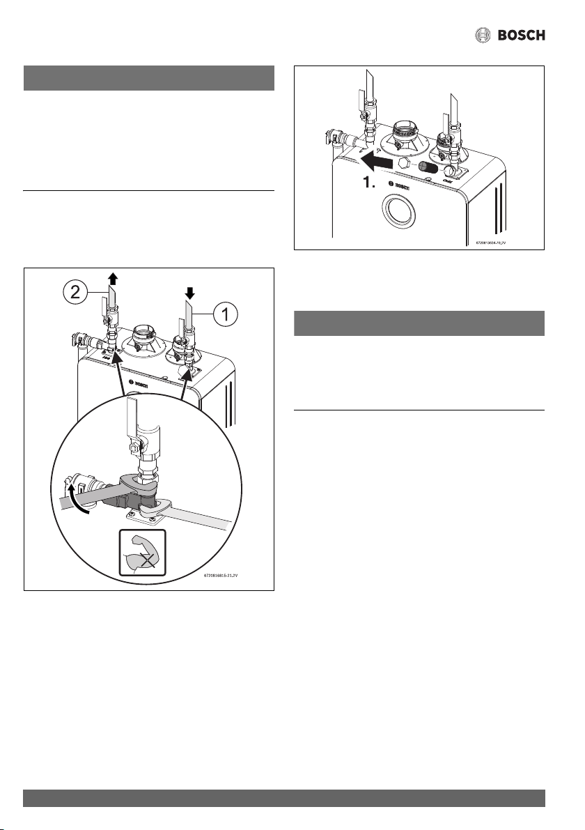
▶ When facing the heater, the ¾" cold connection is on the top
right and the hot connection is on the top left.
▶ Tighten all water connections with the support of a wrench,
see Fig. 28.
Fig. 28
[1] Cold connection
[2] Hot connection
Fig. 29 Water filter
[1] Cap
[2] Water filter
NOTICE:
Appliance damage!
Appliance will overheat if not filled with water.
▶ Ensure that the appliance is filled with water by opening a
hot water faucet, before plug in the water heater to the
power supply.
▶ The use of unions when connecting to the inlet and outlet
connections is recommended. This will facilitate any
necessary servicing.
▶ Plastic or PEX type plumbing materials are not suitable for
connecting directly to or within 18" of the water heater.
▶ Although water piping throughout the building may not be
copper, we require that copper or suitably rated stainless
steel flex line be used for the water connections for 18" on
either side of the water heater (follow local codes if more
stringent).
▶ Never sweat any piping directly to water connections, as
damage will occur.
▶ Keep water inlet and outlet pipes to no less than ¾"
diameter to allow the full flow capacity.
▶ If the cold and hot connections to the heater are reversed,
the heater will not function.
▶ Be certain there are no loose particles or dirt in the piping.
Blow out or flush the lines before connecting to the water
heater.
▶ Full port shutoff valves should be installed on both the cold
water supply and hot water outlet lines to facilitate
servicing the heater (see fig. 27).
▶ For installation on a private well system with a pressure
tank, the lowest pressure range setting recommended is
30-45 psi (2.06 - 3.1bar) to ensure optimal performance.
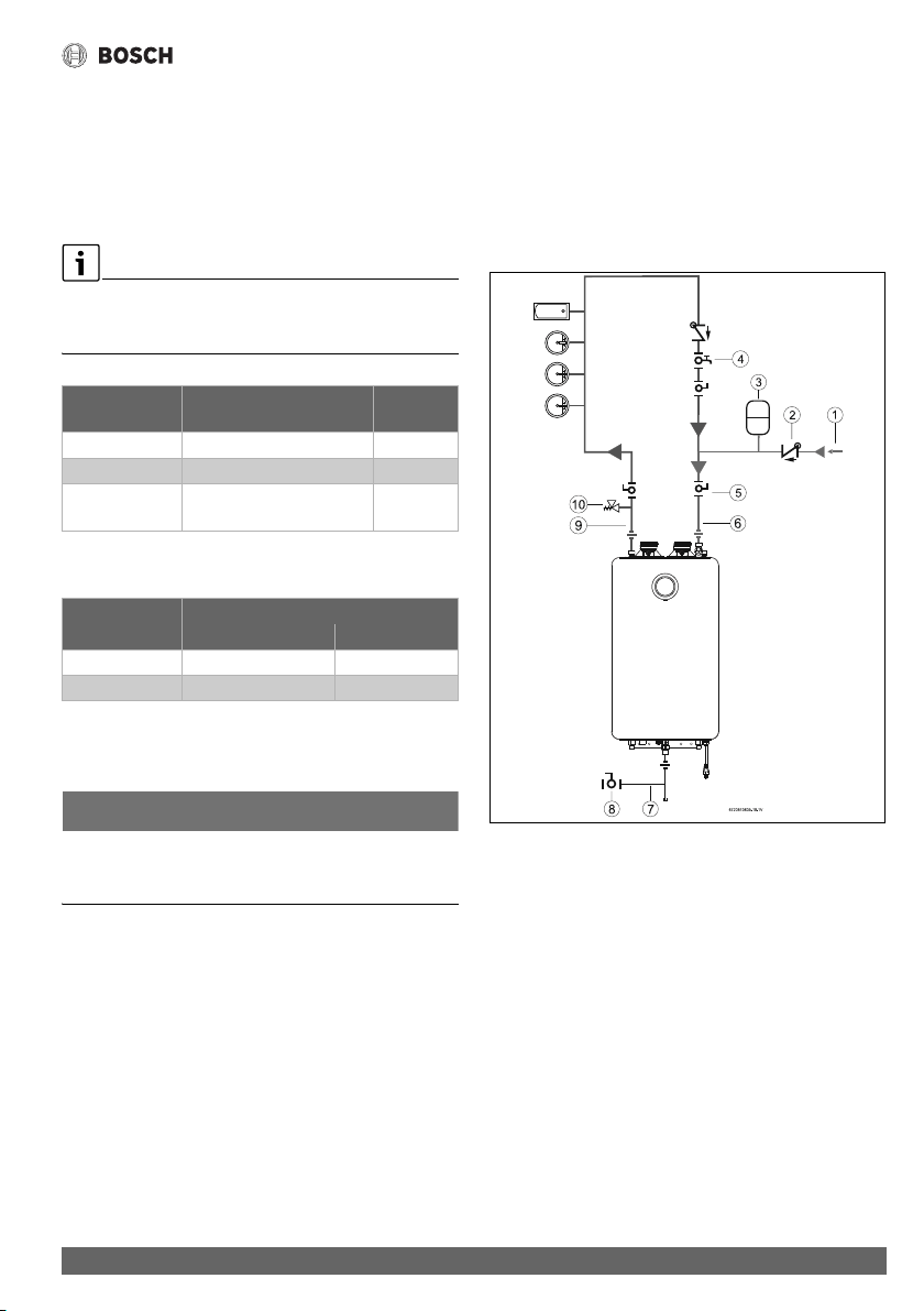
Installation instructions
39
Greentherm T9900 SE/i – 6 720 813 635 (2022/01)
4.11 Domestic hot water recirculation
The following drawings are provided to illustrate two possible
recirculation designs. These schematic is for illustration only
and must not be used for actual Installation without appropriate
engineering and technical advice from a properly licensed
professional in the locality where the installation is made.
In order to reduce the heat loss through the pipes, it’s
recommended to insulate all the pipes in the recirculation
circuit.
Table 18 Maximum total combined pipe length (hot water
supply and return lines)
Table 19 Pressure Loss in copper fittings expressed as
equivalent length of pipe
4.11.1 Start up procedure
NOTICE:
Appliance damage!
▶ Ensure that the water circuit is fill before activate
recirculation mode.
▶ Open a hot water faucet to fill the water circuit.
▶ Open the purge valve in the recirculation circuit (dedicated
mode) near the appliance water inlet.
▶ Turn on the appliance.
▶ Set the recirculation mode in HMI.
▶ Wait until there is no air in the recirculation circuit (a few
minutes).
▶ Close water faucets.
The recirculation system is operational.
4.11.2 Recirculation options
House Recirculation
Compatible with dedicated return line and cross over mode
with thermal by-pass valve.
• Dedicated mode
A dedicated return line is required in the installation.
Fig. 30 Recirculation application
[1] Cold inlet supply
[2] Check valve field supplied
[3] Expansion tank field supplied
[4] Purge Valve recirculation circuit
[5] Shutoff valves field supplied
[6] Cold water inlet
[7] Gas supply
[8] Shutoff gas valve
[9] Hot water outlet
[10] Pressure relief valve
Pipe Diameter
(copper)
Maximum Length 90° Elbows
¾" 250 ft (76m) 15
½" 166 ft (50m) 15
Combination of
both ¾" and ½"
100 ft (30m) with ¾" pipe +
100 ft (30m) with ½" pipe
15
Pipe Diameter
(copper)
Equivalent Length
90° Elbow 45° Elbows
½" 1 ft 0.5 ft
¾" 2 ft 0.5 ft
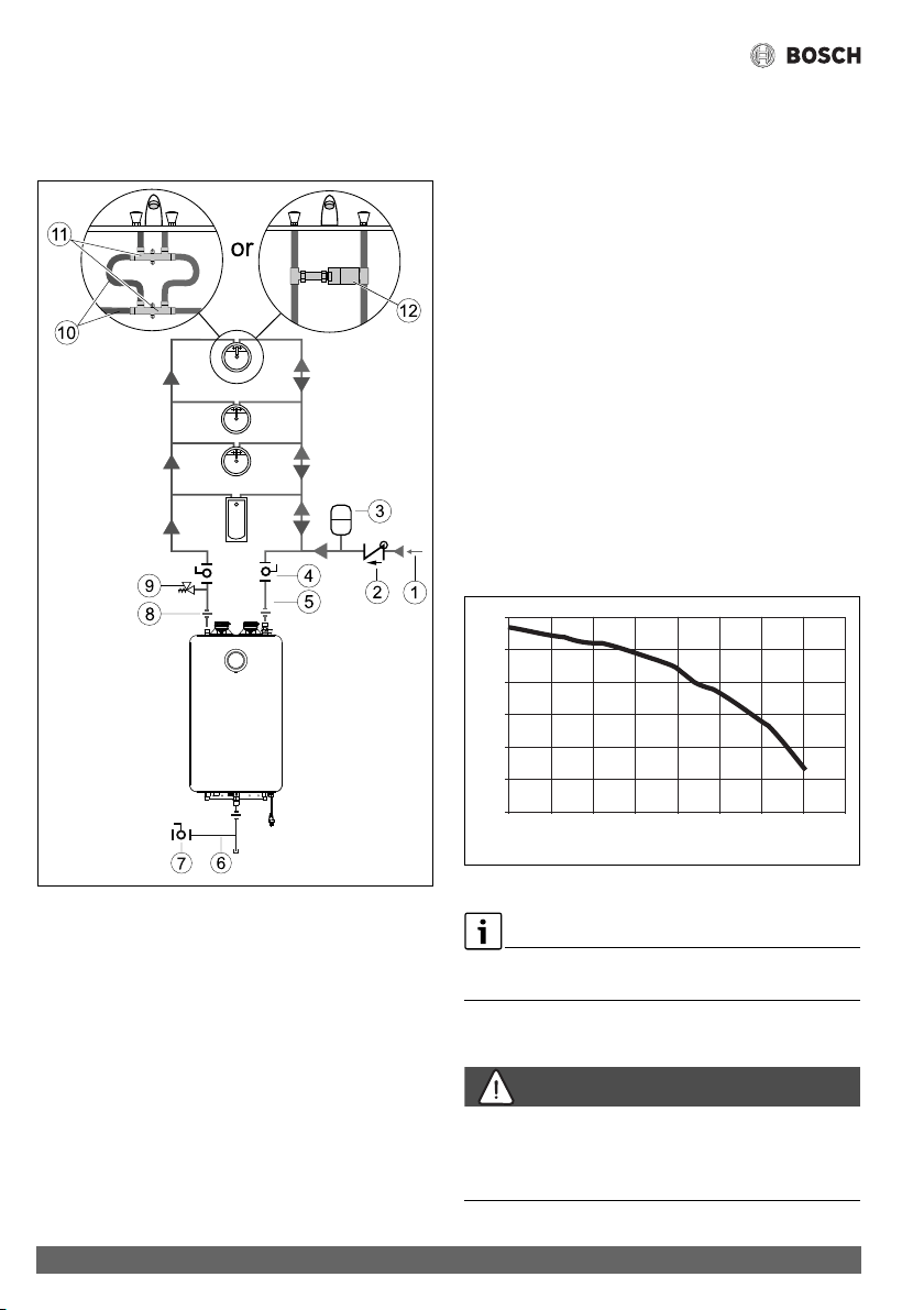
Installation instructions
Greentherm T9900 SE/i – 6 720 813 635 (2022/01)
40
• Cross Over Mode
Cross over mode requires two (2) Grundfos thermal by-pass
valves or one (1) AquaMotion AMK-ODR valve.
Fig. 31 Recirculation application
[1] Cold inlet supply
[2] Check valve field supplied
[3] Expansion tank field supplied
[4] Shutoff valves field supplied
[5] Cold water inlet
[6] Gas supply
[7] Shutoff gas valve
[8] Hot water outlet
[9] Pressure relief valve
[10] SS flexible hoses
[11] Grundfos cross-over valve (X2)
[12] AquaMotion AMK-ODR valve
Tank loading
This recirculation option gives the option of using one of three
temperature sensors to control the recirculation option. The
scheduling option is not available for tank loading.
• External NTC - 7 736 504 583
– Only compatible with Bosch cable/sensor accessory
(7736504583). Sensor must be inserted into the tank
pocket and plug in at the tank connector in bottom of
the appliance.
• Aquastat - - 7 736 504 584
– Compatible with thermostat type solution (example
Aquastat). Thermostat/Aquastat must be connected to
the appliance using the tank connector in bottom of the
appliance.
• Internal NTC
– Allows tank loading without using any external sensor/
cable. Temperature readings will be made at the
appliance.
For more information how to program each menu, see
chapter 6.5.2, page 48.
4.11.3 Recirculation internal pump
Fig. 32 Hydraulic curve
Pump performance curve, shown in Fig. 32, is an extra
information for technical installer.
4.12 Space heating applications
DANGER:
Risk of scalding!
▶ If the set point temperature is above 120°F (49 °C),
precautions should be taken to protect users of potable
water from scalding.
0123 87654
0
2
4
6
8
10
12
H [ft]
Q [GPM]
6720813635-27.1V
Installation instructions
41
Greentherm T9900 SE/i – 6 720 813 635 (2022/01)
NOTICE:
▶ The use of a flow switch is recommended to ensure DHW
priority and to prevent “cold-blow” situations when the
Bosch tankless water heater is used with an air handler.
Air handler installation must include a pump.
The flow switch should be used to disable the blower on the
air-handling system when domestic water is used.
NOTICE:
▶ Ensure the primary pump is properly sized to provide
adequate flow for the system heat load.
For external pump sizing please refer to the pressure drop
curves, fig. 34. Also remember to account for system piping
pressure loss. A minimum of 1.7 GPM is recommended to
provide adequate flow through the water heater when
determining the size of the primary pump.
Greentherm T9900 SE/i tankless water heaters are
approved for use in combination DHW and space heating
applications (open loop setup).
These water heaters are not approved for use in space heating
only applications (closed-loop setup). Bosch supports
applications of combination DHW and space heating in an open
loop configuration if plumbed in compliance with Fig. 33.
Please see warranty document for additional details.
Applications of combined DHW and space heating in an open
loop configuration, when combined with recirculation are not
recommended and desired performance is not guaranteed.
These applications will require special configurations to ensure
proper interaction between the different sub-systems (e.g. Air
Handler, Mixing valve, etc.).
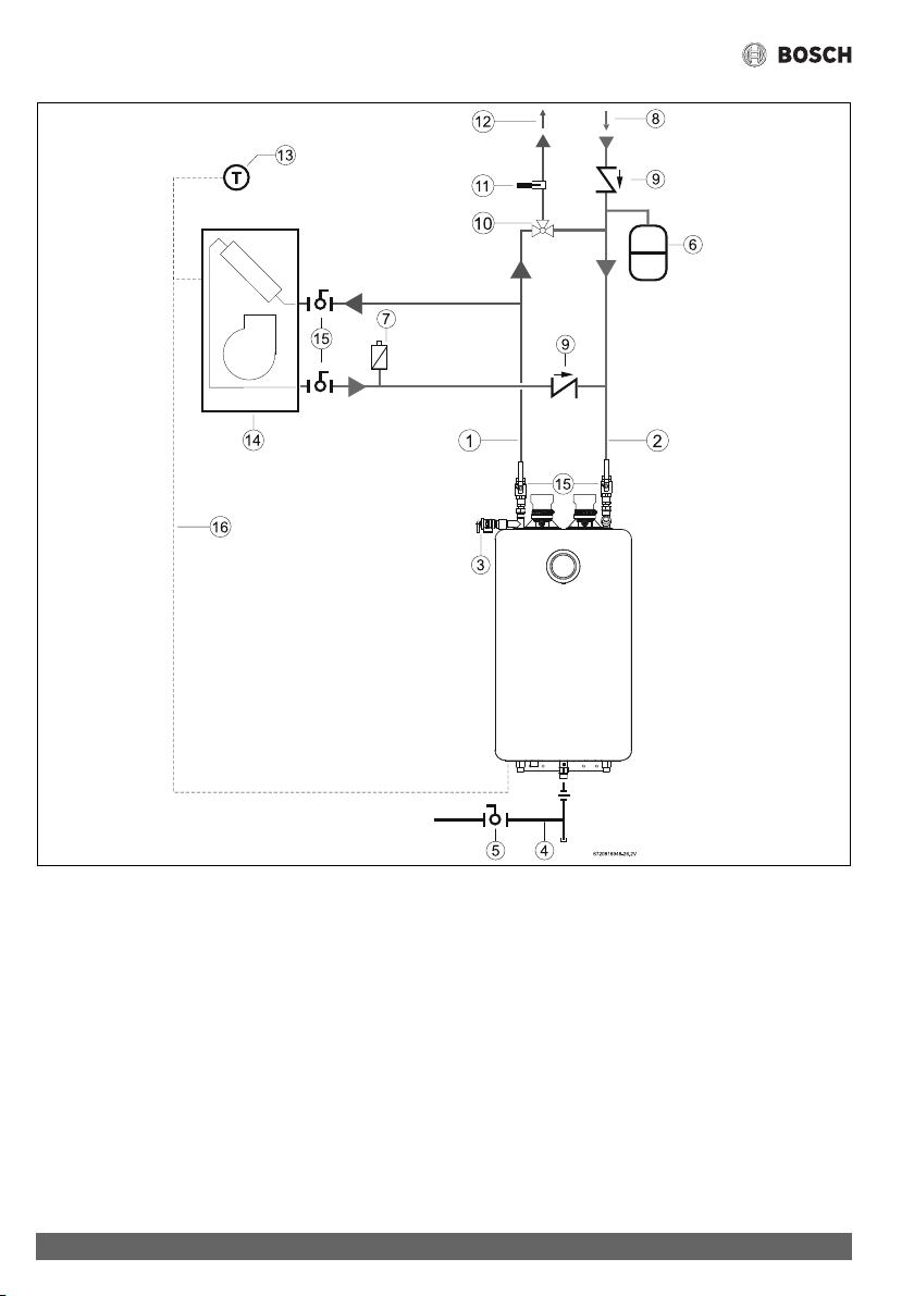
Installation instructions
Greentherm T9900 SE/i – 6 720 813 635 (2022/01)
42
Fig. 33 Hydro air system with water heater
[1] Hot water outlet
[2] Cold water inlet
[3] Pressure relief valve
[4] Gas supply
[5] Shut off gas valve (field supplied)
[6] Thermal expansion tank (as required)
[7] Air purge (field supplied)
[8] Cold water supply
[9] Check valve (field supplied)
[10] Thermostatic mixing valve (field supplied)
[11] Thermometer (optional) (field supplied)
[12] DHW outlet
[13] Thermostat (only valid if air handler includes an internal
pump) (field supplied)
[14] Air handler
[15] Shutoff valve (field supplied)
[16] NTC sensor (Bosch accessory)
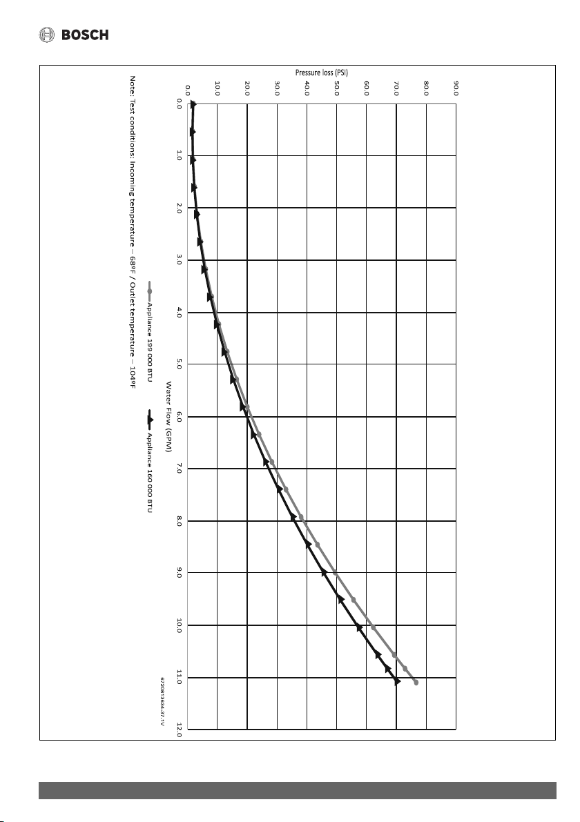
Installation instructions
43
Greentherm T9900 SE/i – 6 720 813 635 (2022/01)
Fig. 34 Pressure drop curve
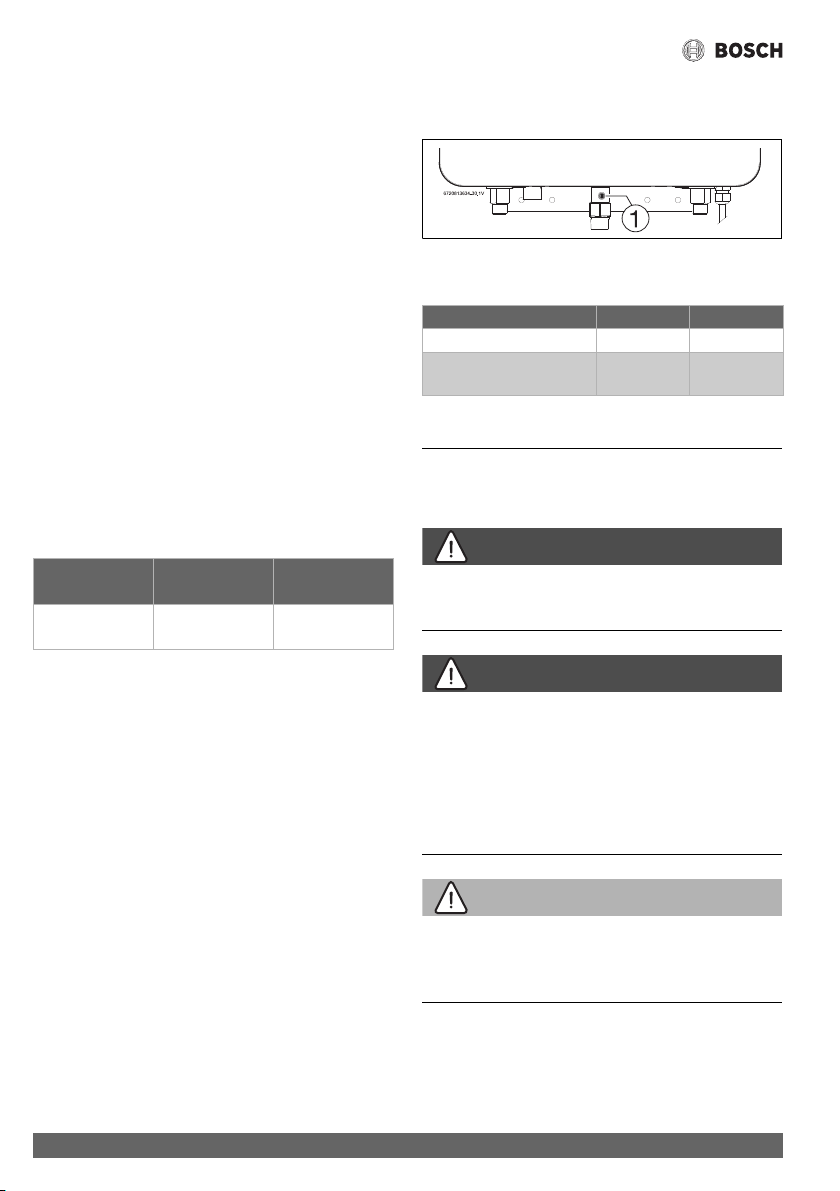
Electrical connections
Greentherm T9900 SE/i – 6 720 813 635 (2022/01)
44
4.13 Measuring gas pressure
4.13.1 Gas supply pressure
Confirm gas pressure upon installation.
Connecting manometer
▶ Shut off gas supply at installer supplied shutoff valve for
this water heater.
▶ Locate the inlet gas pressure test port (see Fig. 35).
▶ Loosen the screw inside test port fitting (do not remove)
and connect the manometer tube to the test port (see
Fig. 35).
Static Pressure Test
▶ Turn the gas supply back on.
▶ Record the static gas pressure reading in table 21.
Dynamic Pressure Test
▶ Turn ON the appliance.
▶ Access menu P1 Max. Power, see section 6.6.
Note: While in this mode the appliance will run constantly at
maximum power and allow maximum water flow.
For inlet gas pressure adjustment consider the following table:
Table 20 Minimum inlet gas pressure under full operation
▶ Operate all other gas appliances (except heater) on the
same gas piping system at maximum output.
▶ Open all hot water faucets to achieve a flow rate of at least
6 gallons per minute. (1 tub and 2 sinks should be
sufficient). If heater goes back to P2, open more hot water
fixtures to allow sufficient flow to keep the water heater in
P1.
▶ Record the lowest operating gas pressure reading in
table 21.
▶ Turn OFF the appliance.
▶ Shut off gas supply.
▶ Disconnect the manometer tube from the test point.
▶ Tighten the screw inside test point fitting.
Depending on the vent length, gas pressures below 5" W.C. for
Natural Gas or 8" W.C. for LPG may result in reduced power
output or possible error codes and must be corrected. See Gas
Connections, chapter 4.8, page 33.
Fig. 35 Gas pressure test port
[1] Gas pressure measuring port
Table 21 Inlet gas pressure readings
5 Electrical connections
5.1 Electrical power supply
DANGER:
Risk of electric shock!
▶ For safety reasons, disconnect the power supply cord to
the water heater before any service or testing is performed.
DANGER:
▶ This water heater must be electrically grounded in
accordance with the most recent edition of the National
Electrical Code. NFPA 70. In Canada, all electrical wiring to
the heater must be in accordance with local codes and the
Canadian Electrical Code, CSA C22.1 Part 1. Do not rely on
the gas or water piping to ground the metal parts of the
heater.
WARNING:
▶ Modification of or tampering with the power supply cord is
prohibited.
▶ Use of extension cords is prohibited.
The water heater requires an electrical power supply from a
120VAC / 60Hz properly rated receptacle and must be properly
grounded.
Gas type NG LPG
Inlet gas Pressure 3.5” WC
1)
1) To assure maximum heat input at maximum vent length, the
minimum gas pressure should be 5" W.C. for the 199 kBTU
models and 4" W.C. for the 160 kBTU models. For more
information see section 4.6.3.
8” WC
Gas pressure Date
Static Gas Pressure Reading
Dynamic Gas Pressure
Reading
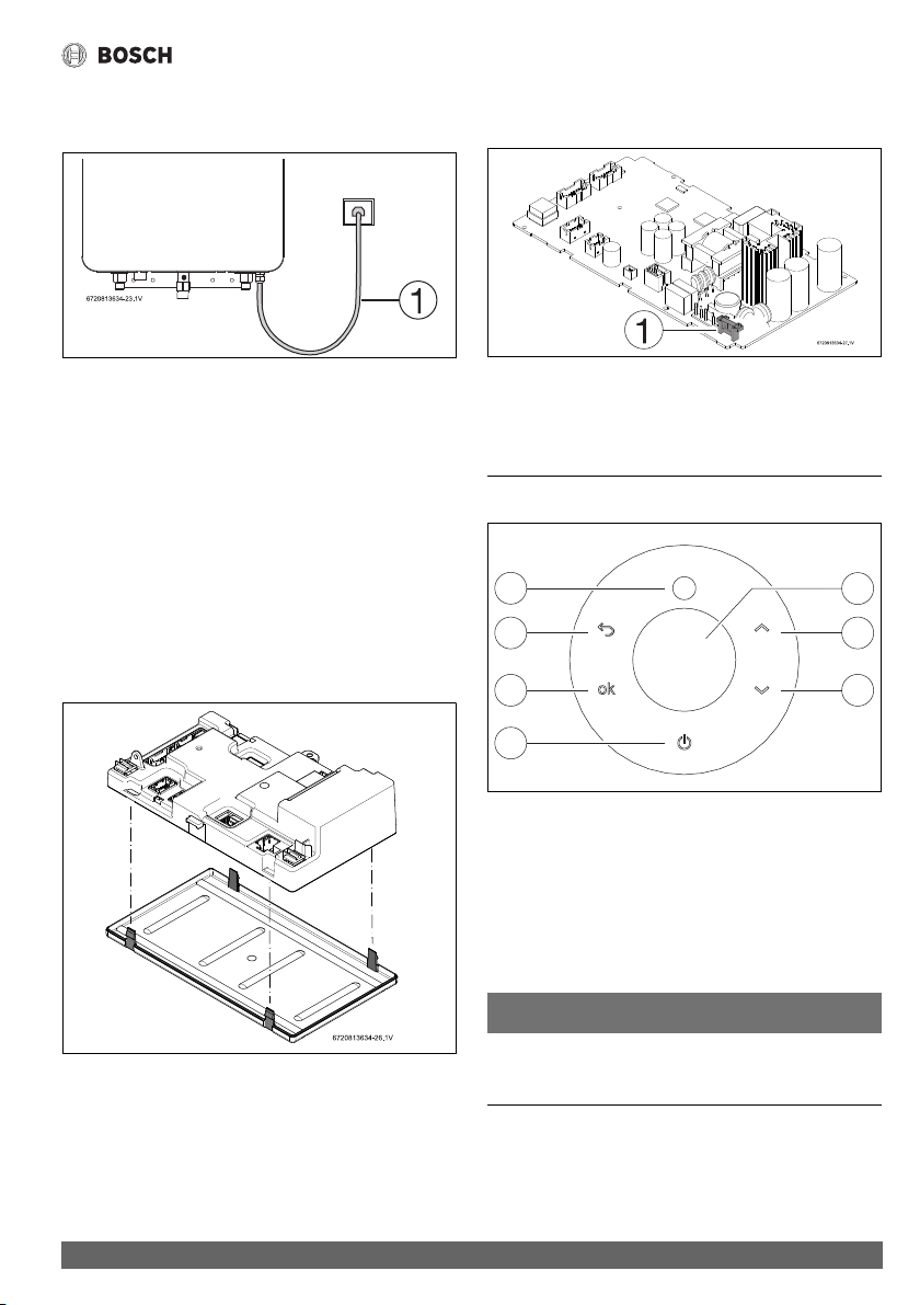
Operation instructions
45
Greentherm T9900 SE/i – 6 720 813 635 (2022/01)
The water heater is wired as shown in the wiring diagram
(chapter 10, Fig. 67).
Fig. 36 Connecting power supply cord
[1] Power cord length: 5.9 ft (1.8m).
Note: The power supply that the appliance is plugged into
should be isolated from possible water damage. Observe
proper clearance to avoid damages.
5.2 Position of the fuses in control unit
To check the fuse, proceed as follows:
▶ Disconnect the appliance from the power supply before
removing the front cover.
▶ Remove the front cover, see fig. 3, page 12.
▶ Disconnect all the cables from the control unit.
▶ Press the four snaps of the control unit and remove the
cover.
Fig. 37 Control Unit
▶ Press the four snaps inside the control unit and remove the
PCB.
▶ Check the fuse in the printed circuit board, for electrical
continuity, see fig. 38, [1].
Fig. 38 Fuse position
[1] Fuse
▶ After checking the fuse, reinstall all parts in reverse order.
6 Operation instructions
Fig. 39 Touch control display
[1] LCD display
[2] Up button
[3] Down button
[4] On/Off button
[5] Confirmation button
[6] Return button
[7] Burner status / Error symbol
NOTICE:
Instruction to clean display
▶ Wipe down with a damp cloth. Do not use any aggressive or
corrosive cleaning agents to clean the display.
7
6
5
4
2
3
6720813761-03.1V
1
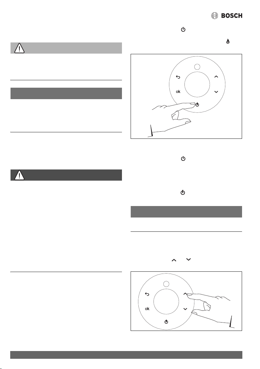
Operation instructions
Greentherm T9900 SE/i – 6 720 813 635 (2022/01)
46
6.1 For your safety read before operating your
water heater
WARNING:
Explosion hazard!
▶ If you do not follow these instructions exactly, a fire or
explosion may result causing property damage, personal
injury or loss of life.
NOTICE:
Appliance malfunction!
Strong magnetic fields can interfere with the electronics, which
can lead to appliance malfunction.
▶ Do not attach magnets to this water heater, do not install
near strong magnetic fields.
A. This appliance is equipped with electronic ignition for
lighting the main burner. When turning the heater on, follow
these instructions exactly.
WHAT TO DO IF YOU SMELL GAS,
DANGER:
Risk of explosion!
▶ Turn off the gas shut-off valve.
▶ Open windows and doors.
▶ Do not try to ignite the appliance.
▶ Do not touch any electrical switch, telephone, and do not
use outlets.
▶ Extinguish all open flames. Do not smoke! Do not use
lighters!
▶ Warn all occupants of the building. Do not ring doorbells!
▶ If you can hear gas leaking, leave the building immediately.
▶ Prevent others from entering the building and notify the
police and fire department from outside the building.
▶ From outside the building, call the gas utility company and
a trained and certified installer.
B. Use only your hand to press the on/off control button. Never
use tools. If the touch control display is dirty, wipe down with a
damp cloth. Forceful repair may result in a fire or explosion.
C. Do not use this appliance if any part has been under water.
Immediately call a qualified service technician to inspect the
appliance and to replace any part of the control system and any
gas control which has been under water.
6.2 Power
To turn ON the appliance;
▶ Touch and hold symbol for more than 3 sec.
The LCD display shows the selected temperature.
When the burner is on, the display shows symbol
(Fig. 39, [7]).
Fig. 40
To shut down the appliance;
▶ Touch and hold symbol for more than 3 sec.
6.3 Error code reset
Some possible faults can be solved by reset the appliance.
To remove error code from the display,
▶ Touch and hold symbol for more than 3sec.
The appliance will initiate the start up sequence.
NOTICE:
Appliance malfunction!
▶ If the problem persists, contact your qualified contractor.
6.4 Temperature selection
To select a hot water temperature:
▶ Touch the symbol or until the desired
temperature is displayed.
Fig. 41
6720813761-04.1V
6720813761-05.1V
Operation instructions
47
Greentherm T9900 SE/i – 6 720 813 635 (2022/01)
To increase setpoint temperature limit of the appliance,
▶Access the menu LM - Temperature Limited (
Section 6.6) and select Unlocked.
A lower temperature set point will reduce the risk of scalding,
reduce energy consumption and increase the longevity of the
heat exchanger.
Fig. 42
DANGER:
The temperature shown on the display is device measured,
always check with your hand before bathing children or elderly.
Setting the water temperature
The desired temperature of hot water can be adjusted on the
front control panel of the heater.
The water heater has an electronically controlled gas valve that
modulates the burner input in response to both varying hot
water flow rates and/or changes in any incoming and outgoing
water temperatures.
6.4.1 Programming the default setpoint temperature
Fig. 43 “Program” key
▶ Touch the symbol or to select the desired
temperature.
▶ Hold the “OK” button for 3 seconds to save the default set
point temperature.
When the display stops blinking, the default set point
temperature is saved in memory.
Selecting the default setpoint temperature
In order to select the default setpoint temperature
▶ Touch the “OK” button.
Display shows the default setpoint temperature, which is now
the hot water selected setpoint-temperature.
6.4.2 Solar Mode
If the appliance does not ignite, it means that the desired set
temperature would be exceeded even running at minimum BTU.
In this condition, the solar mode indicator will show on the
display.
In most cases, solar mode is activated if the inlet water
temperature exceeds the set point temperature minus 1 °F
(0.5 °C).
Table 22
Solar mode/warm inlet temperature activation formula
Temp. inlet ≥ [Temp. set - 1 °F (0.5 °C)]
Ex.: 111 °F (43.9 °C) ≥ [112 °F (44.4 °C) - 1 °F (0.5 °C)]
6720813761-06.1V
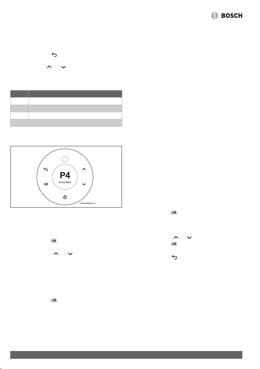
Operation instructions
Greentherm T9900 SE/i – 6 720 813 635 (2022/01)
48
6.5 Information /Adjustments menu
Access to Information / Adjustments menu
Display shows the set point temperature.
▶Touch the symbol .
Display shows P4 Information.
▶ Touch symbols or to scroll through the available
menus.
Available menus
Table 23
6.5.1 “P4” - Information
Fig. 44 P4 - Information
This menu provides access to several parameters.
▶ Access to information / adjustments menu.
Display shows P4 Information.
▶Touch the symbol .
Display shows DH Data History.
▶ Touch the symbols or to select the following
information.
– DH Data History
– OD Operation Data
– FH Failure History
– AC Consumptions
– HS About
▶ Touch the symbol to select the desired information.
DH Data History
Allows you to view two parameters:
• Operation Cycles - number of times burner has been
started.
• Operation Hours - number of hours burner has been
operating.
OD Operation Data
Allows you to view various parameters of the current operation
of the appliance:
• Hex NTC - current water temperature of the heat exchanger
outlet.
• Inlet NTC - current temperature of the temperature sensor
of the water inlet tube.
• Outlet NTC - current temperature of the temperature
sensor of the water outlet pipe.
• Air Pressure - current box pressure (mbar or psi x100).
• Fan Speed - current fan speed.
• Water Flow - total flow, through main valve + bypass.
• Ambient NTC - current temperature inside cabinet near the
fan.
• Exhaust Gas NTC - Exhaust flue gases temperature sensor.
• SS Hex NTC - Flue gases temperature sensor at the
condensing unit inlet (between heat exchangers).
• Ambient NTC - current temperature inside cabinet near the
fan.
• External Tank - current temperature on the external tank.
• Barometric pressure - current barometric pressure at
installation location.
• ION - current ionization value.
FH Failure History
Allows you to view the last 10 error codes.
▶ Touch the symbol .
Display shows the last 10 error codes.
If the display shows ellipsis (...) means that no error as
occurred.
▶ Touch the symbols or to navigate between errors.
▶ Touch the symbol to see the date and hour when the
error occurred.
▶ Touch the symbol to return to main menu.
AC Consumption
Allows for displaying, in graphic form, the consumption of gas
and water for the last 5 operations longer than 1 minute.
HS About
Allows you to view the versions of software / hardware installed
on the water heater.
6.5.2 SA - Settings
Only to be use when domestic recirculation is installed.
Display Description
P4 Information (section 6.5.1)
SA Settings (section 6.5.2)
AU Technical Settings [service mode] (section 6.5.3)
P9 Purge (section 6.5.4)
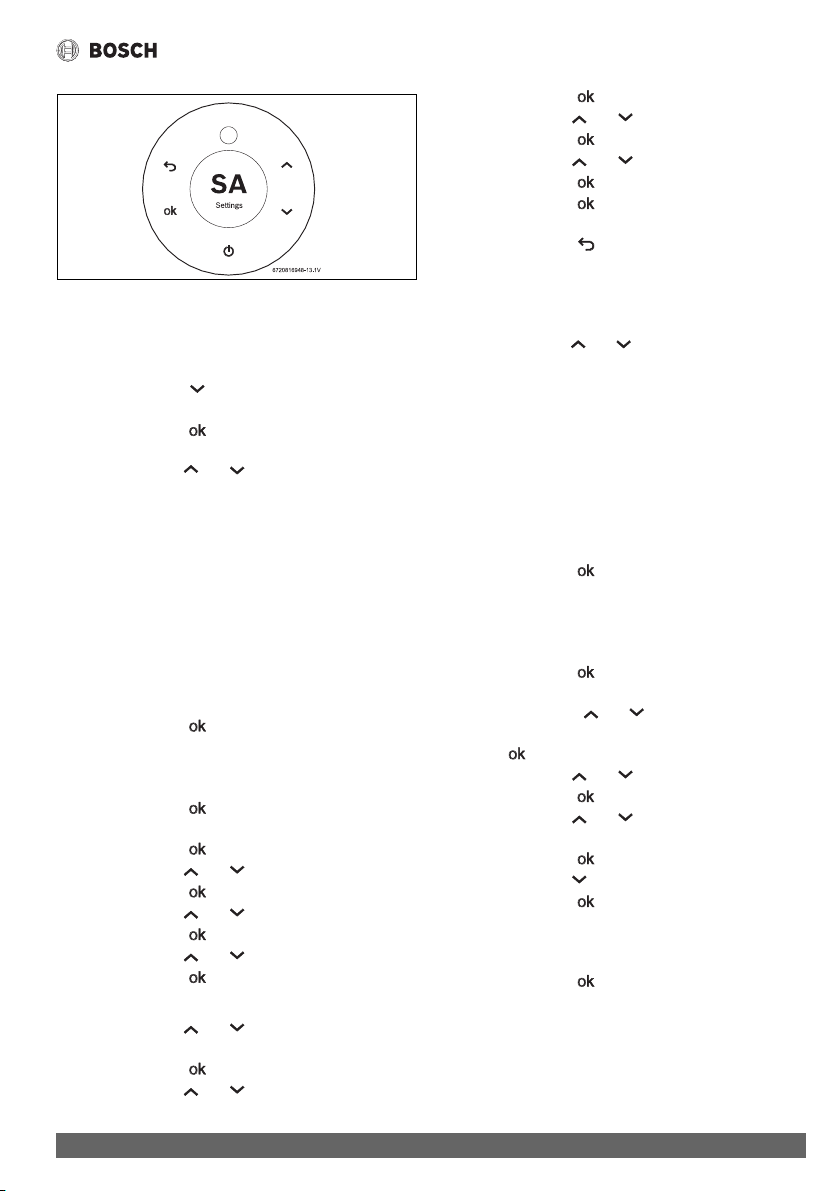
Operation instructions
49
Greentherm T9900 SE/i – 6 720 813 635 (2022/01)
Fig. 45 SA - Settings
This menu provide access to several parameters.
▶ Access to information / adjustments menu.
Display shows P4 Information.
▶ Touch the symbol until the display shows SA
Settings.
▶Touch the symbol .
Display shows A0 Clock/Date.
▶ Use the symbols or to scroll through the
information/adjustments menus.
– A0 Clock/Date
– A1 Recirculation
– A2 Vacations
– A3 Language
– A6 Display Position
– A7 Wireless Connectivity
– A8 Startup Delay
– A9 Units Set
– AA Display Timeout
– AC Lock Display
▶ Touch the symbol to select the desired information.
A0 Clock/Date
Set the time:
▶Touch the symbol .
Display shows Clock and Date menu.
▶ Touch the symbol to set the Clock.
▶ Use the symbols or to set the hours.
▶ Touch the symbol when hour is correct.
▶ Use the symbols or to set the minutes.
▶ Touch the symbol when minutes are correct.
▶ Use the symbols or to choose a.m. or p.m.
▶ Touch the symbol to exit the Clock menu.
Set the Date:
▶ Use the symbols or to choose the Date menu.
Display shows Date menu: MM / DD / YYYY.
▶Touch the symbol .
▶ Use the symbols or to set the month.
▶ Touch the symbol when month is correct.
▶ Use the symbols or to set the day.
▶ Touch the symbol when the day is correct.
▶ Use the symbols or to set the year.
▶ Touch the symbol when the year is correct.
▶ Touch the symbol to exit the Date menu.
Clock and Date are defined.
▶ Touch the symbol , the Hours and Clock blink 3 times
and exit menu.
A1 Recirculation
Choosing a recirculation program:
▶ Use the symbols or to scroll through the options.
– HR House Recirculation
– TL Tank Loading
– OFF Off
HR House Recirculation
• AA Always Active
• SCH Schedule
AA Always Active
Set the Always Active:
▶ Touch the symbol , to select ON.
Recirculation will be always active.
SCH Schedule
Creating a Schedule:
▶ Touch the symbol , to select Schedule.
Display shows week days.
▶ Touch the symbols or to select the desired week
day.
▶ Press ,
▶ Use the symbols or to choose option Add New.
▶ Touch the symbol , to enter the recirculation program.
▶ Use the symbols or to choose the beginning
hour.
▶ Touch the symbol , to set the beginning hour.
▶ Use the symbols to choose the end hour.
▶ Touch the symbol , to set the ending hour.
A recirculation period is defined.
The user can add additional recirculation periods on the
same day.
▶ Touch the symbol , to select Add New and repeat all
steps mentioned above.
Copy recirculation program,
The user can copy the recirculation period(s) to other week
days.
Operation instructions
Greentherm T9900 SE/i – 6 720 813 635 (2022/01)
50
▶ Use the symbols or to select the day of the week
to be copied.
▶ Use the symbols or to choose option Copy to.
▶Touch the symbol .
Display shows week days.
▶ Touch the symbol to select the day of the week.
▶ Use the symbols or to choose another week day.
When week days are selected,
▶ Touch the symbol to validate operation.
▶ Touch the symbol to exit.
Deleting a recirculation program,
▶ Use the symbols or to select the day of the week
to be deleted.
▶Touch the symbol .
▶ Use the symbols or to choose option Delete.
▶Touch the symbol .
▶ Use the symbols or to choose a recirculation
period.
▶ Touch the symbol twice to delete recirculation period.
▶ Touch the symbol to exit.
TL Tank Loading
▶Touch the symbol .
Display shows following menu.
– External NTC
– Internal NTC
– Aquastat
Select the menu according with the installation.
OFF
Set the OFF:
▶Touch the symbol , to select OFF.
Recirculation will not be active.
A2 Vacations
Set Vacation time.
The burners will not activate while the appliance is in vacation
mode.
▶Touch the symbol .
Display shows Vacation menu.
▶ Use the symbol to choose On.
On starts to blink.
▶ Touch the symbol to define first day of vacation:
MM/DD/YYYY.
▶ Use the symbols or to set the month.
▶ Touch the symbol when month is correct.
▶ Use the symbols or to set the day.
▶ Touch the symbol when day is correct.
▶ Use the symbols or to set the year.
▶ Touch the symbol when year is correct.
▶ Use the symbols or to define the total of days.
▶ Touch the symbol to finish programming.
▶ Touch the symbol to activate vacation program.
Deactivating the vacation program.
▶ Use the symbol or to select “Off”
Off starts to blink.
▶ Touch the symbol .
Off option is selected.
▶ Touch the symbol to deactivate vacation program.
A3 Language
How to set the language,
▶ Use the symbols or to choose the language.
▶ Touch the symbol .
The language is selected.
A6 Display Position
Set the position:
▶ Touch the symbol ,
Adjust “Burner status/Error symbol” (Fig. 39, [1])
display position;
• Vertical
• Horizontal
▶ Touch the symbol ,
Adjust “LCD display” position (Fig. 39, [7]);
• Vertical
• Horizontal
After the display's position has been adjusted:
▶ Touch the symbol to exit.
A7 Wireless Connectivity
For more information:
▶ section 6.9 "Wi-Fi connection".
A8 Startup Delay
This menu allows programing a burner start delay between 0
and 60 seconds, after detecting water flow.
▶ Access to information / adjustments menu.
Display shows SA Settings.
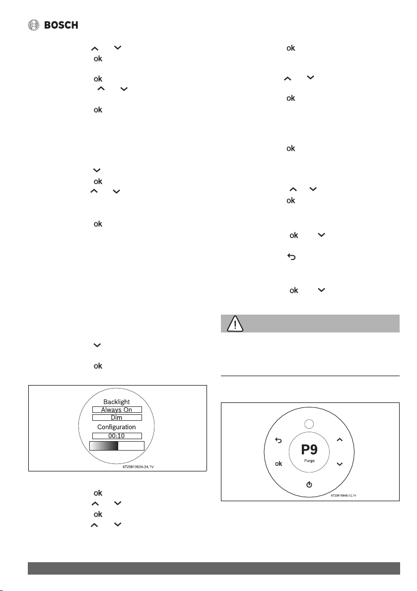
Operation instructions
51
Greentherm T9900 SE/i – 6 720 813 635 (2022/01)
▶ Use the symbols or to select A8 Startup Delay.
▶Touch the symbol .
Display shows Startup Value(s).
▶Touch the symbol .
▶ Touch the symbols or to define, in seconds, the
delay to start-up after detection of the water flow.
▶ Touch the symbol after reaching the desired value.
A9 Units Set
This menu allows you to choose the units visible on the display.
▶ Access to information / adjustments menu.
Display shows SA Settings.
▶ Touch the symbol until A9 Units is in the display.
▶Touch the symbol .
▶ Use the symbols or to select measurement units.
– Metric ( °C l/min)
– Imperial ( °F gal/min)
▶ Touch the symbol after selecting the desired units.
The selected units blinks, display indicates A9 Units.
AA Display Timeout
Activation of brightness control increases energy savings when
the appliance is idle.This menu lets you control 3 parameters of
the display when idle, or when the unit is not in use:
• enable / disable brightness control
• after which time the brightness control is activated
• brightness level
▶ Access to information / adjustments menu.
Display shows SA Settings.
▶ Touch the symbol until the display shows AA Display
Timeout.
▶Touch the symbol .
Display shows Backlight.
Fig. 46 Backlight control menu
▶Touch the symbol .
▶ Use the symbols or to select DIM.
▶Touch the symbol .
▶ Use the symbols or to set between 10 seconds
and 1 hour.
▶ Touch the symbol after reaching the desired value.
The time is defined, the brightness value must now be
programmed.
▶ Use the symbols or to set the brightness of the
display when in period of inactivity.
▶ Touch the symbol after reaching the desired
brightness.
AC Lock Display
This menu allows to lock the display.
▶ Touch the symbol .
Display shows following menu.
– Off
– On
▶ Touch the symbols or to select the desired option.
▶ Touch the symbol .
The current selection is in green color.
To unlock the screen,
▶ Touch the symbols and more than 2 seconds to
unlock touch screen.
▶ Touch the symbol to return to main menu.
The display will lock after a few seconds of inactivity.
To unlock the display,
▶ Touch the symbols and for 2 seconds.
6.5.3 AU - Technical Settings
WARNING:
▶ Only a qualified technician is authorized to access this
menu.
▶ See section 6.6.
6.5.4 “P9” - Purge
Fig. 47 P9 - Purge
This menu allows you to purge the exhaust circuit.
▶ Access to information / adjustments menu.
Display shows P4 Information.
Operation instructions
Greentherm T9900 SE/i – 6 720 813 635 (2022/01)
52
▶ Touch the symbol until the display shows P9 Purge.
After 2 sec. the fan starts working to purge the exhaust
circuit.
The fan remains running until the Purge menu is exited, to do
so:
▶Touch the symbol .
6.6 Service menu - AU Technical Settings
Accessing the AU Technical Settings menu
▶Touch the symbol .
Display shows P4 Information.
▶ Touch symbols or to select AU Technical
Settings menu.
▶Touch the symbol .
Display shows authentication menu (password input).
▶ The password is 1886.
Authentication completed.
▶Touch the symbol .
Access to installer exclusive menus.
• P7 - Gas Type (LPG, NG)
• LM - Temperature Limited
• RS - Recirculation Settings
• PC - Cascading
• CA - Combustion Adjust
• PA - Water Actuator
• PF - Bypass Valve
• PE - Appliance Type
• AB - Region Selection
• A4 - Demonstration
P7 Gas Type (LPG, NG)
For more information:
▶ section 6.8.
LM Temperature Limited
Unlock the Temperature Limit
▶Touch the symbol .
Display shows following menu.
– Unlocked
–Locked
The current selection is in green color.
▶ Touch symbols or to select Unlocked.
▶Touch the symbol .
▶ Touch the symbol to return to main menu.
RS Recirculation Settings
To define recirculation comfort level,
▶ Touch the symbol .
▶ Touch symbols or to define comfort level.
– 1
– 2
–...
– 9
Choosing a higher comfort level (9) will set the recirculation
water temperature closer to the set point defined on the
water heater. Choosing a lower value (1) will favor
efficiency at the expense of recirculation temperature
comfort.
▶ Touch the symbol .
▶ Touch the symbol to return to main menu.
PC Cascading
Use this menu only after installing the cascading kit
(7709003962).
▶ Only a qualified technician can change this parameter.
To define cascading settings,
▶ Touch the symbol .
▶ Touch symbols or to move between menus.
• State
–Off
–On
• Mode (Only available if Sate On is selected).
–Primary
–Secondary
Cascading and internal recirculation won't be able to perform at
the same time. Therefore, when cascading is activated, internal
recirculation is turned off automatically and vice-versa.
For more information,
▶ See Cascading kit installation manual.
CA Combustion Adjust
For more information:
▶ section 8.12.
PA Water Actuator
For more information:
▶ section 6.7.
Operation instructions
53
Greentherm T9900 SE/i – 6 720 813 635 (2022/01)
PF Bypass Activation
To Enable or Disable bypass function.
▶Touch the symbol .
Display shows following menu.
– Off
–On
The current selection is in green color.
▶ Touch symbols or to select the desired option.
▶Touch the symbol .
▶ Touch the symbol to return to main menu.
PE Appliance Type
This menu shows the technical specifications of the appliance.
• AP Appliance Power
• ML Model
• TP Type
AP Appliance Power
▶Touch the symbol .
Display shows appliance power (default set).
– 199K BTU
or
– 160K BTU
▶ Touch the symbol to exit.
▶ Touch symbols or to scroll through other menus.
ML Model
▶Touch the symbol .
Display shows appliance model.
– Indoor
▶ Touch the symbol to exit.
▶ Touch symbols or to scroll through other menus.
TP Type
▶Touch the symbol .
Display shows appliance model.
– Residential
▶ Touch the symbol to exit.
AB Region Selection
▶Touch the symbol .
Display shows following menu.
– Europe
– North America
A4 Demonstration
Simulates in the display, the appliance is functioning.
(Only available when burner is not working)
6.7 Water valves calibration
Water valve calibration must be done when main water valve or
bypass valve is replaced. Also required when electronic control
unit is replaced.
The water valve calibration process takes several minutes.
▶ Do not interfere with the appliance.
Only possible after access Technical Settings menu (
section 6.6).
6.7.1 MF main water valve auto calibration
▶Open one hot water faucet.
Before moving to the next step:
▶ make sure there is water flow.
▶ Access menu PA.
▶ Touch symbol OK.
▶ Touch symbols or to select MF main valve.
▶ Touch symbol OK.
The appliance will start the auto calibration of main valve.
Water flow will shut-off.
▶ Wait until indication of calibration completed appears on
the screen.
▶ Touch the symbol to return to main menu.
6.7.2 BP bypass valve auto calibration
▶Open one hot water faucet.
Flow rate between 0.80 GPM and 1.80 GPM is required.
It's possible to confirm this value by entering BP bypass
water valve menu.
▶ Access menu PA.
▶ Touch symbol OK.
▶ Touch symbols or to select BP bypass water
valve.
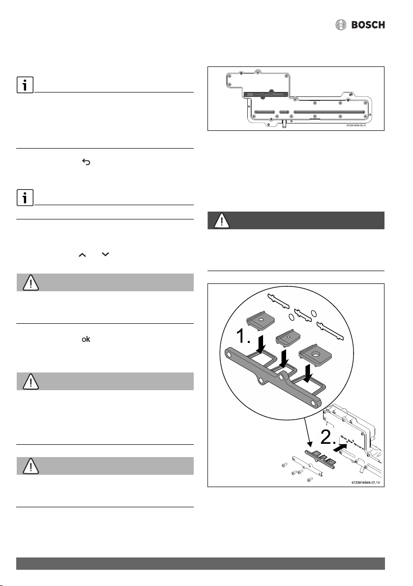
Operation instructions
Greentherm T9900 SE/i – 6 720 813 635 (2022/01)
54
▶ Touch symbol OK.
The appliance will start the auto calibration of the bypass
valve.
The display shows the flow rate.
▶ You should adjust the flow rate at the beginning of the
calibration process.
▶ Wait for the indication that the calibration is completed to
appear on the screen.
▶ Touch the symbol to return to main menu.
6.8 Gas type
Only possible after access Technical Settings menu.
▶ Access to menu P7 Gas Type.
Display shows appliance gas type.
▶ Use the symbols or to confirm gas type.
WARNING:
The gas type conversion must only be carried out by a qualified
contractor.
▶Touch the symbol .
Display blinks 3 times and return to P7 menu.
6.8.1 Gas conversion from NG to LPG
WARNING:
Fatal accidents!
Before any service or testing in the appliance,
▶ Turn off the appliance.
▶ Disconnect the power supply cord.
▶ Shut off the gas supply.
WARNING:
The gas type conversion must only be carried out by a qualified
contractor.
▶ Turn Off the appliance.
▶ Remove the front cover from the appliance (section 3.3.2).
▶ Remove the four screws that retain the cover plate to the
gas manifold, see fig. 48 (plate in grey color).
Fig. 48 Gas manifold
▶ Remove metal plate and seal.
▶ The 3 restrictor plates should be pre-assembled onto their
tray, but if loose in box, follow installation instructions, as
shown in Figs. 49 and 50 [1].
▶ Insert the LP conversion plate in the appropriate location
shown in Figs. 49 and 50 [2].
DANGER:
▶ All three flow restrictors and seal must be assembled
according to the Fig. 49, to assure correct appliance
performance.
Fig. 49 199kBTU appliance gas conversion kit
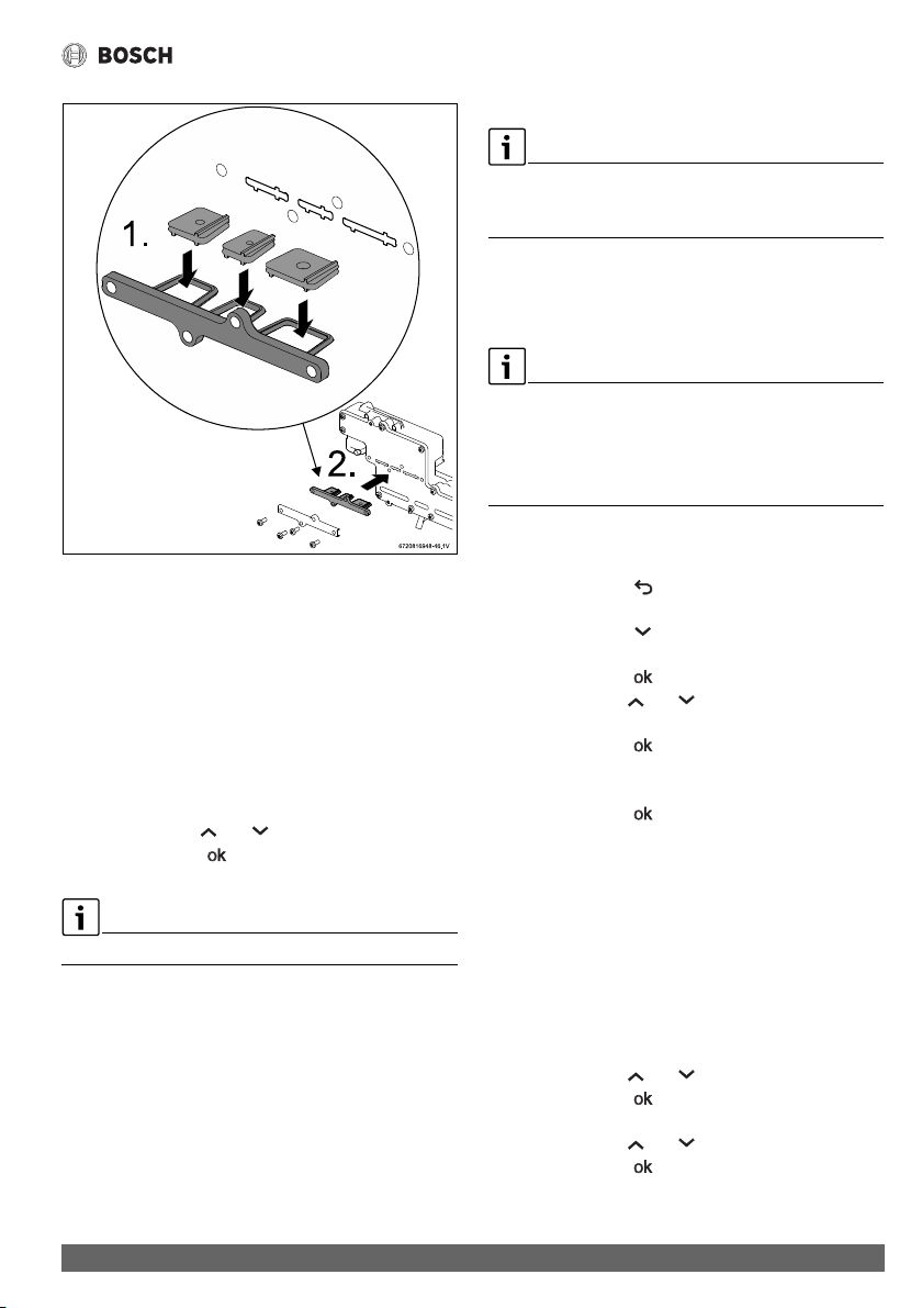
Operation instructions
55
Greentherm T9900 SE/i – 6 720 813 635 (2022/01)
Fig. 50 160kBTU appliance gas conversion kit
▶Tighten the four screws.
▶ Open the gas supply valve.
▶ Turn On the appliance.
▶ Open a faucet and check for gas leak (e.g. use leak detector
fluid, like water and soap, over and around the metal plate)
and act accordingly.
▶ Place the front cover in the appliance.
▶Access the Technical Settings menu (section 6.6).
▶Access to menu P7 Gas Type.
Display shows appliance gas type.
▶ Use the symbols or to choose gas type LPG.
▶Touch the symbol .
The display blinks to confirm the change.
The appliance will go through an initialization process.
▶ Update “TYPE OF GAS” in the rating plate of the appliance
using the label provided with the conversion plates.
▶Confirm combustion adjustment and, if necessary, adjust
Gas and Air flow parameters, see chapter 8.12 for more
information.
6.9 Wi-Fi connection
Only available in T9900 SEi model. For T9900 SE160/199
models, a wireless connectivity accessory is available with Wi-
Fi accessory module.
6.9.1 Wi-Fi activation
Before activating Wi-Fi module,
▶ Unplug the appliance from the power supply.
The Wi-Fi module must be activated within 60 minutes after
plugging in the appliance to the power supply.
If an error message is displayed or cannot configure Wi-Fi
menu.
▶ See section 6.9.3 "Problem solving to activate Wi-Fi".
▶ Plug in the appliance to the power supply.
▶ Access to information / adjustments menu.
▶ Touch the symbol .
Display shows P4 Information.
▶ Touch the symbol until the display shows SA
Settings.
▶ Touch the symbol .
▶ Use the symbols or to select A7 Wireless
Connectivity
▶ Touch the symbol .
Display shows,
– WF Wi-Fi
▶ Touch the symbol .
Activate Wi-Fi module
Two options are available to activate Wi-Fi module in the
appliance;
▶ Connect the appliance to a network (SC Scan)
-or-
▶ Configure Hotspot menu in the appliance (HT Hotspot)
(This option is generally chosen in case there is no
domestic Wi-Fi connection available.)
How to connect the appliance to a network, SC Scan menu,
▶ Use the symbols or to select SC Scan.
▶ Touch the symbol .
Display shows list of available networks.
▶ Use the symbols or to select the Wi-Fi network.
▶ Touch the symbol .
Insert network password.
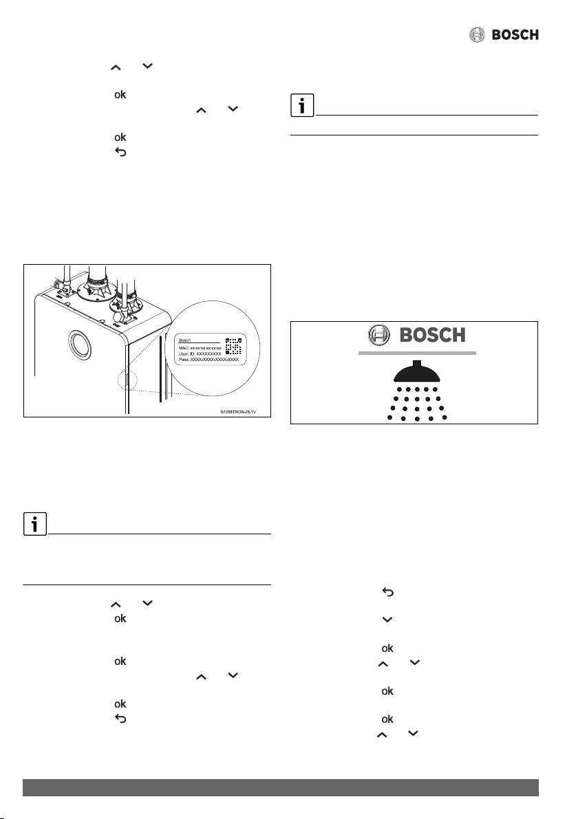
Operation instructions
Greentherm T9900 SE/i – 6 720 813 635 (2022/01)
56
▶ Use the symbols or to select the letters and
symbols from the list.
▶ Touch the symbol , to confirm each letter or symbol.
▶ To save the password use the symbols or to
select END.
▶Touch the symbol .
▶ Touch the symbol to return to main menu.
Display shows temperature value.
Appliance is connected to a network.
▶Download the “Bosch Water” app, available for Android and
IOS for communication with the water heater, see fig. 52.
▶ Open the app and follow the instructions.
▶ Use the smartphone to scan the QR code located on the
right side of front cover.
Fig. 51 Data login label (QR code)
▶ Define a User password in the Bosch Water app.
Wi-Fi module is activated.
How to configure Hotspot menu in the appliance,
HT Hotspot
HT Hotspot menu is not displayed in the HMI if the appliance is
connected to a network (SC Scan).
▶Use RW Reset Wi-Fi menu to reset Wi-Fi connections.
▶ Use the symbols or to select HT Hotspot.
▶Touch the symbol .
Define password with more than 8 characters.
▶ Choose the letters and symbols from the list.
▶ Touch the symbol , to confirm each letter or symbol.
▶ To save the password use the symbols or to
select END.
▶Touch the symbol .
▶ Touch the symbol to return to main menu.
Display shows temperature value.
HT Hotspot option is defined.
▶Download the “Bosch Water” app, available for Android and
IOS for communication with the water heater, see fig. 52.
Do not open the Bosch Water app.
▶ In the smartphone, go to;
Settings > Wireless and Networks> Wi-Fi.
▶ Select the network named “waterheater-xxxxxx”, where
“xxxxxx” is the last 6 digits of the “MAC” address.
▶ Write the same password you defined in HT Hotspot menu.
▶ Open the app and follow the instructions.
▶ Use the smartphone to scan the QR code located on the left
side of front cover.
▶ Define a User password in the Bosch Water app.
Wi-Fi module is activated.
Bosch Water app
Fig. 52 Bosch Water APP
6.9.2 Wi-Fi options
After connecting the appliance to a network, the only available
menus in A7 Wireless Connectivity will be the following:
• ST Status
• DI Disconnect
• RE Reset
• MA MAC Address
• IP IP Address
How to access the Wi-Fi options:
▶ Touch the symbol .
Display shows P4 Information.
▶ Touch the symbol until the display shows SA
Settings.
▶ Touch the symbol .
▶ Use the symbols or to choose A7 Wireless
Connectivity.
▶ Touch the symbol .
Display shows Wi-Fi,
▶ Touch the symbol .
▶ Use the symbols or to select one option from the
list.
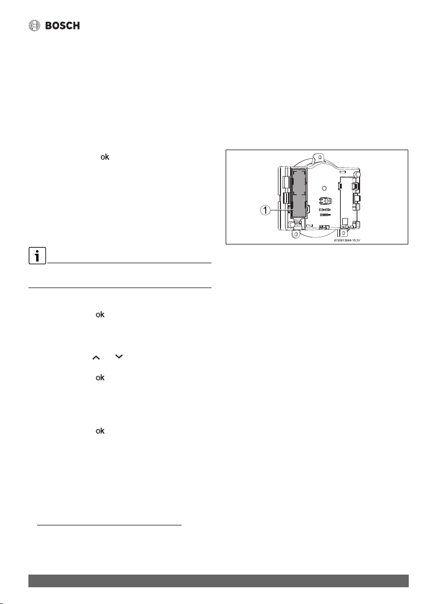
Operation instructions
57
Greentherm T9900 SE/i – 6 720 813 635 (2022/01)
ST Status
Display shows the status of wireless connection:
• connected
• disconnected
•hotspot
If HMI is connected to a wifi network, display shows the wireless
connection name.
DI Disconnect
▶ Choose DI Disconnect.
▶ Choose the symbol .
Display shows, Are you sure?
– Yes
– No
▶Choose Yes.
A green check mark is displayed indicating that the
appliance is disconnected from the network.
RE Reset
Choose this option to reset all Wi-Fi connection parameters or
User password defined in the Bosch Water app.
▶Choose RE Reset.
▶Touch the symbol .
Display shows,
– RW Reset Wi-Fi
1)
– RU Reset User Passwords
2)
▶ Use the symbols or to select one option from the
list.
▶Touch the symbol .
Display shows,
– Yes
– No
If choose Yes,
▶Touch the symbol .
A green check mark is displayed indicating that reset is
complete.
6.9.3 Problem solving to activate Wi-Fi
Exceed Wi-Fi activation time
The Wi-Fi module must be activated within 60 minutes after
plug in the appliance to the power supply.
▶ Unplug the appliance from the power supply.
▶ Repeat Wi-Fi activation process, see section 6.9.1 "Wi-Fi
activation".
Wi-Fi module disconnected from HMI
If an error message is displayed or isn’t possible to configure
Wi-Fi menus:
▶ Unplug the appliance from the power supply.
▶ Remove the front cover, see fig. 3, page 12.
▶ Confirm that Wi-Fi module is correctly installed in the HMI.
Wi-Fi module is located on the back side of HMI.
Fig. 53 Wi-Fi module installed in HMI
[1] Wi-Fi module
1) Reset all Wi-Fi network connections.
2) Reset User password defined in the Bosch Water app.
Maintenance and service
Greentherm T9900 SE/i – 6 720 813 635 (2022/01)
58
7 Maintenance and service
DANGER:
▶ Always shut off the electrical power supply, shut off the
manual gas valve and shut off the water valves before
servicing.
DANGER:
Risk of explosion!
▶ Replace all dismantled seals and o-rings with new ones.
NOTICE:
▶ Inspect the complete water heating system once a year.
▶ Follow points 5 and 6 in Table 24 after 400 operation
hours or 25000 cycles (whichever occurs first), see
chapter 6.5.1(Data History).
▶ Inspect the water heater and components for wear or
fatigue. Immediately repair all faults to avoid damage to the
system.
Table 24 Annual maintenance
7.1 Required annual maintenance
(To remove front cover, see page 12)
WARNING:
Maintenance must be done by a qualified contractor.
Venting System
NOTICE:
Venting system blocked!
▶ For horizontally vented appliances, keep the area around
the venting system free of snow or ice to prevent blockage.
• Venting system - Inspect inside of flue pipe and remove any
blockage or restriction. Observe burner flames during
heater operation (front cover must be removed). Burner
flames should be steady and blue. Yellow, inconsistent
(bouncing) flames may be an indication of poor ventilation
or combustion air supply. Inspect the combustion air intake
pipe and remove any blockage or debris. Inspect air intake
and exhaust terminations and remove any blockage or
debris.
Heat Exchanger
• Inspect burner observation window for cracks or spillage of
flue gases. Observe burner flames during heater operation.
Flames should be steady and blue with no signs of
yellowing. Yellow burner flames are an indication of
improper combustion. Refer to section 4.6 to verify the
exhaust system and combustion air supply meets the
manufacturer's specifications.
Pressure Relief
• Manually open the pressure relief valve to ensure proper
operation, make sure discharge drains away safely.
Inlet Water Filter
• Verify the inlet water filter screen is clean and undamaged.
The inlet water filter is located on the top of the appliance,
at the cold water inlet connection. (See Fig. 29, page 38).
Close the installer supplied water shutoff valve purge the
water using discharge drains and remove the brass hex cap
holding filter. Remove the filter, clean and/ or replace if
damaged.
Descaling
• In areas where the water supply has a high mineral content
(see table 17 Water Quality) the heat exchanger should be
flushed with a descaling solution. Scale build up will
Required Annual Maintenance Table
Every year
1. Inspect venting system X
2. Inspect heat exchanger X
3. Inspect burner X
1)
1) Proceed with air filter cleaning or replacement if error code
CE, CF and C2 is displayed. Check the flue exhaust for
blockage (appliance is protected against flue blockage).
4. Inspect pressure relief X
5. Inspect water filter X
6. Heat Exchanger Descaling X
2)
2) Proceed with heat exchanger descaling whenever error
codes AA and E5 are displayed (appliance is protected
against over heating in case of scaling), see table 17 Water
Quality.
7. Inspect condensate trap X
8. Inspect air filter X
1)
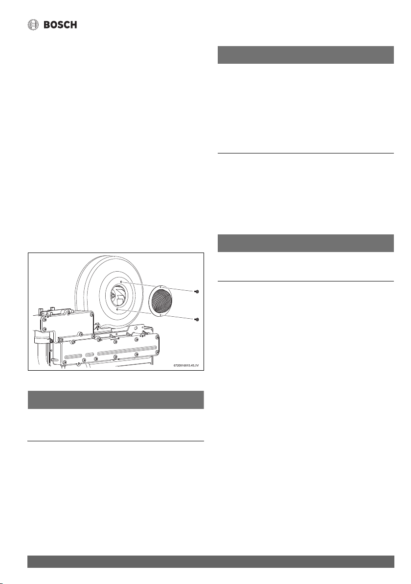
Maintenance and service
59
Greentherm T9900 SE/i – 6 720 813 635 (2022/01)
shorten the life of the water heater and damage resulting
from scale is not covered under warranty. Refer to section
7.3 for detailed instructions on descaling the heat
exchanger.
Condensate Siphon
• Check for debris and clean if needed.
Air Filter
• Verify if the air filter is clean and undamaged.
The air filter is attached to the fan assembly, see fig. 54.
• Air filter must be cleaned or replaced in case it is clogged or
damaged.
How to remove/assembly air filter
▶ Disconnect the electrical supply from the water heater.
▶ Remove appliance front cover, see page 12.
▶ Remove cover from the air filter.
▶ Loosen two philips head screws.
▶ Remove air filter from the fan.
▶ Proceed in the reverse order for assembly.
Fig. 54 Remove/assembly air filter
NOTICE:
Appliance malfunction!
▶ Air filter should not be removed during appliance normal
operation as, as it may increase the risk of burner blockage.
NOTICE:
Risk of burner blockage!
▶ Optional paper filter (part # 8738725270) can be
installed on the air fan for increased protection against
dusty, dirty combustion air or heavy pollen entering the
combustion chamber to reduce the risk of burner blockage.
In areas with high solid particles content in the air it is
recommended to use this filter. Maintenance frequency
might need to be adjusted to keep the filter clean and allow
a good performance of the heater.
7.2 Winterizing for seasonal use
The water heater must not be installed in a location where it
may be exposed to freezing temperatures unless connected to
electrical power. All water must be drained from the heater in
order to avoid damage to the unit from exposure to freezing
temperatures.
NOTICE:
Use of agents such as anti-freeze is not permitted and voids the
warranty, as they may cause damage to the water heater's
internal components.
1. Hold ON/OFF switch on the water heater for 3 secs. to turn
OFF the heater and unplug the power supply cord. The
display should be blank.
2. Shut off the gas supply to the water heater.
3. Shut off the water supply to the water heater using installer
supplied shutoff valve.
4. Open hot water faucets to drain and relieve pressure from
the plumbing system. If water continues to flow after 5
minutes, a crossover of the hot and cold water pipes is
present and must be corrected before proceeding.
5. Disconnect the inlet and outlet water pipes from the water
heater. Place a small bucket underneath the water heater to
catch residual water remaining inside the water heater.
6. Using an air compressor, blow short bursts of air (50psi
max) through the inlet water connection or inlet water filter
until there is no water present coming through the outlet
water connection of the heater.
7. Empty condensate trap.
8. Reconnect the water fittings and return the heater to
service when danger of freezing has passed.
7.3 Mineral scale build-up
Periodic descaling may be necessary in areas with high mineral
content in the water (See table 17 Water Quality). Scale
buildup in the heat exchanger may result in lower flow rates,
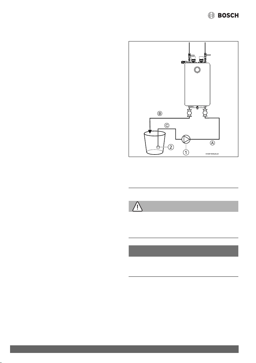
Troubleshooting
Greentherm T9900 SE/i – 6 720 813 635 (2022/01)
60
error codes of AA, E3, A5 and boiling sounds in the heat
exchanger.
A water softener is required if the water hardness exceeds 12
grains/gal (200 mg/l) calcium carbonate. Damage to the water
heater resulting from hard water/scale deposits will not be
covered under warranty.
Descaling using a pump
▶ Disconnect the electrical supply from the water heater.
▶ Shut off the water supply to the water heater.
▶ Open hot water faucets to drain and relieve pressure from
the plumbing system.
▶ Shut off hot water valve to the water heater.
▶ Remove the caps from both inlet and outlet drain
connections.
▶ Connect a line (A) from the outlet of the circulating pump
(installer supplied) to the inlet drain connection on the
water heater (see fig. 55.)
▶ Using another line (B), connect the outlet drain connection
on the water heater. Route the other end of this line into a
descaling reservoir.
▶ Using a 3rd line (C) from the descaling reservoir, connect to
the inlet side of circulating pump. Install a filter on the end
of the line in the descaling reservoir.
▶ Make sure all connections are water tight.
▶ Fill the descaling reservoir with descaling solution so both
lines inside are submersed. We recommend a straight
white vinegar solution. If using a commercial descalant,
refer to manufacturer's instructions for proper dilution
ratio.
▶ Ensure both drain connections are open.
▶ Operate the circulating pump.
▶ Make sure there are no leaks and the solution is flowing
from the descaling reservoir through the heater and
returning to the reservoir.
▶ Run the solution through the heater until the solution
returning to the descaling reservoir comes out clear.
(Changing to a fresh solution may be necessary during this
process).
▶ Disconnect all lines and drain all solution from heat
exchanger. Properly discard the solution.
▶ Attach the cap to the inlet drain connection to close it.
▶ Position a container below the outlet drain connection and
connect the cold water supply. Open the cold water supply
shutoff valve and flush the heat exchanger with clean water.
▶ Close the cold water shutoff valve and reconnect hot water
supply to the water heater.
▶ Attach the cap to the outlet drain connection to close it.
▶ Reconnect the electrical supply to the unit, open the water
shutoff valves, and return the unit to service.
Fig. 55
[1] Pump
[2] Water filter
8Troubleshooting
WARNING:
▶ If you are unable to perform the tasks listed below, or need
additional assistance please contact a service provider or
contractor.
NOTICE:
In some areas local code may require that the tasks described
in this section must be performed by a certified contractor.
▶ Please check your local codes to ensure compliance.
8.1 Introduction
Many of the questions customers ask regarding operation of
this unit can be answered by following the troubleshooting
steps as outlined below. For best results, perform each step
before proceeding to the next. The suggested solutions may
require that the cover be taken off (see fig. 3, page 12).

Troubleshooting
61
Greentherm T9900 SE/i – 6 720 813 635 (2022/01)
8.2 Burner does not ignite when a hot water
faucet is opened
It is recommended to use “P4 Information” page 48, chapter
6.5.1 as a tool for problem solving.
1. If the display is blank, verify power at the outlet. (120VAC/
60Hz properly grounded circuit required). Confirm power
to the heater. Check all wire connections including plugged
connectors.
2. Verify the fuse in the control board is good. To access the
fuse, the control board must be removed. See chapter 5.2,
page 45.
3. Make sure cold water inlet connection is plumbed to the
right side of the heater when facing unit. See fig. 28,
page 38.
4. A minimum of 0.45 gallons per minute (1.7 l/m) of hot
water demand is required to activate the heater. Confirm at
least 0.4 gpm flow by timing how long it takes to fill a
container. A quart container should fill in 20 seconds or
less, from the hot water faucet only. Gradually increase
water flow (hot water demand) through the heater to
determine if the heater activates with higher flow.
5. Clean the inlet water filter screen per chapter 4.10,
page 37.
6. Inspect the water path for obstructions. Make sure all
shower heads, faucet aerators and whole house filters are
clear of debris.
7. Check for a plumbing crossover. A crossover in the hot and
cold plumbing pipes creates back pressure on the water
flowing through the heater. Therefore, a higher flow rate
than normal is needed to force the heater to activate. To
check for a plumbing crossover, shut off the cold water
supply to the water heater. Then open all of the hot water
faucets served by the water heater. Wait 10 minutes and
check for water flow at each faucet. There should be no
water flowing. Any continuous flow of water, small or large,
indicates a crossover is present and must be corrected.
Consult a professional plumber for help in correcting a
crossover. Failing single lever faucet mixing valves are
common causes of plumbing crossovers.
8. With the water heater's power supply cord unplugged,
remove the unit's front cover (See fig. 3, page 12). Check
all wire connections between the water valve, control unit
and electrode set ( fig. 67, page 74).
9. Check all wire connections between the water valve/water
flow sensor, control unit and electrode set. See chapter 10,
page 74.
8.3 Water is too hot
1. Selected temperature on the unit is too high. To lower
output temperature, see chapter 6.4, page 46.
2. Confirm the heater's gas type coincides with the type of gas
being supplied. See fig. 2, page 12 for location of rating
plate.
8.4 Water is not hot enough
1. Selected temperature on the unit is too low. To raise output
temperature, see chapter 6.4, page 46.
2. Confirm the heater's gas type coincides with the type of gas
being supplied. See fig. 2, page 12 for location of rating
plate.
3. Verify gas pressure is in accordance with specifications in
chapter 4.13, page 44. A gas pressure reading is needed
to proceed further. Contact your original installer or a local
certified gas technician to obtain this reading.
4. Check inlet gas particle screen/filter for blockage at inlet
gas valve. Need to remove gas valve from the appliance.
5. Cold water is mixing into the hot water lines (plumbing
crossover). A plumbing crossover can unintentionally mix
cold water with the hot water leaving the heater. The end
result is a cooler water temperature than desired. To check
for a plumbing crossover, shut off the cold water supply to
the water heater. Then open all of the hot water faucets
served by the heater. Wait 10 minutes and check all faucets
for water flow. There should be no water flowing. Any
continuous flow of water, small or large, indicates a
crossover and must be corrected. Consult a professional
plumber for help in correcting a crossover. Failing single
lever faucet mixing valves are common causes of plumbing
crossovers.
8.5 Low water flow/pressure
1. Too many hot water applications are being used
simultaneously or too much flow is demanded. The water
heater will effectively support two 2.0-2.5 GPM shower
heads simultaneously or multiple sink applications. Greater
draws will result in a water pressure drop and reduced flow
at faucets.
2. If the selected temperature on the unit is set too high for the
demanded flow rate, the water heater will close its
motorized water valve, reducing the hot water flow rate in
an attempt to reach the selected output temperature.
Lowering the selected temperature will allow the motorized
water valve to open up for increased water flow rate.
3. Clean inlet filter screen as instructed in chapter 7.1,
page 58 to increase flow through the heater.
4. Inspect the water path for obstructions. Make sure all
shower heads, faucet aerators and whole house filters are
clear of debris. It may be necessary to upgrade to higher
flow rate shower heads if allowed by local code.

Troubleshooting
Greentherm T9900 SE/i – 6 720 813 635 (2022/01)
62
5. In areas where the water has a high mineral content,
periodic descaling may necessary. See chapter 7.3,
page 59 for directions.
8.6 Hot water temperature fluctuates at faucet
1. If the water heater set point temperature is high, mixing at
the faucet could deactivate the water heater. The addition
of too much cold will overpower hot water flow from the
tankless water heater reducing its flow below the activation
point.
If this slows the flow through the tankless water heater
below its activation point, it will shut off the burner.
2. Unbalanced pressure in water lines. Any restriction in the
water heater, such as a clogged inlet water filter screen, can
result in unequal pressures between the cold and hot water
lines. In such cases, when mixing in the higher pressure
cold water at the faucet, the lower pressure hot water can
be overpowered. This will shut down the burners because
the hot water flow rate falls below the minimum flow rate
required for activation. Verify that the inlet water filter
screen is clean and clear of debris. See chapter 7.1,
page 58 for inlet water filter cleaning instructions.
3. The water heater may be deactivated by temperature
balancing shower valves. If the water heater's set point
temperature is set too high, the temperature balance
shower valve will automatically mix in cold water to reduce
the hot water temperature. An adjustment should be made
to minimize the amount of cold water the valve is adding.
Additionally, the temperature setting on the water heater
can be lowered to reduce the amount of cold water that the
temperature balance valve mixes in.
4. Inlet water pressure is erratic due to fluctuating supply
water pressure. For installation on a private well system
with the use of a pressure tank, the lowest pressure range
setting recommended is 30 - 45 psi (2.06 - 3.1 bar).
Consult your installer or local plumber for effective ways to
maintain constant water pressure to the appliance when on
a well system.
8.7 Noisy burner/heater during operation
Burner noises can be heard if combustion is not properly set.
This could be caused by improper gas supply conditions (gas
pressure and/or gas composition).
Two types of noise can be heard: low pitch noise/vibration
(rumbling) and high pitch noise/vibration (whistling).
8.7.1 High pitch noise
1. Verify if correct gas type is selected (see section 6.8).
2. Verify is gas pressure is within specified range (see
section 3.2).
3. Ensure that the venting used is according to specifications
(see section 4.6) and cross contamination does not exist.
Ensure that intake and exhaust terminations maintain
required clearances.
If gas type is properly selected, gas pressure is within
range, the venting is according to specifications, and the
problem persists:
4. Perform the gas and air adjustment as described in
section 8.12.
8.7.2 Low pitch noise
1. Verify if correct gas type is selected (see section 6.8).
2. Verify if gas pressure is within specified range (see
section 3.2).
If gas type is properly selected, gas pressure is within
range, the venting is according to specifications, and the
problem persists:
3. Perform the gas and air adjustment as described in
section 8.12.
8.8 Error codes C1, C2, CF and/or CE
C1, C2, CF and CE errors could be caused by a too long flue
and/or an obstruction in the venting.
1. Verify if there are any venting obstructions and remove
them if that is the case.
2. Ensure that the venting used is according to specifications
(see section 4.6).
3. Reset the error by holding the On/Off button for 3s.
If there are no obstructions and venting is according to
specifications, and the problem persists:
4. Perform the gas and air adjustment as described in
section 8.12.
8.9 Error codes EA and/or EC
EA and EC errors can appear if combustion is not properly set.
This could be caused by improper gas supply conditions (gas
pressure and/or gas composition).
1. Verify if correct gas type is selected (see section 6.8).
2. Verify is gas pressure is within specified range (see
section 3.2).
If gas type is properly selected, gas pressure is within
range, the venting is according to specifications, and the
problem persists:
3. Perform the gas and air adjustment as described in
section 8.12.
8.10 Internal recirculation pump
1. Pump makes noise. Purge the recirculation water circuit.
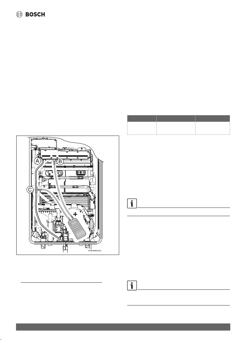
Troubleshooting
63
Greentherm T9900 SE/i – 6 720 813 635 (2022/01)
2. How to verify the recirculation flow. Close all water faucets,
access to information menu, P4 information > Operation
Data, choose the option Flow.
The value should be above 1 GPM (4 l/min).
3. If the appliance doesn’t make the recirculation. Confirm if
recirculation mode is active, inspect the recirculation
circuit and water filter for any obstructions, ensure that the
recirculation circuit is fill with water, verify if the
recirculation circuit is below the maximum pipe length, see
table 18.
8.11 Manifold gas pressure
The manifold gas pressure measurement is only carried out if it
is necessary to confirm the value from the rating plate.
In case of a high deviation between measured and stated
values, please proceed with Gas/air adjustment (see
section 8.12)
1)
.
▶ Turn Off the appliance.
▶ Remove the front cover of the appliance (see page 12).
Fig. 56 Pressure head points
[A] Air pressure head in the box
[B] Gas pressure head in the burner
[C] Tee (installer supplied)
▶ Loosen the set screw of the pressure head point [B].
▶ Connect the pressure gauge connection "+" to the test
point [B].
▶ Connect the pressure gauge "-" to the pressure head point
[A] using the accessory [C].
▶ Turn On the appliance.
▶ Position the front cover near the appliance and make sure
the cable for the display is connected.
▶ Open all hot water faucets to achieve a flow rate of at least
6 gallons per minute. (1 tub and 2 sinks should be
sufficient). If heater goes back to P2, open more hot water
fixtures to allow sufficient flow and access to P1 menu.
▶ Record the manifold gas pressure reading in table 25.
Manifold gas pressure refers to the relative pressure
between gas manifold nozzles inlet and outlet [A]-[B].
Table 25
▶ Turn Off the appliance.
▶ Disconnect the pressure gauges from the pressure heads
points [A] and [B].
▶ Tighten the shutter screws of the pressure heads points [A]
and [B].
▶ Reassemble the front cover onto he appliance.
▶ Turn ON the appliance to return to normal operation.
8.12 Gas and Air Adjustment
Appliance is pre-adjusted from factory.
Gas/Air adjustments are only required when;
• The appliance is converted to LPG ( section 6.8).
• The appliance shows repeated unresolved errors (
chapter 9).
• After the replacement of the electronic control unit, fan or
gas valve.
The gas and air adjustment can be completed in two ways:
•Automatic <UC - Auto Adjust> ( section 8.12.1).
• Manually <MA - Manual Adjust> ( section 8.12.2).
Improper gas pressure will affect combustion.
▶ Please see chapter 4.13 for more information.
1) Manifold gas pressure from the rating plate is valid for sea
level operation with standard gas pressure and
composition. If operating conditions are different from
those, values from section 8.12 should prevail over
manifold gas pressure to assure a correct appliance tuning.
Value Date
Manifold gas
pressure
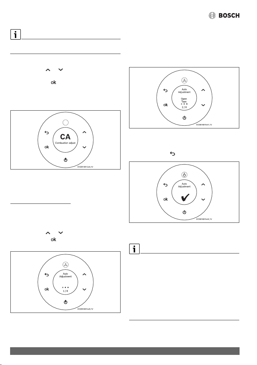
Troubleshooting
Greentherm T9900 SE/i – 6 720 813 635 (2022/01)
64
Access to CA Combustion Adjust menu is only possible after
accessing to AU Technical Settings menu ( section 6.6).
After enter AU Technical Settings menu,
▶ Touch symbols or to select CA menu.
Display shows CA Combustion Adjust.
▶ Touch the symbol to enter CA menu.
• UC - Auto Adjust
• MA - Manual Adjust
• ...
Fig. 57 CA Combustion Adjust
8.12.1 Automatic Gas and Air adjustment
The UC Auto Adjust is the automatic Gas and Air adjustment
process. This process takes approximately 15 minutes, and
does not requires any intervention
besides insuring that
enough water flow is provided to the appliance.
To perform UC Auto Adjust of Gas/Air flow;
After enter CA Combustion Settings menu,
▶ Touch symbols or to select UC menu.
▶ Touch the symbol to enter UC menu.
Automatic adjustment has initiated.
Fig. 58 Auto Adjustment
▶ Open hot water taps when the display shows Open Taps.
This message will appear approximately 5 minutes after
initiate the automatic adjustment.
The appliance will display Open Taps whenever more flow
is required to continue the automatic adjustment process
(1 tub and 2 sinks are usually sufficient).
Fig. 59 Auto Adjust - Open Taps
▶ Wait until a green check mark is displayed indicating the
successful conclusion of the automatic adjustment.
▶ Touch the symbol to exit UC menu.
Fig. 60 Auto Adjust complete
Gas and Air auto adjustment is complete.
In case of failure in the auto calibration process verify if:
▶ Gas type and pressure are correct ( section 4.13).
▶ Vent length is according to specification ( section 4.6).
▶ Wind conditions are stable (e.g. wind gusts may be a cause
of failure).
▶ Hot water flow is sufficient and stable (e.g. water from a
well is a potential source of water instability).
In case of positive results for all these actions:
▶ Perform manual adjustment according to chapter 8.12.2
or contact Bosch support line for further assistance.
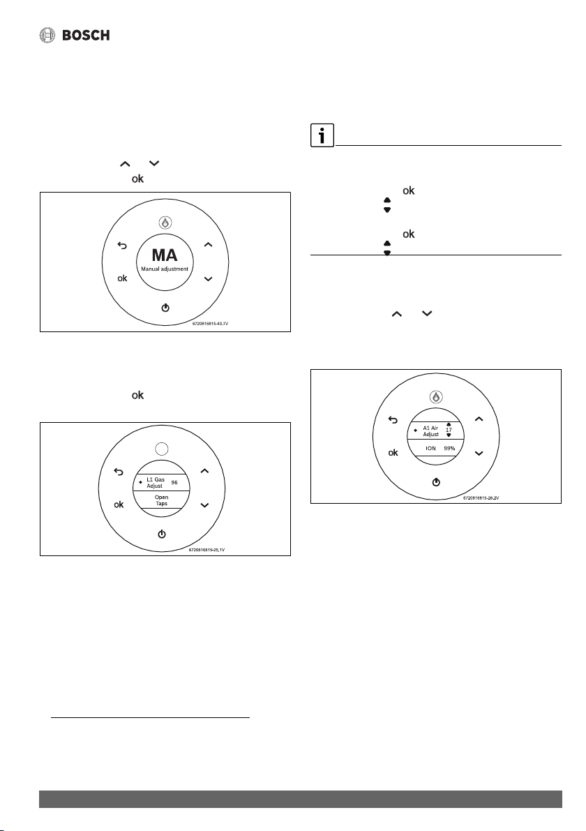
Troubleshooting
65
Greentherm T9900 SE/i – 6 720 813 635 (2022/01)
8.12.2 Manual Gas and Air Adjustment
Gas and Air adjustment is also possible to perform manually.
This is only recommended if the automatic adjustment process
is not possible to complete successfully.
To perform MA Manual Adjust of Gas/Air flow;
▶ After enter CA Combustion Adjust menu,
▶ Touch symbols or to select MA menu.
▶ Touch the symbol to enter MA menu.
Fig. 61 Manual Adjust - MA
Access P1 menu (maximum power)
L1 Gas Adjust
▶ Touch the symbol to enter P1 menu.
Display shows L1 Gas Adjust.
Fig. 62 L1 Gas Adjust - Open Taps
▶ Open hot water taps when the display shows Open Taps.
The appliance will display Open Taps whenever more flow
is required to continue the automatic adjustment process
(1 tub and 2 sinks are usually sufficient).
Display shows Output Power (%) when there is enough
water flow.
1)
▶Change L1 Gas Adjust parameter until power reaches
100% ± 2%
▶Increase L1 Gas Adjust parameter to increase output
power, and vice-versa.
How to enter a new tuning parameter (i.e. L1, L2, A1, A2).
▶ Select the desired parameter.
▶ Touch the symbol .
The symbols appears in the display.
▶ Change to the desired value.
▶ Touch the symbol when finished.
The symbols disappear.
▶ L1 Gas Adjust is now complete.
A1 Air Adjust
▶ Touch symbols or until display shows A1 Air
Adjust - ION.
▶Change A1 Air Adjust parameter until ION ratio reaches
100% ± 2%.
Fig. 63 A1 Air Adjust - ION
▶Increase A1 Air Adjust parameter to increase ION ratio and
vice-versa.
A1 Air Adjust is now complete.
1) More flow may be required if inlet water temperature is
high, i.e. applications with waste water recovery system,
preheated solar water.
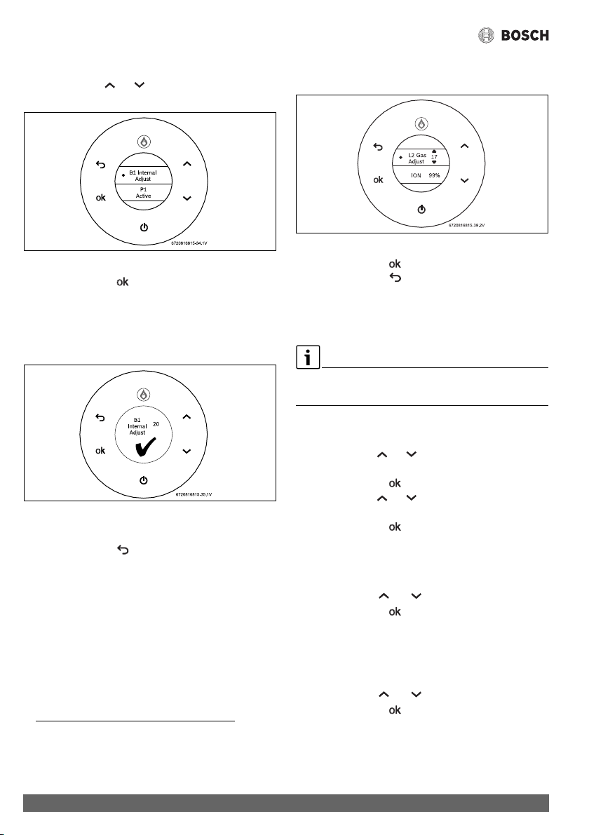
Troubleshooting
Greentherm T9900 SE/i – 6 720 813 635 (2022/01)
66
B1 Internal Adjust
▶ Touch symbols or until display shows B1 Internal
Adjust.
Fig. 64 B1 Internal Adjust - P1 Active
▶ Touch the symbol to enter B1 Internal Adjust.
1)
B1 Internal Adjust will start automatically.
▶ Wait approximately 60 seconds until a green check mark
appears in the display, which indicates that the B1 Internal
Adjust is completed. Do not interfere with the appliance
during this period.
Fig. 65 B1 Internal adjust is completed
L2 Gas Adjust
▶ Touch the symbol to enter L2 Gas Adjust.
L2 Gas Adjust value is shown (ionization).
▶Change L2 Gas Adjust parameter until ratio reaches 100%
±2%.
▶Increase L2 Gas Adjust parameter to increase ION ratio
and vice-versa.
Fig. 66 L2 Gas Adjust - ION ratio
▶ Touch the symbol to save value.
▶ Touch the symbol to return to the main menu.
Minimum power adjust is completed.
Gas and Air adjustment is complete.
8.12.3 Restore factory values
To restore factory values for combustion settings,
▶ Proceed with the following steps.
To enter P1 and P2 menu,
▶ Access to AU Technical Settings menu.
▶ Touch symbols or to select CA menu.
Display shows CA Combustion Adjust.
▶ Touch the symbol to enter CA menu.
▶ Touch symbols or to select MA - Manual Adjust
menu.
▶ Touch the symbol to enter P1 or P2 menu.
Reset Parameters P1
After enter MA - Manual Adjust,
▶ Access to menu P1.
▶ Touch symbols or to select Reset Parameters.
▶ Touch the symbol .
The factory default values for P1 are restored.
Reset Parameters P2
After enter MA - Manual Adjust,
▶ Access to menu P2.
▶ Touch symbols or to select Reset Parameters.
▶ Touch the symbol .
The factory default values for P2 are restored.
1) B1 Internal Adjust will calculate automatically the amount
of air in low fire (P2). This method uses P1 values to start
calculation.
Troubleshooting
67
Greentherm T9900 SE/i – 6 720 813 635 (2022/01)
8.12.4 Additional combustion settings
The parameters and operation modes presented in this section
are available for certification purposes and advanced
troubleshooting with guidance from BOSCH support line.
For optimal operation, use the default settings.
IC - Ionization control
Default setting is On.
▶ Only a qualified technician can change this parameter.
PD Power derate
Default setting is On.
▶ Only a qualified technician can change this parameter.
Minimum power and check (P2)
▶ Only a qualified technician can change this parameter.
PP P2A2
Default setting is On.
▶ Only a qualified technician can change this parameter.
P1 Max. Power - Ionization control
Default setting is Off.
▶ Only a qualified technician can change this parameter.
P0 Min. Power - Ionization control
Default setting is Off.
▶ Only a qualified technician can change this parameter.
Problem solving
Greentherm T9900 SE/i – 6 720 813 635 (2022/01)
68
9Problem solving
9.1 Error code diagnostics
To remove error codes from the display,
▶ Touch the On/Off button more than 3 sec. (long press).
Installation, maintenance and repair must only be carried out
by qualified contractors. The following table describes the
solutions for possible problems.
Display Description Solution
A0 Water temperature sensors [17] [19] [20]
disconnected or damaged.
▶ Check sensor wire connections.
1)
2)
▶ Replace the sensor and/or wire connections, if the
problem persists.
1)
A1 Air temperature inside the cabinet [18] is above
158 °F (70 °C). Appliance regulates power to
protect against overheat.
▶ External air temperature is above 140 °F (60 °C).
▶ Check for flue leakages inside the appliance or in
concentric vent.
1)
A2 External water temperature sensor/aquastat [21]
disconnected, damaged or not properly installed.
▶ Check temperature sensor and associated
connections.
1)
2)
▶ Check sensor position in the tank well.
▶ Verify if correct recirculation settings are selected
(section 6.5.2).
▶ Replace the sensor and/or wire connections, if the
problem persists.
1)
A3 Flue gases temperature sensor [15] disconnected
or damaged.
▶ Check sensor wire connections.
1)
2)
▶ Replace the sensor and/or wire connections, if the
problem persists.
1)
A4 Air temperature sensor [18] disconnected or
damaged.
▶ Check sensor wire connections.
1)
2)
▶ Replace the sensor and/or wire connections, if the
problem persists.
1)
A5 Condensing unit flue temperature sensor [16]
disconnected or damaged.
▶ Check sensor wire connections.
1)
2)
▶ Replace the sensor and/or wire connections, if the
problem persists.
1)
A6 Inlet cold water temperature sensor [20]
disconnected or damaged.
▶ Check sensor wire connections.
1)
2)
▶ Replace the sensor and/or wire connections, if the
problem persists.
1)
A7 Heat exchanger hot water temperature sensor [16]
disconnected or damaged.
▶ Check sensor wire connections.
1)
2)
▶ Replace the sensor and/or wire connections, if the
problem persists.
1)
A8 Outlet hot water temperature sensor [17]
disconnected or damaged.
▶ Check connections or replace sensor.
1)
2)
▶ Replace the sensor and/or wire connections, if the
problem persists.
1)
A9
3)
Incorrect output power (too low). ▶ Check gas inlet pressure
1)
( section 4.13).
▶ Check water temperature sensors [17][19][20]
and water flow sensor [14] wire connections.
▶ Check connections or replace sensor (
section 11), replace any if it is not according to
specification.
1)
2)
Problem solving
69
Greentherm T9900 SE/i – 6 720 813 635 (2022/01)
AA
3)
Condensing unit flue gases temperature [16]
above 392 °F (200 °C) and/or flue gases
temperature [15] above 145 °F (63 °C) at the
exhaust sensor [15]. Appliance regulates power to
protect against overheating.
▶ Check flue gas temperature sensor.
▶ Check water inlet temperature sensor.
▶ Descale appliance ( section 7.3).
1)
AD Flue blockage detected during startup due to
insufficient combustion air. Appliance power
derate and possible reduction of comfort level.
▶ Reset error (press and hold on/off button for 3
seconds).
If the problem persists:
▶ Check air openings and exhaust opening for
obstructions and reset the error.
▶ Check if flue length is according to specification
(section 4.6) and reset the error.
▶ Check if the air filter is dirty or clogged, replace it if
needed.
▶ Perform gas and air tuning ( section 8.12).
1)
BB Fan calibration triggered due to missed ignitions. ▶ Check gas inlet pressure ( section 4.13).
1)
▶ Perform gas and air tuning ( section 8.12).
1)
BC Successive fan calibration with similar learned
values.
▶ Check gas inlet pressure ( section 4.13).
1)
▶ Perform gas and air tuning ( section 8.12).
1)
C1
4)
C2
4)
Excessive flue blockage detected during startup
due to insufficient combustion air.
Appliance shuts down for safety
▶ Reset error (touch and hold on/off button for 3
seconds).
If the problem persists:
▶ Check air intake and exhaust pipes and terminals for
obstructions and reset the error.
▶ Check if flue length is according to specification
(section 4.6) and reset the error.
▶ Check if the air filter is dirty or clogged, replace it if
needed.
▶ Perform gas and air tuning ( section 8.12).
1)
C3 Flow sensor [14] does not detect water
recirculation.
▶ Check pump and connections.
1)
▶ Check recirculation circuit for any blockage.
C5 Bypass water valve [8] disconnected or damaged. ▶ Check bypass water valve wire connections.
1)
If the problem persists:
▶ Replace the bypass water valve and/or wire
connections. After valve replacement, proceed with
bypass water valve calibration (section 6.7).
1)
C7 Fan [2] disconnected or damaged. ▶ Check fan wire connections.
▶ Reset error (touch and hold on/off button for 3
seconds)
If the problem persists:
▶ Replace the fan and/or wire connections.
1)
C8 Main water valve [22] disconnected or damaged. ▶ Check main water valve wire connections.
1)
▶ Proceed with main water valve calibration.
If the problem persists:
▶ Replace main water valve and/or wire connections.
After valve replacement, proceed with main water
valve calibration (section 6.7).
1)
Display Description Solution
Problem solving
Greentherm T9900 SE/i – 6 720 813 635 (2022/01)
70
C9 Barometric pressure sensor damaged. ▶ Reset error (touch and hold on/off button for 3
seconds).
If the problem persists:
▶ Replace electronic control unit (ECU).
1)
CA Water flow above 9.2gpm. ▶ Disconnect the appliance and purge hydraulic circuit
to remove air.
1)
▶ Install water flow restrictor.
1)
▶ Check water pressure does not exceed 150psi
(section 3.2).
CE
4)
Excessive flue blockage detected during operation
due to excessive pressure on the siphon.
Appliance shuts down for safety.
▶ Reset error (touch and hold on/off button for 3
seconds).
If the problem persists:
▶ Check exhaust pipes and terminals for obstructions
and reset the error.
▶ Check if flue length is according to specification
(section 4.6) and reset the error.
▶ Check if the air filter is dirty or clogged, replace it if
needed.
▶ Perform gas and air tuning ( section 8.12).
1)
CF
4)
Excessive
flue blockage detected during operation
due to insufficient combustion air.
Appliance shuts down for safety.
▶ Reset error (touch and hold on/off button for 3
seconds).
If the problem persists:
▶ Check air intake and exhaust pipes and terminals for
obstructions and reset the error.
▶ Check if flue length is according to specification
(section 4.6) and reset the error.
▶ Check if the air filter is dirty or clogged, replace it if
needed.
▶ Perform gas and air tuning ( section 8.12).
1)
E0 Electronic control unit internal error. ▶ Reset error (touch and hold on/off button for 3
seconds).
If the problem persists:
▶ Replace electronic control unit.
1)
E1 Hot water temperature above 194 °F (90 °C).
Appliance burner cut off to prevent scalding and
reactivation after cooling down.
▶ Disconnect the appliance and purge hydraulic circuit
to remove air.
If the problem persists:
▶ Reduce setpoint temperature to minimize
temperature instabilities.
E3
4)
Flue gases temperature above 167 °F (75 °C)
(residential) or 2 minutes above 145 °F (63 °C).
Appliance burner cut off to prevent overheating.
▶ Descale appliance ( section 7.3).
1)
▶ Reset error (touch and hold on/off button for 3
seconds).
If the problem persists:
▶ Check sensor resistance [15] (section 11) and
replace the sensor if it is not according to
specification.
1)2)
Display Description Solution
Problem solving
71
Greentherm T9900 SE/i – 6 720 813 635 (2022/01)
E4 Air temperature inside cabinet above 176 °F
(80 °C) or 2 minutes above 158 °F (70 °C).
Appliance burner cut off to prevent overheating.
▶ Check for flue gas leakage inside the cabinet or
concentric vent.
1)
▶ Reset error (touch and hold on/off button for 3
seconds).
If the problem persists:
▶ Check sensor resistance [18] (section 11) and
replace the sensor if it is not according to
specification.
1)
2)
E5 Condensing unit flue gases temperature above
428 °F (220 °C) or 2 minutes above 392 °F
(200 °C).
Appliance burner cut off to prevent overheating.
▶ Descale appliance ( section 7.3).
1)
▶ Reset error (touch and hold on/off button for 3
seconds).
If the problem persists:
▶ Check sensor resistance [16] (section 11) and
replace the sensor if it is not according to
specification.
1)
2)
E7 Electronic control unit internal error. ▶ Reset error (touch and hold on/off button for 3
seconds).
If the problem persists:
▶ Replace electronic control unit.
1)
E8 Error during ionization test. Electronic control unit
internal error.
▶ Replace electronic control unit.
1)
E9 Thermal fuse [13] broken. ▶ Replace thermal fuse.
1)
EA
4)
Ignition failure. ▶ Check gas inlet pressure ( section 4.13).
1)
▶ Perform gas and air tuning ( section 8.12).
1)
EB Electronic control unit internal error. ▶ Reset error (touch and hold on/off button for 3
seconds).
If the problem persists:
▶ Replace electronic control unit.
1)
EC
4)
Flame lost during operation. ▶ Check gas inlet pressure ( section 4.13).
1)
▶ Perform gas and air tuning ( section 8.12).
1)
EE Gas valve modulation solenoid [7] disconnected. ▶ Check gas valve wire connection.
1)
If the problem persists:
▶ Replace the gas valve and/or wire connections and/
or electronic control unit. For gas valve replacement
perform gas and air tuning ( section 8.12).
1)
EF Wrong gas connected (LP instead of NG) for
current appliance configuration.
▶ Check gas type ( section 6.8).
1)
F2 Electronic control unit internal error. ▶ Reset error (touch and hold on/off button for 3
seconds).
If the problem persists:
▶ Replace electronic control unit.
1)
Display Description Solution
Problem solving
Greentherm T9900 SE/i – 6 720 813 635 (2022/01)
72
F3 Electronic control unit internal error. ▶ Reset error (touch and hold on/off button for 3
seconds).
If appliance’s configuration is required:
▶ See section 6.6 to configure appliance (region,
power, type and gas type) and perform an automatic
combustion adjustment according to the
section 8.12.
1)
If the problem persists:
▶ Replace electronic control unit.
1)
F7 Electronic control unit internal error. ▶ Reset error (touch and hold on/off button for 3
seconds).
If the problem persists:
▶ Replace electronic control unit.
1)
F8 Electronic control unit internal error. ▶ Reset error (touch and hold on/off button for 3
seconds).
If the problem persists:
▶ Replace electronic control unit.
1)
F9 Gas valve driver internal fault. ▶ Check gas valve wire connections.
1)
If the problem persists:
▶ Replace the wire connections and/or electronic
control unit.
1)
FA Gas leakage in the gas path (gas valve or gas
manifold shut-off valves).
▶ Replace the gas valve and/or gas manifold.
1)
▶ After gas valve and/or gas manifold replacement
perform gas and air tuning ( section 8.12).
1)
FC Touch screen key pressed for more than 20
seconds.
▶ Release the touch screen key.
▶ Clean the touch screen display.
Display reads
SOLAR but without
existence of solar
thermal system.
Display reads
SOLAR and water
temperature low.
Power demand lower than appliance minimum
output power.
▶ Increase hot water flow.
▶ increase setpoint temperature.
Display shows a red
X.
HMI (display) is not communicating with Electronic
Control Unit.
▶ Reset the appliance by unplugging it for some
seconds (at least 10) and plug it back in.
▶ Replace the HMI (display) and/or wire connections
and/or electronic control unit.
High pitch noise
(whistling)
Combustion flame with gas in excess or lack of air. ▶ Check if gas type is correct ( section 6.8).
1)
▶ Check gas inlet pressure ( section 4.13).
1)
▶ Perform gas and air tuning ( section 8.12).
1)
Low pitch noise
with vibration
(rumbling)
Combustion flame with air in excess or lack of gas. ▶ Check if gas type is correct ( section 6.8).
1)
▶ Check gas inlet pressure ( section 4.13).
1)
▶ Perform gas and air tuning ( section 8.12).
1)
1) only to be carried out by qualified contractors.
2) see temperature resistance charts in fig. 68 and 69.
3) Error reset also possible by shutting-off water flow to the unit, and turning it back on.
Display Description Solution

Problem solving
73
Greentherm T9900 SE/i – 6 720 813 635 (2022/01)
Table 26
Note: If the appliance is locked for safety reasons, information is shown on the display to give more information on the problem.
Once the problem is solved, you may have to reset the error (touch and hold button for 3 seconds). Error reset will only take
effect if error is visible on the display.
4) Error reset also possible by shutting-off water flow to the unit, and turning it back on, limited to 3 times per hour. It can take up
to 3 minutes for appliance initialization.
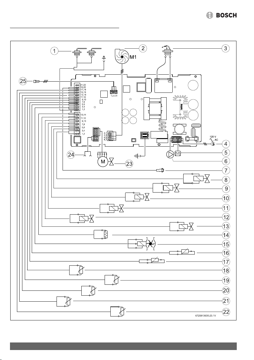
Electrical diagram
Greentherm T9900 SE/i – 6 720 813 635 (2022/01)
74
10 Electrical diagram
Fig. 67 Electrical diagram

Electrical diagram
75
Greentherm T9900 SE/i – 6 720 813 635 (2022/01)
[1] Ionization sensor
[2] Fan
[3] Ignition electrode
[4] Power supply
[5] Connection for anti freeze kit
[6] Connection for recirculation pump
[7] Connection for remote control
[8] Gas valve - Modulation
[9] Water bypass valve
[10] Electrovalve 3
[11] Electrovalve 1
[12] Electrovalve 2
[13] Gas valve - Solenoide safety
[14] Thermofuse
[15] Water flow sensor
[16] Exhaust temperature sensor
[17] Exhaust temperature sensor - Between chambers
[18] Water outlet bypass temperature sensor
[19] Cabinet temperature sensor
[20] Water outlet HC temperature sensor
[21] Water inlet temperature sensor
[22] Tank temperature sensor
[23] Water valve
[24] Cascading In/Out
[25] Touch control display
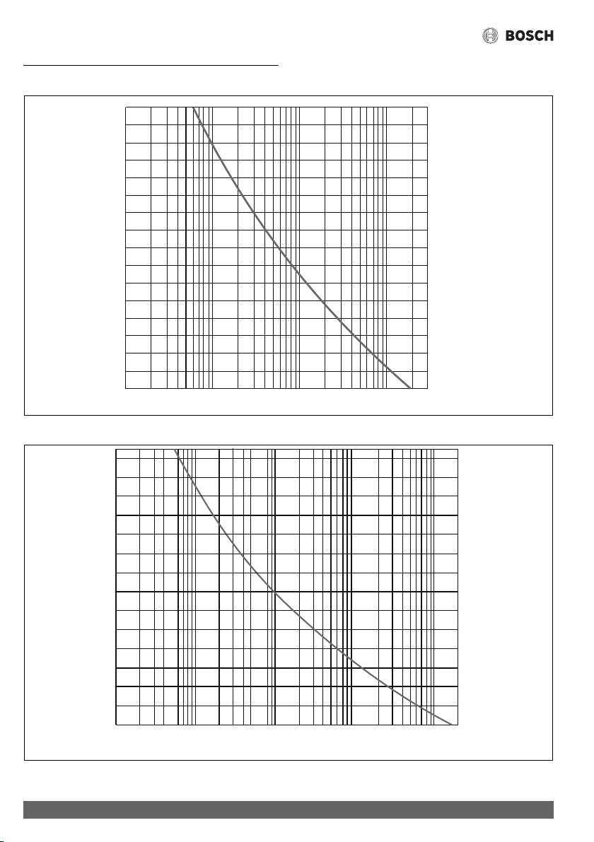
Sensor resistance charts
Greentherm T9900 SE/i – 6 720 813 635 (2022/01)
76
11 Sensor resistance charts
Fig. 68 Inlet, outlet and heat exchanger water temperature sensors characteristics
Fig. 69 Flue gases and condensing unit flue gases temperature sensors characteristics
-40
-22
-4 14 32
50 68 86 104 122 140 1
58 176 194
(-40)
(-30)
(-20) (-10) (0) (10) (20) (30) (40) (
50) (60) (70) (80) (90) (100) (110) (120)
212 230 248
0.1
1
100
RESISTANCE (KOHM)
TEMPERA
TURE ºF (ºC)
6720816948-40.1V
10
-40
-4
32 68 104 140 176 212 284 320 392 428 464
(-40)
(-20)
(0) (20) (40) (60) (80) (100) (140) (160) (200) (220) (240)
248
(120)
356
(180)
0.01
0.1
1
10
100
RESISTANCE (KOHM)
TEMPERATURE ºF (ºC)
6720816948-41.1V
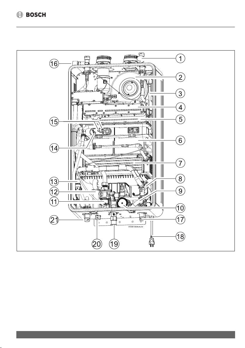
Interior components diagram
77
Greentherm T9900 SE/i – 6 720 813 635 (2022/01)
12 Interior components diagram
12.1 Interior components
Fig. 70 Interior components
[1] Inlet water filter
[2] Air fan
[3] Control unit
[4] Gas manifold
[5] Burner
[6] Heat exchanger
[7] Condensing unit
[8] Main water valve
[9] By-pass pipe
[10] Recirculation pump
[11] Gas valve
[12] Condensate trap
[13] By-pass water valve
[14] Ionization sensor
[15] Ignition electrodes
[16] PRV connection
[17] HE drain
[18] Power cord
[19] Gas connection
[20] Condensate drain
[21] HE drain
Protecting the environment
Greentherm T9900 SE/i – 6 720 813 635 (2022/01)
78
13 Protecting the environment
Packing
The packing box may be fully recycled as confirmed by the
recycling symbol .
Components
Many parts in the heater can be fully recycled in the end of the
product life. Contact your city authorities for information about
the disposal of recyclable products.
Saving water resources:
▶ Make sure you close all the taps after any use. Avoid leaving
the taps dripping. Repair any leaking tap.
▶ Define the temperature you want, in the appliance or with
the remote control. This way you have the precise water
flow needed (mixing cold water to regulate temperature will
increase the water flow with consequent waste of water).
14 Installer Checklist to be completed by
installer upon installation
Installation manual should be left with the owner after the
installation is tested and completed. Additional copies of the
installation manual are available at
www.boschheatingandcooling.com.
Upon completion of the installation complete the checklist
below by answering YES or NO. If any of the answers below are
NO, the installation is not complete. Refer to the Installation
Manual section referenced below in order to complete the
installation. Please contact Technical Support at (866) 330
2730 if additional support is required.
Checklist to be completed by installer
Exhaust and combustion air Yes No Chapter
Vent and fresh air
terminations meet clearance
requirements
4.6.3
Vent and fresh air pipe's
equivalent length in
specification
Combustion air is from a clean
source (free from chemicals,
dust or other pollutants)
Water supply Yes No Chapter
Isolation valves installed on
water heater inlet and outlet
connections
4.10
Water lines flushed and inlet
filter cleaned
Cold water and hot water lines
are installed in correct
position. (Cold on right, hot on
left)
When the cold supply is turned
off no water come out of any
hot taps
Provided PRV installed with
proper pipe away to drain
4.10
Water pressure in range 3.2
Water quality requirements in
range
4.9
Installer Checklist to be completed by installer upon installation
79
Greentherm T9900 SE/i – 6 720 813 635 (2022/01)
Table 27
Condensate Yes No Chapter
Condensate drain line
installed with neutralizer
Condensate drain pitched to a
drain or to a condensate pump
4.6.5
Condensate protected from
freezing
Electrical power Yes No Chapter
120 VAC with ground 3.2
Gas supply Yes No Chapter
Shutoff installed on gas supply
line
3.2; 4.8; 4.1
Gas line sized to as needed
according to NFPA 54 or CSA
B 149
Gas line leak checked
If an LP conversion is the LP kit
installed
4.7.2
Gas pressure in range 3.2
Serial number
Serial number is located on
the rating plate which is
located on the left side (when
facing appliance front) of the
cover.
______________________________
General Yes No
Manual given to customer or
left with the water heater
Installation date:
Installing company name:
Address:
Phone:
Checklist to be completed by installer

List of used Open Source Components
Greentherm T9900 SE/i – 6 720 813 635 (2022/01)
80
15 List of used Open Source Components
The following open source software (OSS) components are
included in this product:
Table 28
15.1 Arphic Public License
Copyright (C) 1999 Arphic Technology Co., Ltd.
11Fl. No.168, Yung Chi Rd., Taipei, 110 Taiwan
All rights reserved except as specified below.
Everyone is permitted to copy and distribute verbatim copies of
this license document, but changing it is forbidden.
Preamble
The licenses for most software are designed to take away your
freedom to share and change it. By contrast, the ARPHIC
PUBLIC LICENSE specifically permits and encourages you to
use this software, provided that you give the recipients all the
rights that we gave you and make sure they can get the
modifications of this software.
Legal Terms
Definitions:
Throughout this License, "Font" means the TrueType fonts "AR
PL Mingti2L Big5", "AR PL KaitiM Big5" (BIG-5 character set)
and "AR PL SungtiL GB", "AR PL KaitiM GB" (GB character set)
which are originally distributed by Arphic, and the derivatives
of those fonts created through any modification including
modifying glyph, reordering glyph, converting format, changing
font name, or adding/deleting some characters in/from glyph
table.
"PL" means "Public License".
"Copyright Holder" means whoever is named in the copyright or
copyrights for the Font.
"You" means the licensee, or person copying, redistributing or
modifying the Font.
"Freely Available" means that you have the freedom to copy or
modify the Font as well as redistribute copies of the Font under
the same conditions you received, not price. If you wish, you
can charge for this service.
Copying & Distribution
You may copy and distribute verbatim copies of this Font in any
medium, without restriction, provided that you retain this
license file (ARPHICPL.TXT) unaltered in all copies.
Modification
You may otherwise modify your copy of this Font in any way,
including modifying glyph, reordering glyph, converting
format, changing font name, or adding/deleting some
characters in/from glyph table, and copy and distribute such
modifications under the terms of Section 1 above, provided
that the following conditions are met:
You must insert a prominent notice in each modified file stating
how and when you changed that file.
You must make such modifications Freely Available as a whole
to all third parties under the terms of this License, such as by
offering access to copy the modifications from a designated
place, or distributing the modifications on a medium
customarily used for software interchange.
If the modified fonts normally reads commands interactively
when run, you must cause it, when started running for such
interactive use in the most ordinary way, to print or display an
announcement including an appropriate copyright notice and a
notice that there is no warranty (or else, saying that you provide
a warranty) and that users may redistribute the Font under
these conditions, and telling the user how to view a copy of this
License.
These requirements apply to the modified work as a whole. If
identifiable sections of that work are not derived from the Font,
and can be reasonably considered independent and separate
works in themselves, then this License and its terms, do not
apply to those sections when you distribute them as separate
works. Therefore, mere aggregation of another work not based
on the Font with the Font on a volume of a storage or
distribution medium does not bring the other work under the
scope of this License.
Condition Subsequent
You may not copy, modify, sublicense, or distribute the Font
except as expressly provided under this License. Any attempt
otherwise to copy, modify, sublicense or distribute the Font will
automatically retroactively void your rights under this License.
However, parties who have received copies or rights from you
under this License will keep their licenses valid so long as such
Name of OSS
Component
Version of OSS
Component
Name and Version of License (License text
can be found in Appendix below)
More Information
Arphic Technology 1.3.0 Arphic Public License See chapter 15.1
Copyright (C) 1999 Arphic
Technology Co., Ltd.
SIL International 1.000 SIL Open Font License 1.1 See chapter 15.2
Copyright (C) 2004-2008, SIL
International

List of used Open Source Components
81
Greentherm T9900 SE/i – 6 720 813 635 (2022/01)
parties remain in full compliance.
Acceptance
You are not required to accept this License, since you have not
signed it. However, nothing else grants you permission to copy,
modify, sublicense or distribute the Font. These actions are
prohibited by law if you do not accept this License. Therefore,
by copying, modifying, sublicensing or distributing the Font,
you indicate your acceptance of this License and all its terms
and conditions.
Automatic Receipt
Each time you redistribute the Font, the recipient automatically
receives a license from the original licensor to copy, distribute
or modify the Font subject to these terms and conditions. You
may not impose any further restrictions on the recipients'
exercise of the rights granted herein. You are not responsible
for enforcing compliance by third parties to this License.
Contradiction
If, as a consequence of a court judgment or allegation of patent
infringement or for any other reason (not limited to patent
issues), conditions are imposed on you (whether by court
order, agreement or otherwise) that contradict the conditions
of this License, they do not excuse you from the conditions of
this License. If you cannot distribute so as to satisfy
simultaneously your obligations under this License and any
other pertinent obligations, then as a consequence you may not
distribute the Font at all. For example, if a patent license would
not permit royalty-free redistribution of the Font by all those
who receive copies directly or indirectly through you, then the
only way you could satisfy both it and this License would be to
refrain entirely from distribution of the Font.
If any portion of this section is held invalid or unenforceable
under any particular circumstance, the balance of the section is
intended to apply and the section as a whole is intended to
apply in other circumstances.
NO WARRANTY
BECAUSE THE FONT IS LICENSED FREE OF CHARGE, THERE IS
NO WARRANTY FOR THE FONT, TO THE EXTENT PERMITTED
BY APPLICABLE LAW. EXCEPT WHEN OTHERWISE STATED IN
WRITING THE COPYRIGHT HOLDERS OR OTHER PARTIES
PROVIDE THE FONT "AS IS" WITHOUT WARRANTY OF ANY
KIND, EITHER EXPRESSED OR IMPLIED, INCLUDING BUT NOT
LIMITED TO THE IMPLIED WARRANTIES OF
MERCHANTABILITY AND FITNESS FOR A PARTICULAR
PURPOSE. THE ENTIRE RISK AS TO THE QUALITY AND
PERFORMANCE OF THE FONT IS WITH YOU. SHOULD THE
FONT PROVE DEFECTIVE, YOU ASSUME THE COST OF ALL
NECESSARY SERVICING, REPAIR OR CORRECTION.
DAMAGES WAIVER
UNLESS REQUIRED BY APPLICABLE LAW OR AGREED TO IN
WRITING, IN NO EVENT WILL ANY COPYRIGHTT HOLDERS, OR
OTHER PARTIES WHO MAY COPY, MODIFY OR REDISTRIBUTE
THE FONT AS PERMITTED ABOVE, BE LIABLE TO YOU FOR ANY
DIRECT, INDIRECT, CONSEQUENTIAL, INCIDENTAL, SPECIAL
OR EXEMPLARY DAMAGES ARISING OUT OF THE USE OR
INABILITY TO USE THE FONT (INCLUDING BUT NOT LIMITED
TO PROCUREMENT OF SUBSTITUTE GOODS OR SERVICES;
LOSS OF USE, DATA OR PROFITS; OR BUSINESS
INTERRUPTION), EVEN IF SUCH HOLDERS OR OTHER PARTIES
HAVE BEEN ADVISED OF THE POSSIBILITY OF SUCH
DAMAGES.
15.2 SIL Open Font License 1.1
SIL OPEN FONT LICENSE
Version 1.1 - 26 February 2007
PREAMBLE
The goals of the Open Font License (OFL) are to stimulate
worldwide development of collaborative font projects, to
support the font creation efforts of academic and linguistic
communities, and to provide a free and open framework in
which fonts may be shared and improved in partnership with
others.
The OFL allows the licensed fonts to be used, studied, modified
and redistributed freely as long as they are not sold by
themselves. The fonts, including any derivative works, can be
bundled, embedded, redistributed and/or sold with any
software provided that any reserved names are not used by
derivative works. The fonts and derivatives, however, cannot
be released under any other type of license. The requirement
for fonts to remain under this license does not apply to any
document created using the fonts or their derivatives.
DEFINITIONS
"Font Software" refers to the set of files released by the
Copyright Holder(s) under this license and clearly marked as
such. This may include source files, build scripts and
documentation.
"Reserved Font Name" refers to any names specified as such
after the copyright statement(s).
"Original Version" refers to the collection of Font Software
components as distributed by the Copyright Holder(s).
"Modified Version" refers to any derivative made by adding to,
deleting, or substituting — in part or in whole — any of the
components of the Original Version, by changing formats or by
porting the Font Software to a new environment.
"Author" refers to any designer, engineer, programmer,
technical writer or other person who contributed to the Font
Software.
PERMISSION & CONDITIONS
Permission is hereby granted, free of charge, to any person
obtaining a copy of the Font Software, to use, study, copy,
merge, embed, modify, redistribute, and sell modified and

FCC Regulatory notices
Greentherm T9900 SE/i – 6 720 813 635 (2022/01)
82
unmodified copies of the Font Software, subject to the
following conditions:
1. Neither the Font Software nor any of its individual
components, in Original or Modified Versions, may be sold
by itself.
2. Original or Modified Versions of the Font Software may be
bundled, redistributed and/or sold with any software,
provided that each copy contains the above copyright
notice and this license. These can be included either as
stand-alone text files, human-readable headers or in the
appropriate machine-readable metadata fields within text
or binary files as long as those fields can be easily viewed by
the user.
3. No Modified Version of the Font Software may use the
Reserved Font Name(s) unless explicit written permission
is granted by the corresponding Copyright Holder. This
restriction only applies to the primary font name as
presented to the users.
4. The name(s) of the Copyright Holder(s) or the Author(s) of
the Font Software shall not be used to promote, endorse or
advertise any Modified Version, except to acknowledge the
contribution(s) of the Copyright Holder(s) and the
Author(s) or with their explicit written permission.
5. The Font Software, modified or unmodified, in part or in
whole, must be distributed entirely under this license, and
must not be distributed under any other license. The
requirement for fonts to remain under this license does not
apply to any document created using the Font Software.
TERMINATION
This license becomes null and void if any of the above
conditions are not met.
DISCLAIMER
THE FONT SOFTWARE IS PROVIDED "AS IS", WITHOUT
WARRANTY OF ANY KIND, EXPRESS OR IMPLIED, INCLUDING
BUT NOT LIMITED TO ANY WARRANTIES OF
MERCHANTABILITY, FITNESS FOR A PARTICULAR PURPOSE
AND NONINFRINGEMENT OF COPYRIGHT, PATENT,
TRADEMARK, OR OTHER RIGHT. IN NO EVENT SHALL THE
COPYRIGHT HOLDER BE LIABLE FOR ANY CLAIM, DAMAGES
OR OTHER LIABILITY, INCLUDING ANY GENERAL, SPECIAL,
INDIRECT, INCIDENTAL, OR CONSEQUENTIAL DAMAGES,
WHETHER IN AN ACTION OF CONTRACT, TORT OR
OTHERWISE, ARISING FROM, OUT OF THE USE OR INABILITY
TO USE THE FONT SOFTWARE OR FROM OTHER DEALINGS IN
THE FONT SOFTWARE.
16 FCC Regulatory notices
Modification statement
Bosch Termotecnologia S.A has not approved any changes or
modifications to this device by the user. Any changes or
modifications could void the user’s authority to operate the
equipment.
Interference statement
This device complies with Part 15 of the FCC Rules and
Industry Canada licence-exempt RSS standard(s). Operation is
subject to the following two conditions: (1) this device may not
cause interference, and (2) this device must accept any
interference, including interference that may cause undesired
operation of the device.
Wireless notice
This device complies with FCC radiation exposure limits set
forth for an uncontrolled environment and meets the FCC radio
frequency (RF) Exposure Guidelines and RSS-102 of the ISED
radio frequency (RF) Exposure rules. This transmitter must not
be co-located or operating in conjunction with any other
antenna or transmitter. This device needs to be installed and
used on distance greater than 20cm from human body.
FCC Class B digital device notice
This equipment has been tested and found to comply with the
limits for a Class B digital device, pursuant to part 15 of the FCC
Rules.
These limits are designed to provide reasonable protection
against harmful interference in a residential installation. This
equipment generates, uses and can radiate radio frequency
energy and, if not installed and used in accordance with the
instructions, may cause harmful interference to radio
communications. However, there is no guarantee that
interference will not occur in a particular installation.
If this equipment does cause harmful interference to radio or
television reception, which can be determined by turning the
equipment off and on, the user is encouraged to try to correct
the interference by one or more of the following measures:
• Reorient or relocate the receiving antenna.
• Increase the separation between the equipment and
receiver.
• Connect the equipment into an outlet on a circuit different
from that to which the receiver is connected.
• Consult the dealer or an experienced radio/TV technician
for help


United States and Canada
Bosch Thermotechnology Corp.
50 Wentworth Avenue
Londonderry, NH 03053
Tel. 603-552-1100
Fax 603-965-7581
www.boschheatingandcooling.com
U.S.A.
Products manufactured by
Bosch Thermotechnik GmbH
Junkersstrasse 20-24
D-73249 Wernau
www.bosch-thermotechnology.com
Bosch Thermotechnology Corp. reserves the right
to make changes without notice due to continuing
engineering and technological advances.