Loading ...
Loading ...
Loading ...
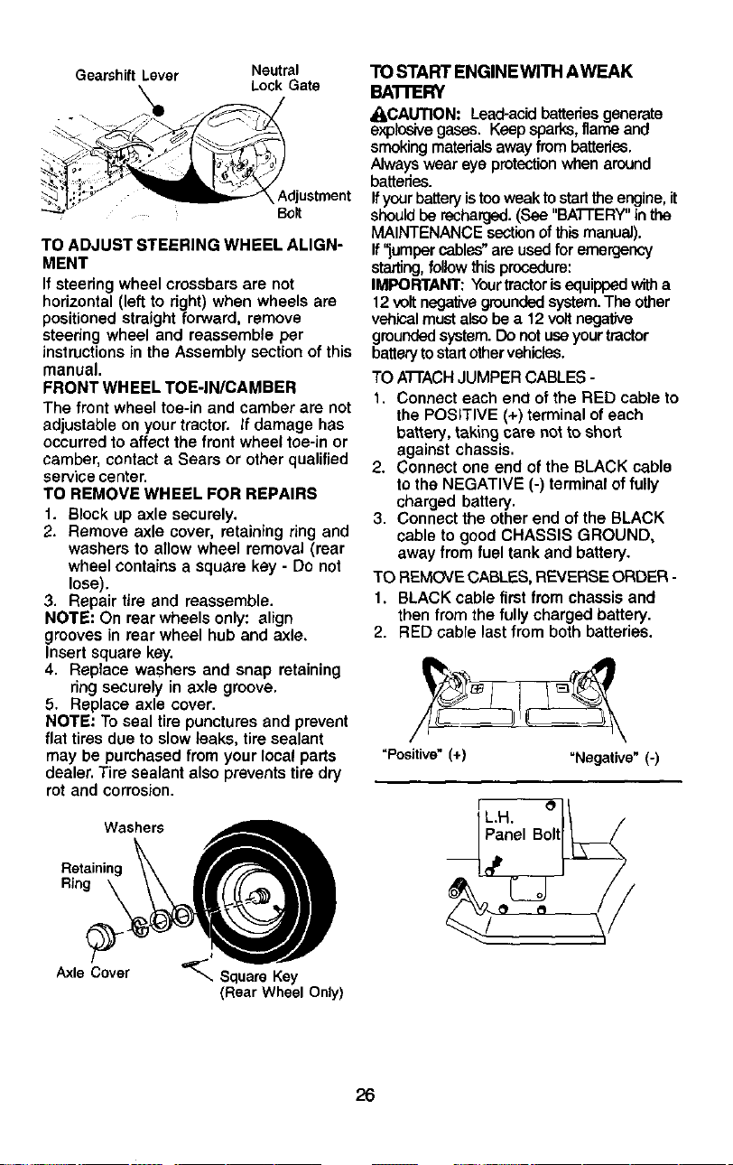
Gearshift Lever Neutral
Lock Gate
. _ _.
i .
:_,_ _;_ "_;--_'X Adjustment
_" Bo_t
TO ADJUST STEERING WHEEL ALIGN-
MENT
If steedng wheel crossbars are not
horizontal (left to right) when wheels are
positioned straight forward, remove
steering wheel and reassemble per
instructions in the Assembly section of this
manual.
FRONT WHEEL TOE-IN/CAMBER
The front wheel toe-le and camber are not
adjustable on your tractor. If damage has
occurred to affect the front wheel toe-in or
camber, contact a Sears or other qualified
service center.
TO REMOVE WHEEL FOR REPAIRS
1. Block up axle securely.
2. Remove axle cover, retaining ring and
washers to allow wheel removal (rear
wheel contains a square key - Do not
lose).
3. Repair tire and reassemble.
NOTE: On rear wheels only: align
grooves in rear wheel hub and axle.
Insert square key.
4. Replace washers and snap retaining
ring securely in axle groove.
5. Replace axle cover.
NOTE: To seal tire punctures and prevent
flat tires due to slow leaks, tire sealant
may be purchased from your local parts
dealer. Tire sealant also prevents tire dry
rot and corrosion.
Washers
Retaining _ _r__
Axle Cover _-, Square Key
(Rear Wheel Only)
"1"(3START ENGINEWITH AWEAK
BAI-FERY
_I_CAUTION: Lead-acid batteries generate
explosivegases. Keepsparks, ltame and
smokingmaterials away frombatteries.
Alwayswear eye protectionwhen around
batteries.
Ifyourbattery istooweak to startthe engine,it
shouldbe recharged.(See "BATI'ERY" inthe
MAINTENANCE sectionofthis manual).
If "jumper cables"are used for emergency
starting,follow this procedure:
IMPORTANT: Yourtractorisequipped witha
12 voltnegativegroundedsystem.The other
vehioalmust also be a 12 voltnegative
groundedsystem.Do notuseyour tractor
batterytostartothervehicles.
TO ATI'ACH JUMPER CABLES -
1. Connect each end of the RED cable to
the POSITIVE (+) terminal of each
battery, taking care not to short
against chassis.
2. Connect one end of the BLACK cable
to the NEGATIVE (-) terminal of fully
charged battery.
3. Connect the other end of the BLACK
cable to good CHASSIS GROUND,
away from fuel tank and battery.
TO REMOVE CABLES, REVERSE ORDER -
1. BLACK cable first from chassis and
then from the fully charged battery.
2. RED cable last from both batteries.
"Positive" (+) "Negative"(-)
26
Loading ...
Loading ...
Loading ...