Loading ...
Loading ...
Loading ...
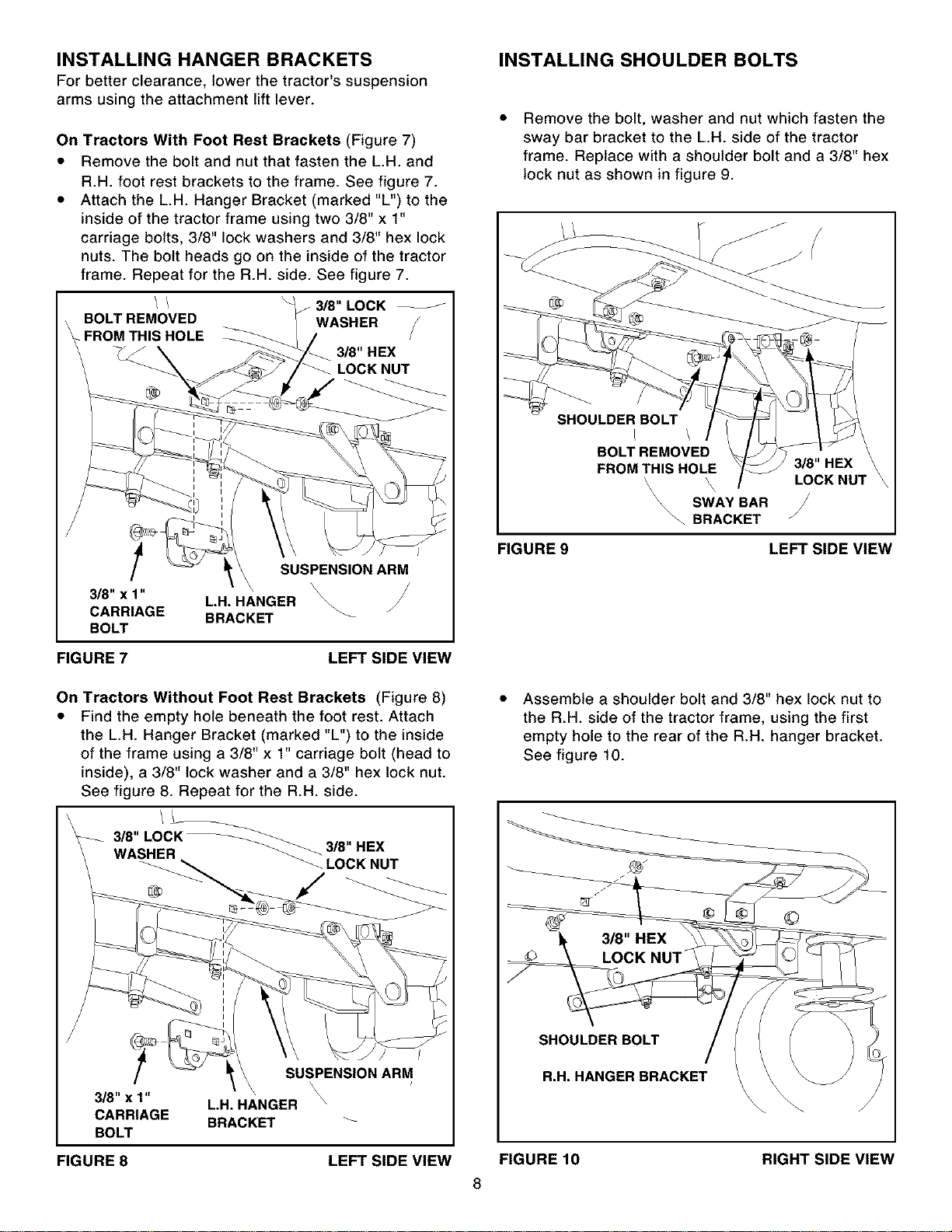
INSTALLING HANGER BRACKETS
For better clearance, lower the tractor's suspension
arms using the attachment lift lever.
On Tractors With Foot Rest Brackets (Figure 7)
• Remove the bolt and nut that fasten the L.H. and
R.H. foot rest brackets to the frame. See figure 7.
• Attach the L.H. Hanger Bracket (marked "L") to the
inside of the tractor frame using two 3/8" x 1"
carriage bolts, 3/8" lock washers and 3/8" hex lock
nuts. The bolt heads go on the inside of the tractor
frame. Repeat for the R.H. side. See figure 7.
/ / _ 3/8" LOCK
BOLT REMOVED WASHER
FROMTHIS HOLE
#J
3/8" HEX
-_ _ LOCK NUT
/
3/8" x 1"
CARRIAGE
BOLT
SUSPENSION ARM
L,H, HANGER _
BRACKET _
FIGURE 7 LEFT SIDE VIEW
INSTALLING SHOULDER BOLTS
Remove the bolt, washer and nut which fasten the
sway bar bracket to the L.H. side of the tractor
frame. Replace with a shoulder bolt and a 3/8" hex
lock nut as shown in figure 9.
SHOULDER BOLT
L \
BOLT REMOVED
FROMTHIS HOLE 3/8" HEX
'\ LOCKNUT
\
SWAY BAR
\\\\'-. BRACKET /
FIGURE 9 LEFT SIDE VIEW
On Tractors Without Foot Rest Brackets (Figure 8)
• Find the empty hole beneath the foot rest. Attach
the L.H. Hanger Bracket (marked "L") to the inside
of the frame using a 3/8" x 1" carriage bolt (head to
inside), a 3/8" lock washer and a 3/8" hex lock nut.
See figure 8. Repeat for the R.H. side.
3/8,,,OCK
WASHER 3/8" HEX
LOCK NUT
SUSPENSION ARM
\
\ \
3/8" x 1" L.H. HANGER \
CARRIAGE BRACKET _-
BOLT
Assemble a shoulder bolt and 3/8" hex lock nut to
the R.H. side of the tractor frame, using the first
empty hole to the rear of the R.H. hanger bracket.
See figure 10.
©
SHOULDER BOLT
R.H. HANGER BRACKET
RIGHT SIDE VIEW
FIGURE 8 LEFT SIDE VIEW FIGURE 10
8
Loading ...
Loading ...
Loading ...