Installation Instructions
Part No. 112167 Rev B
M
odernist Gas Cooktop
DTG30M954F/DTG36M955F

English2
Contents
Before you begin
3
About this manual
3
Important note to the installer
3
Important note to the consumer
3
Important note to the servicer
3
Customer-service information
4
4
If You Need Help...
Important safety instructions
5
Read all instructions before using this appliance
5
Symbols used in this manual
5
State of California Proposition 65 warning (US only)
5
Commonwealth of Massachusetts
5
Safety and warning information
6
6
7
7
8
8
9
10
General safety
Fire safety
Gas safety
Electrical and grounding safety
Location safety
Installation safety
Cooktop safety
Gas cooktop components
11
What’s in the box
11
Installation requirements
13
Pre-installation checklist
13
Location requirements
13
Gas supply requirements
17
Special gas requirements (gas models sold in Massachusetts)
17
Electrical requirements
18
Installation instructions
19
Installing your gas cooktop
19
LP (Propane) conversion instruction
28
Supplied parts
29
Converting the pressure regulator
32
Converting the cooktop burners
33
Adjusting low flame setting on cooktop burners
34

English 3
Before you begin
About this manual
READ THESE INSTRUCTIONS COMPLETELY AND CAREFULLY.
Important note to the installer
• Read all instructions in these installation instructions before installing the cooktop.
• Remove all packing materials from the cooktop compartments before connecting the
electric and gas supply to the cooktop.
• Observe all governing codes and ordinances.
• Be sure to leave these instructions with the consumer.
• Installation of this appliance requires basic mechanical skills.
• Proper installation is the responsibility of the installer.
• Product failure due to improper installation is not covered under the Warranty.
Important note to the consumer
Keep these instructions with your user manual for reference.
• As when using any heat-generating appliance, certain precautions must be followed.
• Be sure your cooktop is installed and grounded properly by a qualified installer.
• Adjacent wall coverings must be able to withstand heat created by the cooktop.
• Cabinet storage above the cooktop burners should be a minimum of 30 in (76.2 cm).
Important note to the servicer
The electrical diagram is attached inside the burner box.
4 English
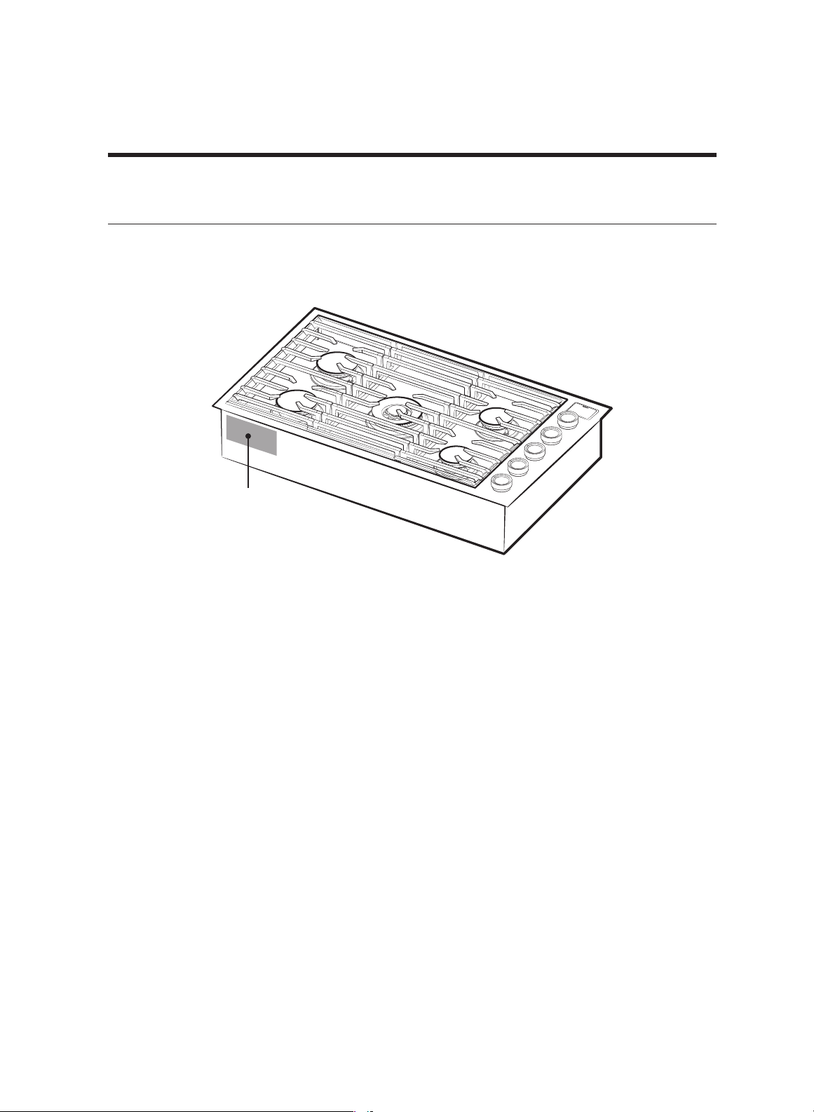
Customer-service information
If You Need Help...
If you have installation issues, contact your Dacor dealer or the Dacor Customer
Assurance Team. Before you call, have available the cooktop's model/serial numbers,
which are on the rating label (front-left side of the cooktop chassis).
Dacor Customer Assurance
Phone: (800) 793-0093 x2813 (USA, Canada)
Hours of Operation: Mon – Fri 5:00 a.m. to 5:00 p.m. Pacific Time
Website: www.dacor.com/customer-care/contact-us
Rating Label
English 5
Important safety instructions
READ ALL INSTRUCTIONS BEFORE USING THIS APPLIANCE
• Electrical and gas equipment with moving parts can be dangerous. The important
safety instructions in this manual are intended to minimize the risk of property
damage, personal injury, and death. Be sure to read them.
• Keep this manual in a handy place so you can refer to it as needed.
Symbols used in this manual
WARNING
Hazards or unsafe practices that may result in severe personal injury or death.
CAUTION
Hazards or unsafe practices that may result in electric shock, personal injury, or property
damage.
NOTE
Useful tips and instructions.
These warning icons and symbols are intended to prevent property damage and personal
injury. Follow them explicitly.
State of California Proposition 65 warning (US only)
WARNING : This product contains chemicals known to the State of California to cause
cancer and birth defects or other reproductive harm.
Gas appliances can cause low-level exposure to Proposition 65 listed substances (including
benzene, carbon monoxide, formaldehyde, and soot) resulting from the incomplete
combustion of LP or natural gas.
Commonwealth of Massachusetts
This product must be installed by a licensed plumber or gas fitter qualified or licensed by
the State of Massachusetts. When using ball-type gas shut-off valves, you must use the
T-handle type. Multiple flexible gas lines must not be connected in series.
6 English
Safety and warning information
General safety
WARNING
To reduce risk of fire, electric shock, personal injury, or death, observe these precautions:
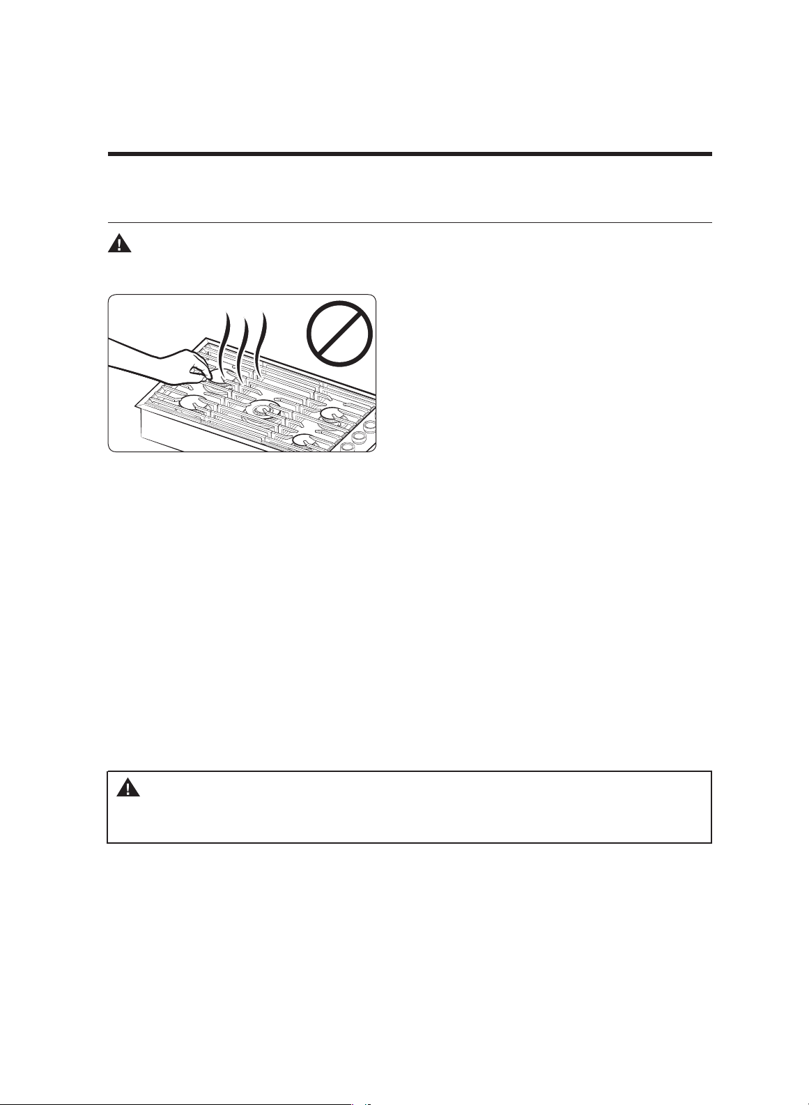
• Do not touch any part of the cooktop
during or immediately after cooking.
• Learn where and how to shut off the
valve that feeds gas to the cooktop.
• Make sure the cooktop's hold-down brackets are properly installed. (See pg. 26.)
• Do not let children
sit/stand on the cooktop or play with any of its parts. Do not leave
children unattended in the kitchen when the cooktop is in use.
• Remove all packaging before operating the cooktop. Keep all packaging away from
children. Properly dispose of packaging as soon as the cooktop is unpacked.
•
Do not keep objects of interest to children on or around the cooktop.
• Do not install the cooktop if it is damaged, malfunctions, or is missing parts.
• Use only dry pot holders.
• Do not use the cooktop to heat sealed food containers.
• Unplug the cooktop before service/maintenance.
• An air curtain or other overhead range hood that blows down on a range shall not be
used with a gas range unless both appliances were designed and tested according to
the Standard for Domestic Gas Ranges, ANSI Z21.1 • CSA1.1, and listed by an
independent testing laboratory for combination use.
WARNING
NEVER use the cooktop as a space heater. Doing so may overheat the oven and
result in carbon monoxide poisoning.
English 7
Fire safety
WARNING
To reduce risk of fire, electric shock, personal injury, or death, observe these precautions:
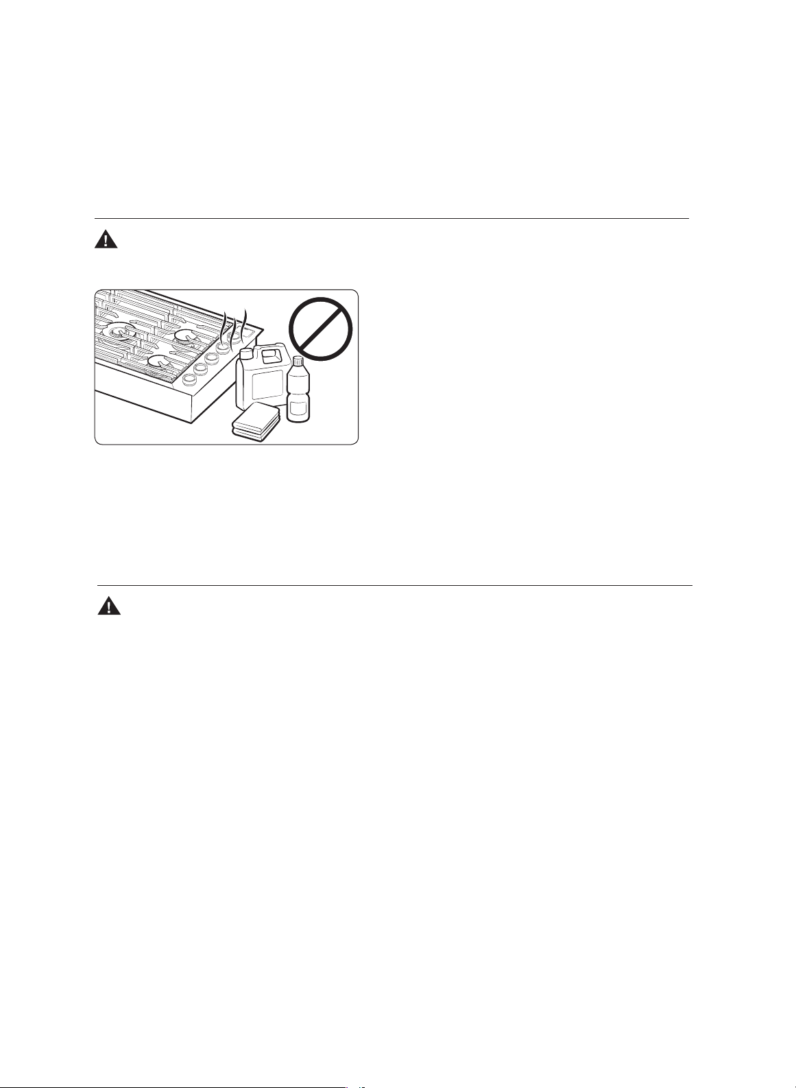
•
Do not store/place/use combustible
material (e.g., paper, plastic, pot holders,
linens, alcohol) near the cooktop.
•
Do not wear loose fitting or hanging
clothing while using the cooktop.
•
Do not let flammable material touch a
heating element. Do not use a towel or
other bulky cloth as a pot holder.
• Regularly clean the vents to remove grease buildup.
• Do not douse a grease fire with water, but turn off the burner, and smother the fire
with a tight-fitting lid, or use a multi-purpose, dry-chemical or foam extinguisher.
• Do not heat sealed food containers; pressure may burst container and cause injury.
Gas safety
WARNING
To reduce risk of fire, electric shock, personal injury, or death, observe these precautions:
If you smell gas:
• Close the valve and do not use the cooktop.
• Do not light a match, candle, or cigarette.
• Do not turn on any gas or electric appliances.
• Do not touch an electrical switch or plug in a power cord.
• Do not use any phone in your building.
• Evacuate the building.
• From a neighbor's phone, immediately call the gas supplier, and follow their
directions. (If you cannot reach your gas supplier, call the fire department.)
Checking for gas leaks
Leak-testing the cooktop must be done per manufacturer directions. Do not use a flame
to check for gas leaks. Use a brush to spread a soap-and-water solution around the test
area. If there is a gas leak, small bubbles will appear in the solution.
Electrical and grounding safety
WARNING
To reduce risk of fire, electric shock, personal injury, or death, observe these precautions:
• Plug into a grounded, 3-prong outlet.
• Do not remove the ground prong.
• Do not use an adapter or extension cord.
• Do not use a damaged power plug, cord,
or loose power outlet.
• Do not modify the plug, cord, or outlet.
• Do not put a fuse in a neutral or ground circuit.
• Use a dedicated 120-volt, 60-Hz, 15-amp, AC, fused electrical circuit. A time-delay fuse
or circuit breaker is recommended. Plug only the cooktop into this circuit.
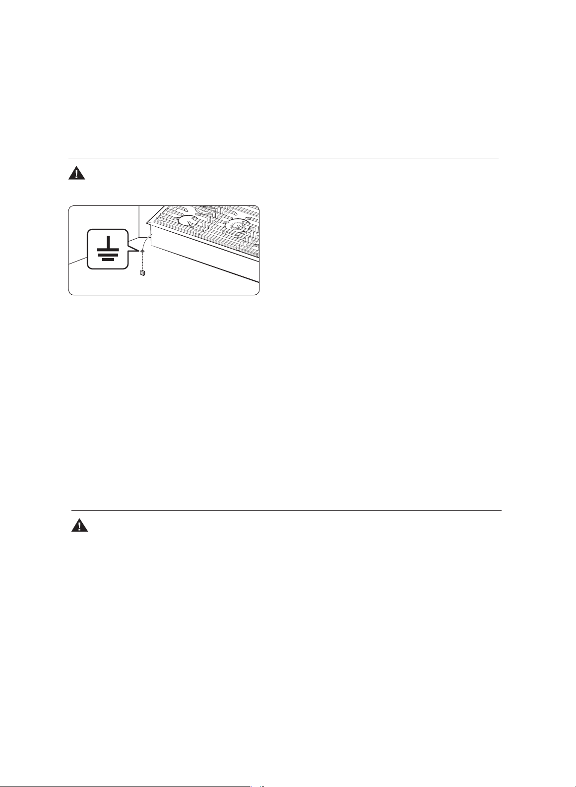
•
Do not connect the ground wire to plastic plumbing lines, gas lines, or hot-water pipes.
• This cooktop must be grounded. In case of malfunction or breakdown, grounding
provides the current a safe path.
•
If unsure your electrical outlet is properly grounded, have a licensed electrician check it.
• If codes allow a separate ground wire, have a qualified electrician determine its path.
• Electrical service to the cooktop must conform to local codes, or in the absence of
local codes, to the National Electrical code/NFPA No. 70 – Latest Revision (for the U.S.)
or the Canadian Electrical Code CSA C22.1 or Latest Revisions.
• The owner shall ensure the cooktop is provided proper electrical service.
Location safety
WARNING
To reduce risk of fire, electric shock, personal injury, or death, observe these precautions:
• The cooktop is for indoor household use only. Do not install the cooktop outside or
anywhere that it will be exposed to weather, water, wind, or strong drafts.
• On windows near the cooktop, do not hang paper blinds or long curtains that could be
blown over the cooktop.
• The cooktop must be installed within easy reach of a grounded, 3-prong outlet.
•
For proper ventilation, the cooktop needs sufficient space below, all around the chassis.
Vents in the chassis exhaust heat and fumes so the cooktop can operate properly.
•
Wall coverings around the cooktop must be able to withstand heat up to 194 °F (90 °C).
• Do not store items above the cooktop. If cabinet storage above the cooktop is needed,
allow at least 30 in. (76.2 cm) between the cooking surface and the cabinet bottom.
8 English

Safety and warning information
Installation safety
WARNING
To reduce risk of fire, electric shock, personal injury, or death, observe these precautions:
• The cooktop should be installed and properly grounded by a
qualified installer, as
specified in this manual. Adjustments and service should be performed only by
qualified installer or service technician.
• Do not service/modify/replace the cooktop or any part of it unless directed in this
manual. All other service should be performed by a qualified techni
cian.
• Use only new, flexible connectors when installing the cooktop.
• Ensure the cooktop's hold-down brackets are properly installed.
(See
pg.
26
.
)
• Remove all tape and packaging materials.
• After unpacking the cooktop,
remove all accessories from inside and around it.
(Cautiously handle the heavy grates.)
• Verify that nothing came loose during shipping.
• Ensure the cooktop is correctly installed/adjusted by a qualified service technician or
installer for the type of gas (natural or LP) you will use. For the cooktop to use
LP gas, a qualified installer/technician must replace every burner orifice with the
provided LP orifice set, and reverse the GPR adapter. The qualified agency performing
this work shall be responsible for the conversion.
• Installation must conform to local codes or in their absence, to the National Fuel Gas
Code, ANSI Z223.1/NFPA.54, latest edition. In Canada, installation must conform with
the current Natural Gas and Propane Installation Code, CAN/CGA-B149.1, or the
current Propane Installation Code, CAN/CGA-B149.2, and with local codes where
applicable. This cooktop has been design-certified by ETL according to ANSI Z21.1,
latest edition, and Canadian Gas Association according to CAN/CGA-1.1, latest edition.
English 9

10 English
Safety and warning information
Cooktop safety
WARNING
To reduce risk of fire, electric shock, personal injury, or death, observe these precautions:
• Turn off all burners that are not in use.
• Do not line the grates or any part of the cooktop with aluminum foil.
• Do not leave burners unattended on medium or high heat settings.
• Before igniting, ensure the burner components are properly seated.
• Use the LITE (flame icon) position to ignite a burner, then ensure the burner ignites. If
ignition fails, turn the knob OFF, and wait a few minutes for the gas to dissipate.
•
When setting a burner to simmer, turn the knob slowly, and ensure the flame stays on.
• Place only cookware on the cooktop.
• Turn off a burner before removing the cookware.
• Ensure all cooktop burners are off and all surfaces are cool to the touch before
removing the grates and disassembling the burners.
• After cleaning the burner head, dry it completely before reassembly.
• Do not pour liquids into the cooktop during cleaning.
• Select cookware that is designed for cooktops and that is large enough to cover the
grates. Burner flames should not extend beyond the bottom of the cookware.
• Do not use cookware that is considerably larger than the grate.
• Turn cookware handles away from active burners or the front edge of the cooktop.
• Stand at a safe distance while frying.
• Heat frying oil slowly, and monitor the oil as it heats. For high-heat frying, monitor
the oil throughout the cooking process.
• If combining fats or oils, do so before heating.
• If possible, use a deep-fry thermometer so you can adjust the heat to keep the oil
below its smoke point. (Know the smoke point of your oil.)
• Use minimal oil when frying.
• Thaw food before frying; do not fry overly cold food or that is clumped with ice.
• Let hot oil/fat cool to room temperature before moving the cookware.
• In case of scalding:
– Immerse the scalded area in cool water for at least 10 minutes.
– Do not apply creams/oils/lotions.
– Cover the scalded area with a clean, dry cloth.
Gas cooktop components
What’s in the box
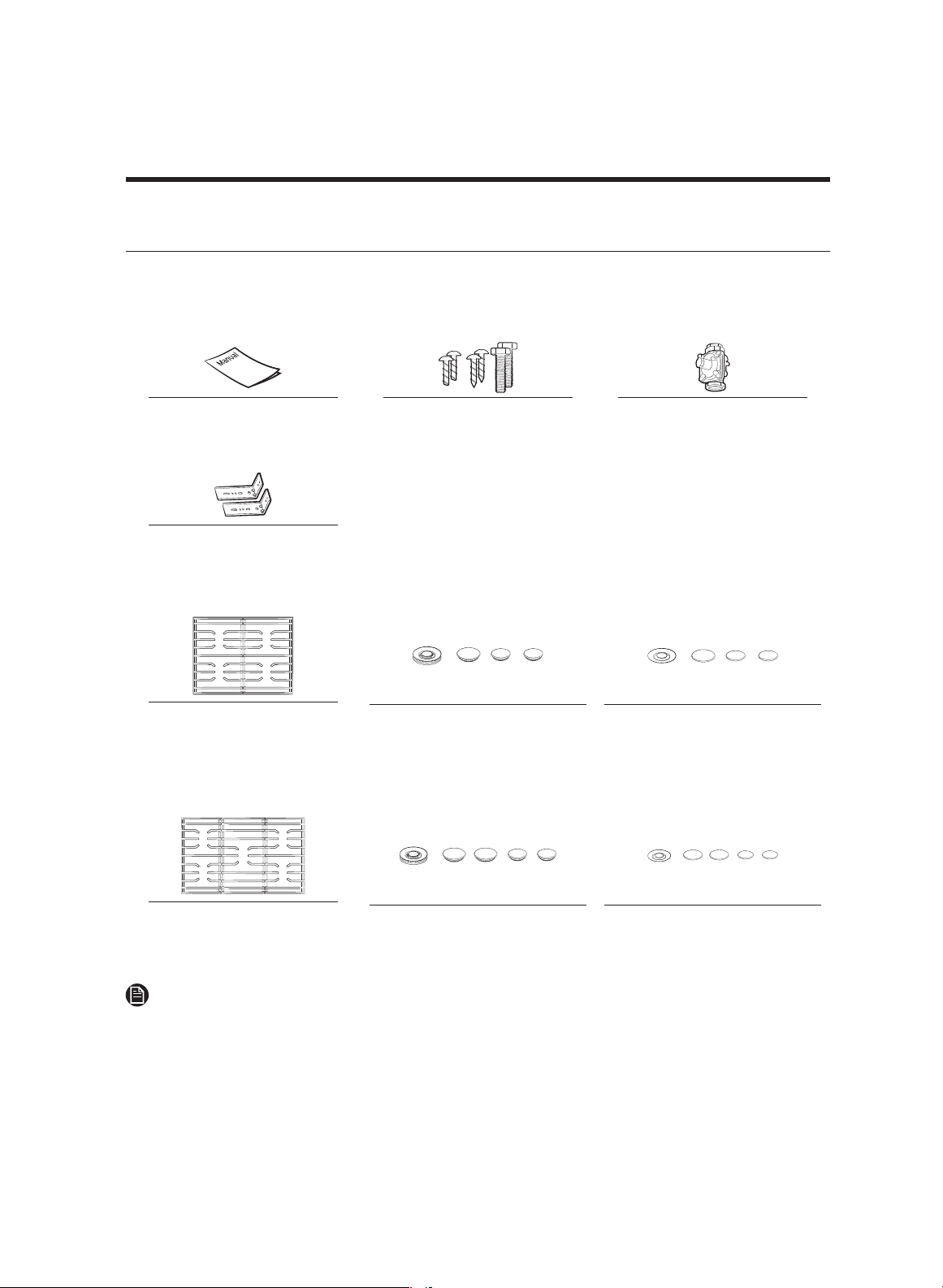
Parts supplied
Common
Manual
Screw (6)
(M4 L10 2 ea, M4 L16 2 ea, 24 3/16 UNC
L145 nut toggle 2 ea)
Regulator (1) *
Hold down brackets (2) *
30” : DTG30M954F*
Cooktop burner grates (2) Surface burners, brass
caps (4)
Porcelain caps (4)
36” : DTG36M955F*
Cooktop burner grates (3)
Surface burners, brass
caps (5)
Porcelain caps (5)
NOTE
• Before installation, verify all of the parts above are present.
• If your cooktop was damaged during shipping or some specified parts are missing,
contact your local retailer. Do not install a damaged or incomplete cooktop.
• If you need an accessory marked with an asterisk, contact the DACOR Call Center at
the phone number on page 3, or visit our online parts website: www.dacor.com.
English 11
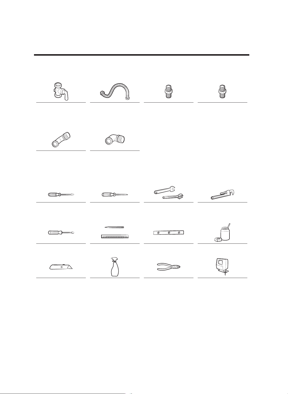
Parts needed
Gas line shut-off
valve
Flexible metal
appliance connector
½ in (ID) x 5 ft
Flare union adapter ¾
in or ½ in (NPT) x ½
in (ID)
Flare union adapter ½
in (NPT) x ½ in (ID)
135-degree elbow
(optional)
90-degree elbow
(optional)
Tools needed
Flat-blade
screwdriver
Phillips screwdriver Open-end or
adjustable wrench
Pipe wrench (2)
¼" Nut driver Pencil and ruler Level Pipe joint compound
Utility knife Soapy water solution Pliers Saber saw
12 English
Installation requirements
Pre-installation checklist
1. Before preparing the countertop opening, verify there will be no conflict between the
cooktop chassis and anything in the cabinet below.
2. Remove packing material, grate boxes, regulator with literature, and literature
package, verify that all items are present before beginning the installation.
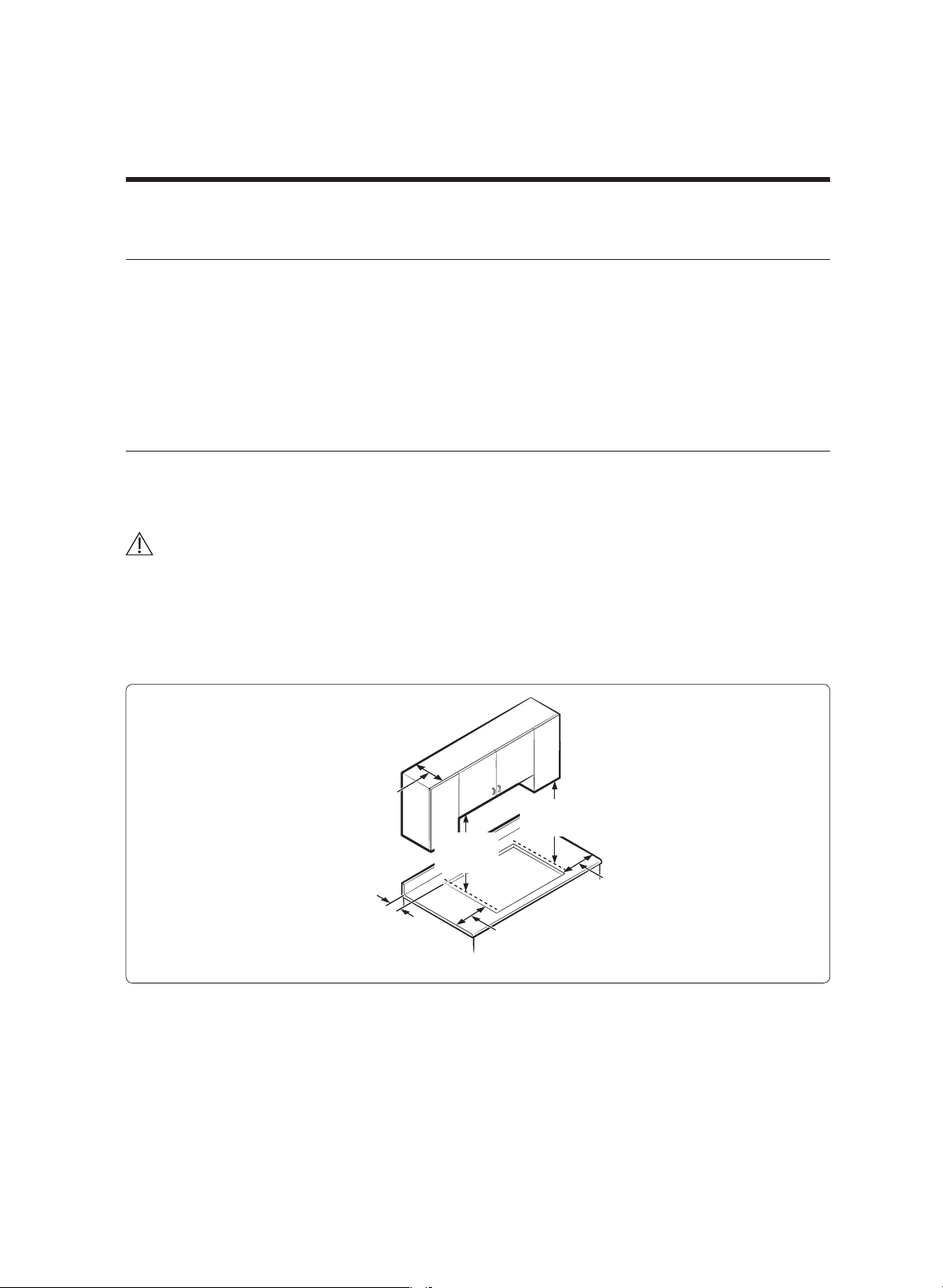
Location requirements
Before installing the cooktop, see the information and graphic below. These dimensions
must be met for safe cooktop operation. Location of the electrical outlet and gas piping
may be adjusted to meet the specified parameters.
CAUTION
The cooktop complies with the maximum allowable wood-cabinet temperature of 194 °F
(90 °C). The wall covering, countertops, and surrounding cabinets must also withstand
this temperature.
Maintain these minimum clearance dimensions:
30” MIN.
(762 mm)
12” MIN.
(304.8 mm)
12” MIN.
(304.8 mm)
18” MIN.
(457 mm)
2
7
/8” MIN.
(72.0 mm)
13” MAX.
(330 mm)
English 13
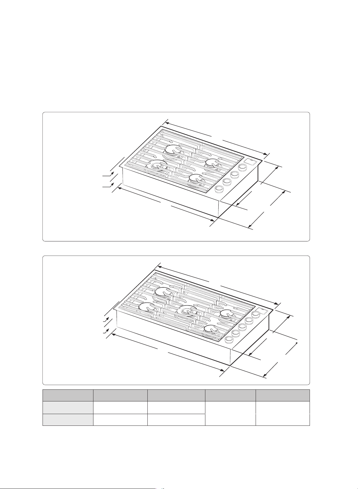
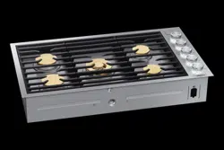
Overall cooktop dimensions
DTG30M954F*
⅓" (8 mm)
countertop to grate
surface
6" (152.4 mm)
chassis Height
A
B
D
C
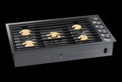
DTG36M955F*
⅓" (.8 cm)
countertop to grate
surface
6" (15.2 cm)
chassis height
A
B
D
C
Model A B C D
DTG30M954
30” (76
.2 cm) 28½” (72.3 cm)
21” (53.3 cm) 19½” (49.5 cm)
DTG36M955
36” (91.4 cm) 34½” (87.5 cm)
14 English
Installation requirements
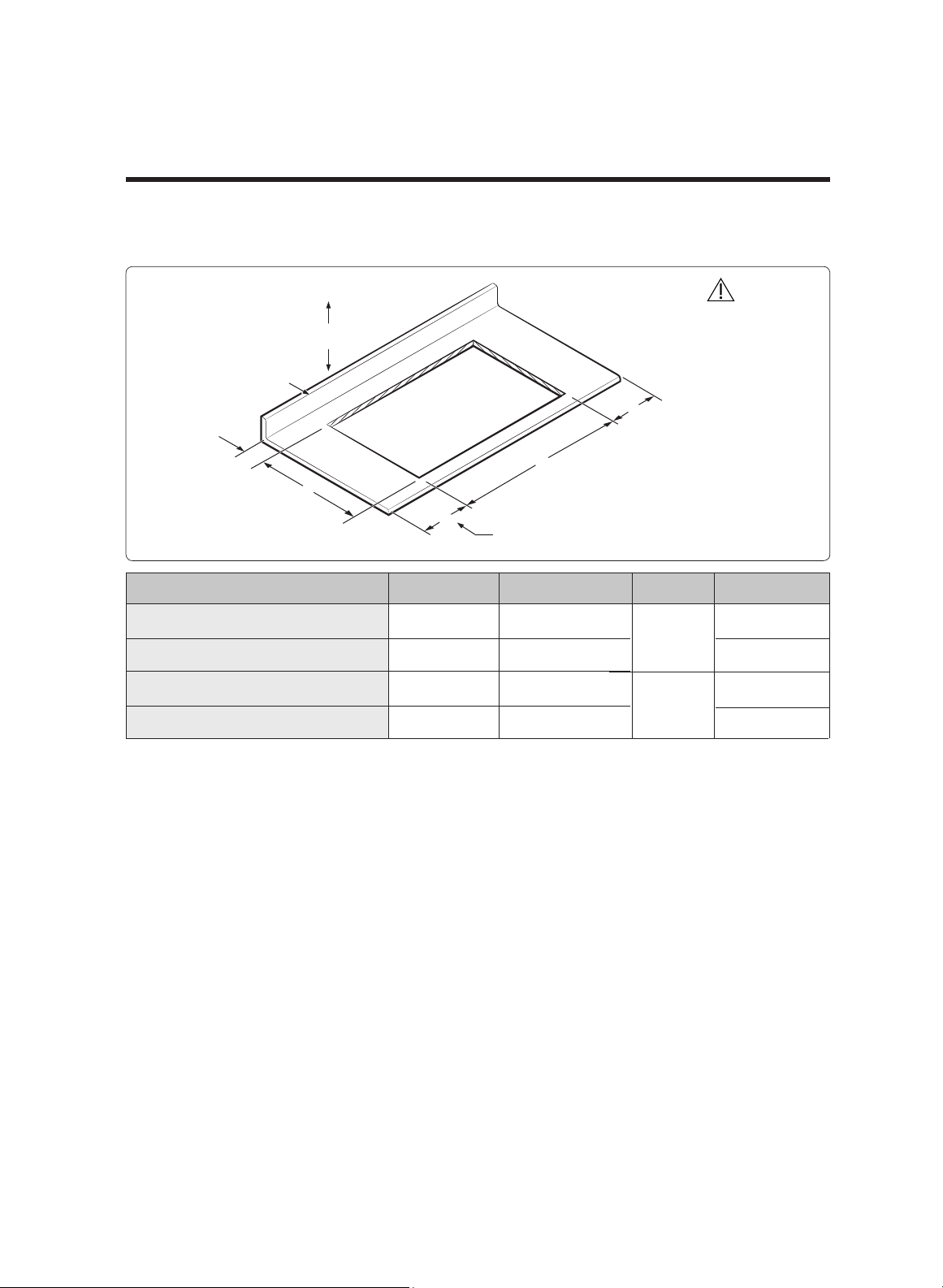
Cutout dimensions of countertop
Vertical
combustible
surface
E
G
H
H
F
Rear wall
Minimum distance to combustible side
wall above countertop (both sides)
Model (E) Min. (F) Min. (G) Min. (H) Min.
DTG30M954 (no downdraft)
2⅞” (7.2 cm)
19¾” (50.1 cm)
28
11
/16”
(72.7 cm)
DTG30M954 with MRV3015M/S
⅜” (0.9 cm)
22½” (57.1 cm)
7½” (19.0 cm)
DTG36M955 (no downdraft)
2⅞” (7.2 cm) 19¾” (50.1 cm)
34
11
/16”
(87.9 cm)
12” (30.4 cm)
DTG36M955 with MRV3615M/S
⅜” (0.9 cm)
22½” (57.1 cm)
7½” (19.0 cm)
CAUTION
Cutout dimensions should
be strictly observed.
English 15
12” (30.4 cm)
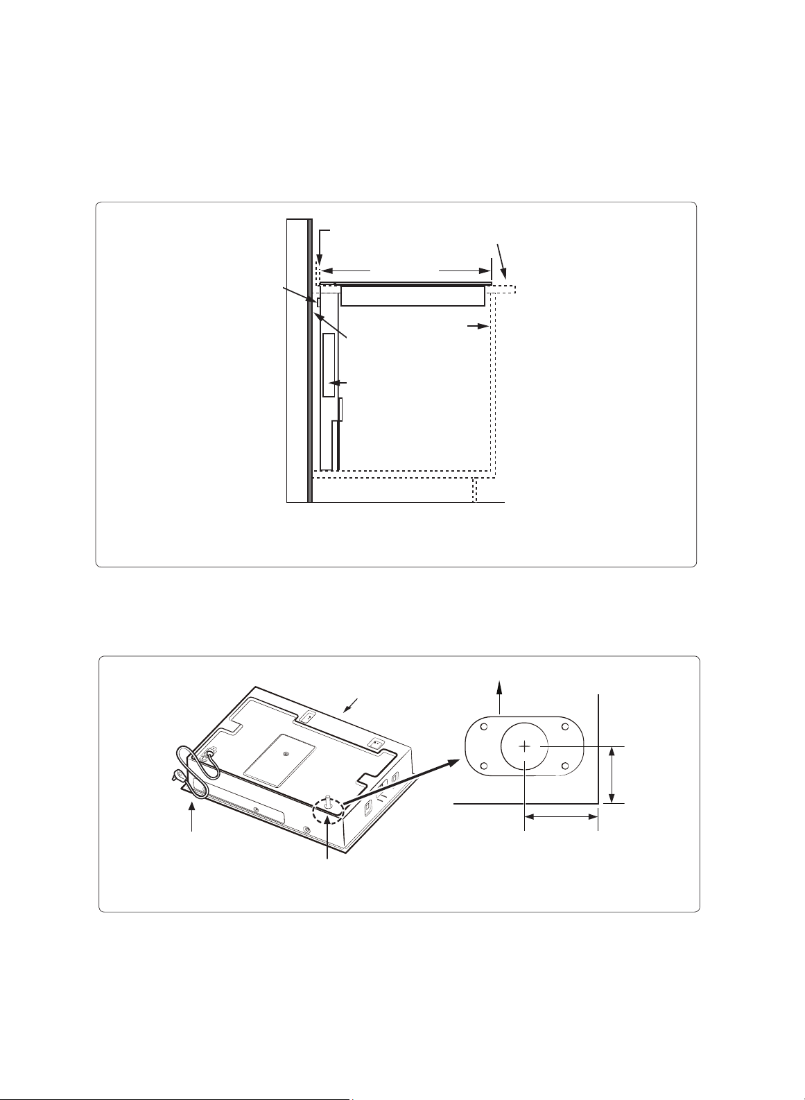
Countertop
23 ⅜" (59.4 cm)
MRV Series Downdraft:
check downdraft
specifications to
determine correct fit
⅜" min. (1.0 cm) space
behind downdraft to
clear stiffener
⅜" min. (1.0 cm)
required for downdraft
cap clearance
Cabiner face
Stiffener
Cooktop with Downdraft: MRV Series
Utility locations and dimensions
Front of unit
Power cord 39
3
/8”
(100.0 cm) long
3
/8”-18 NPT
male gas inlet
* Gas inlet protrudes 1
4
/7 (4.0 cm) from
bottom.
Front of cooktop
Chassis
1¾"
(4.5 cm)
3¾"
(9.6 cm)
16 English
Installation requirements
Gas supply requirements
Provide adequate gas supply
Be sure to supply your cooktop with the gas for which it is designed. Do not try to convert
the cooktop to receive a different type of gas without consulting the gas supplier.
This cooktop converts to natural or propane gas. For LP gas, conversion must be made by a
qualified installer before operating the cooktop. For proper natural-gas operation, the
pressure supplied to the regulator must be 5 – 13 in. (13 – 33 cm) of water column. For LP
gas, the pressure must be 10 – 13 in. (25 – 33 cm) of water column.
When checking proper regulator operation, the inlet pressure must be at least 1 in. (2.5
cm) greater than the operating (manifold) pressure as given. The pressure regulator (at
the inlet of the cooktop manifold) must remain in the supply line whether or not natural
or LP gas is used.
NOTE
• The cooktop has its own regulator. Use only the provided regulator, which must be
installed in the gas line that runs from the cooktop gas inlet to the gas shut-off valve.
• An external manual shut-off valve must be installed between the gas inlet and the
cooktop for turning on/off gas to the appliance.
• Be sure the connectors are installed when you need coupling by a qualified installer.
• On a new cooktop, never install used connectors, which can leak gas and cause
personal injury.
Special gas requirements (gas models sold in Massachusetts)
COMMONWEALTH OF MASSACHUSETTS REQUIREMENTS:
WARNING
• Gas may leak in your system, creating a dangerous situation.
- Gas leaks may not be detected by smell alone.
- Gas suppliers recommend installing a UL-approved gas detector.
• The cooktop must be installed by a plumber or gas fitter certified by the State of
Massachusetts.
•
A T-handle manual gas valve MUST be installed in the gas supply line to your cooktop.
• If a flexible gas connector is used to install your cooktop, multiple flexible gas lines
must not be connected in series.
English 17

Electrical requirements
WARNING
• The owner shall ensure the electrical service meets electrical requirements and that
the electrical outlet is properly installed by a licensed electrician.
• To reduce risk of fire, electric shock, or personal injury:
- Do not use an extension cord or adapter plug with this cooktop.
- The power cord has an equipment-grounding conductor and a grounding plug.
- Ensure a properly grounded outlet is installed by a qualified electrician.
- All wiring and grounding must comply with local codes, or, in their absence, with
the National Electrical Code, ANSI/NFPA No. 70 – Latest Revision (US), or the
Canadian Electrical Code CSA C22.1 – Latest Revisions and local codes.
- The wiring diagram is inside the burner box.
- The cooktop ignition system only operates if the outlet is properly polarized.
- The cooktop requires a 120 V, 60-Hz, AC, approved electrical service with 20-amp
circuit breaker or time-delay fuse.
NOTE
Re-ignition may malfunction if the voltage between Neutral and Ground is over 20 VAC.
Make sure the voltage is under 20 VAC.
• The plug must be firmly inserted in a properly installed, three-prong outlet per local
codes. After a malfunction or breakdown, grounding decreases the risk of electrical
shock by providing the current a safe path.
• Do not use a damaged power plug or loose wall outlet.
• Do not remove the plug's grounding (third) prong. If the plug and outlet do not match
or you have any doubt, have a qualified electrician check the outletand circuit to
ensure the receptacle is properly grounded, and install the proper outlet if needed.
• NEVER connect ground wire to plastic plumbing lines, gas lines, or water pipes.
Additional installation requirements for mobile homes
Installation of appliances designed for mobile-home use must comply with the
Manufactured Home Construction and Safety Standard, Title 24 CFR, Part 3280 (formerly
the Federal Standard for Mobile Home Construction and Safety, Title 24, HUD, Part 280)
or, when such standard does not apply, the Standard for Manufactured Home
Installations, latest edition (Manufactured Home Sites, Communities and Set-Ups), ANSI
A225.1, latest edition, or with local codes. In Canada, mobile home installation must
comply with the current CAN/CSA Z240/MH Mobile Home Installation Code.
18 English
Installation instructions
Installing your gas cooktop
IMPORTANT:
Carefully read these instructions and the Important Safety Instructions section at the
front of this manual BEFORE installing/operating the cooktop. Improper installation,
adjustment, service, or maintenance can lead to personal injury and property damage.
NOTE
To ensure proper installation, you should hire a qualified professional.
Unpacking the cooktop
1. Remove all packaging material.
2. Inventory all included parts against supplied components on pg. 16.
3. Check for and report any damage and missing parts to your retailer.
Installing the cooktop
1. If a downdraft vent will accompany the cooktop, first install the downdraft.
2. Lower the cooktop into the cutout and center it.
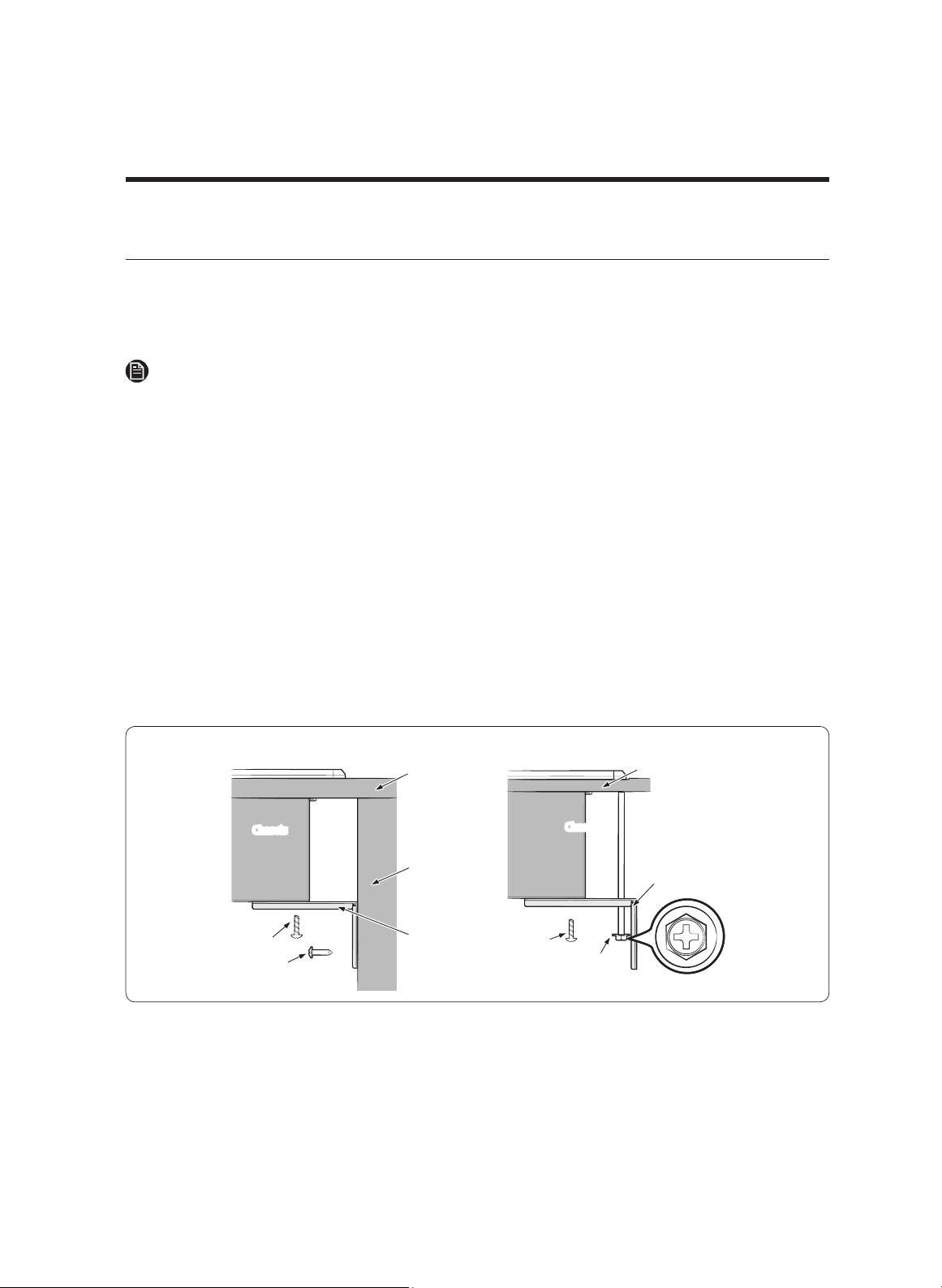
3. Secure the cooktop to the countertop with the hold-down brackets as shown below.
Attaching the hold-down brackets
M4 L10 screw
M4 L16 screw
Case 1.
Countertop
Side wall of
undercounter
cabinet
Hold down
bracket
Chassis
24
3
/16 UNC L145
nut toggle
Case 2.
Countertop
Chassis
Hold down
bracket
M4 L10 screw
English 19
Connecting the gas supply
1. Shut off the main gas-supply valve before disconnecting the old cooktop.
2. Complete the gas hookup.
3. Open the gas valve, and relight the burners on any other gas appliances.
NOTE
Because hard piping restricts movement of the cooktop, use a CSA International-certified
flexible metal appliance connector unless local codes require hard piping.
WARNING
Follow the information in this manual exactly to avoid a fire or explosion, which may
cause property damage and personal injury or death.
• Do not store/use flammable liquids near the cooktop.
• IF YOU SMELL GAS:
- DO NOT light a match, candle, or cigarette.
- DO NOT try to light any appliance.
- DO NOT touch any electrical switch.
- DO NOT use any phone in your building.
- Evacuate the building.
- Immediately, from a neighbor’s phone, call the gas supplier, and follow their
directions. (If you cannot reach the supplier, call the fire department.)
• Installation and service must be performed by a qualified installer, service agency,
or gas supplier.
• Install the provided gas regulator. Do not use the cooktop without it.
• Ensure the regulator arrow points toward the cooktop.
• Do not overtighten gas connections and fittings.
• Before use, test the gas lines for leaks as instructed. Do not test with a flame.
20 English
Installation instructions
Never install an old connector on a new cooktop. For hard piping, carefully align the
pipe; the cooktop cannot be moved once the connection is made.
To prevent gas leaks, apply pipe-joint compound or wrap pipe-thread tape with Teflon
on all male (external) pipe threads.
1. Attach the provided gas-pressure regulator to the cooktop pipe nipple inlet. (For
tight installations, the regulator may be installed upstream from the nipple,
anywhere between the shut-off valve and the cooktop. However, to minimize gas-
pressure loss, attach the regulator as close as possible to the cooktop gas inlet.
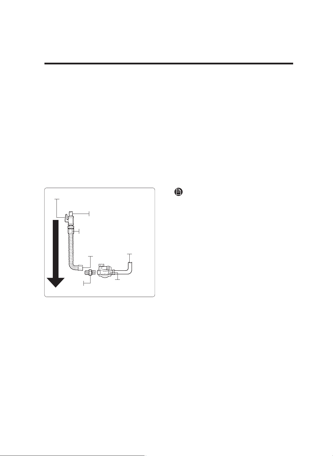
2. Complete the connection by installing a flexible gas line between the pressure
regulator and the shut-off valve.
Flexible connector hookup
Installer: Inform the consumer of the location of the gas shut-off valve.
Gas Shut-Off Valve
Flex
Connector
(6-ft max.)
0.5-in or 0.75-in
Gas Pipe
Adapter
Adapter
Gas Flow into Cooktop
Pressure
Regulator
Tubing Line
to Cooktop
Control
Manifold
NOTE
The gas shut-off valve should be
installed on the gas piping, away from
the appliance, and easily accessible for
quick opening/closing.
English 21
Checking for gas leaks
WARNING
To prevent an explosion/fire hazard possibly leading to personal injury or death, DO
NOT use a flame to check for gas leaks.
When using pressures above 1/2 psig to test the home gas-supply system, disconnect
the cooktop and individual shut-off valve from the gas-supply piping. When using
pressures of 1/2 psig or less to test the gas-supply system, isolate the cooktop from the
system by closing the individual shut-off valve.
1. When all connections are made, ensure all cooktop controls are off, and turn on the
main gas-supply valve.
2. Use a liquid leak detector at all joints and connections to check for gas leaks.
3. Tighten connections as needed to stop gas leakage in the cooktop or supply line.
Making the electrical connections
WARNING
• Disconnect electrical power at the main circuit breaker or fuse box before making any
electrical connections.
• BEFORE operating/testing, follow the grounding requirements on pg. 25. Improper
connection of the grounding plug is an electric-shock risk.
• All gas cooktops come with a power cord connected to the bottom of the cooktop
chassis. (For details, see “Electrical requirements,” page 24.)
• The electrical system, including the power cord, is factory-installed/-wired. Altering
any part of this system may cause a short or overload.
1. Plug in the power cord. (Ensure the outlet meets all applicable electrical codes (see
pg. 24).
2. After installing the cooktop, check the gas-supply line to verify it is connected and
undamaged.
22 English
Installation instructions
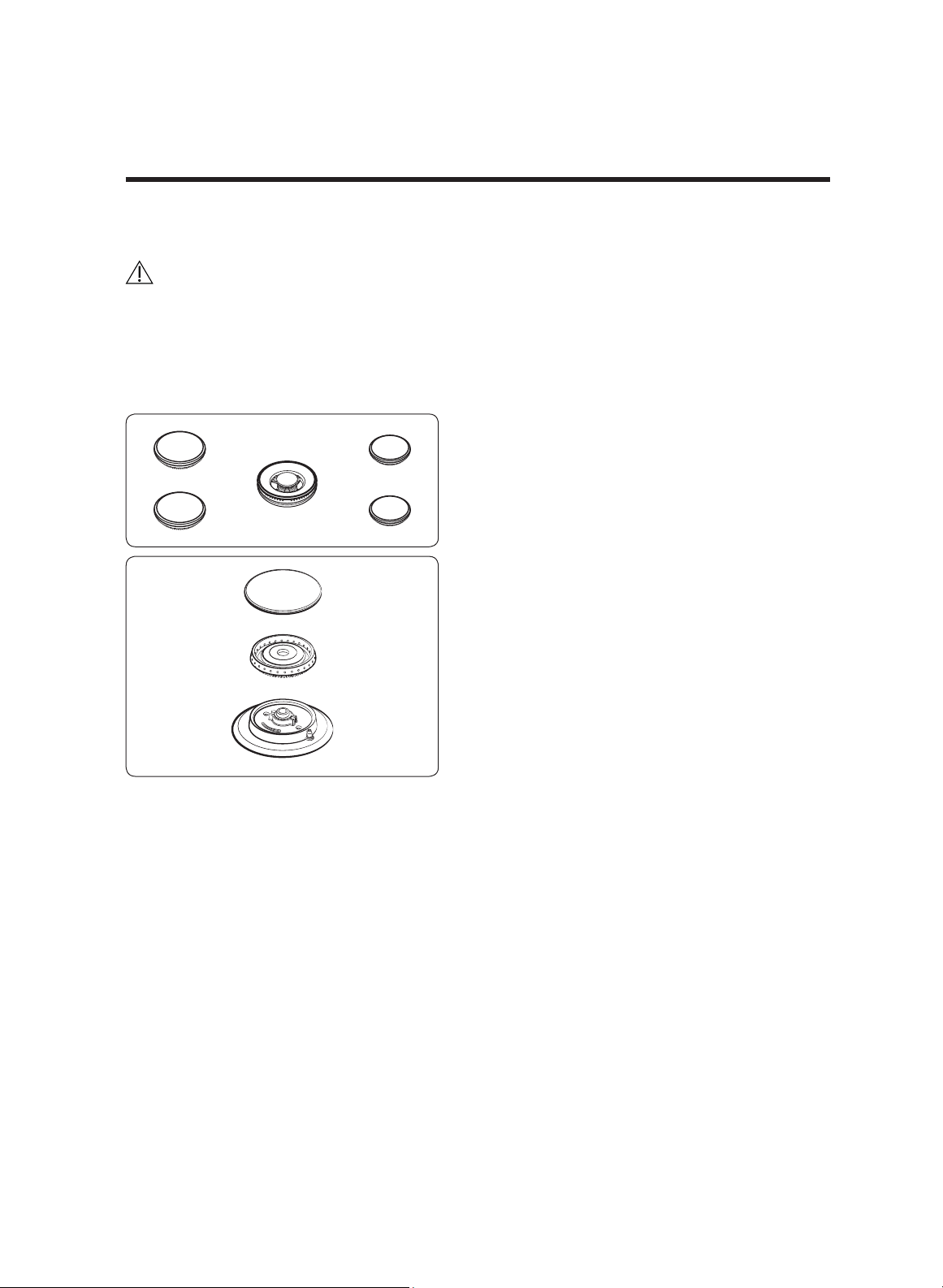
Assembling the cooktop burners
CAUTION
• Ensure all burner parts are in place before operating the cooktop burners.
• Do not push in any cooktop controls while removing the burner; you might receive an
uncomfortable electrical shock.
• Do not touch one burner's electrode while another burner is on.
1. Put the burner heads on their bases
as shown at left. (The electrodes fit in
the slot in the bottom of the heads.)
The heads should be flat and parallel
to the cooktop.
2. Place the corresponding caps on each
burner head.
English 23
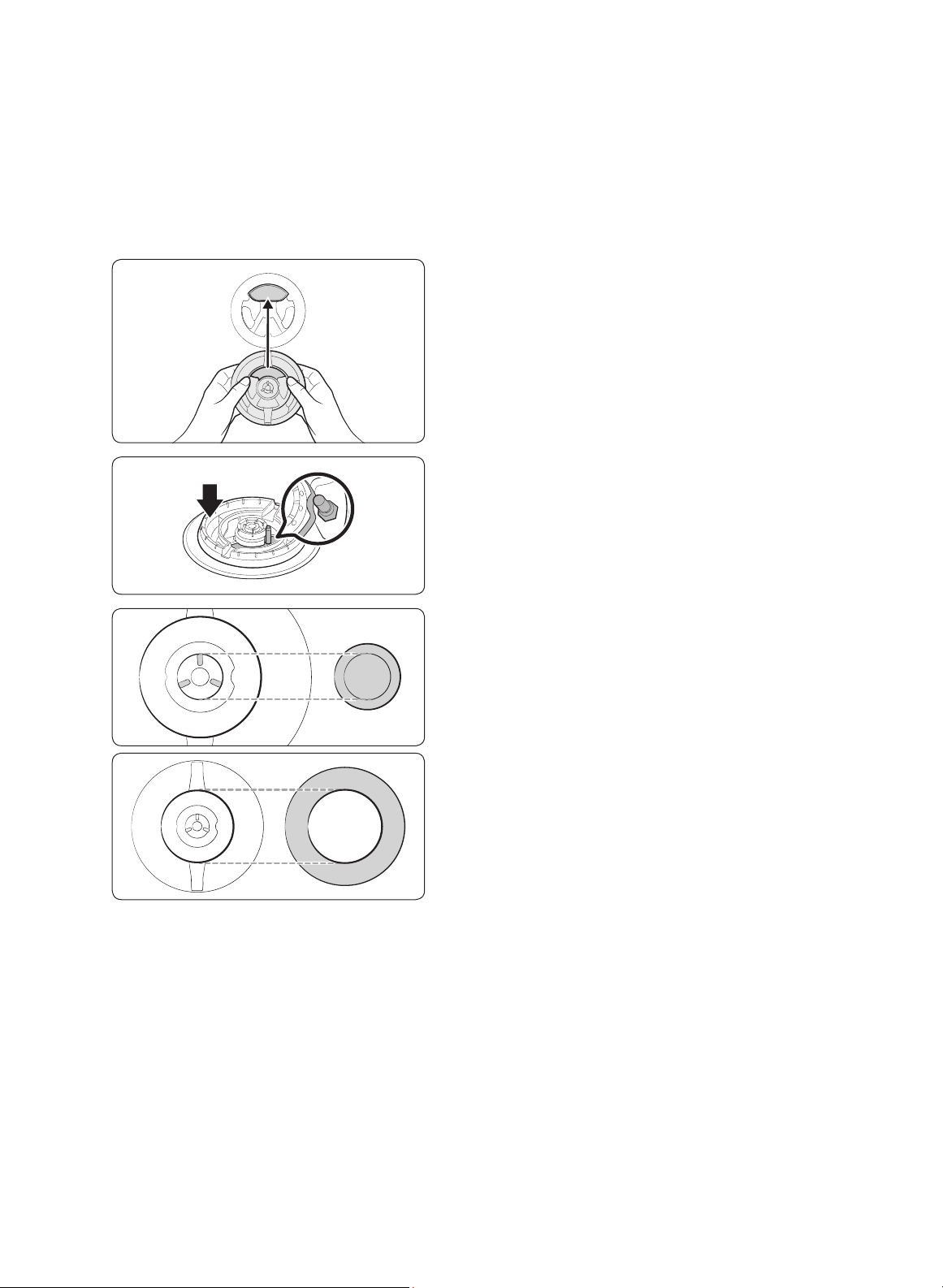
Dual Burner head / caps
1. Orient the burner head so the opening
for the electrode aligns with the
electrode.
2. Install the burner head so the electrode
passes through its opening in the head.
Ensure the burner head lies flat on the
stove top.
3. Match the burner caps to the burners
by size, then install the caps on the
heads.
24 English
Installation instructions
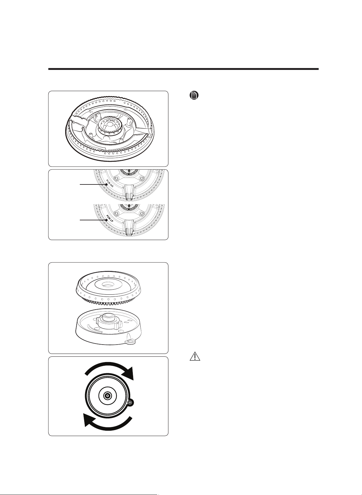
For NG
For LP
NOTE
• The included dual burner head is not
a substitute. One is for LP gas and the
other is for LN gas. Use appropriate gas
type.
- Dual burner head for LP gas is
packed with a plastic bag.
- The letter "For LP" or "For NG" is
engraved on the dual burner head.
• LP burner head also can be found by
the number of holes.
- The burner head with 14 holes in a
quadrant is for LP gas use.
- The burner head with 12 holes in a
quadrant is for LN gas use.
Round Burner head / caps
1.Put the burner heads on their bases as
shown at left. The bottom of the head
fits within the burner base.
2.Turn the head until it drops into place.
Wiggle the head slightly to determine
it is properly seated.
3.
Put the burner caps (brass or porcelain)
atop the burner heads. The ridge
around the bottom edge of the cap fits
around the top of the burner head.
CAUTION
Ensure all burner components (heads and
caps) rest flat and snugly in place.
English 25
Verifying burner function
After the cooktop is fully installed, connected, assembled, and plugged in, verify burner
function. Perform this procedure for each burner in turn.
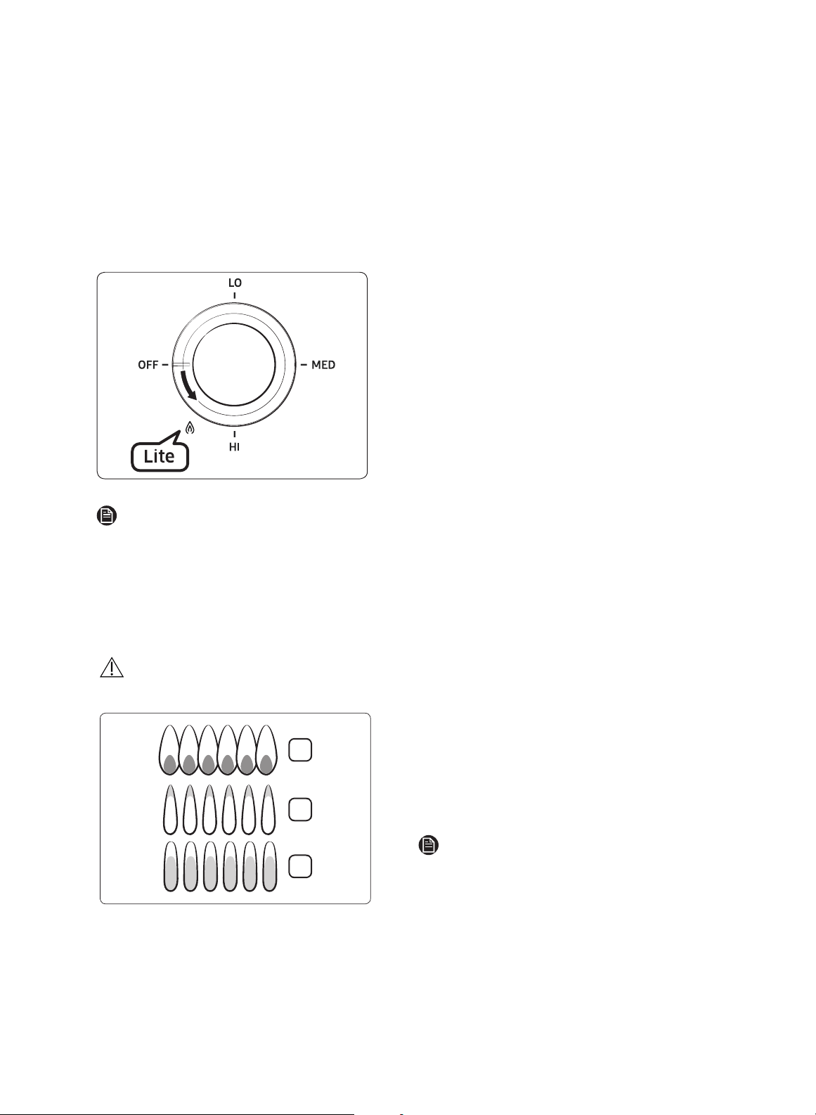
To turn on a cooktop burner
1.Push in, and turn a burner control
knob to the "Lite" position (flame icon).
A "click-click-click...” indicates the
electronic ignition system functions.
The burner ignites in about 4 seconds ,
after air is purged from the gas line.)
2.Turn the knob to the desired setting.
(The “clicking” stops; the flame height
changes from HI to LO as you turn the
knob counterclockwise.)
NOTE
If the burner does not light within 4 seconds, turn
the knob off and wait one minute
before trying again.
Checking flame quality
All burner flames must be visually checked to assess their quality.
CAUTION
If you want measure the flame, take care to avoid burn injuries.
2
3
1
1. Soft blue flames—Normal for natural
gas operation.
2. Yellow tips on outer cones—Normal for
LP gas operation.
3. Yellow flames—Abnormal for any gas
operation; call for service.
NOTE
Normal burner flames look like Ex. 1 or 2.
If the flame looks like Ex. 3, do not use the
cooktop, and call for service.
26 English
English 27
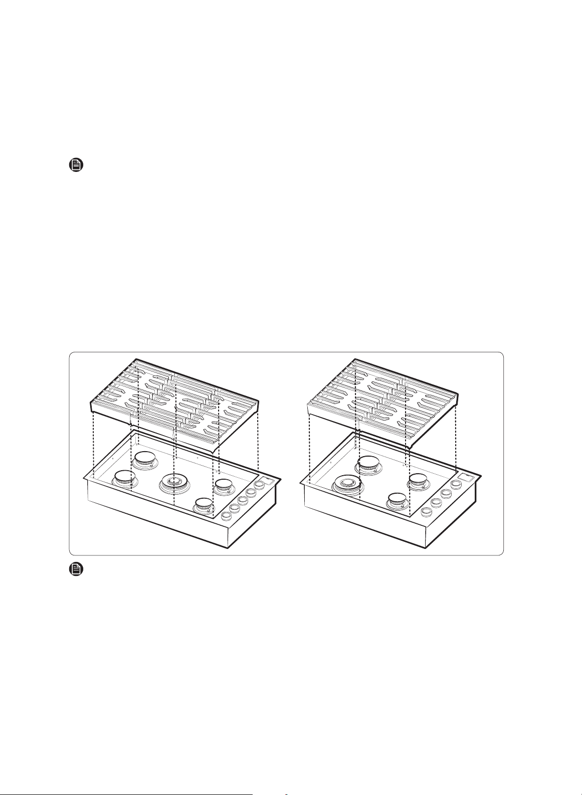
Installing the grates
NOTE
For best results and longest life, install the grates as instructed below. When installed
properly, the openings in the grates are centered over the burners.
The three grates occupy specific positions on the cooktop. For maximum stability and
safe operation, these grates should only be used in their proper positions.
The back of the right grate is notched to help orient the grates correctly. (See the
graphic below.)
To correctly position the grates:
1. Find the notch on the back of the right-hand grate, and orient the grate properly above
the right-hand burners.
2. Gently lower the right-hand grate so its legs rest in the corresponding dimples on the
cooktop.
3. Likewise place the remaining grates so their feet rest in the corresponding dimples.
NOTE
Side grates are interchangeable. Characters (L, for left; R, for right) on the front indicate a
grate's position.
28 English
Installation instructions
Final installation checklist
WARNING
The owner shall be responsible for the cooktop's proper installation.
After installing the cooktop, the installer should review this checklist to confirm the
cooktop is properly installed and ready to operate.
• The gas line is properly connected to the cooktop.
• The gas is turned on.
• All connections were checked for leaks.
• The cooktop is properly plugged in to a grounded electrical outlet.
• The cooktop burners and grates are properly assembled.
• All burners were tested and function properly.
NOTE
Keep the serial-number label (top of the cooktop) in the user manual for easy reference.
LP (Propane) conversion instruction
WARNING
• This conversion must be performed by a qualified installer or gas supplier per
manufacturer directions and all requirements of the governing authority. Failure to
follow ALL instructions could result in serious injury and property damage. The
agency performing this work assumes responsibility for the conversion.
• Know the location of the gas shut-off valve and how to shut it off.
• Unplug or disconnect power before service.
• Do not use the cooktop with LP gas the pressure regulator and burner orifices have
not been converted for LP use. High flames and toxic fumes may cause serious injury.
• Ensure LP gas burner orifices are positioned properly during conversion. Improper
orifice placement will effect burner and cooking performance and could result in
personal injury and product damage.
All Dacor gas cooktops are manufactured to use natural gas. The cooktops ship with LP
Conversion Kits. The kit contains a set of burner orifices corresponding to the cooktop
burners. The orifices are packed in cardboard and placed in a plastic bag. The bag is
packaged with a user manual. The orifice in the pressure regulator is a dual-purpose
orifice (one side for natural gas, the other for LP gas.)
Installation instructions
Supplied parts
The following parts make up the LP conversion kit:
DG69-00306A
LF RF
DG96-00581A (ASSY NOZZLE-KIT)
ORIFICES/ORIFICES/ORIFICIOS
MAIN(PUR)
SUB(GRAY)
MAIN(LIGHT GRN)
SUB(PINK)
LR RR
MAIN(LIGHT BLUE)
SUB(BROWN)
MAIN(LIGHT GRN)
SUB(PINK)
DG69-00305A
LF RF
CENTER
MAIN(PUR)
SUB(GRAY)
DG96-00582A (ASSY NOZZLE-KIT)
ORIFICES/ORIFICES/ORIFICIOS
MAIN(LIGHT BLUE)
SUB(BROWN)
MAIN(LIGHT GRN)
SUB(PINK)
LR RR
MAIN(LIGHT BLUE)
SUB(BROWN)
MAIN(LIGHT GRN)
SUB(PINK)
DTG30M954 DTG36M955
The orifices’ positions are marked on the provided sheet. The spud in the
pressure regulator is factory-installed for Natural Gas (NG) use. LP conversion
requires spud removal and reinstallation for LP use.
English 29
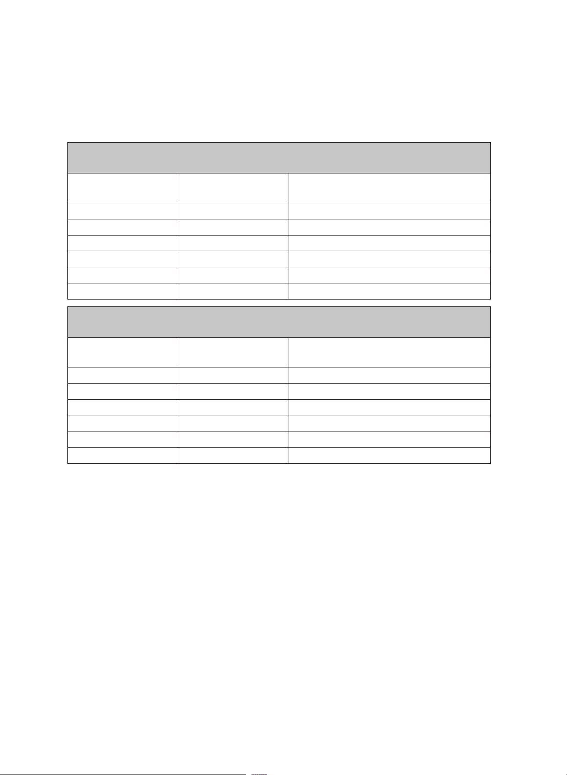
BURNER ORIFICE SIZES AND OUTPUT RATINGS
(LP Gas [Propane] 10 in WCP)
Burner Location BTU Rate
Orifice Size (mm)
Main / sub
RF 7,500 0.7 / 0.42
LF¹ 14,500 In 0.46 / Out 0.74 (2 pcs)
LF² 10,500 0.82 / 0.5
RR 7,500 0.7 / 0.42
LR 10,500 0.82 / 0.5
CTR² 14,500 In 0.46 / Out 0.74 (2 pcs)
BURNER ORIFICE SIZES AND OUTPUT RATINGS
(Natural Gas 5 in WCP)
Burner Location BTU Rate
Orifice Size (mm)
Main / sub
RF 9,500 1.20 / 0.61
LF¹ 18,500 In 0.70 / Out 1.27 (2 pcs)
LF² 13,000 1.41 / 0.68
RR 9,500 1.20 / 0.61
LR 13,000 1.41 / 0.68
CTR² 18,500 In 0.70 / Out 1.27 (2 pcs)
¹30" DTG30M954
²36" DTG36M955
30 English
Installation instructions
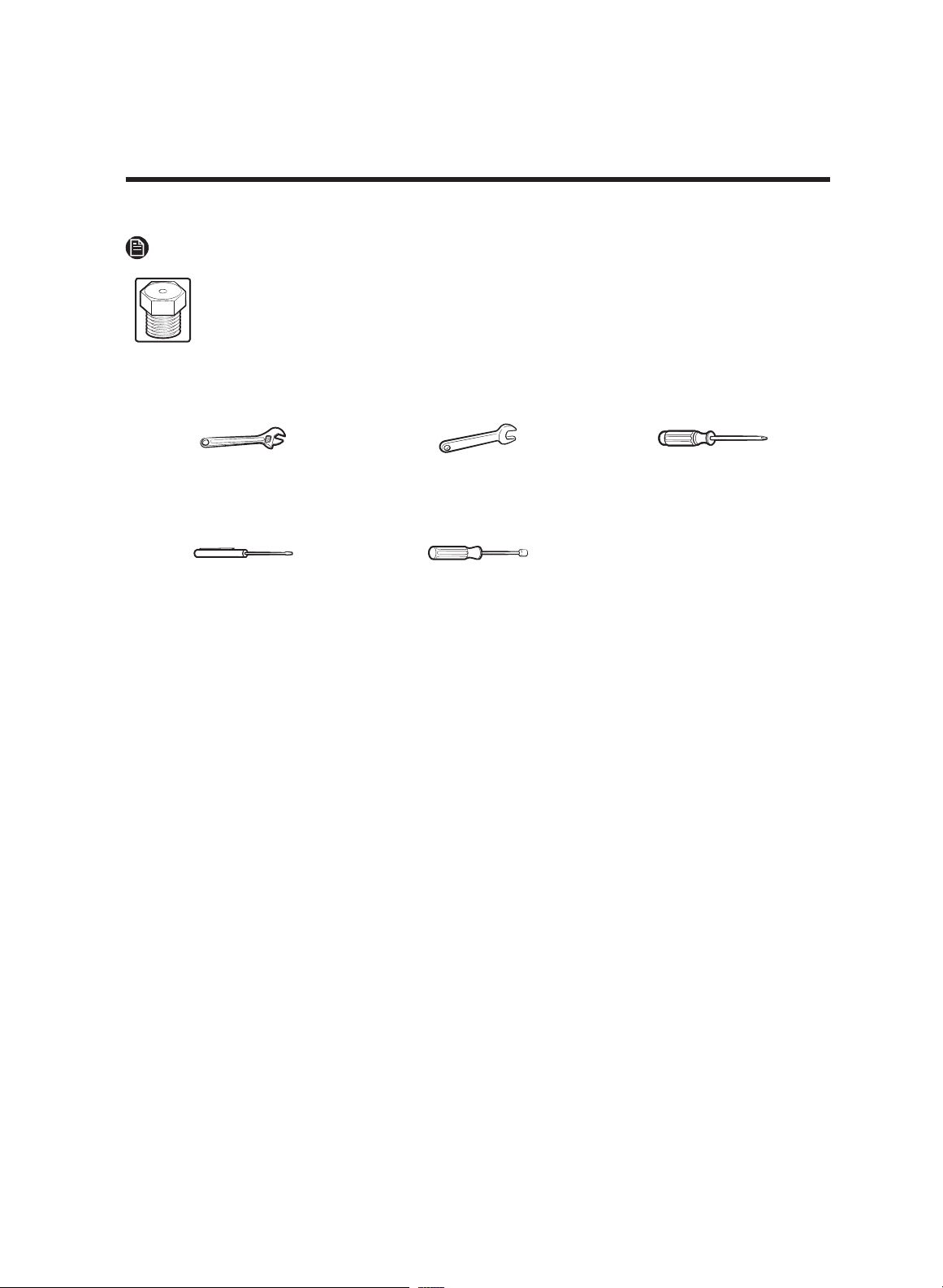
NOTE
115
Orice markings:
115 – Denotes 1.15 mm orice size opening.
Required tools
Adjustable wrench ½” open-end wrench Screwdrivers: Phillips
Small flat-bladed precision
screwdriver
Nut drivers:
9
/32” or 7 mm
To convert the cooktop for LP gas, perform these steps:
1. Disconnect electrical power to the cooktop. (Unplug the cooktop, trip the circuit
breaker, or remove the fuse.)
2. Close the manual shut-off valve to cut the gas supply to the cooktop.
English 31
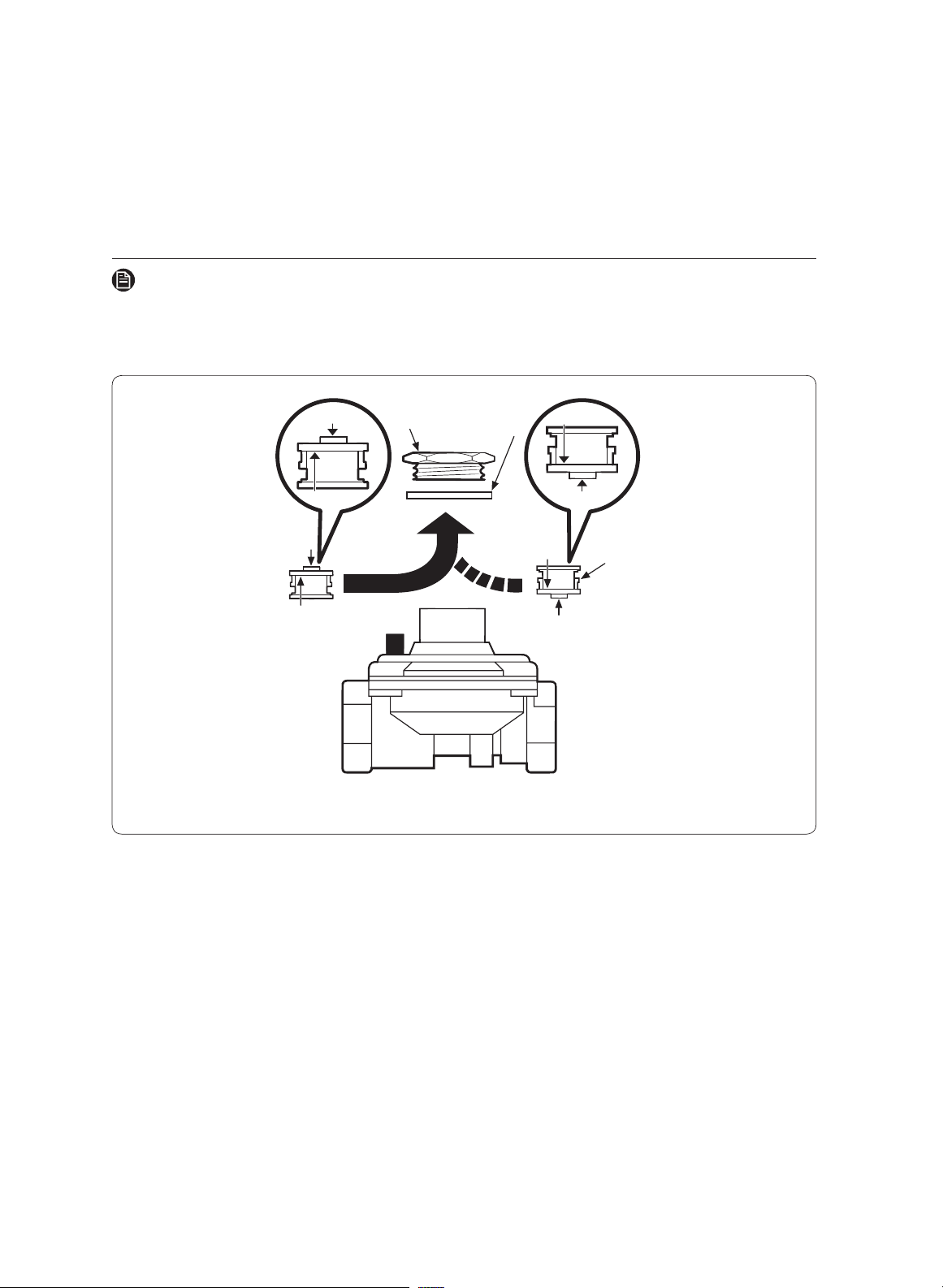
Converting the pressure regulator
NOTE
If you use LP gas, these steps and conversions must be made before adjusting the flames.
1. Using your fingers, turn the cap. And carefully look at the spring retainer to locate the
NAT or LP position.
LP
LP
LP
LP
NAT
NAT
NAT
NAT. Position
L.P./Propane
Position
Pressure Regulator
Spring
Retainer
NAT
Cap
Gasket
LP
2. Rotate the spring retainer 90°, and pull it from the cap. Turn the spring retainer over
so LP shows, re-insert it in the cap, then rotate it 90° into position.
3. Screw the cap back onto the regulator, and tighten the cap.
32 English
Installation instructions
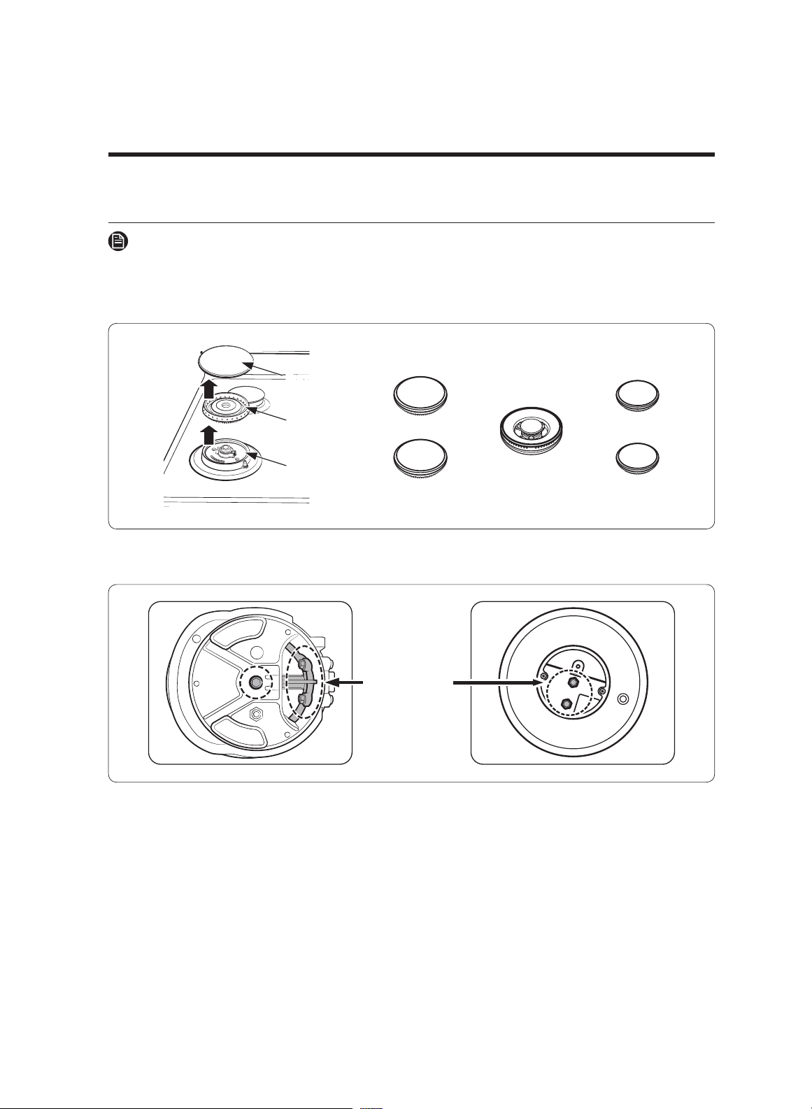
Converting the cooktop burners
NOTE
If you use LP gas, these steps and conversions must be made before adjusting the flames.
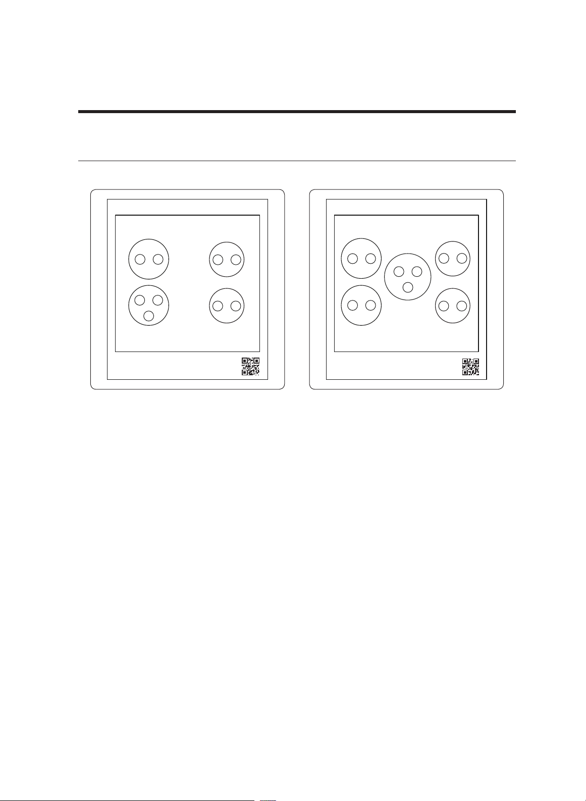
1. Lift off the cooktop burner caps and the cooktop burner heads from the cooktop burner
bases or the cooktop burner cups.
Burner Cap
Burner Head
Burner Base
Cooktop Burner Locations
2. Using a /32” or 7 mm nut driver, remove the burner orifice from the bottom of each
burner cup.
Cooktop Burner
Orifice
English 33
NOTE
Save these orifices and note their positions for future conversions back to natural gas.
3. Locate the LP conversion orifices that were shipped with the cooktop.
4. Identify the proper orifice by orifice size for each of the cooktop burners.
5.
Install the proper orifice in each burner cup, and tighten with a
9
/32” or 7 mm nut driver.
NOTE
Wrongly located orifices could result in dangerous operating conditions and poor
cooking results.
6. Set all burner heads on the same burner bases and cups from which they were
removed. The hole on the side of the burner heads goes over the electrodes. The
heads are correctly installed when they lie flat atop the bases or cups.
7. Set all burner caps atop the burner heads. These also lie flat when installed, ensuring
proper safe operation.
Adjusting low flame setting on cooktop burners
C
heck all burner flames at their l
owest setting. Use these steps to check and adjust the
settings.
NOTE
•
Low-setting adjustments should always be made with two or more burners on at once.
• Call for service when you need to adjust the inner flame of the center burner settings.
1. Turn on two or more cooktop burners, and set them between MED and HI.
2. Quickly turn one of the control knobs counterclockwise to the lowest setting. (If
the flame goes out, adjust the bypass valve on that burner's control valve.
3. Pull the control knob for that burner straight off.
34 English
Installation instructions
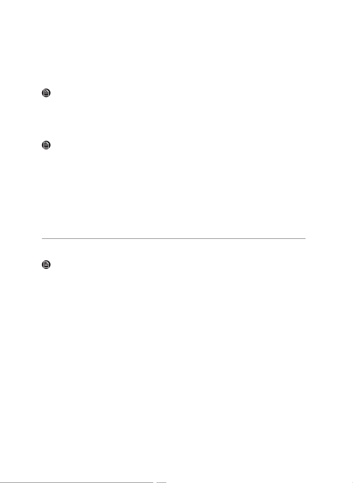
4. With a small, flat-bladed screwdriver, adjust the bypass valve screw in the base of the
valve stem. Turn the bypass valve screw counterclockwise to increase the flame size.
Flat-bladed
screwdriver
Inner flame
bypass screw
Outer flame
bypass screw
Inner flame
bypass screw
Dual valve
5. Replace control knob and recheck the low flame setting.
6. Repeat Step 1 – 5 to check and adjust the low-flame settings on the remaining burners.
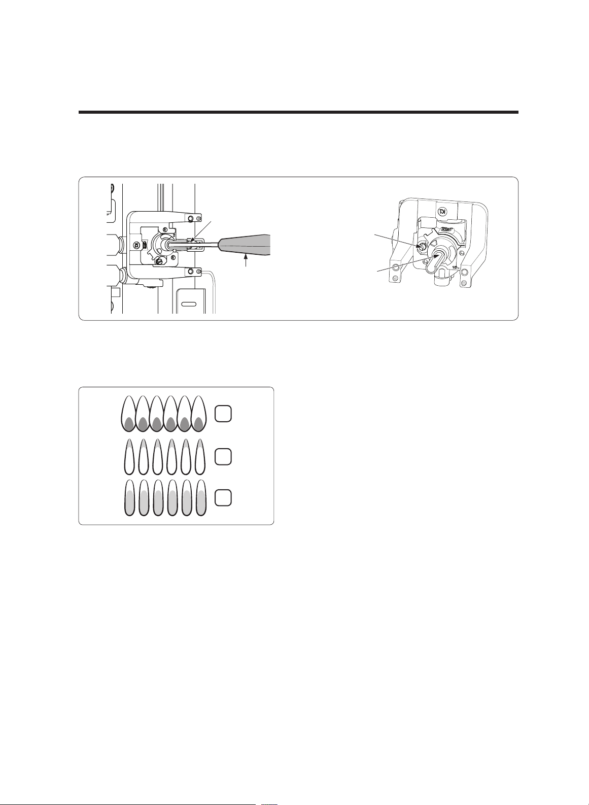
Combustion flame quality
2
3
1
1. Soft blue flames—Normal for
natural gas operation.
2. Yellow tips on outer cones—
Normal for LP gas operation.
3. Yellow flames—Abnormal for
any gas operation. Further
adjustment required.
Additional low-flame check
1. Quickly open and close the cabinet door while the burner is on LO. (If the flame goes
out, increase the low-flame setting, and repeat the test until the flame stabilizes.
2. Quickly turn the knob from HI to the lowest setting. (If the flame goes out at the
lowest setting, increase the low-flame setting, and repeat the test until the flame
stabilizes.
English 35

Dacor ∙ 14425 Clark Avenue, City of Industry, CA 91745 ∙ Phone: (800) 793-0093 ∙ Fax: (626) 403-3130 ∙ www.dacor.com
DG68-00926A-00