Loading ...
Loading ...
Loading ...
8 716 473 071 (2015/04)HydroPower
Installation | 11
Combustion gases
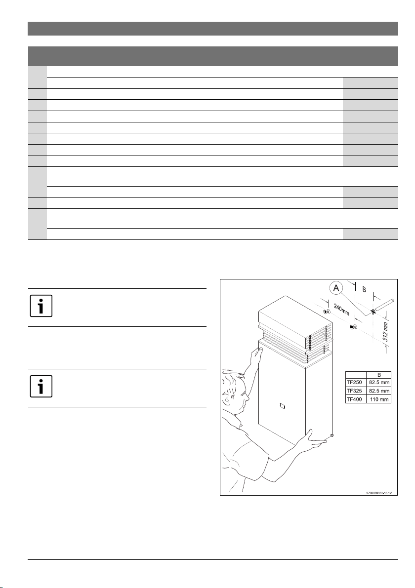
4.3 Hot Water Unit mounting
▶ Fix the appliance vertically, using the fixings appropriate
for the wall material and appliance weight.
Fig. 6 Heater mounting
[A] Appliance upper right corner position
Ref. Item
Minimum
clearances (mm)
a Below eaves, balconies and other projections:
- Appliances over 50 MJ/h input
500
b From the ground, above a balcony or other surface
1)
1) Unless appliance is certified for closer installation
300
c From a return wall or external corner
1)
500
d From a gas meter (M) (see 5.11.5.9 of AS/NZS5601 for vent terminal location of regulator) 1000
e From an electricity meter or fuse box [P] 500
f From a drain pipe or soil pipe 150
g Horizontally from any building structure
1)
or obstruction facing a terminal 500
h From any other flue terminal, cowl, or combustion air intake [T]
1)
500
j Horizontally from an openable window, door, non-mechanical air inlet, or any other opening into a building with the
exception of sub-floor ventilation [W] [D] [T]:
- Appliances up to 150 MJ/h input
500
k From a mechanical air inlet, including a spa blower [I] 1500
n Vertically below an openable window, non-mechanical air inlet, or any other opening into a building with the exception of
sub-floor ventilation [W] [T]
- Appliances over 50 MJ/h input and up to 150 MJ/h input
1000
Table 6
Observe/comply with the minimum
clearances as in AS/NZS5601.
Draw a cross in the wall ( Fig. 6, [A]) to
identify the appliance upper right corner
positioning.
Loading ...
Loading ...
Loading ...