OWNER'S MANUAL
CAUTION
RISKOFELECTRICSHOCK
DONOTOPEN
CAUTION: TO REDUCE THE RISK OF
ELECTRIC SHOCK, DO NOT REMOVE
COVER (OR BACK). NO USER-SERVICEABLE
PARTS INSIDE. REFER SERVICING TO
QUALIFIED SERVICE PERSONNEL.
• Explanation of Graphical Symbols
The lighming flash with arrowhead sylnbol, within an
equilateral triangle, is imended 1o alert you to the
prcscnce of uninsulaled 'dangerous voltage" widlin
the product's enclosure that may be of sullicient
magnitude to conslimte a risk of electric shock to
persons.
The exclamation point within an equilateral triangle
is imended m alelr you m the prc_nce of important
operating andmaintenance/servicing) insmlctkms in
the lileramrc accompanying lhe appliance.
1 Read Instructions All the safety and operating instructions
should be read before the product is operated.
2 Retain Instructions The sali:ty and operating instructions
should be retained lk_rlhture rel'crence.
3 Heed Warnings All warnings on the product and in the
operating instructions should be adhered to.
4 Follow Instructions All operating and use instructions
should be followed.
5 Cleaning Unplug this product l?'om the wall outlet before
cleaning. Do not use liquid cleaners or aerosol cleaners. Use
a damp cloth for cleaning.
6 Attachments Do not use attachments not recommended by
the product manulhcturer as they may cause hazards.
7 Water attd Moisture Do not use this product near water
lor example, near a bath tub. wash bowl. kitchen sink. or
laundry tuh: in a wet basement: or near a swimming pool;
and the like.
8 Accessories Do not place this product on an unstable cart.
stand, tripod, bracket, or table. The product may IMI.
causing serious ii_iury to a child or adult, and serious
damage to the product. Use only with a cart. stand, tripod,
bracket, or table recommended by the manufacturer, or sold
with the product. Any mounting of the product should
lollow the manufacturer's instructions, and should use a
mounting accessory recommended by the manufacturer.
9 A product and cart combination should be moved with care.
Quick stops, excessive li_rce, and mmven
surfaces may cause the product and cart
combiltation to overturn.
10 Ventilation Slots attd openings in the cabinet arc provided
for ventilation and to ensure reliable operation of the
product and to protect it from overheating, and these
openings must not be blocked or covered. The opmfings
should never be blocked by placing the product on a bed.
solm rug, or other similar surl'ace. This product should not
be placed in a built-in installation such its a bookcase or rack
unless proper ventilation is provided or the manuf_cturer's
instructions have been adhered to.
11 Power Sources This product should be operated only from
the type of power source indicated on the marking label. If
you are not sure of the type of power supply to your home.
consult your product dealer or local power company. For
products intended to operate from battery power, or other
sources, refer to the operating instructions.
12 Grounding or Polarization This product may be equipped
with a polarized alternating current line plug (a plug having
one blade wider than the other). This plug will fit into the
power outlet only one way. This is a safety feature. If you
are unable to insert the plug fully into the outlet, try
reversing the plug. If the plug should still fail to fit. contact
your electrician to replace your obsolete outlet. Do not
defeat the sali:ty purpose of the polarized plug.
13 Power-Cord Protection Power-supply cords should be
routed so that they are not likely to be walked on or pinched
by items placed upon or against them, paying particular
attention to cords at plugs, convenience receptacles, and the
point where they exit l]'om the product.
14 Lightning For added protection for this product during a
lightning storm, or when it is left unattended and unused lot
long periods of time. unplug it from the wall outlet and
discotmect the atttenna or cable system. This will prevent
damage to the product due to lightning and powerdine
surges.
15 Power Lines An outside antenna system should not be
located in the vicinity of overhead power lines or other
electric light or power circuits, or where it can fall into such
power lines or circuits. When installing an outside attteuna
system, extreme care should be taken to keep from touching
such power lines or circuits its contact with thmn might be
lhtah
16 Overloading Do not overload wall outlets, extension
cords, or integral convenience receptacles as this can result
in a risk of fire or electric shock.
17 Ohject and Liquid Entry Never push ot_jects of any kind
into this product through openings as they may touch
dangerous voltage points or short<rot parts that could result
in a fire or electric shock. Never spill liquid of any kind on
the product.
18 Servicing Do not attempt to service this product yourself
as opening or removing covers may expose you to
dangerous voltage or other hazards. Refer all servicing to
qualified service persommh
19 Damage Requiring Service Unphlg this product from the
wall outlet and relier servicing to qualified service personnel
under the folhtwing conditions:
a) When the power-supply cord or plug is damaged,
b) If liquid has been spilled, or ohjects have fallen into the
product.
c) If the product hits been exposed to rain or water.
d) Ifthepruductdoesnotoperatenormallybyfl)llowing
theoperatinginstructions.A_ljust only those controls
that are covered by the operating instructions as an
improper attjustmeut of other controls may result in
damage and will oflen require extensive work by a
qualified technician tu resture the product to its normal
operation.
e) If the product has been drupped ur damaged in any
way, and
1) When the product exhibits a distinct change in perfor-
mance - this indicates a need for service.
20 Replacement Parts When replacement parts are required.
be sure the service technician has used replacement parts
specified by the mauulhcturer or have the same
characteristics as the original part. Unauthorized
substitutions may result in fire. electric shock, or other
hazards.
21 Safety Check Upon cumpletion of any service or repairs tu
this product, ask the service technician to perform safety
checks to determine that the product is in proper operating
condition.
22 Wall or Ceiling Mounting The unit should be muunted
to a wall or ceiling only as recommended by the
UlHuuh_ct urer.
23 Heat The product should be situated away ti"om heat
suurces such as radiators, heat registers, stoves, or uther
products (including amplifiers) that produce heat.
Note to CATV system installer:
This reminder is provided to call the CATV systmn installer's
attention to Article 820-40 of the NEC that provides
guidelines for proper grounding and, in particular, specifies
that the cable ground shall be connected to the grounding
system uf the building, as close to the puint of cable entry as
practicah
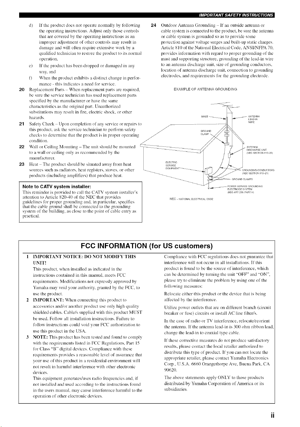
24
f
Outdoor Antenna Grounding If an outside antenna or
cable system is connected to the pruduct, be sure the antenna
ur cable system is gruunded so as to provide some
protection against voltage surges and built-up static charges.
Article 810 uf the National Electrical Code. ANSI/NFPA 70.
provides information with regard to proper grounding of the
mast and supporting structure, grounding of the leaddn wire
to an antenna discharge unit. size of grounding conductors.
location uf antenna discharge unit. connection to grounding
electrodes, and requirements for the grounding electrode.
EXAMPLE OF ANTENNA GROUNDING
GROUND
CLAMP
-- POWEIq_qERVICE GROUNDtNG
ELECTRODE SYSTEM
_NECART 2:3O¸PART H_
NEe NATIONA_ ELE_TRICAL CODE
FCC INFORMATION (for US customers)
1 IMPORTANT NOTICE: DO NOT MODIFY THIS
UNIT!
This product, when installed as indicated in the
instructions contained in this manuah meets FCC
requirements. Modifications not expressly appruved by
Yamaha may void your authority, granted by the FCC. to
use the product.
IMPORTANT: When connecting this product to
accessories and/ur another product use only high quality
shielded cables. Cable/s supplied with this pruduct MUST
be used. Follow all installation instructions. Failure to
fullow instructions could vuid yuur FCC authurization to
use this product in the USA.
NOTE: This product has been tested and louud to comply
with the requirements listed in FCC Regulations. Part 15
lur Class "B" digital devices. Cumpliance with these
requirements provides a reasomdqe level of assurance that
your use of this product in a residential envirunmeut will
not result in harmlid interference with other electronic
devices.
This equipment generales/uses radio frequencies and. if
not installed and used according to the instructiuns ftmnd
in the users manuah may cause interference harmflfl to the
operation of other electronic devices.
Cumpliauce with FCC regulations does not guarantee that
interference will not occur in all installations. If this
product is louud tu be the source of interference, which
can be determined by turning the unit "OFF" and "ON".
please try to eliminate the problem by using one of the
following measures:
Relucate either this product or the device that is being
affected by the interlerence.
Utilize power outlets that are un different branch (circuit
breaker or lilse) circuits or install AC line lilter/s.
In the case of radio or TV interference, relocate/reurieut
the antenna. If the antenna leaddn is 300 uhm ribbon lead
change the lead-in to coaxial type cable.
If these corrective measures do not produce satisfactury
results, please contact the lucal retailer authorized to
distribute this type of product. If you can not locate the
apprupriate retailer, please cuutact Yamaha Electronics
Curp.. U.S.A. 6660 Orangethurpe Ave. Buena Park. CA
90620.
The above statements apply ONLY to those products
distributed by Yamaha Corporation of America or its
subsidiaries.
1 To assure the finest performance, please read this
manual carefully. Keep it in a safe place for future
reference.
2 Install this sound system in a well ventilated, cool,
dry, clean place -- away from direct sunlight, heat
sources, vibration, dust, moisture, and/or cold.
Allow ventilation space of at least 30 cm on the top,
20 cm on the left and right, and 20 cm on the back of
this unit.
3 Locate this unit away from other electrical
appliances, motors, or transformers to avoid
humming sounds.
4 Do not expose this unit to sudden temperature
changes from cold to hot, and do not locate this unit
in a environment with high humidity (i.e. a room with
a humidifier) to prevent condensation inside this
unit, which may cause an electrical shock, fire,
damage to this unit, and/or personal injury.
5 Avoid installing this unit where foreign object may
fall onto this unit and/or this unit may be exposed to
liquid dripping or splashing. On the top of this unit,
do not place:
Other components, as they may cause damage
and/or discoloration on the surface of this unit.
Burning objects (i.e. candles), as they may cause
fire, damage to this unit, and/or personal injury.
Containers with liquid in them, as they may fall
and liquid may cause electrical shock to the user
and/or damage to this unit.
6 Do not cover this unit with a newspaper, tablecloth,
curtain, etc. in order not to obstruct heat radiation. If
the temperature inside this unit rises, it may cause
fire, damage to this unit, and/or personal injury.
7 Do not plug in this unit to a wall outlet until all
connections are complete.
8 Do not operate this unit upside-down. It may
overheat, possibly causing damage.
9 Do not use force on switches, knobs and/or cords.
10 When disconnecting the power cord from the wall
outlet, grasp the plug; do not pull the cord.
11 Do not clean this unit with chemical solvents; this
might damage the finish. Use a clean, dry cloth.
12 Only voltage specified on this unit must be used.
Using this unit with a higher voltage than specified
is dangerous and may cause fire, damage to this
unit, and/or personal injury. YAMAHA will not be
held responsible for any damage resulting from use
of this unit with a voltage other than specified.
13 To prevent damage by lightning, disconnect the
power cord from the wall outlet during an electrical
storm.
We Want You Listening For A Lifetime
14 Do not attempt to modify or fix this unit. Contact
qualified YAMAHA service personnel when any
service is needed. The cabinet should never be
opened for any reasons.
15 When not planning to use this unit for long periods
of time (i.e. vacation), disconnect the AC power plug
from the wall outlet.
16 Be sure to read the "TROUBLESHOOTING" section
on common operating errors before concluding that
this unit is faulty.
17 Before moving this unit, press STANDBY/ON to set
this unit in the standby mode, and disconnect the
AC power plug from the wall outlet.
18 VOLTAGE SELECTOR (Asia and General models
only)
The VOLTAGE SELECTOR on the rear panel of this
unit must be set for your local main voltage BEFORE
plugging into the AC main supply. Voltages are:
Asia model ...................... 220/230-240 V AC, 50/60 Hz
General model .. 110/120/220/230-240 V AC, 50/60 Hz
WARNING
TO REDUCE THE RISK OF FIRE OR ELECTRIC
SHOCK, DO NOT EXPOSE THIS UNIT TO RAIN
OR MOISTURE.
This unit is not disconuected from the AC power source as
long as it is connected to the wall outlet, evenif this unit itself
is turned oil This state is called the standby mode. In this
state, this unit is designed tu consume a very small quantity of
power.
FOR CANADIAN CUSTOMERS
To prevent electric shock, match vdde blade of plug to
wide slot and fully insert.
This Class B digital apparatus complies with Canadian
ICES-003.
IMPORTANT
Please record the serial number of this unit in the space
below.
MODEL:
Serial No.:
The serial number is located on the rear of the unit.
Retain this Owner's Manual in a safe place for filture
reference.
YAMAHA and the Electronic Industries Association's Consmner
Electronics Group want you to get the most om of your
equipment by playing it at a safe level. One that lets the sound
come through loud and clear without amloying blaring or
distortion - and most importantl3;without affecting _<_ur
sensitNe hearing.
Since hearing damage from loud somlds is often
undetectable until it is too late. YAMAHAand the
Electronic Industries Association's Consamer
Electronics Grouprecommend you to avoid
prolonged exposure froln excessi_e xolume levels. LIST£NING__o_,.o
.==
III
FEATURES ............................................................. 2
GETTING STARTED ............................................ 3
Supplied accessories .................................................. 3
Installing batteries in the remote control ................... 3
CONTROLS AND FUNCTIONS ......................... 4
Front panel ................................................................. 4
Remote conlrol ........................................................... 6
Using the remote control ........................................... 8
Front panel display .................................................... 9
Rear panel ................................................................ I I
SPEAKER SETUP ............................................... 12
Speaker placement ................................................... 12
Speaker connections ................................................ 13
CONNECTIONS .................................................. 16
Before comlectiug components ................................ 16
Connecting video components ................................. 17
Connecting audio components ................................. 20
Connecting the antemms .......................................... 22
Connecting the power supply cord .......................... 23
Turning on the power ............................................... 25
AUTO SETUP ....................................................... 26
Introduction .............................................................. 26
Optimizer microphone setup .................................... 26
Starting the setup ..................................................... 27
PLAYBACK .......................................................... 31
Basic operations ....................................................... 31
Selecting sound fiekl programs ............................... 33
Selecting input modes .............................................. 37
TUNING ................................................................ 39
Automatic and manual tuning .................................. 39
Presetting stations .................................................... 40
Selecting preset stations ........................................... 42
Exchanging preset stations ...................................... 43
RECORDING ....................................................... 44
• iv _ "go .g±tt__
SOUND FIELD PROGRAM
DESCRIPTIONS ............................................... 45
For movie/video soulves .......................................... 45
For music sources .................................................... 48
ADVANCED OPERATIONS .............................. 49
Selecting the OSD mode .......................................... 49
Using the sleep timer ............................................... 49
Manually a_/justiog speaker levels ........................... 50
Using the test tone ................................................... 51
SET MENU ............................................................ 52
Using SET MENU ................................................... 53
1 SOUND MENU .................................................... 54
2 INPUT MENU ...................................................... 58
3 OPTION MENU ................................................... 60
REMOTE CONTROL FEATURES ................... 62
Control area ............................................................. 62
Setting manufacturer codes ...................................... 63
Controlling other components ................................. 65
Programming codes from other remote controls ..... 66
Changing source names in the display window ....... 67
Cleming function sets .............................................. 68
Clearing individual lmlctions .................................. 69
ZONE 2 (U.S.A., Canada and Australia
models only) ....................................................... 70
Zone 2 colmectious .................................................. 70
Remote controlling Zone 2 ...................................... 71
EDITING SOUND FIELD PARAMETERS ...... 73
What is a sound field ............................................... 73
Changing parameter settings ................................... 73
SOUND FIELD PARAMETER
DESCRIPTIONS ............................................... 75
TROUBLESHOOTING ....................................... 79
RESETTING THE FACTORY PRESETS ........ 84
GLOSSARY ........................................................... 85
Audio lormats .......................................................... 85
Sound field i>r%rams ............................................... 86
Audio inlZ_rmation ................................................... 86
Video signal information ......................................... 87
SPECIFICATIONS ............................... Back cover
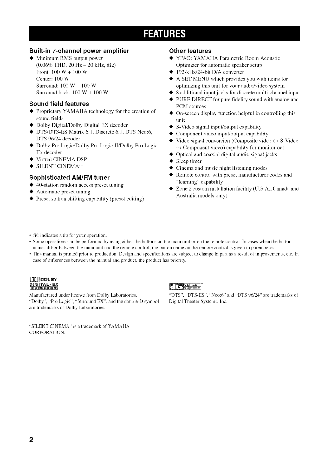
Built-in 7-channel power amplifier
• Minimmn RMS output power
(0.06% THD, 20 Hz - 20 kHz, 8_-_)
Front: 100 W + 100 W
Center: 100 W
Surround: 100 W + 100 W
Surround back: 100 W + 100 W
Sound field features
• Proprietary YAMAHA technology for the creation of
sound fields
• Dolby Digital/Dolby Digital EX decoder
• DTS/DTS-ES Matrix 6.1, Discrete 6.1, DTS Neo:6,
DTS 96124 decoder
• Dolby Pro Logic/Dolby Pro Logic II/Dolby Pro Logic
llx decoder
• Virtual CINEMA DSP
• SILENT CINEMA'"
Sophisticated AM/FM tuner
• 40-station random access preset tuning
• Automatic preset tuning
• Preset station shifting capability (preset editing)
Other features
• YPAO: YAMAHA Parametric Room Acoustic
Optimizer for automatic speaker setup
• 192-kHz/24-bit D/A converter
• A SET MENU which provides you with items for
optimizing this unit for your audio/video system
• 8 additional input jacks for discrete multi-channel input
• PURE DIRECT IUr pure fidelity sound with analog and
PCM sources
• On-screen display function helpfld in controlling this
unit
• S-Video signal input/output capability
• Component video input/output capability
• Video signal conversion (Composite video +->S-Video
--> Component video) capability I_r monitor out
• Optical and coaxial digital audio signal jacks
• Sleep timer
• Cinema and music night listening modes
• Remote control with preset manufacturer codes and
"learning" capability
• Zone 2 custom installation facility (U.S.A., Canada and
Australia models only)
• -",_;'-indicates a tip lot your operatkm.
• Some operations can be perlk)rmed by using either the buttons on the main unit or on the rmnote controh In cases when the button
names differ between the main unit and the remote controh the button nanm on the rmnote control is given in parentheses.
• This manual is printed prior to production. Design and specifications are suhject to change in part as a result of improvelnents, etc. In
case of diffl:rences between the manual and product, the product has priority.
[111_
DIGITAL" EN
Malmlhctured under license from Dolhy Laboratories.
"Dolby", "Pro Logic". "Surround EX'. and the double-D symbol
are trademarks of Dolby Laboratories.
"DTS'. "DTS-ES'. "Neo:6" and "DTS 96124" are tradmnarks of
Digital Theater Systmns. Inc.
"SILENT CINEMA" is a tradmnark of YAMAHA
CORPORATION.
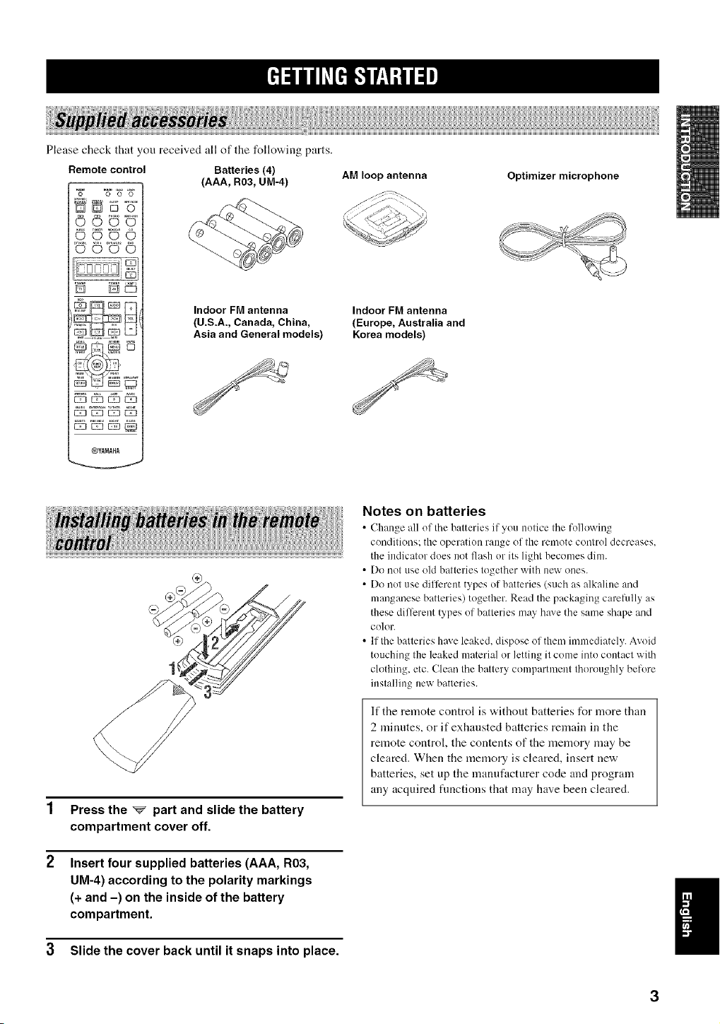
Pleasecheckthatyoureceivedallofthefollowingparts.
Remote control Batteries (4)
N 5 "g"
OQO
@¥ANAHA
(AAA, R03, UM-4)
Indoor FM antenna
(U.S.A., Canada, China,
Asia and General models)
AM loop antenna
Indoor FM antenna
(Europe, Australia and
Korea models)
Optimizer microphone
Press the _ part and slide the battery
compartment cover off.
Insert four supplied batteries (AAA, R03,
UM-4) according to the polarity markings
(+ and -) on the inside of the battery
compartment.
3 Slide the cover back until it snaps into place.
Notes on batteries
• (-_lmnge all of tile b:_tteries if _ou notice tile h)llowing
conditious: the operation range of the remote control decreases.
the indicator does nut flash or its light becomes dim.
• Do not use old batteries together with new ones.
• Do not use different types of batteries (such as alkaline and
manganese batteries) together. Read the packaging careRdly as
these different types of batteries may h_Jvethe same shape and
color.
• If the batteries have leaked, dispose of them immediately. Avoid
touching the leaked material or letting it come into contact with
clothing, etc. Clean the battery compartment thoroughly before
installing new batteries.
If the remote control is without batteries for more than
2 minutes, or if exhausted batteries remain in the
remote control, the contents of the memory may be
cleared. When the memory is cleared, insert new
batteries, set up the manufacturer code and program
any acquired fimctions that may have been cleared.
!
3
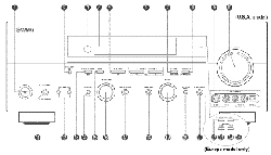
@ @
\
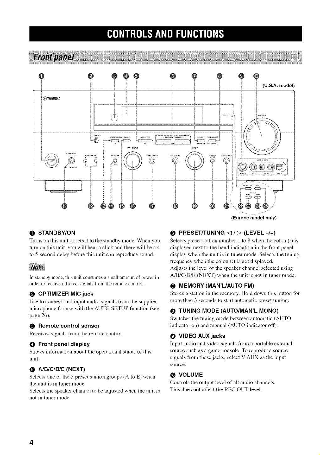
O STANDBY/ON
Turns on this unit or sets it to the staudby mode. When you
turn on this unit, you will hear a click and there will be a 4
to 5-second delay before this unit can reproduce sound.
1i/standby mode, this unit consun/es a small amount of powel_in
order to receive inl'rared-signals f]'om the remote control.
O OPTIMIZER MIg jack
Use to counect and input audio signals from the supplied
microphone for use with the AUTO SETUP fimction (see
page 26).
• Remote control sensor
Receives signals from the remote control.
• Front panel display
Shows iuformatiou about the operational status of this
unit.
O A/B/C/D/E (NEXT)
Selects one of the 5 preset station groups (A to E) when
the unit is in tuner mode.
Selects the speaker channel to be adjusted when the unit is
not in tuner mode.
O PRESET/TUNING <1/_ (LEVEL-/+)
Selects preset station uumber 1 to 8 when the colon (:) is
displayed next to the baud indication in the front panel
display when the unit is in tuner mode. Selects the tuning
frequency when the colon (:) is not displayed.
Adjusts the level of the speaker channel selected using
A/B/C/D/E (NEXT) when the unit is not in tuner mode.
O MEMORY (MAN'L/AUTO FM)
Stores a statiou iu the u]eu]ory. Hold dowu this button for
more than 3 seconds to start automatic preset tuning.
O TUNING MODE (AUTO/MAN'L MONO)
Switches the tuniug u]ode between automatic (AUTO
indicator on) and manual (AUTO indicator off).
O VIDEO AUX jacks
Input audio aud video siguals from a portable exterual
source Sl.lch as a gaule console, To reproduce source
signals from these jacks, select V-AUX as the input
source.
@ VOLUME
Controls the output level of all audio chaunels.
This does not affect the REC OUT level.
• _ PHONES (SILENT CINEMA) jack
Outputs audio signals for private listening with
headphones. When you connect headphones, no signals
are output to the OUTPUT jacks or to the speakers.
All Dolby Digital and DTS audio signals are mixed down
to the left and right headphone channels.
SPEAKERS A/B
Turns on or off tile set of front speakers connected to the A
and/or B terminals on the rear panel each time the
corresponding button is pressed.
@ PRESET/TUNING (EDIT)
Switches tile function of PRESETFFUN]NG <1 / C:>
(LEVEL -/+) between selecting preset station numbers
and tuning.
@ STRAIGHT (EFFECT)
S'a.itches the sound fields off or ou. When STRAIGHT is
selected, input signals (2-channel or multi-channel) are
output directly from their respective speakers without
effect processing.
_) FM/AM
S'a.itches the receptiou baud between FM and AM.
@ PROGRAM
Use to select sound field programs or adjust the bass/treble
balance (in conjunction with TONE CONTROL).
• TONE CONTROL
Use to adjust the bass/treble bahmce for the frout left and
right, center, presence and subwoofer channels (see
page 32).
_) INPUT MODE
Sets the priority (AUTO, DTS, ANALOG) for the type of
signals received when one component is connected to two
or more of this unit's input jacks (see page 37).
@ INPUT selector
Selects the iuput source you want to listeu to or watch.
_1 MULTI CH INPUT
Selects the source counected to the MULTI CH INPUT
jacks. When selected, the MULTI CH INPUT source takes
priority over the source selected with INPUT (or the input
selector buttons on the remote control).
@ PURE DIRECT
Tnrns on or off PURE DIRECT mode (see page 36).
_ol _'_l l : Io11_"lV__l _'q..ll gi#h'_.r_,ll tol _'q.
• Europe model only
_1 RDS MODE/FREQ
Press this buttou "a.hen the uuit is receiving an RDS station
to cycle the display between the PS mode, PTY mode, RT
mode, CT mode (if the station offers those RDS data
services) and/or the frequency display.
_) PTY SEEK MODE
Press this button to set the unit to the PTY SEEK mode.
_) PTY SEEK START
Press this buttou to begin searching for a station after the
desired program type has been selected in the PTY SEEK
mode.
EON
Press this button to select a radio program type (NEWS,
INFO, AFFAIRS, SPORT) to tune in automatically.
5
E_o]_Vll;fo]l_*f__y_Vel_lhffO_Jl[oJ_vl_
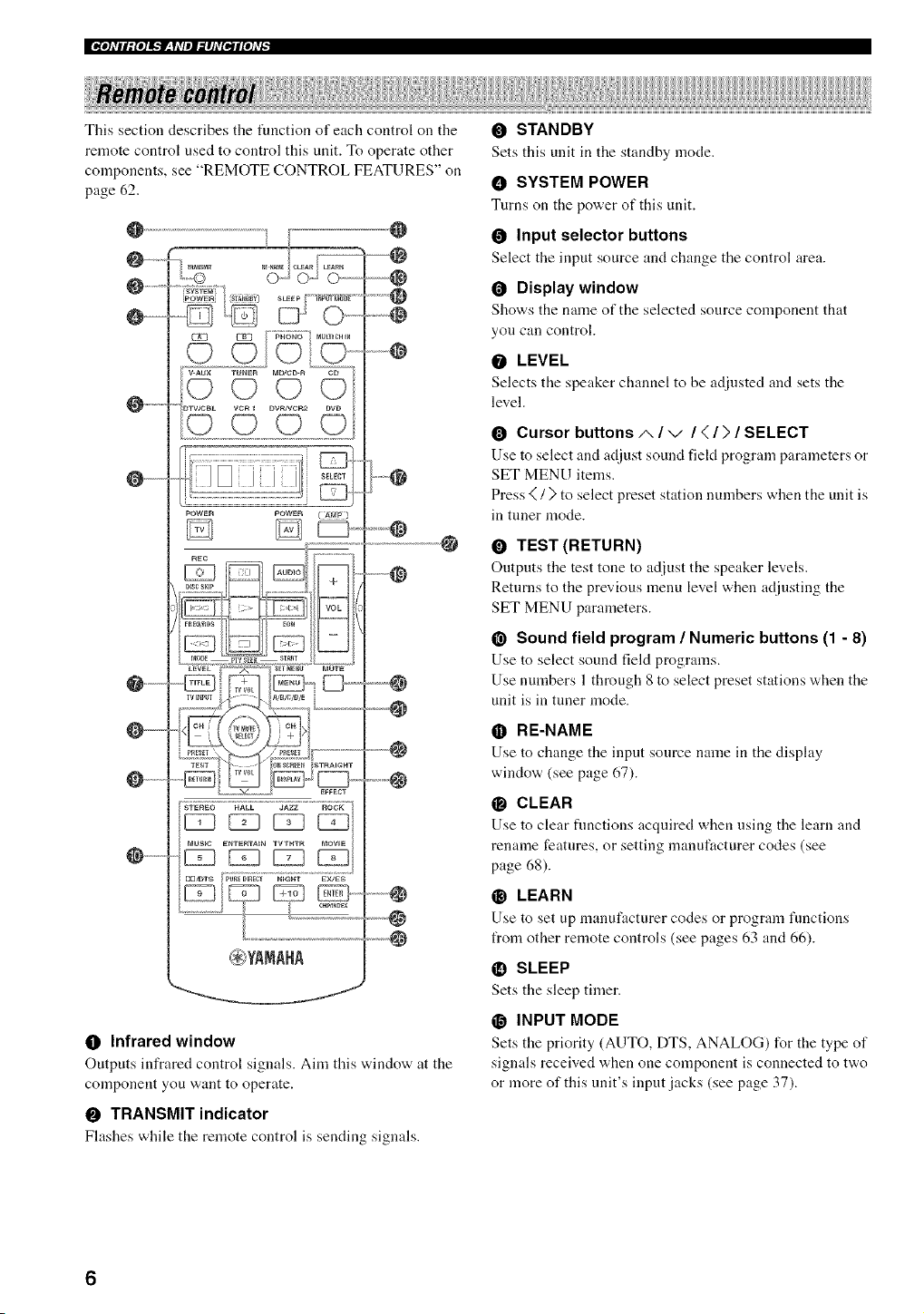
This section describes the tunction of each control on the
remote control used to control this unit. To operate other
components, see "REMOTE CONTROL FEATURES" on
page 62.
@ @
@ .........
0 ......... --@
@........... @
..............
Q .............
POWER POWER
@
0 Infrared window
Outputs infrared control signals. Aim this x_,indow at the
component you want to operate.
O TRANSMIT indicator
Fhtshes while the remote control is sending signals.
O STANDBY
Sets this unit in the standby mode.
O SYSTEM POWER
Turns on the power of this unit.
O Input selector buttons
Select the input source and change the control area.
O Display window
Shows the name of the selected source component that
you can control.
O LEVEL
Selects the speaker channel to he adjusted and sets the
level.
O Cursor buttons/,, / -,/ / < / > / SELECT
Use to select and adjust sound fiekt program parameters or
SET MENU items.
Press _ / ) to select preset station numbers when the unit is
in tuner mode.
O TEST (RETURN)
Ontputs the test tone to adjust the speaker levels.
Returns to the previous menu level when adjusting the
SET MENU parameters.
@ Sound field program / Numeric buttons (1 - 8)
Use to select sound field programs.
Use numbers 1 through 8 to select preset stations when the
unit is in tuner mode.
• RE-NAME
Use to change the input source name in the display
window (see page 67).
@ CLEAR
Use to clear fnnctions acquired when using the learn and
rename features, or setting manufacturer codes (see
page 68).
_) LEARN
Use to set up manuf:tcturer codes or program functions
from other remote controls (see pages 63 and 66).
_l_ SLEEP
Sets the sleep timer.
_1 INPUT MODE
Sets the priority (AUTO, DTS, ANALOG) for the type of
signals received when one component is connected to two
or more of this unit's input jacks (see page 37).
@ MULTI CH IN
Selects MULTI CH INPUT when using an external
decoder (etc.).
• SELECT A/V
Selects another component that you can control
independently of the input component selected with the
input selector buttons.
@ AMP
Selects the AMP mode. You nmst select tile AMP mode to
control the main unit.
_) VOk -/+
Increases or decreases the vohnne level.
@ MUTE
Mutes the sound. Press again to restore the audio output to
the previous vohnne level.
@ SET MENU (A/B/C/D/E)
Activates the SET MENU function.
Selects preset station groups when the unit is in tuner
mode.
ON SCREEN
Selects tile display mode of the on-screen display (OSD)
this unit sends to your video monitor.
@ STRAIGHT (EFFECT)
S'a, itches tile sound fields off or on. When STRAIGHT is
selected, input signals (2-channel or multi-channel) are
output directly from their respective speakers without
effect processing.
i_ EX/ES
Switches between 5.1 or 6.1/7.l-channel playback of
multi-channel software.
@ NIGHT
Turns on or off the night listening modes (see page 36).
PURE DIRECT
Turns on or off PURE DIRECT mode (see page 36).
• Europe model only
• RDS tuning buttons
FREQ/RDS
Press this button "a,hen the unit is receiving an RDS station
to cycle the display between the PS mode, PTY mode, RT
mode, CT mode (if the station offers those RDS data
services) and/or the frequency display.
EON
Press this button to select a radio program type (NEWS,
INFO, AFFAIRS, SPORT) to tune in automatically.
PTY SEEK MODE
Press this button to set the unit to the PTY SEEK mode.
PTY SEEK START
Press this button to begin searching for a station after the
desired program type has been selected in the PTY SEEK
mode.
7
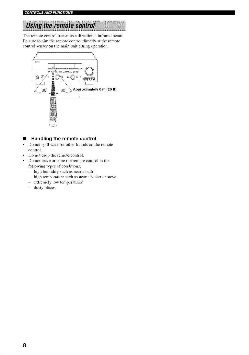
The remote control transmits a directional infrared beam.
Be sure to aim the remote control directly at the remote
control sensor on the main unit during operation.
\
._ Approximately 6 m (20 ft)
Handling the remote control
Do not spill water or other liquids on the remote
control.
Do not drop the remote control.
Do not leave or store the remote control in the
following types of conditions:
high humidity such as near a bath
high temperature such as near a heater or stove
extremely low temperatures
dusty places
=_oldH_foll_]P__yd/eJ_#ld{Bll{old_
(U.S.A., Canada and
Australia models only)
_ (Europe model only)
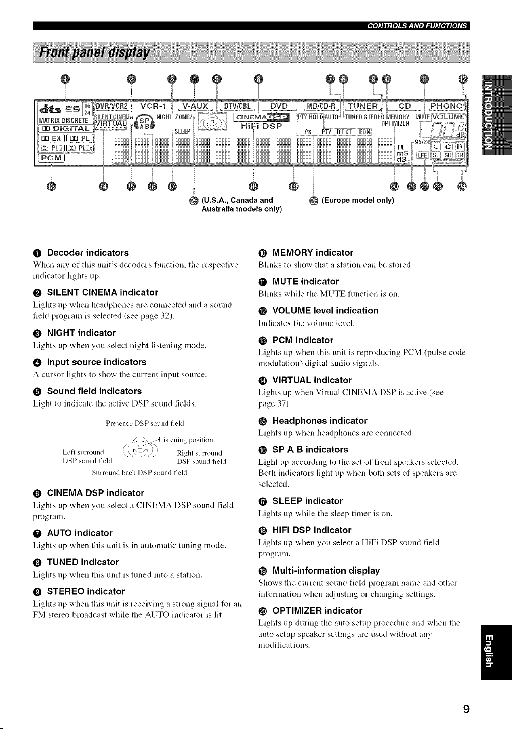
0 Decoder indicators
When any of this unit's decoders function, the respective
indicator lights up.
O SILENT CINEMA indicator
Lights up when headphones are connected and a sound
fiekt program is selected (see page 32).
O NIGHT indicator
Lights up w,hen you select night listening mode.
• Input source indicators
A cursor lights to show the current input source.
O Sound field indicators
Light to indicate the active DSP sound fields.
Presence DSP sound field
i
Z , Listening position
z 3 _ \ /
Lelt sum und /// Rlghl surround
i DSP sound field
DSP SOUlId field
Surround back DSP sound field
O CINEMA DSP indicator
Lights up when you select a CINEMA DSP sound field
program.
O AUTO indicator
Lights up w,hen this unit is in automatic tuning mode.
O TUNED indicator
Lights up v,,hen this unit is tuned into a station.
O STEREO indicator
Lights up when this unit is receiving a strong signal for an
FM stereo broadcast while the AUTO indicator is lit.
@ MEMORY indicator
Blinks to show that a station can be stored.
• MUTE indicator
Blinks while the MUTE function ison.
O VOLUME level indication
Indicates the volume level.
@ PCM indicator
Lights up when this unit is reproducing PCM (pulse code
modulation) digital audio signals.
• VIRTUAL indicator
Lights up when Virtual CINEMA DSP is active (see
page 37).
O Headphones indicator
Lights up ,_,hen headphones are connected.
@ SP A B indicators
Light up according to the set of front speakers selected.
Both indicators light up when both sets of speakers are
selected.
O SLEEP indicator
Lights up while the sleep timer is on.
@ HiFi DSP indicator
Lights up "a,hen you select a HiFi DSP sound field
program.
@ Multi-information display
Show, s the current sound field program mmae and other
information when adjusting or changing settings.
OPTIMIZER indicator
Lights up during the auto setup procedure aiKt when the
auto setup speaker settings are used without any
modifications.
9
@ 96/24 indicator
Lights up when a DTS 9(,/24 signal is input to this unit.
• LFE indicator
Lights up when the input signal contains the LFE signal.
_) Input channel indicators
Indicate tile channel components of tile current digital
input signal.
_) Presence and surround back speaker
indicators
Indicate the connection of presence and/or surround back
speakers when using the SPEAKER LEVEL setting (see
page 56).
ZONE 2 indicator
(U.S.A., Canada and Australia models only)
Lights up when Zone 2 power is on.
_) RDS indicators
(Europe model only)
The name(s) of tile RDS data offered by tile currently
received RDS station light(s) up.
EON lights up when an RDS station that offers the EON
data service is being received.
tYI'Y HOLD lights up while searching for stations in the
tYI'Y SEEK mode.
10
e e e e e
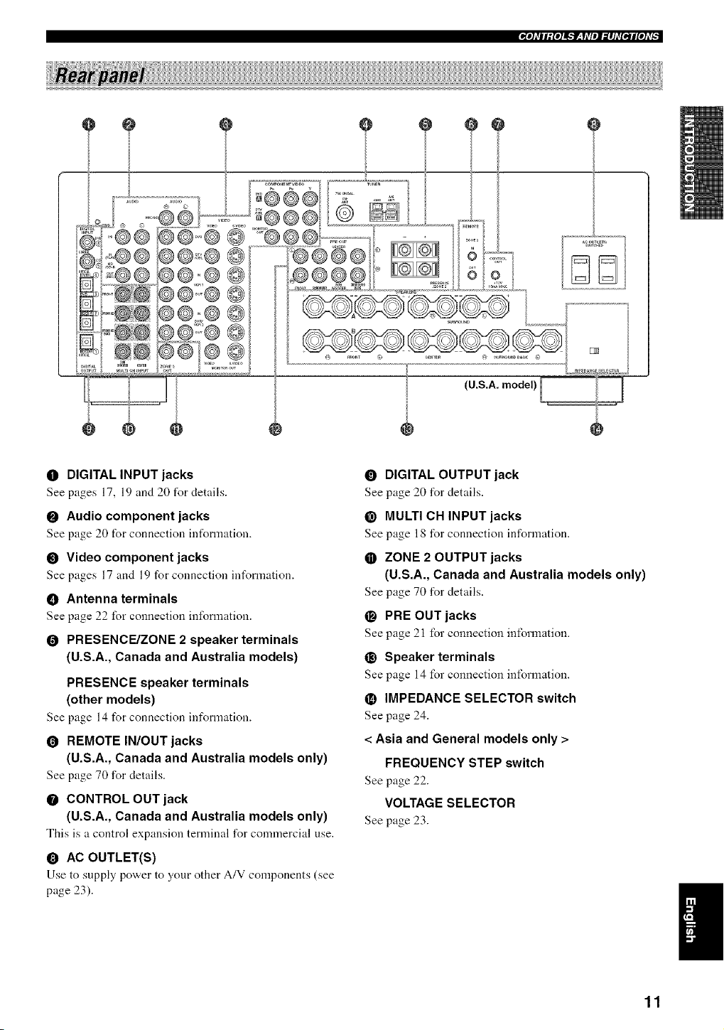
0 DIGITAL INPUT jacks
See pages 17, 19 and 20 for details.
0 Audio component jacks
See page 20 for connection information.
0 Video component jacks
See pages 17 and 19 for connection int_rmation.
• Antenna terminals
See page 22 for connection information.
O PRESENCE/ZONE 2 speaker terminals
(U.S.A., Canada and Australia models)
PRESENCE speaker terminals
(other models)
See page 14 for connection information.
REMOTE IN/OUT jacks
(U.S.A., Canada and Australia models only)
See page 70 for details.
CONTROL OUT jack
(U.S.A., Canada and Australia models only)
This is a control expansion terminal for commercial use.
0 AC OUTLET(S)
Use to supply power to your other A/V components (see
page 23).
DIGITAL OUTPUT jack
See page 20 for details.
@ MULTI CH INPUT jacks
See page 18 for connection information.
ZONE 2 OUTPUT jacks
(U.S.A., Canada and Australia models only)
See page 70 for details.
O PRE OUT jacks
See page 21 for connection information.
@ Speaker terminals
See page 14 for connection information.
IMPEDANCE SELECTOR switch
See page 24.
< Asia and General models only >
FREQUENCY STEP switch
See page 22.
VOLTAGE SELECTOR
See page 23.
11
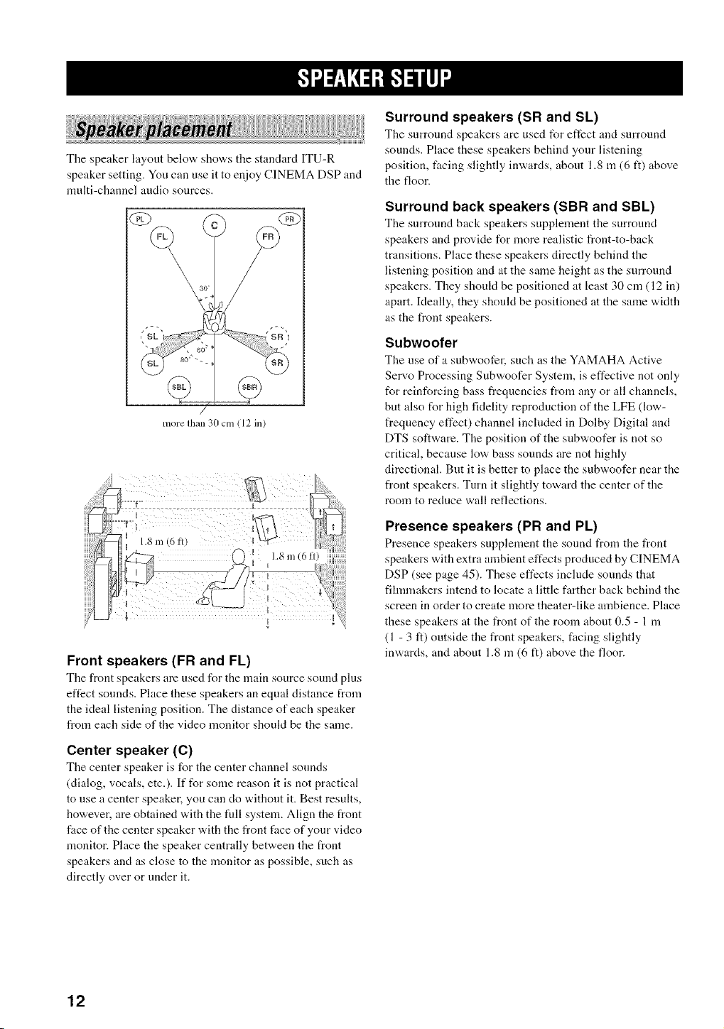
The speaker layout below' show,'s the standard ITU-R
speaker setting. You can use it to enjoy CINEMA DSP and
nmlti-channel audio sources.
iii{i ili !;iISurroandspeakersandSL
The surround speakers are used for effect and surround
sounds. Place these speakers behind your listening
position, thcing slightly inw,'ards, about 1.8 m (6 ft) above
the floor.
/
more Ihan 30 cm ( 12 in
I
1.8
m (6 ll) i
I
I I
Front speakers (FR and FL)
Tile front speakers are used for the main source sound plus
effect sounds. Place these speakers an equal distance from
the ideal listening position. The distance of each speaker
from each side of the video monitor should be the same.
Surround back speakers (SBR and SBL)
The surround back speakers supplement the surround
speakers and provide for more realistic front-to-back
transitions. Place these speakers directly behind the
listening position and at the same height as the surround
speakers. They should be positioned at least 30 cm (12 in)
apart. Ideally, they should be positioned at the same width
as the front speakers.
Subwoofer
The use of a subv,,oofer, such as the YAMAHA Active
Servo Processing Subwoofer System, is effective not only
for reinforcing bass frequencies from any or all channels,
but also for high fidelity reproduction of the LFE (low-
frequency effect) channel included in Dolby Digital and
DTS software. The position of the subwoofer is not so
critical, because low bass sounds are not highly
directional. But it is better to place the subwoofer near the
front speakers. Turn it slightly toward the center of the
room to reduce wall reflections.
Presence speakers (PR and PL)
Presence speakers supplement the sound from the front
speakers with extra anabient effects produced by CINEMA
DSP (see page 45). These effects include sounds that
filmmakers intend to locate a little farther back behind the
screen in order to create more theater-like ambience. Place
these speakers at the front of the room about 0.5 - 1 m
(1 - 3 It) outside the front speakers, facing slightly
inwards, and about 1.8 in (6 ft) above the floor.
Center speaker (C)
The center speaker is for the center channel sounds
(dialog, vocals, etc.). If for some reason it is not practical
to use a center speaker, yon can do "a,ithont it. Best results,
however, are obtained w,ith the full system. Align the front
face of the center speaker with the front face of your video
monitor. Place the speaker centrally between the front
speakers and as close to the monitor as possible, such as
directly over or under it.
12
1+IRflf+il-'l-.'ilq
Be sure to connect the left channel (L), right channel (R),
"+" (red) and .... (black) properly. If the connections are
faulty, no sound will be heard from the speakers, and if the
polarity of the speaker connections is incorrect, the sound
will be unnatural and lack bass.
t'O'alllil'olAR
• If you will use 6 ohm speakers, be sure to set
this unit's speaker impedance setting to 6
ohms before using (see page 24).
• Before connecting tile speakers, make sure that tile
power of this unit is off.
• Do not let the bare speaker wires touch each other or do
not let them touch any metal part of this unit. This
could damage this unit and/or speakers.
• Use magnetically shielded speakers. If this type of
speakers still creates the interference with the monitor.
place the speakers away from the monitor.
A speaker cord is actually a pair of insulated cables
running side by side. One cable is colored or shaped
differently, perhaps with a stripe, groove or ridges.
Connect the striped (grooved, etc.) cable to the "+" (red)
terminals on this unit and your speaker. Connect the plain
cable to the "-" (black) terminals.
10 mm (_)
2
1 Remove approximately 10 mm (318") of
insulation from the end of each speaker
cable.
2 Twist the exposed wires of the cable together
to prevent short circuits.
3 Unscrewthe knob.
4 Insert one bare wire into the hole in the side
of each terminal.
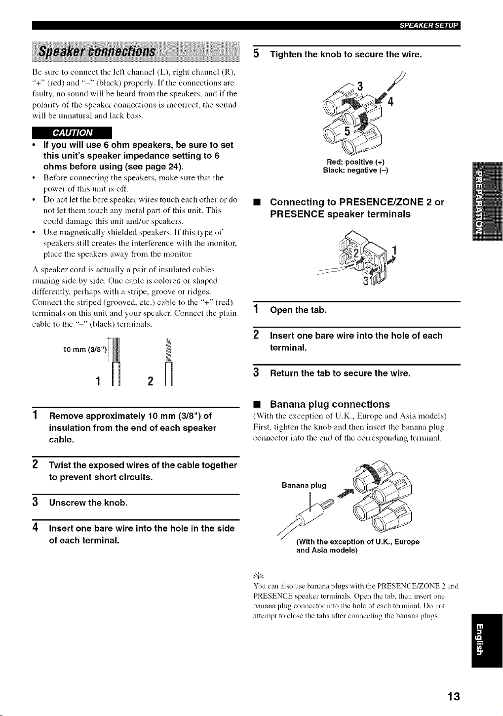
5 Tighten the knob to secure the wire.
3 /
Red: positive (+)
Black: negative (-)
• Connecting to PRESENCE/ZONE 2 or
PRESENCE speaker terminals
1 Open the tab.
2 Insert one bare wire into the hole of each
terminal.
3 Return the tab to secure the wire.
• Banana plug connections
(With the exception of U.K., Europe and Asia models)
First, tighten the knob and then insert the banana plug
connector into the end of the corresponding terminal.
Banana plug
{With the exception of U.K., Europe
and Asia models)
You can alsouse banana plugs with the PRESENCE/ZONE 2 and
PRESENCE speaker terminals. Open the tab. then insert one
banana plug connector into the hole of each terminah Do not
attempt to close the tabs alter connecting the banana plugs.
13

l+--l+iRf+<.i+i+--I..-ii+,_
(U.S.A. model)
Subwoofer Presence speakers
system Right Left
2 3
Right Left
Front speakers (A)
Front 8
speakers Center
(B) speaker
Surround speakers
Right Left
4!!
G
9 10
Right Left
Surround back
speakers
You can connect both surround back and presence speakers to this unit. but they do not output sound simultaneously.
• The surround back speakers output the surround back channel included in Dolby Digital EX and DTS-ES software and only
operate when the Dolby Digital EX or DTS-ES decoder is turned on.
• The presence speakers output ambient elli:cts created by the DSP sound fields. They do not output sound when other sound fields
are selected.
14
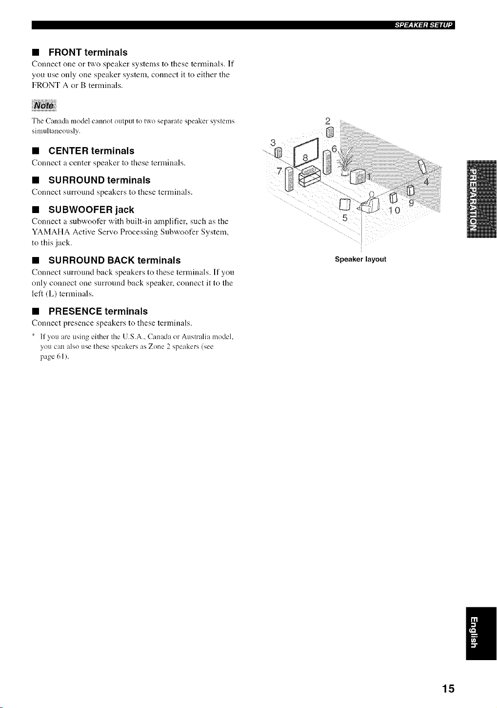
• FRONT terminals
Conuect one or two speaker systems to these terminals. If
you use only one speaker system, connect it to either the
FRONT A or B terminals.
The Canada model cannot output to two separate speaker systems
simultaneously.
• CENTER terminals
Connect a center speaker to these terminals.
• SURROUND terminals
Connect surround speakers to these terminals.
• SUBWOOFER jack
Connect a snbwoofer with built-in amplifier, such as the
YAMAHA Active Servo Processing Subwoofer System,
to this jack.
• SURROUND BACK terminals
Connect surround back speakers to these temfinals. It" you
only connect one surround back speaker, connect it to the
left (L) terminals.
• PRESENCE terminals
Connect presence speakers to these terminals.
' If you are using either the U.S.A.. Canada or Australia model.
you can also use these speakers as Zone 2 speakers (see
page 61 ).
Speaker layout
15
[_:TIjl[o]AvA
Do not connect this unit or other components to the mains
power until all connections between components are
complete.
• Cable indications
For analog signals
lefl analog cables °_'-P_'.k
righl analog cables _1-
For digital signals
oplical cables _av(L o )
coaxial cables _1_,1 _ >
For video signals
video cables _<]_L
S-Video cables <ills
• Analog jacks
You can input analog signals from audio components by
connecting audio pin cable to the analog jacks on this unit.
Connect red plugs to the right jacks and white plugs to the
left jacks.
• Digital jacks
This unit has digital jacks for direct transmission of digital
signals through either coaxial or fiber optic cables. You
can use the digital jacks to input PCM, Dolby Digital and
DTS bitstreams. When you connect components to both
the COAXIAL and OPTICAL jacks, priority is given to
the input signals from the COAXIAL jack. All digital
input jacks are compatible with 96-kHz sampling digital
signals.
This unit handles digital and analog signals independently. Thus
audio signals input to the analog .jacks are only output to the
analog OUT (REC)jacks. Likewise audio signals input to the
digital (OPTICAL or COAXIAL) jacks are only output to the
DIGITAL OUTPUT jack.
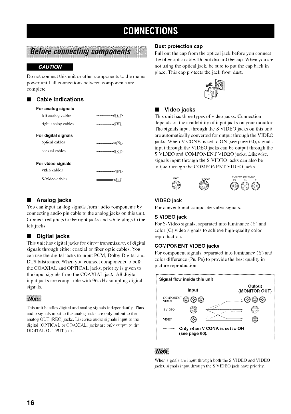
Dust protection cap
Pull out the cap from the optical jack before you connect
the fiber optic cable. Do not discard the cap. When you are
not using the optical jack, be sure to put the cap back in
place. This cap protects the jack from dust.
• Video jacks
This unit has three types of video jacks. Connection
depends on the availability of input jacks on your monitor.
The signals input through the S VIDEO jacks on this unit
are automatically converted for output through the VIDEO
jacks. When V CONV. is set to ON (see page 60), signals
input through the VIDEO jacks can be output through the
S VIDEO and COMPONENT VIDEO jacks. Likewise,
signals input through the S VIDEO jacks can also be
output through the COMPONENT VIDEO .jacks.
COMPONENT VIDEO
VIDEO SV_gEO P_ PB g
@ @ ©@e
VIDEO jack
For conventional composite video signals.
S VIDEO jack
For S-Video signals, separated into luminance (Y) and
color (C) vMeo signals to achieve high-quality color
reproduction.
COMPONENT VIDEO jacks
For component signals, separated into luminance (Y) and
color difference (PB, PR) to provide the best quality in
picture reproduction.
r- ..................................................................................................... ,
Signal flow inside this unit
Output
Input (MONITOR OUT)
VIDEOCOMPONENT@@@
S VIDEO
VIDEO .,
iii ii iii
When signals are input through both the S VIDEO and VIDEO
jacks, signals input through the S VIDEO jack have priority.
16
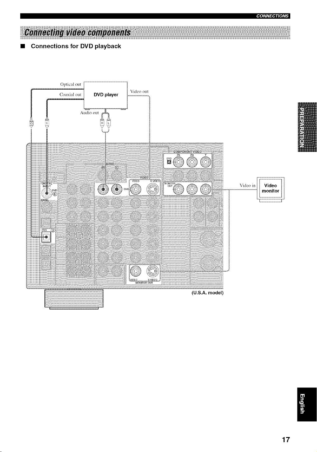
• Connections for DVD playback
Optical out
! Coaxial oul
DVD player
Video oul
Vkleo in
(U.S.A. model)
_otl'll'l_PIIPtl'b
17
1
|_"tfll'l_ql["tl'_
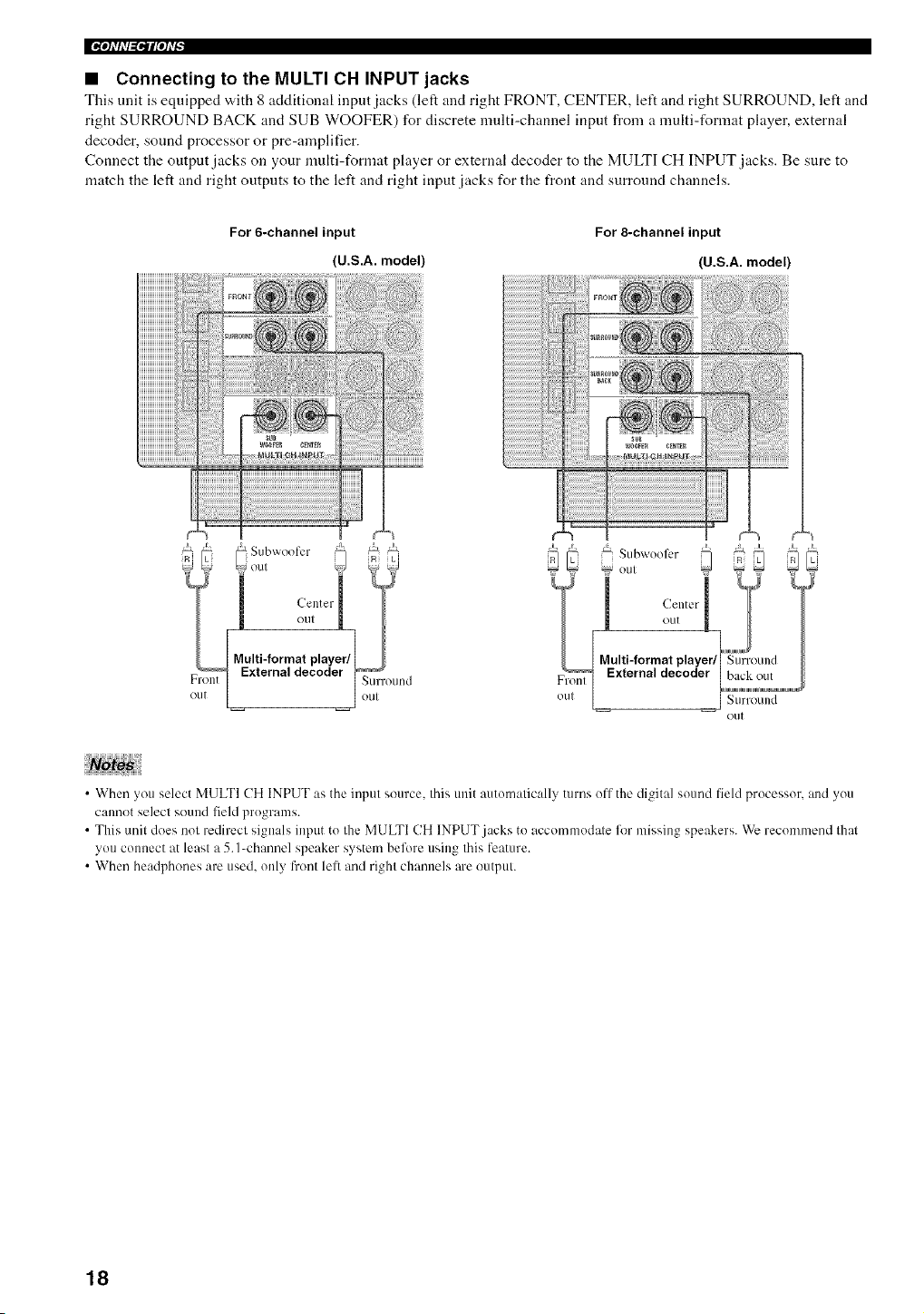
• Connecting to the MULTI CH INPUT jacks
This unit is equipped "a,ith 8 additional input jacks (left and right FRONT, CENTER, left and right SURROUND, left and
right SURROUND BACK and SUB WOOFER) for discrete multi-channel input from a multi-format player, external
decoder, sound processor or pre-amplifier.
Connect the output jacks on your multi-format player or external decoder to the MULTI CH INPUT jacks. Be sure to
match the left and right outputs to the left and right input jacks for the front and surround channels.
For 6-channel input
(U.S.A. model)
For 8-channel input
(U.S.A. model)
Multi-format player/['mm_'_"_(!Surr(Ellld
External decoder / hack out I
o,. I
out
• When you select MULTI CH INPUT as the input source, this unit automatically turns off the digital sound field processor, and you
cannot select sound field programs.
• This unit does not redirect signals input to the MULTI CH INPUT.jacks to accommodate for missing speakers. We recommend that
you connect at least a 5. I_channel speaker system before using this feature.
• When headphones are used. only front lefi and right channels are output.
18
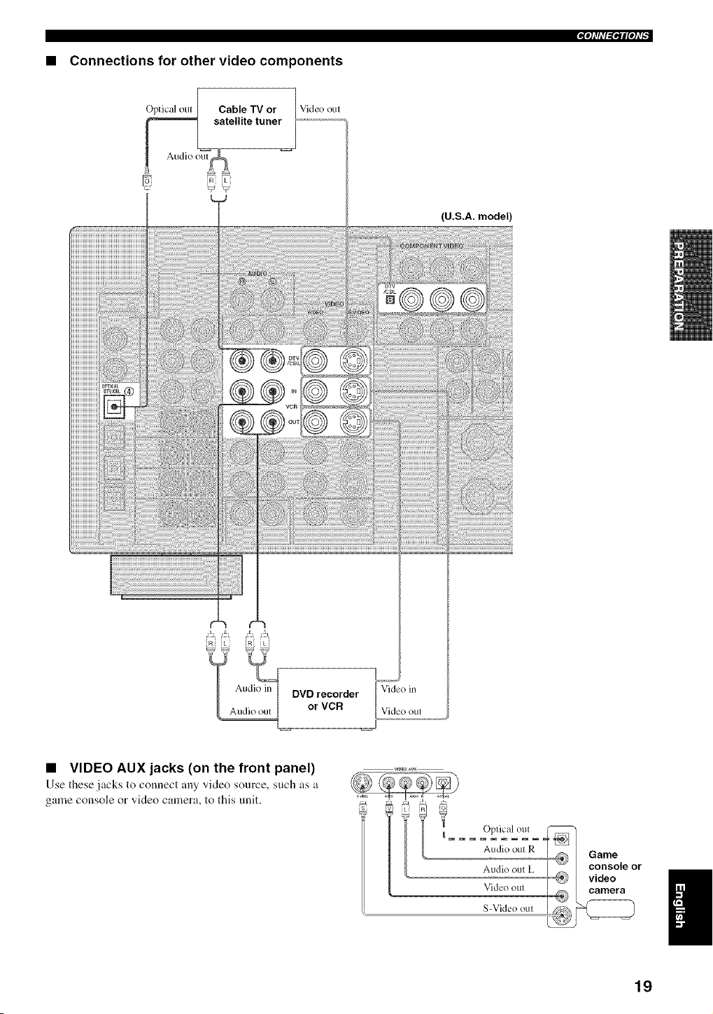
• Connections for other video components
O_Cable TV or 1
atellite tuner_ ..................................
Audio out_
4
Video out
(U.S.A. model)
DVD recorder Video in
or VCR Video out
• VIDEO AUX jacks (on the front panel)
Use these jacks to connect any video source, such as a
game console or video camera, to this unit.
i
Audio out R Game
I _ console or
Audio out L _ video n
Video oul camera
il
19
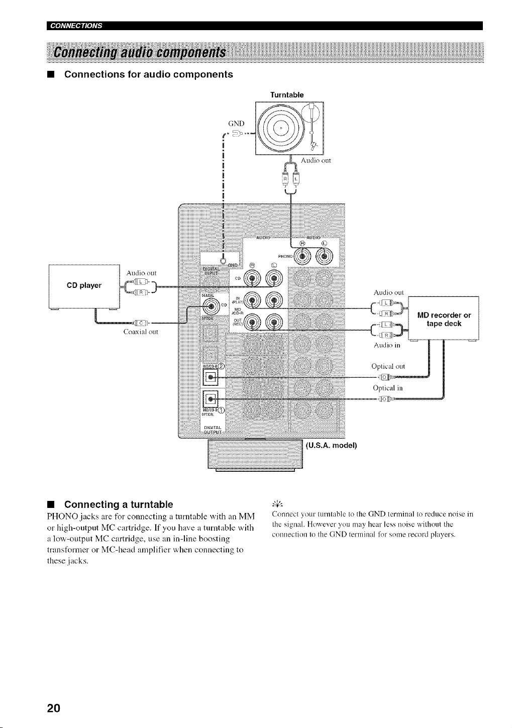
• Connections for audio components
CD player
Turntable
|
m
m
|
Audio oul
Coaxi;t] ou[
Audio {)Ell
(U.S.A. model)
Audk) oul
ME}recorder or
tape deck
• Connecting a turntable
PHONO jacks are for connecting a turntable with an MM
or high-output MC cartridge. If you have a turntable with
a low-output MC cartridge, use an in-line boosting
transformer or MC-head amplifier when connecting to
these jacks.
Connect your turntable to the GND terminal to reduce noise in
the signah However you may hear less noise without the
connection to the GND terminal lk)r some record players.
2O
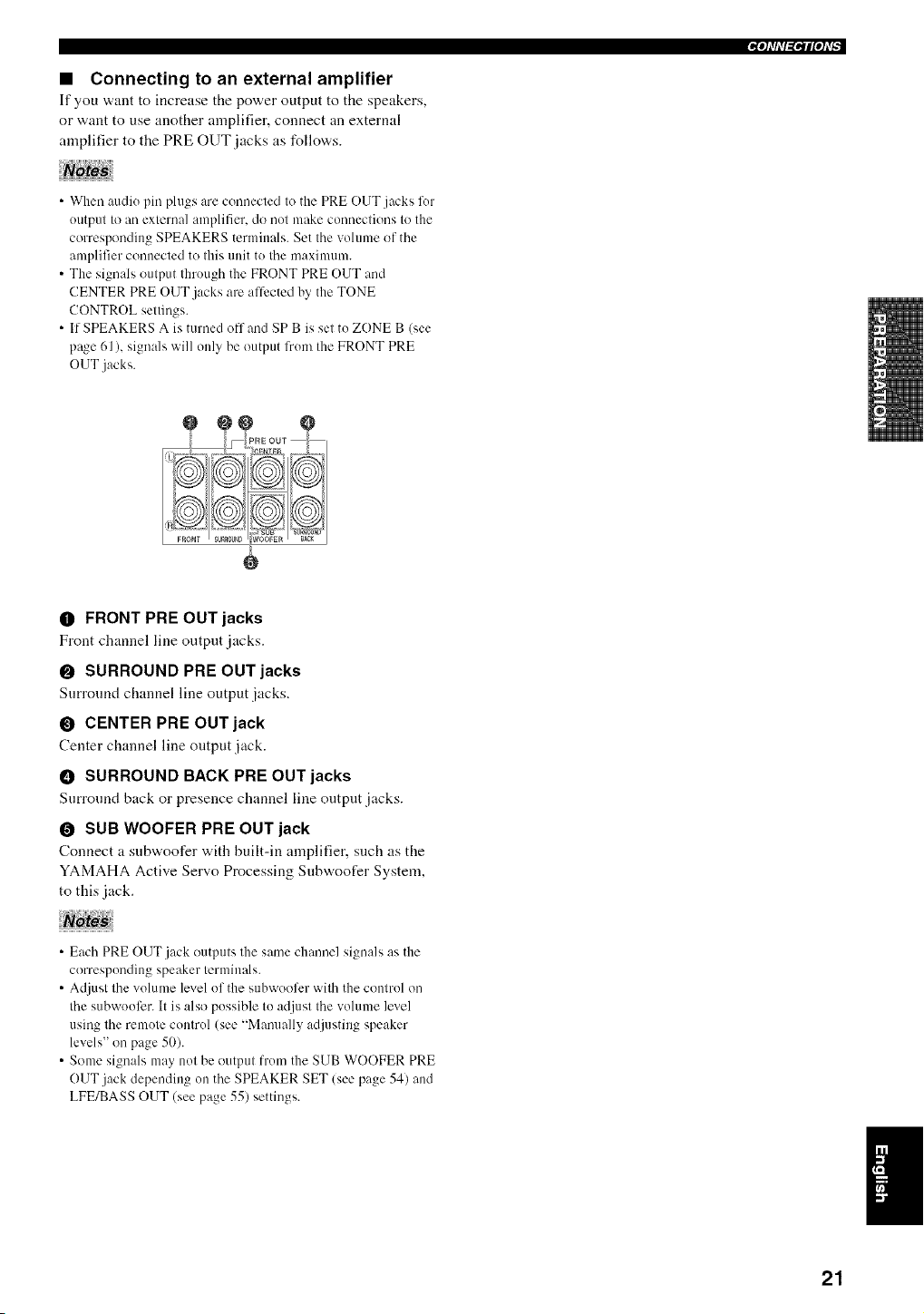
• Connecting to an external amplifier
If you "a,:mt to increase tile power output to tire speakers,
or want to use another amplifier, connect an external
amplifier to the PRE OUT jacks as follows.
• When audiu pill plugs are conuected to the PRE OUT jacks for
output to an external amplifier, do not make connections to the
corresponding SPEAKERS terminals. Set the volume of the
amplifier connected to this unit to the maximum.
• The signals output thruugh the FRONT PRE OUT and
CENTER PRE OUT jacks ale affected by the TONE
CONTROL settings.
• If SPEAKERS A is turned off and SP B is set to ZONE B (see
page 61 ), signals will only be output frun/the FRONT PRE
OUT jacks.
O FRONT PRE OUT jacks
Front channel line output jacks.
O SURROUND PRE OUT jacks
Surround channel line output jacks.
O CENTER PRE OUT jack
Center channel line output jack.
• SURROUND BACK PRE OUT jacks
Surround back or presence channel line output jacks.
O SUB WOOFER PRE OUT jack
Connect a subw,oofer with built-in amplifier, such as the
YAMAHA Active Servo Processing Subwoofer System,
to this jack.
• Each PRE OUT jack outputs the same channel signals as the
corresponding speaker terminals.
• Adjust the volume level of the subwoofcr with the control oi/
the subwouli_r. It is also possible to adjust the volume level
using the remote control (see "Manually adjusting speaker
levels" on page 50).
• Some signals may not be output from the SUB WOOFER PRE
OUT jack depending on the SPEAKER SET (see page 54) and
LFE/BASS OUT (see page 55) settings.
21
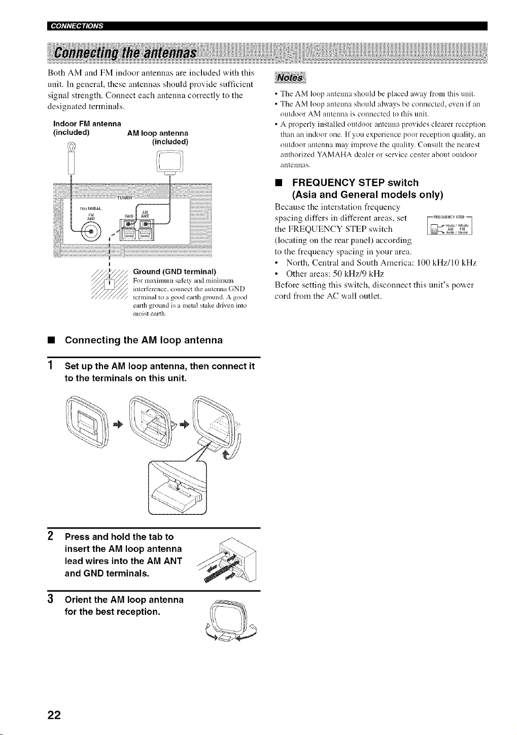
II'_qflfl_ql['h'_
Both AM and FM indoor antennas are included with this
unit. In general, these antennas should provide sufficient
signal strength. Connect each antenna correctly to the
designated terminals.
Indoor FM antenna
(included) AM loop antenna
(included)
Ground (GND terminal)
For m_ximum salcty mM mininmn;
interi_srcnce, connect the anlenna GND
terminal to a good earth ground. A good
earth ground is a metal slake driven into
moist earth.
• The AM loop antenna should he placed away from this unit.
• The AM loop antenna should always be connected, even if an
outdoor AM antenna is connected to this unit.
• A properly installed outdoor antenna provides clearer reception
than an indoor one. If you experience poor reception quality, an
outdoor antenna may improve the quality. Consult the nearest
authorized YAMAHA dealer or service center about outdoor
antennas.
• FREQUENCY STEP switch
(Asia and General models only)
Because the interstation frequency
spacing differs in different areas, set
the FREQUENCY STEP switch
(locating on the rear panel) according
to the freqnency spacing in your area.
• North, Central and South America: 100 kHz/10 kHz
• Other areas: 50 kHz/9 kHz
Before setting this switch, disconnect this unit's power
cord from the AC wall outlet.
• Connecting the AM loop antenna
1 Set up the AM loop antenna, then connect it
to the terminals on this unit.
Press and hold the tab to
insert the AM loop antenna
lead wires into the AM ANT
and GND terminals.
3 Orient the AM loop antenna
for the best reception.
22
• Connecting the AC power cord
Plug the po'a, er cord into an AC wall outlet.
• AC OUTLET(S) (SWITCHED)
U.K. and Australia models ............................. 1 OUTLET
Korea model .............................................................. None
Other models ................................................. 2 OUTLETS
Use these outlets to connect the power cords from your
other components to this unit. Power to the AC
OUTLET(S) is controlled by this unit's STANDBY/ON
(or SYSTEM POWER and STANDBY). The outlet(s)
supply power to any connected component whenever this
unit is turned on. The maximum power (total power
consumption of components) that can be connected to the
AC OUTLET(S) is:
China, Asia and General models ............................. 50 W
Korea model ................................................................ N/A
Other models ........................................................... 100 W
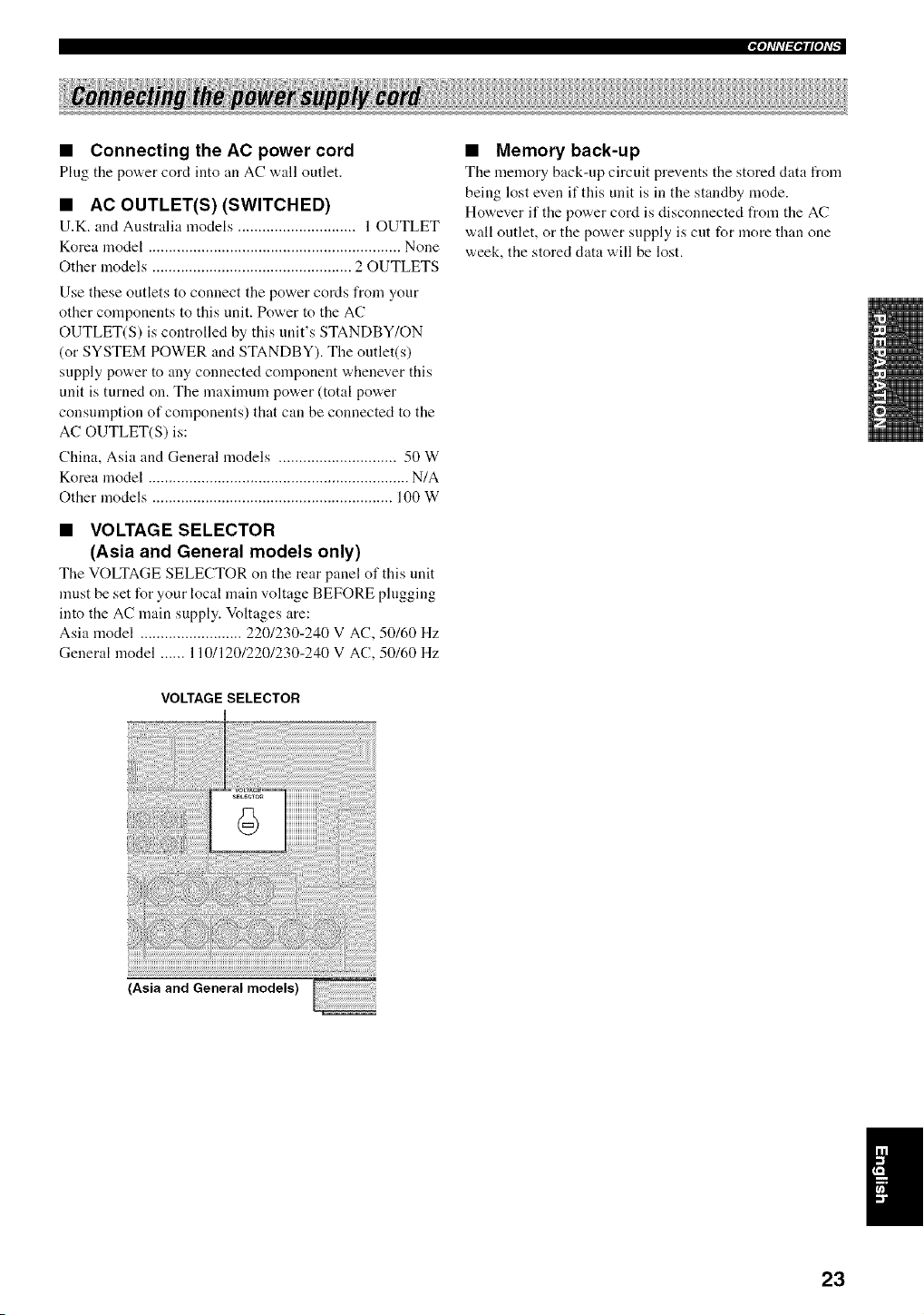
• VOLTAGE SELECTOR
(Asia and General models only)
TILe VOLTAGE SELECTOR on tile rear panel of this unit
must be set for your local main voltage BEFORE plugging
into the AC main supply. Voltages are:
Asia model ......................... 220/230-240 V AC, 50/60 Hz
General model ...... 110/120/220/230-240 V AC, 50/60 Hz
VOLTAGE SELECTOR
m
2;,;,;U ),,/;" a, ;2 ...... ...............
(Asiaand Generalmodels)
• Memory back-up
The memory back-up circuit prevents the stored data from
being lost even if this unit is in the standby mode.
However if the power cord is disconnected from the AC
wall outlet, or the power supply is cut for more than one
week, the stored data will be lost.
!1
23
II_Oh'hT_lliOh'_
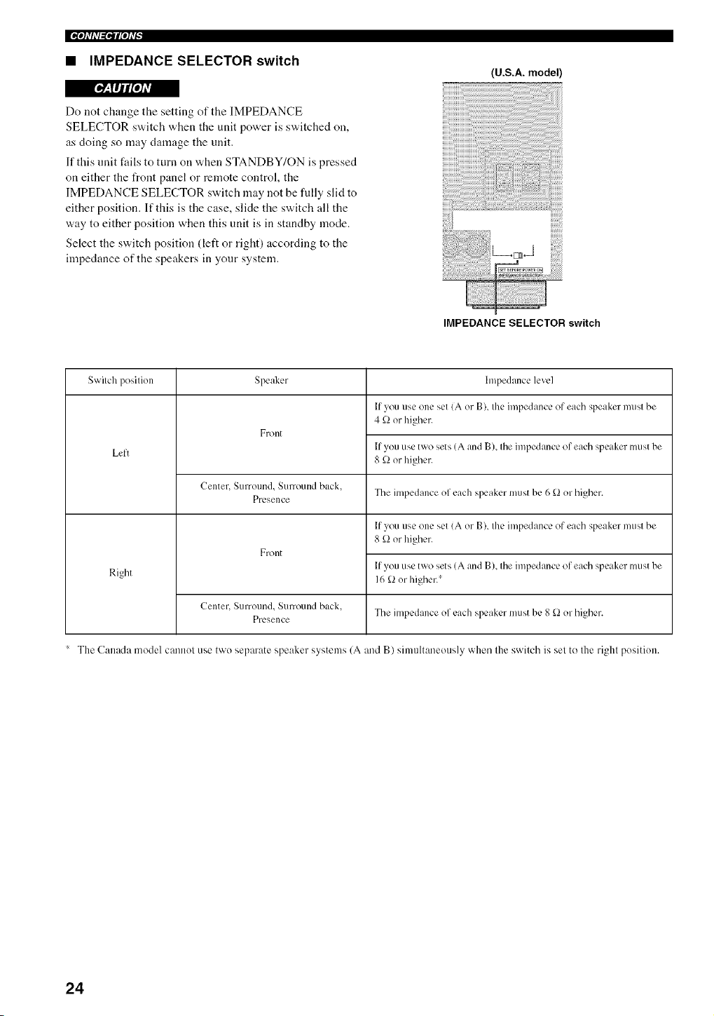
• IMPEDANCE SELECTOR switch
(U.S.A. model)
r_Y,MH[*] =vA
Do not change the setting of the IMPEDANCE
SELECTOR switch when the unit power is switched on,
as doing so may damage the unit.
If this unit fails to turn on when STANDBY/ON is pressed
on either the front panel or remote control, the
IMPEDANCE SELECTOR switch may not be fully slid to
either position. If this is the case, slide the switch all the
way to either position when this unit is in standby mode.
Select the switch position (left or right) according to the
impedance of the speakers in your system.
IMPEDANCE SELECTOR switch
Switch position Speaker
Front
Left
Center, Surround, Surround back,
The impedance of each speaker must be 6 £) or higher.
PrL, sence
Front
hnpedance level
If you use one set (A or B), the impedance of each speaker must be
4 k_ or higher.
If you use two sets (A and B), the impedance of each speaker must be
8 _ or higher.
If you use one set (A or B), the impedance of each speaker must be
8 _ or higher.
Right
Center, Surround, Surround back.
The impedance of each speaker must be 8 _ or higher.
Presence
The Canada model cannot use two separate speaker systems (A and B) simultaneously when the switch is set to the right position.
If you use two sets (A and B), the impedance of each speaker must be
16 _ or higher.*
24
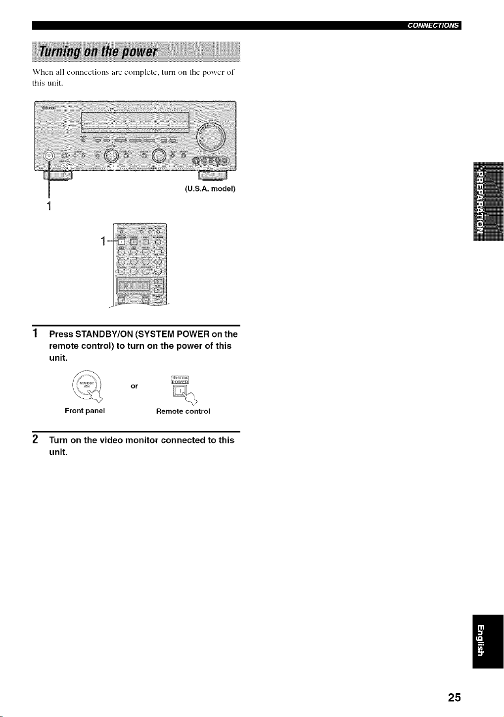
When all connections are complete, turn on the power of
this unit.
(U.S.A. model)
Press STANDBY/ON (SYSTEM POWER on the
remote control) to turn on the power of this
unit.
or
Front panel Remote control
Turn on the video monitor connected to this
unit.
25
This receiver employs YAMAHA Parametric Room
Acoustic Optimizer (YPAO) technology which lets you
avoid troublesome listening-based speaker setup and
achieves highly accurate sound adjustments. The supplied
optimizer microphone collects and analyzes the sound
your speakers produce in your actual listening
euvironnlent.
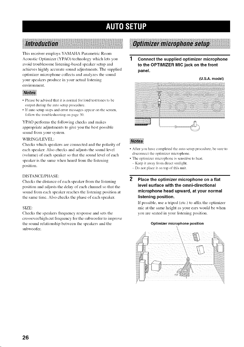
Connect the supplied optimizer microphone
to the OPTIMIZER MIC jack on the front
panel.
(U.S.A. model)
• Please be advised that it is normal for loud test tones to be
output during the auto setup procedure.
• If auto setup stops and error messages appear on the screen,
lk)llowthe troubleshooting on page 30.
YPAO performs the following checks and makes
appropriate adjustments to give you the best possible
sound from your system.
WlRING/LEVEL:
Checks which speakers are connected and the polarity of
each speaker. Also checks and adjusts the sound level
(volume) of each speaker so that the sound level of each
speaker is the same when heard from the listening
position.
DISTANCE/PHASE:
Checks the distance of each speaker from the listening
position and adjusts the delay of each channel so that the
sound from each speaker reaches the listening position at
the same time. Also checks the phase of each speaker.
SIZE:
Checks the speakers frequency response and sets the
crossover/high cut frequency for the subwoofer to improve
the sound relationship between the speakers and the
sl.lbwoofer.
• After you have completed the auto setup procedure, be sure to
disconnect the optimizer microphone.
• The optimizer microphone is sensitive to heat.
Keep it away trom direct sunlight.
Do not place it on top of this unit.
Place the optimizer microphone on a flat
level surface with the omni-directional
microphone head upward, at your normal
listening position.
If possible, use a tripod (etc.) to affix the optinfizer
mic at the same height as your ears would be when
you are seated in your listening position.
Optimizermicrophoneposition
\
26
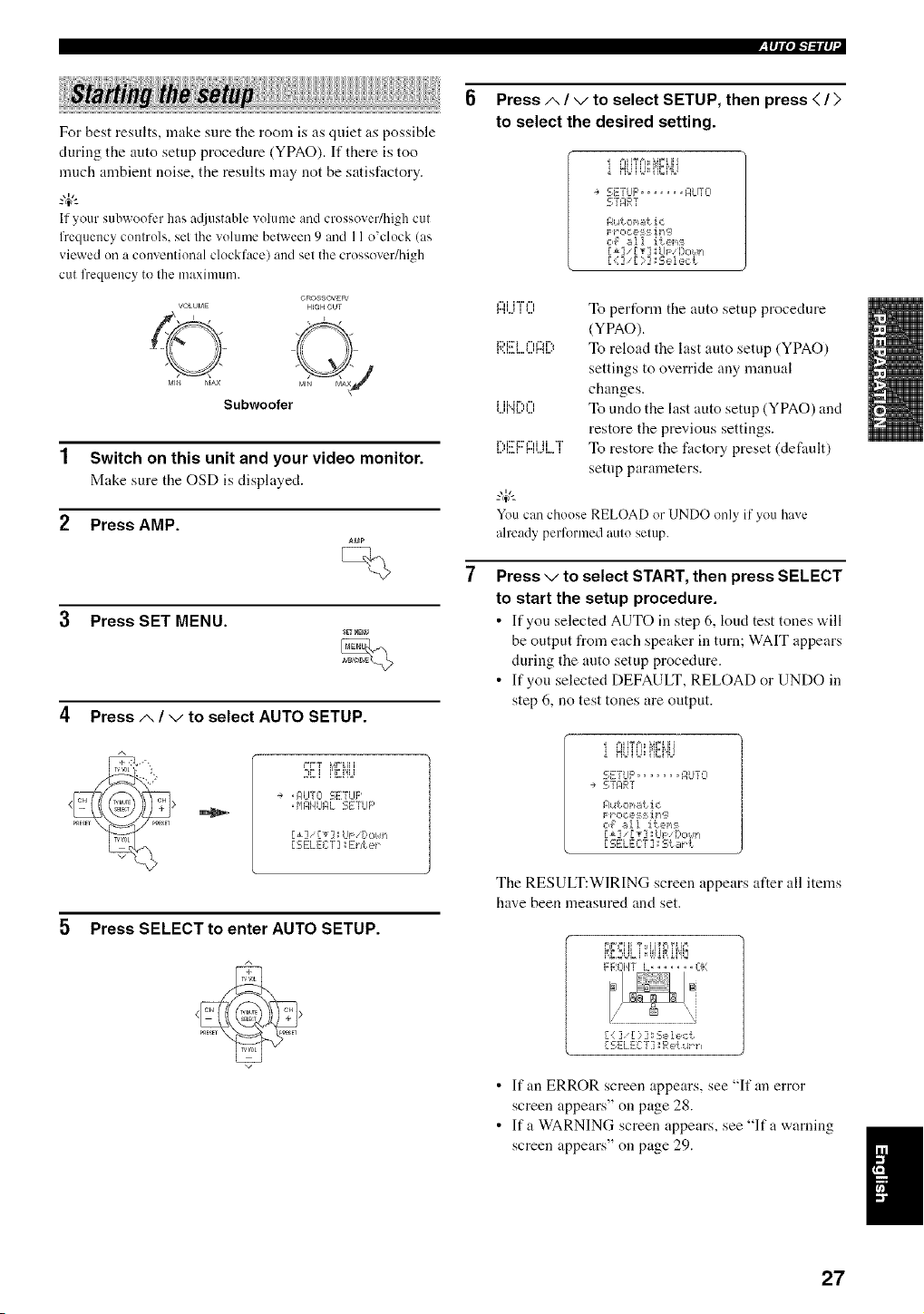
lql'lFl-"ilq
For best results, make sure the room is as quiet as possible
during the auto setup procedure (YPAO). If there is too
much ambient noise, the results may not be satisfactory.
If your subwooli:r has at[iustablevolume and crossover/high cut
frequency controls, set the volume belween 9 and 11o'clock (as
viewed oil a conventional clockface) and set the crossover/high
cut frequency to the nmximmn.
VOLUME
©
MI_ MAX
Subwoofer
OROSSOVER'
HIGH CUT
Switch on this unit and your video monitor.
Make sure the OSD is displayed.
Press AMP.
Press SET MENU.
4 Press/,, / v to select AUTO SETUP.
A
++"
+++_] r+3LP+Itl
..... ii_i% +
÷ +MI+JTCI I_;ETLIF'
+P'IMI4I.fI_L _+,t,'-E'r"m,
[1] [T];LIs: [:,o/,ir_
5 Press SELECT to enter AUTO SETUP.
Press/,, / v to select SETUP, then press < / >
to select the desired setting.
+==H%==++_V+IH
SETUP, ...... F,LITO
Nutonatic
c4 _,II ite+,_:_
[1] _[T] UF [)o/F/
[<] [ }] _s,_=l,_,ct
,...,,...+.......,+..., To perfonn the auto setup procedure
(YPAO).
.............. "+ To reload the last auto setup (YPAO)
1... k. i.. ,.., r...q..=<
settings to override any manual
changes.
+...,,+ii..+r'.,+",_,....+...,To undo the last auto setup (YPAO) and
restore the previous settings.
,....,...,r"i::r+::v"i,...,,...+,...+iT, To restore the factory preset (default)
setup parameters.
You can choose RELOAD or UNDO only if youhave
already performed auto setup.
Press v to select START, then press SELECT
to start the setup procedure.
• If you selected AUTO in step 6, kind test tones "a.ill
be output from each speaker in turn; WAIT appears
during the auto setup procedure.
• If you selected DEFAULT, RELOAD or UNDO in
step 6, no test tones are output.
+==H%==_+_VLIII
5ETLIFq ...... F,Ur 0
-+ 5TMR]
Aut o+,_tic
r_r o c e:_ :+i rl,;._
c,,_ _AI ite+_:_
[SELECT ] ;E;t_r t
The RESULT:WIRING screen appears after all items
have been measured and set.
M,M,2+O+, +,,'0_,0,,_
FROTH i_+ ...... ++1}
[i ]• [ ) ]: Se 1ect
[SELEC:'T] Fqe[+.4_r_
• If an ERROR screen appears, see "If an error
screen appears" on page 28.
• If a WARNING screen appears, see "If a warning
screen appears" on page 29.
27
IRlql",l"/"ll q
Use the cursor buttons to display the results.
• Press A / v to disphty int_nnation about
individual results.
• Press < / > to switch between each result list.
_IF+++I+ T tlTriYLh +,
F FqCII4]' L ....... +3}1
{ : ] [ ::,] _Sele,:t
[ SELECT] Retqth
9 When finished, press SELECT.
The RESULT:EXIT screen appears.
10 Press/', / v to select SET or CANCEL.
F:ESLLT E::+:ZT
NO i,JMRND4G
RESLIL[ LZST
. },SE:r C:I:]HCEL
Ill [_] _UF Dciun
[SELECT] sE_/t e_
,:::;i::r'i"
i..+,i",q 'i,...i.. i....
To apply the auto setup (YPAO)
settings.
To cancel the auto setup (YPAO)
withont making any changes.
11 Press SELECT to set or cancel the auto
setup settings.
_.,#._
If you are not satisfied with the result or want to manually adjust
each setup parameter, use the mauual setup parameters (see
page 52),
• If E-10 appears during testing, restart the prucedure from step 3.
• Tu cancel the 0_ulosetup prucedure belure cumplefion, press
SET MENU.
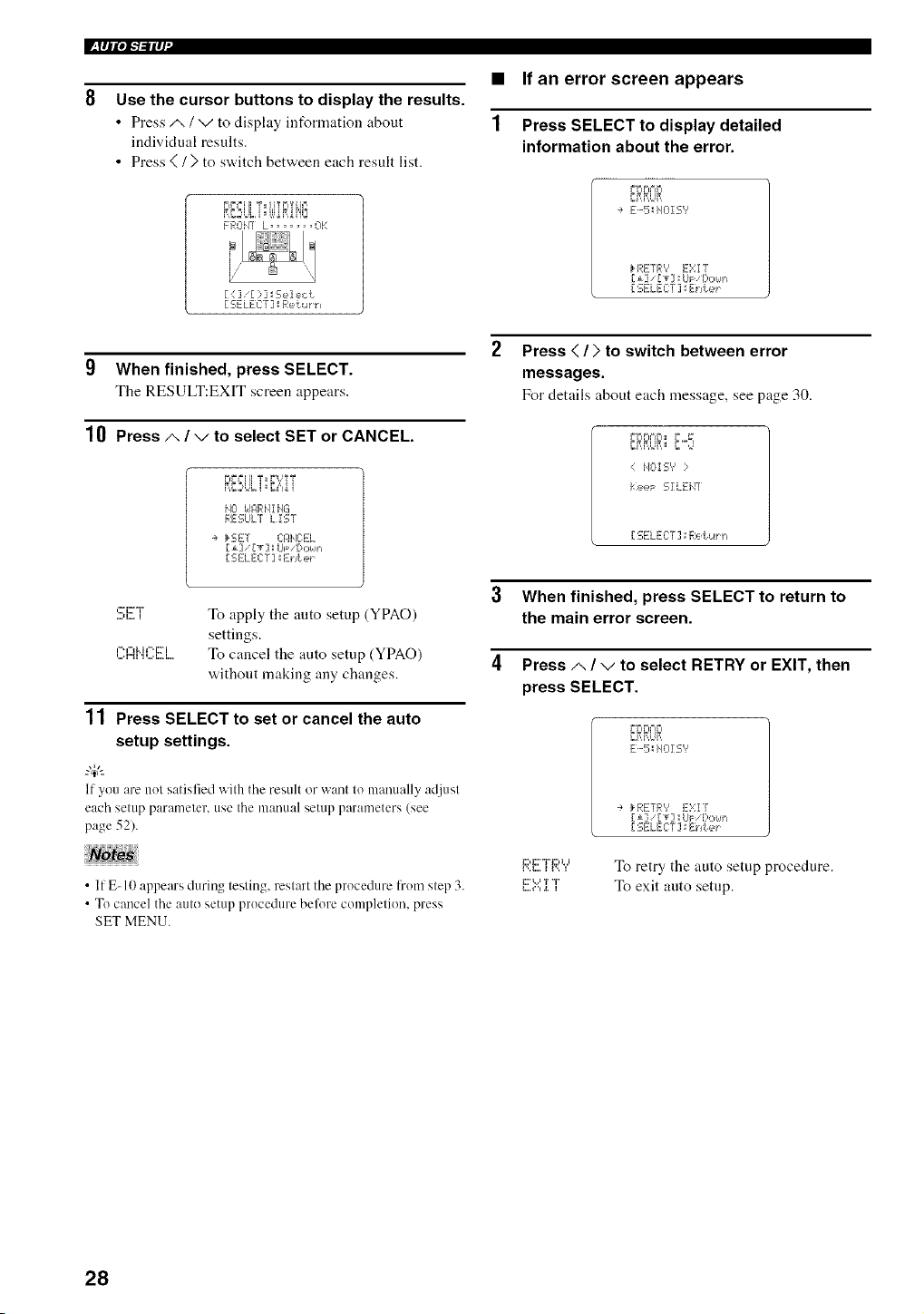
• If an error screen appears
1 Press SELECT to display detailed
information about the error.
YrIP.'IFI
÷ E-5_HOIS'?
_.REFR',' E:,:I ]
r i] r T] ; L/F I::,,:,/,,_+
[ SELECT ]',IE:hte_
Press < / > to switch between error
messages.
For details about each message, see page 30.
r+riPi+=iD+,+ ,_
_M,M,Ur,,+_'="
MOI S'? :
t:eeF SZLEil]'
-r. =-v ,,r.,.!, ....
3 When finished, press SELECT to return to
the main error screen.
4 Press/,, / v to select RETRY or EXIT, then
press SELECT.
YI=IrI='IFI
E-5 HOI S"
i:::,i:::'"ri:::,t.i
i',,i,,,, i i,,, i
i:::%,,=T <'i"
•÷ kRETR'? E:,:I /
[i] IT] ; UF [),:,_,lh
-r. r++T ,,- f ....
To retry the auto setup procedure.
To exit auto setup.
28
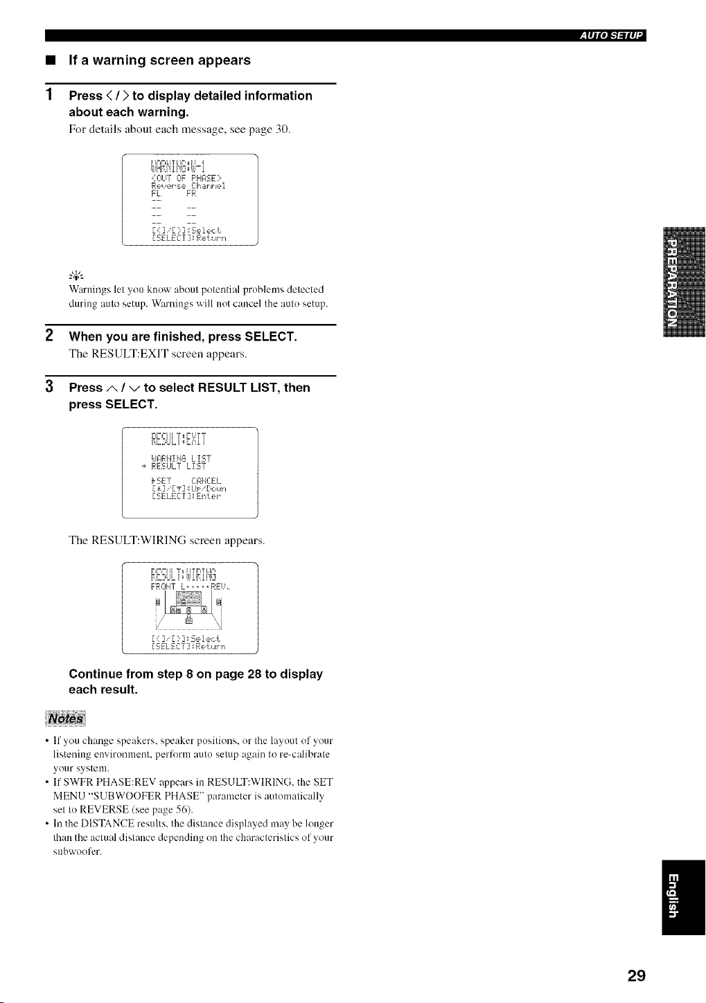
• If a warning screen appears
1 Press </) to display detailed information
about each warning.
For details about each message, see page 30.
lql'l"b'ilq
4OUT OF F'HI:ISE}
FL FR
[SELECT:] Ret+,lrh
Warnings let you know about potential problems detected
during auto setup. Warnings will not cancel the auto setup.
2 When you are finished, press SELECT.
The RESULT:EXIT screen appears.
3 Press A / v to select RESULT LIST, then
press SELECT.
v,+,+,+T;F',:Ti
_,D,:_UL,+,:':,o,
idJ:IRH!HB LIST
-÷ RESLILT LIST
_ SE:I CIqHC:EL
[ SELEC:T ] ',IEnLer
The RESULT:WIRING screen appears.
;'_':;iiiv ,_r,,+u,+,
,,_,,,++o,+,+. +M,o,,J
FROHT L ..... RFiL,
[ (: ] [ :::] ; Se i ec t
[SELECT] R'_li_I_PI
Continue from step 8 on page 28 to display
each result.
• If you change speakers, speaker positions, or the layout of your
listening environment, perlorm auto setup again to re-calibrate
your system.
• If SWFR PHASE:REV nppears in RESULT:WIRING. the SET
MENU "SUBWOOFER PHASE" parameter is automatically
set to REVERSE (see page 56).
• In the DISTANCE results, the distance displayed may be longer
than the actual distance depending on the characteristics of your
subwoofcr.
I
29
l'+tlllOi-'/_llq
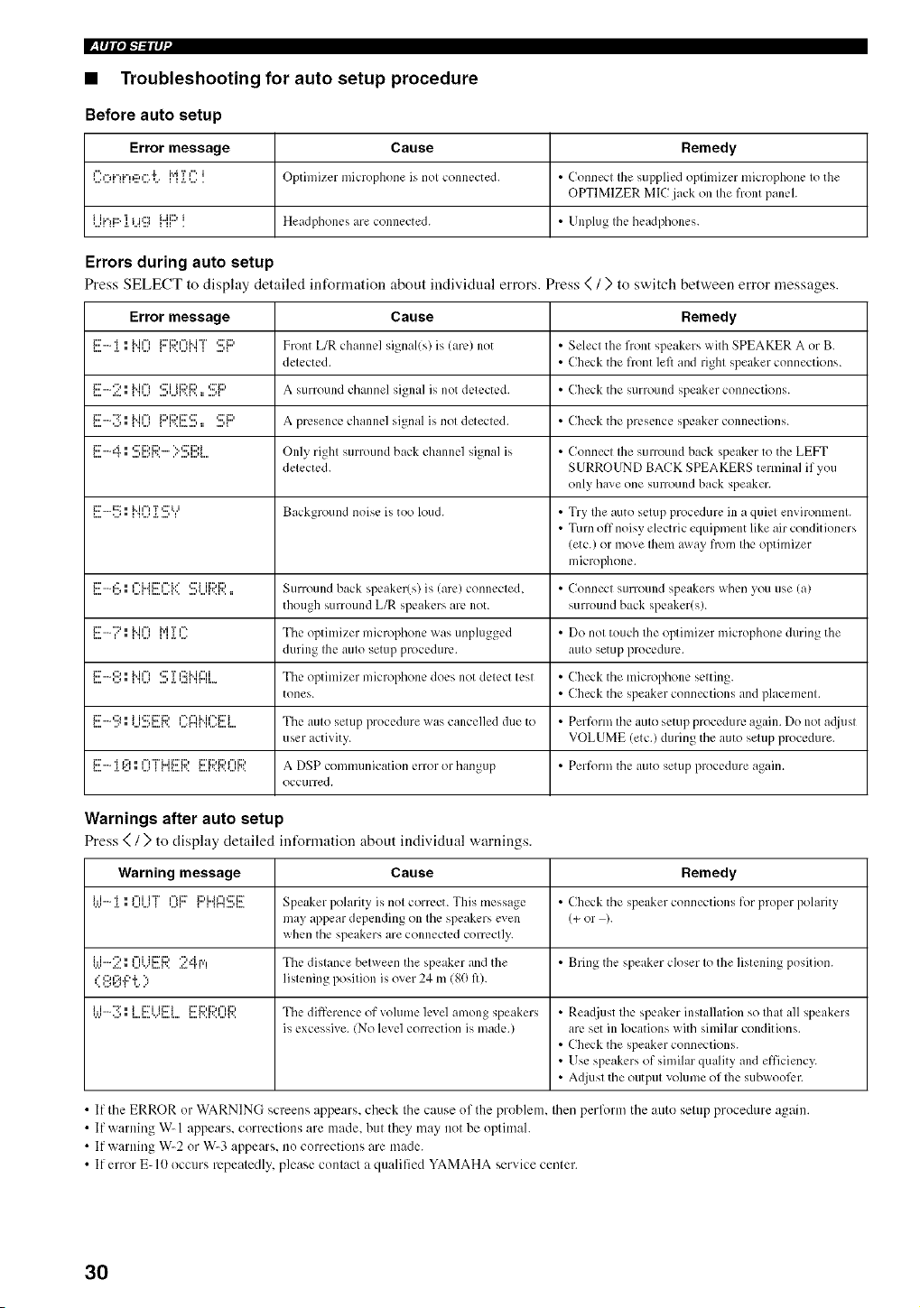
• Troubleshooting for auto setup procedure
Before auto setup
Error message Cause Remedy
I h=H."_i."_g:,r'iLfq {I : _ Optimizer microphone is nol connected+ • Connecl Ihe supplied oplilnizcr microphone Io the
OPTIMIZER MIC jack on Ihe front panel.
Ui'!F::"]. i...i'ii[I i"[[::'! Headphones are connected. • Unplug Ihe headl)hones.
Errors during auto setup
Press SELECT to display detailed infornmtion about individtml errors. Press < / ) to switch between error messages.
Error message Cause Remedy
l....i:::''".l+'i.,,, 1'l,..+_i"i¢"lli:::'i::)¢"lM"i"r.<,..+q'II <...,lC:'i:::' Front L/R channel signal(s) is (arc) not • Selecl the front speakers wilh SPEAKER A or B+
delected. • Check tile front left and right speaker connections.
l....i:::''""[_.=:.,," IMI%'I'..._....''...q ".I "._:::'i i i::M:::'_= ....q'::Ti:::' a SU rl"OUlld channel si_na]_ is not dl:ll:ctl:d. • Check tile SUFrOUlId speaker connections.
l,,,,i:::'":_=,,,._,,"l,l,,,._i"i¢=lli:::'i::)i::7_:::'r..i......., :, ...., _¢:' i:::, A prcsel]cC chanl]c] signal is nol detected. • Check tile presence speaker conllcClion S.
_....i:::''""i"r,," ....q...q'.._:::'i::)i::)......'"':::_i::M....q...q. OnlY, righl sunound back channel signal is • Connecl Ihe surround back speaker to the LEFT
delected. SURROUND BACK SPEAKERS terminal if you
only have one surround back speaker.
l....i:::''"i:::_..j"' H'.Ji"i¢=1._.T....'CI"II Background noise is too loud. • Try Ihe auto selup procedure ill a quicl envh-onmcnl.
• Turn off noisy electric equipment like air con(lit ioners
(etc.) or move Iheln away from file optimizer
microphone.
l....i:::''"':::'.J,," _....Ir '.i..d i:::"i". i...'n..,=_...._'......, ,...,r..l '.._:::'i i i::M:::, :: Surround back Slx.akcr(s) is (arc) connccled, • Connect surround speakers when you use (a)
though surround L/R speakers are not. surround back speaker(s).
_....i:::'"::'_,,H,...,"i..i,"_ _ _._.,....i"i'r ,'-. The optilnizer microphone was unplugged • Do nol touch Ihe oplinlizer microphone during the
duriJlg Ihe aulo sem l) procedure, aulo setup procedure.
1....i:::''"'D'.J"' li"i¢=I'P...'...'*:::'._.T'..,II¢:5M I"H'i r"H..... The optilllizer microl)hone does not delect lesl • Check the microl)hone seltinv.
tones. • Check tile speaker connections and placemenl.
l....i:::''"'::;l..=""' *...'....q..,A'..ii ,::7 i:7i1::, '...=r"l _¢"=r'l k i ¢"q:::'i.i ,...=_...._.. The aUIO setup procedure _-X,'as cancelled due to • Perform tile aLlIO setup procedure again. Do not adju sI
user activity. VOLUME (etc.) during the auto setup procedure.
_....i:::'a.'i*:..,_'::'.",...,f"l"FL.ii:::'i::)__ H....r.. _....r.._'..,...,r..ii::'i::M:::'r'H:::, A DSP conllllunication error or hangup • Perform tile atltO setup procedure again.
occtlrred.
Warnings after auto setup
Press ( / ) to display detailed int_rmation about individual warnings.
Warning message Cause Remedy
i.,.i-:[',',OUT Ii?i::r{:::'i"4'g::l:!!!:i!!ESpeaker polarity is nol com:ct. This message • Check tile speaker connections for proper polarity
may appear depending on Ihe speakers even (+ or ).
when tile speakers are connected correctly.
ijj-2 II 0i.)[!!i;?. 24fq The dislance belween the speaker and the • Bring tile speaker closer Io the listening position.
,.' ,:::,,:_.,::..i.'., li slenin _ lx)silion is over ?4 m (go fl).
•.. ,...,,:.., 1 ,....."
•.ui'i""";_=....,nn I....L..="."I....{....ii::riii2'i l....{".F'.t...H".i:::'i::)i:::'r'li::)Tile difference of vohlme level among speakers • Rea(ljust 1he speaker installation so Ihal all speakers
is excessive. !No level correction is made.) are set ill locations with similar conditions.
• Check the speaker connections.
• Use speakers of similar quality and efficiency,.
• Adjusl tile outpul volume of Ihe subwool_:r.
• If the ERROR or WARNING screens appears, check the cause of the problem, then perlk_rm the auto setup procedure again.
• If warning W- 1 appears, corrections are made. but they may not be optimal.
• If warning W-2 or W-3 appears, no corrections are made.
• If error E- I0 occurs repeatedly, please contact a qualified YAMAHA service center.
3O
(U.S.A. model)
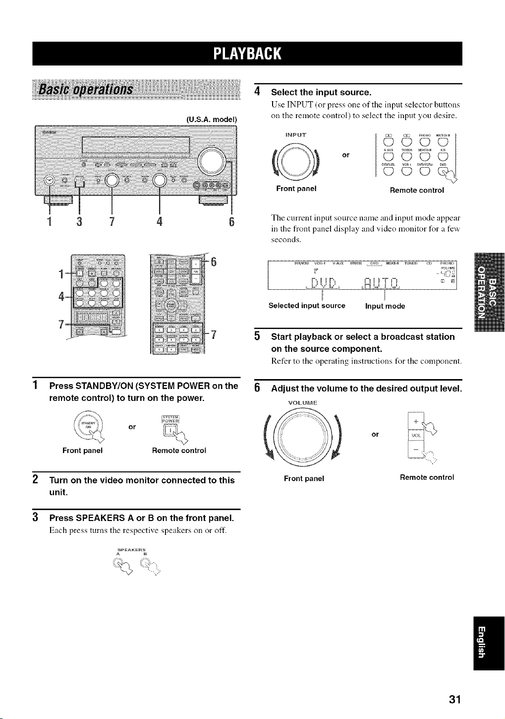
Select the input source.
Use INPUT (or press one of the input selector buttons
on the remote control) to select the input you desire.
iNPUT
Front panel
or
© U
© °U
Remote control
7
The current input source name and input mode appear
in the front panel display and video monitor for a few'
seconds.
Dv_/_2 vcR 1 v Aux DW,CBL DVD _D,_¢_ TUNER C_ PHONO
VOWME
i"_i i i"_ £_i i'g"i"i -_,
Selected input source Input mode
Press STANDBY/ON (SYSTEM POWER on the
remote control) to turn on the power.
_iSYSTEr_
or
Frontpanel Remotecontrol
2 Turn on the video monitor connected to this
unit.
3 Press SPEAKERS A or B on the front panel.
Each press turns the respective speakers on or oft'.
,_PEAKE_
Start playback or select a broadcast station
on the source component.
Refer to the operating instructions for the component.
Adjust the volume to the desired output level.
VOLUME
o
Frontpanel Remotecontrol
31
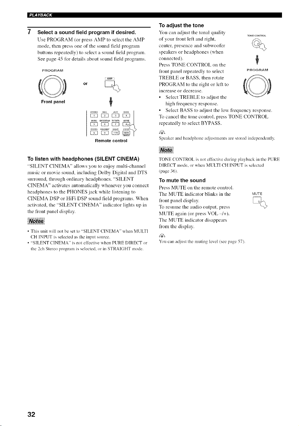
Select a sound field program if desired.
Use PROGRAM (or press AMP to select the AMP
mode, then press one of tile sound fiekt program
buttons repeatedly) to select a sound fiekt program.
See page 45 for details about sound field programs.
P_OGRAM
or
Front panel
*TEaEO HALL _ZZ
_ _ _i__aUSI_ERTERTAJ_WTHTR _aOWE
U_DTS PUn_DI_E_r_m
Remote control
To adjust the tone
You can adjust tile tonal quality TONECONTROL
of your front left and right,
center, presence and subwoofer
speakers or headphones (when
connected). ¢
Press TONE CONTROL on the
front panel repeatedly to select PF_OGF_AM
TREBLE or BASS, then rotate
PROGRAM to the right or left to
increase or decrease.
• Select TREBLE to ac[iust the
high frequency response.
• Select BASS to adjust the low frequency response.
To cancel the tone control, press TONE CONTROL
repeatedly to select BYPASS.
Speaker and headphone a([iustments are stored independently.
To listen with headphones (SILENT CINEMA)
"SILENT CINEMA" allows you to enjoy nndti-channel
nmsic or movie sound, including Dolby Digital and DTS
surround, through ordinary headphones. "SILENT
CINEMA" activates automatically whenever you connect
headphones to the PHONES jack while listening to
CINEMA DSP or HiFi DSP sound field programs. When
activated, the "SILENT CINEMA" indicator lights up in
the front panel display.
• This unit will not be set to "SILENT CINEMA" when MULTl
CH INPUT is selected as the input source.
• "SILENT CINEMA" is not elti_ctive when PURE DIRECT or
the 2ch Stereo program is selected, or in STRAIGHT mode.
TONE CONTROL is not efl)ctive during playback in the PURE
DIRECT mode, or when MULTI CH INPUT is selected
(page 36).
To mute the sound
Press MUTE on the remote control.
The MUTE indicator blinks in the MUTE
front panel display.
To resume the audio output, press
MUTE again (or press VOL W+).
The MUTE indicator disappears
from the display.
You can a¢{iust the muting level (see page 57).
32
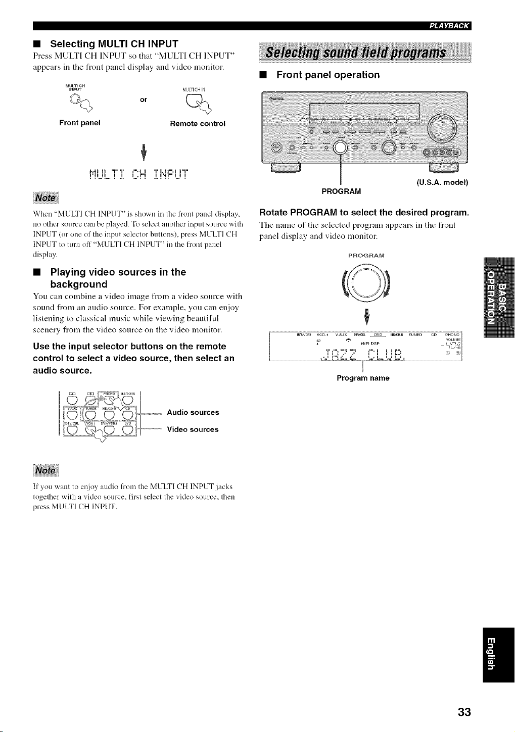
• Selecting MULTI CH INPUT
Press MULTI CH INPUT so that "MULTI CH INPUT"
appears in the front panel display and video monitor.
MULT_CH
)NpU"r
%
Front panel
or
MULFICH IN
Remote control
I'H H I I I .l"l I _"H" I I I
• Front panel operation
PROGRAM
{U.S.A. model)
When "MULTI CH INPUT" is shown in the front panel display,
no other source can be played. To select another input source with
INPUT (or one of the input selector buttons), press MULTI CH
INPUT to turn ofl "MULTI CH INPUT" in the front panel
display.
• Playing video sources in the
background
You can combine a video image from a video source with
sound from an audio source. For example, yon can enjoy
listening to classical nmsic while viewing beautiful
scenery from the video source on the video monitor.
Use the input selector buttons on the remote
control to select a video source, then select an
audio source.
Rotate PROGRAM to select the desired program.
The name of the selected program appears in the front
panel display and video monitor.
PROGRAM
x PHONO
DTV,e_LHI_}DSpDVD )eD,eDR rUNeg CD {gVOLU_aE{_]
DW,W:_* VCRp1 V _U
* Uq C
TCi'7 7' i'i i i i::!!
Program name
Audio sources
.......................Video sources
If you want to ei!joy audio from the MULTI CH INPUT jacks
together with a video source, first select the video source, then
press MULTI CH INPUT.
33
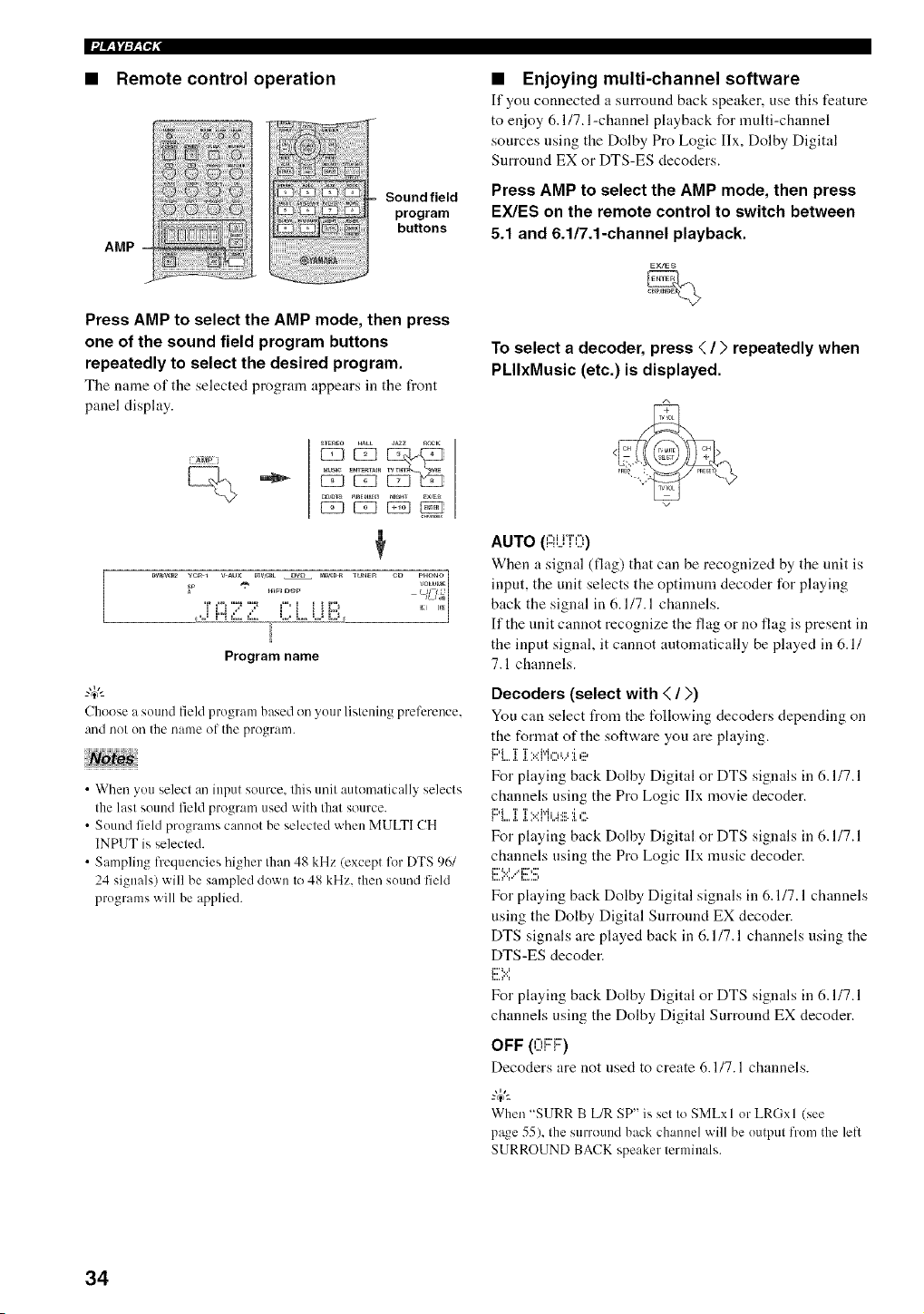
• Remote control operation
AMP
Sound field
program
buttons
Press AMP to select the AMP mode, then press
one of the sound field program buttons
repeatedly to select the desired program.
Tile name of tile selected progrmn appears ill tile front
panel display.
• Enjoying multi-channel software
If you connected a surround back speaker, use this feature
to enjoy 6.117. l-channel playback for multi-channel
sources using the Dolby Pro Logic Ilx, Dolby Digital
Surround EX or DTS-ES decoders.
Press AMP to select the AMP mode, then press
EX/ES on the remote control to switch between
5.1 and 6.1/7.1-channel playback.
To select a decoder, press < / ) repeatedly when
PLIIxMusic (etc.) is displayed.
{g_P i
¢
I_TR_F,2 1 PHONO
VC'a _ mFI D_XP VOWME
Program name
Choose a sound field program based on your listening preference.
and nol on the name ()J-the progranl.
• When you select an input source, this unit autonmtically selects
the last sound field program used with that source.
• Sound field programs cannot be selected when MULTI CH
INPUT is selected.
• Sampling frequencies higher than 48 kHz (except liar DTS 96/
24 signals) will be sampled down to 48 kHz. then sound field
programs will be applied.
AUTO ({::ii..j{O)
When a signal (flag) that can be recognized by the unit is
input, the unit selects the optimum decoder for playing
back the signal in 6.1/7.1 channels.
If the unit cannot recognize the flag or no flag is present in
the input signal, it cannot automatically be played in 6.1/
7.1 channels.
Decoders (select with < / >)
You can select from the following decoders depending on
the format of the software you are playing.
i L.._. 2............
For playing back Dolby Digital or DTS signals in 6.1/7.1
channels using the Pro Logic IIx movie decoder.
I"'L...[.[?.::P'ff.42_.1.c;
For playing back Dolby Digital or DTS signals in 6.1/7.1
channels using the Pro Logic IIx music decoder.
L..._''r' L,-..,
For playing back Dolby Digital signals in 6.1/7.1 channels
using the Dolby Digital Surround EX decoder.
DTS signals are played back in 6.1/7.1 channels using the
DTS-ES decoder.
i:::''.:.:'.
For playing back Dolby Digital or DTS signals in 6.1/7.1
channels using the Dolby Digital Surronnd EX decoder.
OFF (0F::I:::')
Decoders are not used to create 6.1/7.1 channels.
When "SURR B L/R SP" is set to SMLxl or LRGxl (see
page 55), the surround back channel will be output from the left
SURROUND BACK speaker terminals.
34
• Some 6. l-channel compatible discs do not have a signal (flag)
which this unil can automatically detect. When playing Ihese
kinds of discs with 6. l-channeL select a decoder (PLllx Movie.
PLllx Music. EX/ES or EX) manually.
• 6. l-channel playback is nol possible even i l EX/ES is pressed in
Ihe lollowing cases:
When "SURR L/R SP" (see page 54) or "SURR B L/R SP"
(see page 55) is set to NONE.
When the source connected to Ihe MULTI CH INPUT jack is
being played.
When the source being played does not contain surround left
and right channel signals.
When a Dolby Digital KARAOKE source is being played.
When "2ch Slereo ' or PURE DIRECT is selected.
• When the power of Ihis unil is turned off, Ihe inpul mode will be
reset to AUTO.
• When Ihe DTS-ES decoder is applied to DTS 96/24 signals, you
cannot use Ihe DTS 96124 decoding feature.
• The Pro Logic IIx decoder is not available when "SURR B L/R
SP" is set Io NONE (see page 55).
• PLllxMovie cannot be selecled when "SURR B L/R SP" is set
Io SMLxl or LRGxl (see page 55).
• Enjoying 2-channel software
Signals input from 2-channel sources can also be played
back on nmltiple channels.
Press rYI/DTS on the remote control to select the
decoder.
You can select from the tUllowing decoders depending on
the type of software you are playing and your personal
preference.
Standard processing for Dolby Surround sources.
CINEMA DSP enhanced processing for Dolby Surround
sources.
F::'F;;:OLO(!!iiC iT':.:' M,:::,_..,:i.e*
Dolby Pro Logic II/Ilx processing for movie software.
F::i:;;:OLO(!!iiC ir:.= i"i_...,._ii.:i.,:::.*
Dolby Pro Logic I]/llx processing t_r music software.
i::)i::)l", i ,"II':::T, '=` TT.. f::L:::,r,',,::a*
•. .................. • .. .. .............
Dolby Pro Logic II/IIx processing for game software.
[:,F:!!!;i{e,:::,:',6 r:i v,,:::,,,.,::_
DTS processing for movie software.
[)"F:!!!; i"{III_Cl :', l:,!!, lid,
a{::l
"i I11"
DTS processing for music software.
' Use the PLII/PLIIx parameter to select the Pro Logic I1 or Pro
Logic IIx decoders (see page 78).
The Pro Logic Ilx decoder is not available when "SURR B L/R
SP" is set Io NONE (see page 55).
35
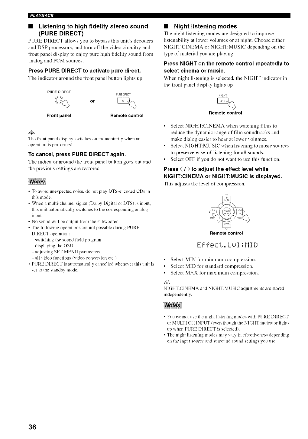
|i/_ll:_N,"
• Listening to high fidelity stereo sound
(PURE DIRECT)
PURE DIRECT allo,a,s you to bypass this unit's decoders
and DSP processors, and turn oft" the video circuitry and
front panel display to enjoy pure high fidelity sound from
analog and PCM sources.
Press PURE DIRECT to activate pure direct.
Tile indicator around tile front panel button lights up.
PORE DIRECT
PURE DIRECT
or
Front panel Remote control
The front panel display switches on momentarily when an
operation is performed.
To cancel, press PURE DIRECT again.
Tile indicator around the front panel button goes out and
the previous settings are restored.
• To avoid unexpected noise, do not play DTS-encoded CDs in
this mode.
• When a multi-channel signal (Dolby Digital or DTS) is input,
this unit automatically switches to the corresponding analog
input.
• No sound will be output from the subwoolcr.
• The li_llowing operations are not possible during PURE
DIRECT operation:
switching the sound field program
displaying the OSD
adjusting SET MENU parameters
all video fimctions (video conversion etc.)
• PURE DIRECT is automatically cancelled whenever this unit is
set to the standby mode.
• Night listening modes
The night listening modes are designed to improve
listenability at lower volumes or at night. Choose either
NIGHT:CINEMA or NIGHT:MUSIC depending on the
type of material you are playing.
Press NIGHT on the remote control repeatedly to
select cinema or music.
When night listening is selected, tile NIGHT indicator ill
the front panel display lights up.
NIGHT
Remote control
• Select NIGHT:CINEMA when watching fihns to
reduce the dynamic range of fihn soundtracks and
make dialog easier to hear at lower vohnnes.
• Select NIGHT:MUSIC when listening to music sources
to preserve ease-of-listening for all sounds.
• Select OFF if you do not want to use this flmction.
Press ( / > to adjust the effect level while
NIGHT:CINEMA or NIGHT:MUSIC is displayed.
This adjusts tile level of ccnnpression.
Remote control
i"'i",l", ...... i, i , ,'i ii ivlT i",,
t,,, ,r, ,r, u,,J t i i t ii ,,i,lltl
i,,,, i i ,,,, ,,,,, ,,,, ii i,,,, ,,, ,i, ,, i i ,i, i,,,
• Select MIN f_r minimum compression.
• Select MID for standard compression.
• Select MAX for maximum compression.
NIGHT:CINEMA and NIGHT:M13SIC a@lstments are stored
indepeudently.
• You canuot use the night listening modes with PURE DIRECT
or MULTI CH INPUT (even though the NIGHT indicator lights
up when PURE DIRECT is selected).
• The night listening modes may vary in elt'cctiveness depending
on the input source and surround sound settings you use.
36
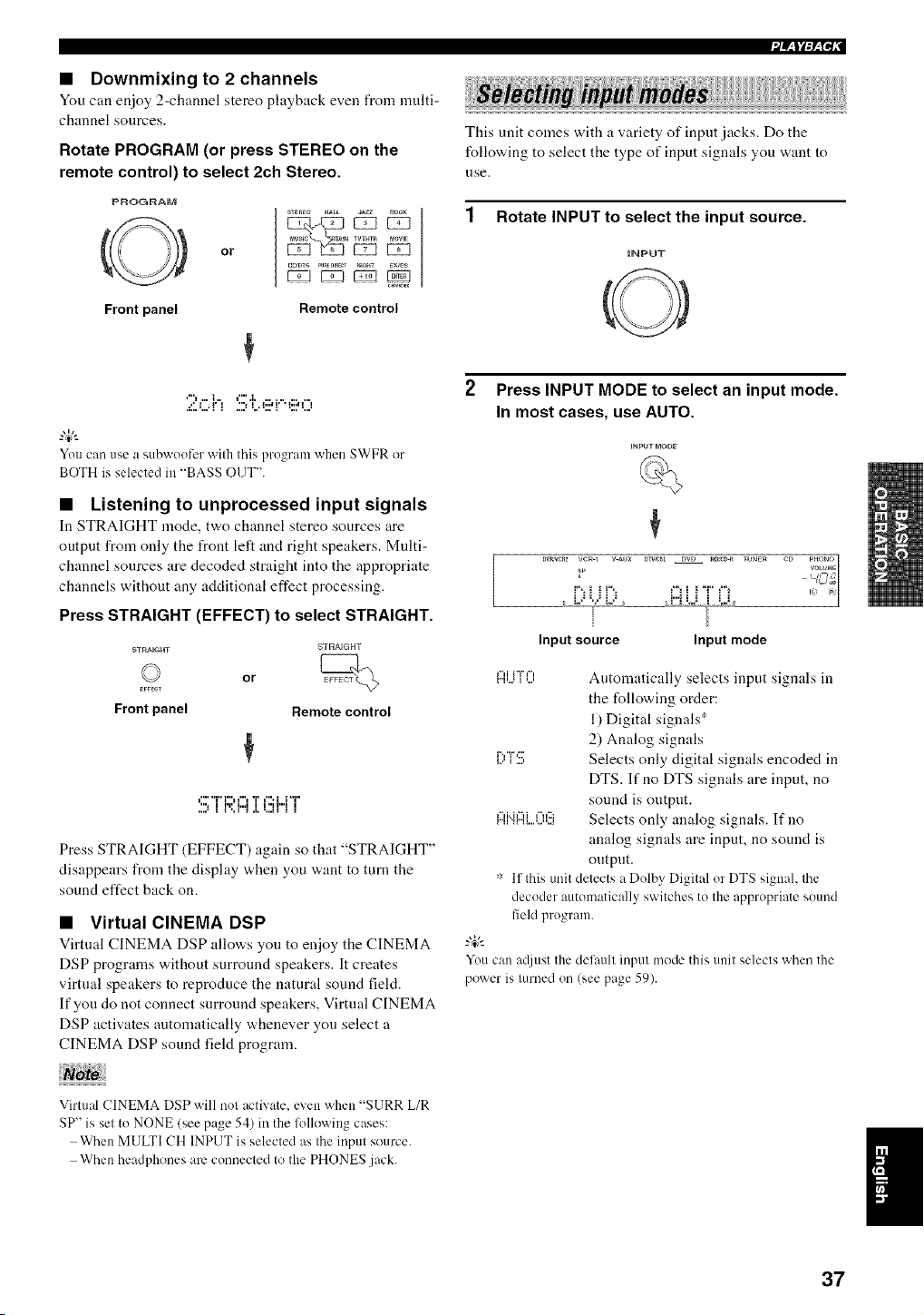
• Downmixing to 2 channels
Yuu can enjoy 2-channel stereo playback even fronl nmlti-
chau[lel sources.
Rotate PROGRAM (or press STEREO on the
remote control) to select 2ch Stereo.
PROGRAM
Front panel
or
_TEnEO HAL JAZZ _CK
C_DTS PUn_DJ_E__GHT EXmS
Remote control
You can use a subwootcr wifll this progranl when SWFR or
BOTH is selected in "BASS OUT".
• Listening to unprocessed input signals
In STRAIGHT mode, t'a.o channel stereo sources are
output from only the front left and right speakers. Multi-
channel sources are decoded straight into the appropriate
channels without any additional effect processing.
Press STRAIGHT (EFFECT) to select STRAIGHT.
STRAIGHT
or
E_FECT
Front panel Remote control
t"'"i"i"H"lTl",ii'T'
".lf'Ph,,llr'H"ll
Press STRAIGHT (EFFECT) again so that "STRAIGHT"
disappears from the display when you want to turn the
sound effect back on.
• Virtual CINEMA DSP
Virtual CINEMA DSP allows you to enjoy the CINEMA
DSP programs without surround speakers. It creates
virtual speakers to reproduce the natural sound field.
If you do not connect surround speakers, Virtual CINEMA
DSP activates automatically whenever you select a
CINEMA DSP sound field program.
Virtual CINEMA DSP will not activate, even when "SURR L/R
SP" is set to NONE (see page 54) in the lollowing cases:
When MULTI CH INPUT is selected as the input source.
When headphones are connected to the PHONES jack.
This unit comes with a variety of input jacks. Do the
fullowing to select the type of input signals you want to
use,
1 Rotate INPUT to select the input source.
iNPUT
2 Press INPUT MODE to select an input mode.
In most cases, use AUTO.
sP VOLU_E
i"_ii ih r3i ii 7_
r
Input source Input mode
,,,.,.......,,, Automatically selects input signals in
the following order:
1) Digital signals ;_
2) Analog signals
_r,v,:::,., Selects only digital signals encoded in
DTS. If no DTS signals are input, no
sound is output.
_...,""i"_r"_...,....,...,,..._r'":::Selects only analog signals. If no
analog signals are input, no sound is
output.
':: If this unit detects a Dolby Digital or DTS signah the
decoder automatically switches to the appropriate sound
field program.
-4¢-
YOu can at[iust the delaull inpul mode this unit selects when the
power is mined on (see page 59).
37
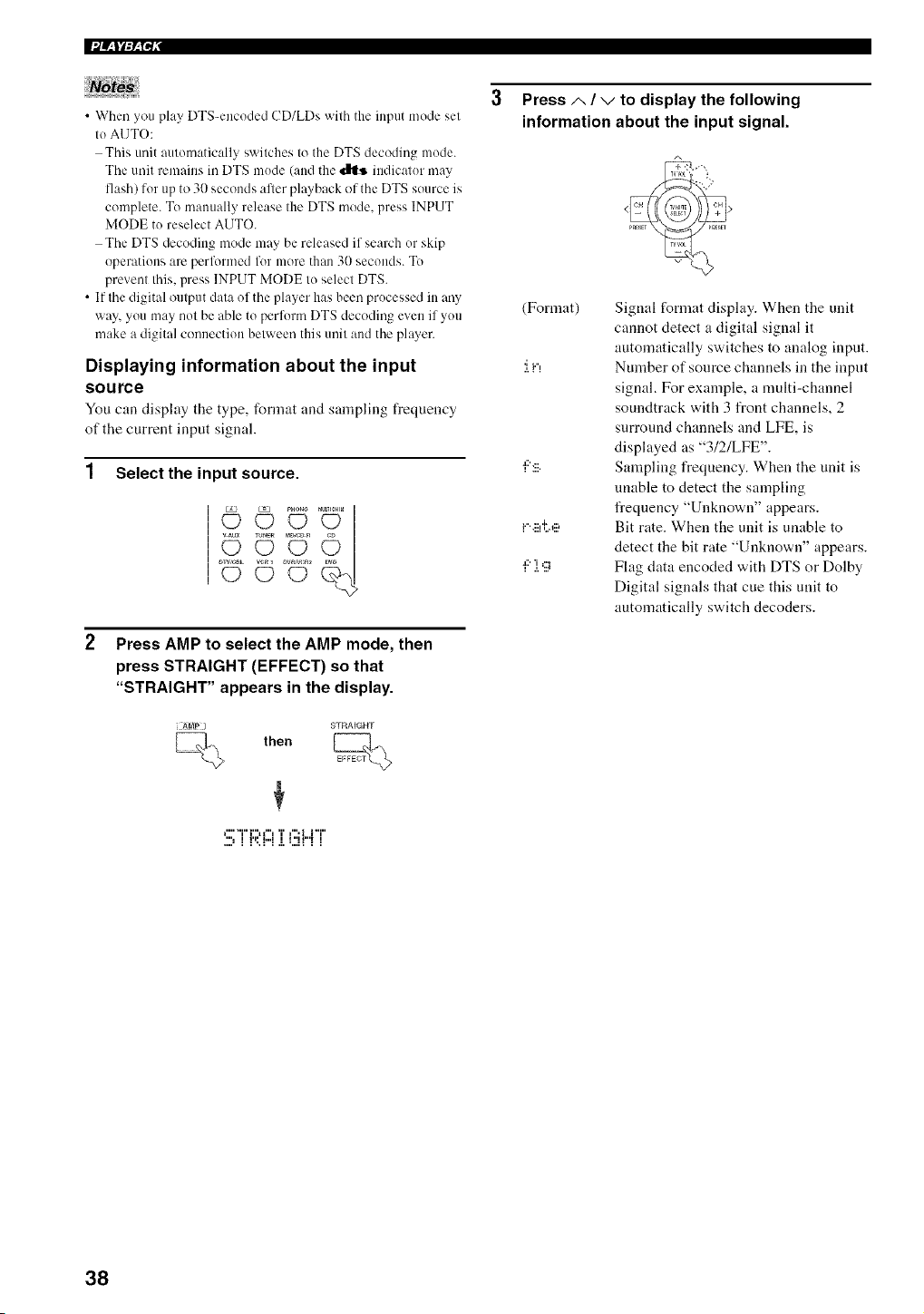
• When you play DTS-encoded CD/LDs with the input mode set
to AUTO:
This unit automatically switches to the DTS decoding mode.
The unit remains in DTS mode (and the _ indicator may
flash) for up to 30 seconds afler playback of the DTS source is
complete. To manually release the DTS mode, press INPUT
MODE to reselect AUTO.
The DTS decoding mode may be released if search or skip
operations are perfl_rmed fl)r more than 31)seconds. To
prevent this, press INPUT MODE to select DTS.
• If the digital output data of the player has been processed in any
way, you may not be able to perform DTS decoding even if you
make a digital connection between this unit and the player.
Displaying information about the input
source
You can display the type, format and sampling frequency
of the current input signal.
1 Select the input source.
_DJ_DR
Press AMP to select the AMP mode, then
press STRAIGHT (EFFECT) so that
"STRAIGHT" appears in the display.
) STRAIGHT
then
3 Press A / V to display the following
information about the input signal.
(Format)
'I i"l
a::' ...
i"'.:::l'l'.g:,
i::'].9
Signal format display. When the unit
cannot detect a digital signal it
automatically switches to analog input.
Number of source channels in the input
signal. For example, a multi-channel
soundtrack with 3 front channels, 2
surround channels and LFE, is
displayed as "3/2/LFE".
Sampling frequency. When the unit is
unable to detect the sampling
frequency "Unknown" appears.
Bit rate. When the unit is unable to
detect the bit rate "Unknown" appears.
Flag data encoded with DTS or Dolby
Digital signals that cue this unit to
automatically switch decoders.
_"'"I"I"H"_ T r".i i"i"
,,,a i I,p h,d I I ,,i pH I I
38
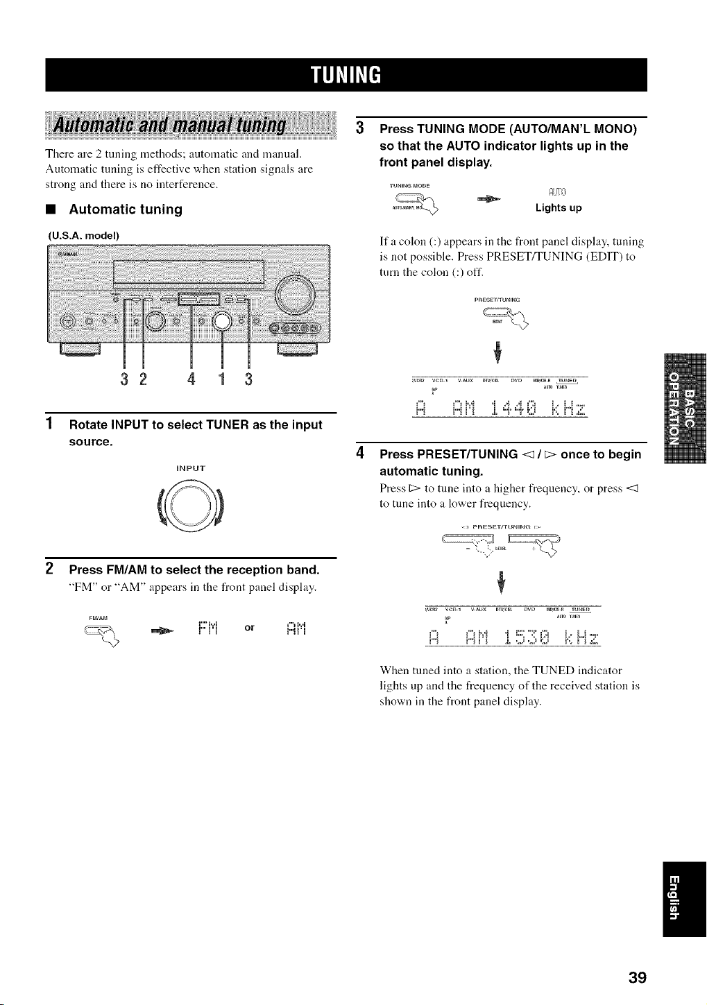
There are 2 tuning methods; automatic and manual.
Automatic tuning is effective when station signals are
strong and there is no iuterference.
• Automatic tuning
(U.S.A. model)
32 4 1 3
1 Rotate INPUT to select TUNER as the input
source.
iNPUT
Press TUNING MODE (AUTO/MAN'L MONO)
so that the AUTO indicator lights up in the
front panel display.
AIITO
Lights up
Ifa colon (:) appears in the front panel display, tuning
is not possible. Press PRESET/TUNING (EDIT) to
turn the colon (:) off.
_a/_2 vcR 1 v _u× _iv,_t DVD t_DS_DR TUNE_
_P
i:i ..............
Press PRESET/TUNING <1 / c> once to begin
automatic tuning.
Press C> to tune into a higher frequency, or press <1
to tune into a lower frequency.
Press FM/AM to select the reception band.
"FM" or "AM" appears in the front panel display.
i"" i...i f"t l...i
:"' ::'" or ::::""'.,
_W_2 VCR 1 V _UX DIV,_t DVD t_D,_DR TUNE_
_P
When tuned into a station, the TUNED indicator
lights up and the frequency of the received station is
shown in the front panel display.
1
39
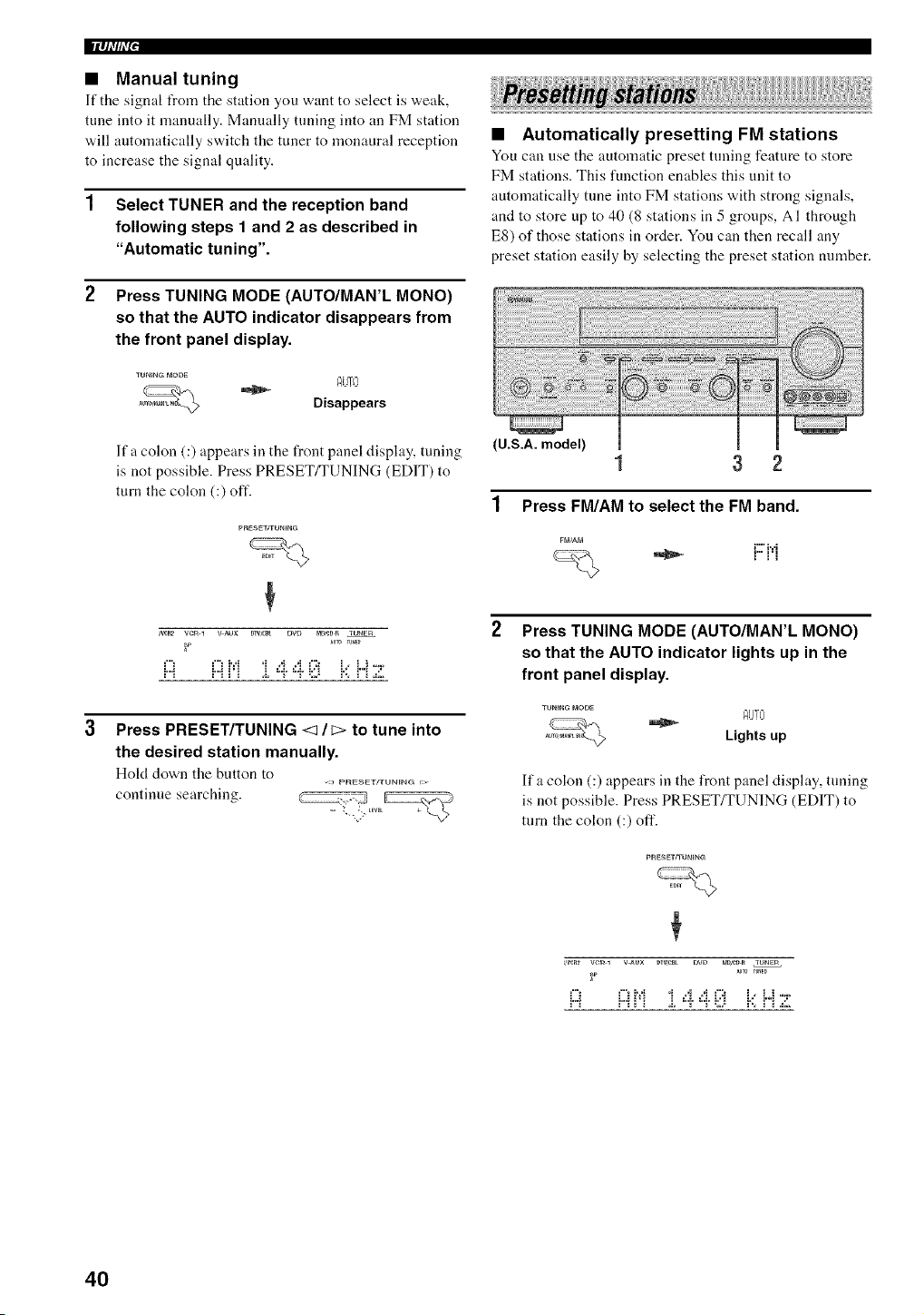
llqi'#ff
• Manual tuning
If tile signal IYomtile station you want to select is vveak,
tune into it manually. Manually tuning into an FM station
will automatically switch the tuner to monaural reception
to increase the signal quality.
1 Select TUNER and the reception band
following steps 1 and 2 as described in
"Automatic tuning".
2 Press TUNING MODE (AUTO/MAN'L MONO)
so that the AUTO indicator disappears from
the front panel display.
AiJTL+'
Disappears
lfa colon (:) appears in the front panel display, tuning
is not possible. Press PRESET/TUNING (EDIT) to
turn the colon (:) oft'.
pnESET]TUNIN_
+
_ veto i v Aux my,era twt_ mD,¢D_ TUNSR
_U_ rUlED
¢"+b'+ .+ .,i +4 +":+ i++i,+ .....
A +"11'+ +++"'++"'+++::+++'.+r'+.,::+
Press PRESET/TUNING <1 / c> to tune into
the desired station manually.
Hold down the button to
,) pFIE_ETFFUN_NG r:_
continue searching.
• Automatically presetting FM stations
You can use the automatic preset tuning feature to store
FM stations. This function enables this unit to
automatically tune into FM stations with strong signals,
and to store up to 40 (8 stations in 5 groups, AI through
E8) of those stations in order. You can then recall any
preset station easily by selecting the preset station number.
(U.S.A. model)
1 3 2
1 Press FM/AM to select the FM band.
i"" i,,,i
Press TUNING MODE (AUTO/MAN'L MONO)
so that the AUTO indicator lights up in the
front panel display.
Ifa colon (:) appears in the front panel display, tuning
is not possible. Press PRESET/TUNING (EDIT) to
turn the colon (:) off.
tmR_ veto 1 v _ux D+W_ DVD mD,eDR IUNSm
F
i:) .....................I:::1Mi 4 4, I:::1 i.:+H 7
40
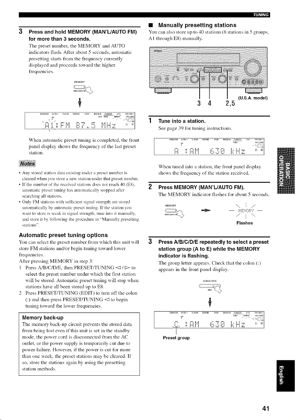
Press and hold MEMORY (MAN'L/AUTO FM)
for more than 3 seconds.
Tile preset number, tile MEMORY mM AUTO
indicators flash. After about 5 seconds, automatic
presetting starts t_om the frequency currently
displayed and proceeds toward the higher
frequencies.
DW_CR2 Ve_ * V_UX DIW_L DVD _D_D_ lUNE_ CD PHO_
SP _U_0 rUHF. "_MOR_' VOLU_aE1
___ = , ,., = ....................
When automatic preset tuning is completed, the front
panel display shows the frequency of the last preset
station.
• Any stored station data existing under a preset number is
cleared when you store a new station under that preset number.
• If the immber of the received stations does not reach 40 (E8),
automatic preset tuning has automatically stopped after
searching all stations.
• Only FM stations with sulticient signal strength are stored
automatically by autonmtic preset tuning. If the station you
want to store is weak in signal strength, tune into it manually,
and store it by following the procedure in "Manually presetting
stations".
Automatic preset tuning options
You can select the presetnmnber from which this unit will
store FM stations and/or begin tuning toward low,er
frequencies.
Alter pressing MEMORY in step 3:
1 Press A/B/C/D/E, then PRESET/TUNING <1 / C:>to
select the preset number under which the first station
will be stored. Automatic preset tuning will stop when
stations have all been stored up to ES.
2 Press PRESET/TUNING (EDIT) to turn off the colon
(:) and then press PRESET/TUNING <1 to begin
tuning toward the lower frequencies.
Memory back-up
The memory back-up circuit prevents the stored data
from being lost even if this unit is set in the standby
mode, the power cord is disconnected from the AC
outlet, or the power supply is temporarily cut due to
power failure. However, if the power is cut for more
than one week, the preset stations may be cleared. If
so, store the stations again by using the presetting
station methods.
iql'lhT"
• Manually presetting stations
You cau also store up to 40 stations (8 stations in 5 groups,
A I through E8) manually.
(U.S.A. model)
3 4 2,5
1 Tune into a station.
See page 39 for tuning instructions.
C=.2*EJ i'., i''i .:::.
When tuned into a station, the front panel display
shows the frequency of the station received.
2 Press MEMORY (MAN'L/AUTO FM).
The MEMORY indicator flashes for about 5 seconds.
-.,I/
/,i[it=!_7?]v:,.,.,
/ ] "-.
Flashes
Press AIBICIDIE repeatedly to select a preset
station group (A to E) while the MEMORY
indicator is flashing.
The group letter appears. Check that the colon (:)
appears in the front panel display.
Preset group
41
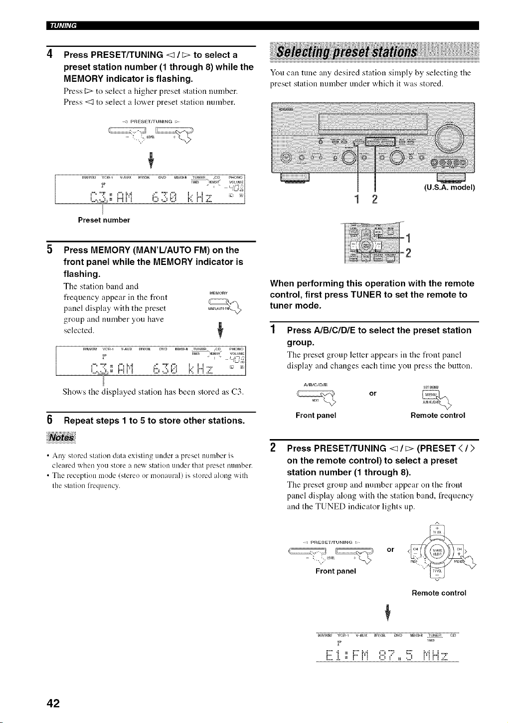
llqi'#i'i"
Press PRESET/TUNING <1 / _> to select a
preset station number (1 through 8) while the
MEMORY indicator is flashing.
Press C> to select a higher preset station number.
Press <1 to select a lower preset station number.
You can tune any desired station simply by selecting the
preset station number under which it was stored.
[
{U.S.A. model)
Press MEMORY (MAN'L/AUTO FM) on the
front panel while the MEMORY indicator is
flashing.
Tile station band and
PaEblORy
frequency appear in the front
panel display with the preset
group and number you have
selected. +
DV_VCR2 VC++1 V_UX DTV,f:_- E>W> mDseDR rUP_Em _D pHON_
+ Ll+--*_++g'
¢" ":P = ¢"+ b:{ +._' "T ¢':+ +," L+ ..... mlu
= % ++ =.a +,+
.+:+2;ig,+.. = += + +:2+.+)EJ b+ +""+.+:;+
+
Shows the displayed station has beet+ stored as (.'3.
6 Repeat steps 1 to 5 to store other stations.
• Any stored station data existing under a preset number is
cleared when you store a new station under that preset mnnber.
• The reception mode (stereo or monaural) is stored along with
the station fl'equency.
When performing this operation with the remote
control, first press TUNER to set the remote to
tuner mode.
Press A/BICIDIE to select the preset station
group.
The preset group letter appears in the front panel
display and changes each time you press the button.
Front panel
or
_mE_g
Remote control
Press PRESET/TUNING <1 / _> (PRESET < / >
on the remote control) to select a preset
station number (1 through 8).
The preset group and number appear on the front
panel display along with the station band, frequency
and the TUNED indicator lights up.
<_ pglE_ET/TUN_NG r>+
Front panel
or
Remote control
Dv_,_ vcR + v _ux m'q,r_t DVD mDCD_ TUNEr4 CD
_p _U_F.
42
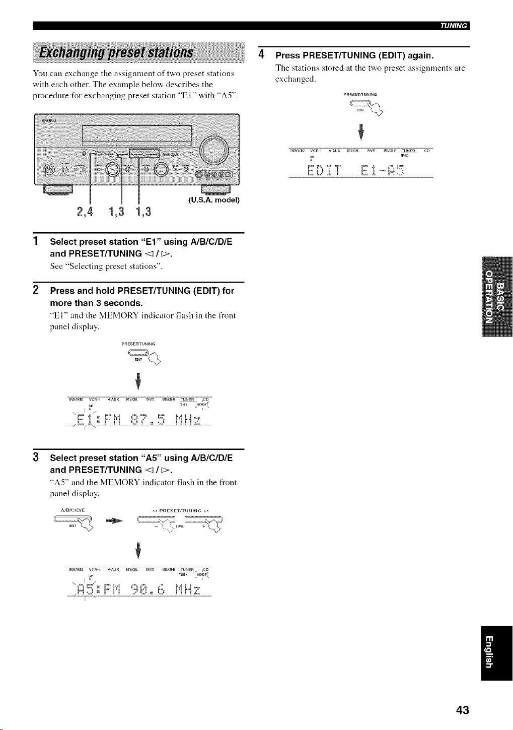
iql/h'["
You can exchange the assignment of two preset stations
with each other. The example below describes the
procedure for exchanging preset station "El" with "A5".
Press PRESET/TUNING (EDIT) again.
Tile stations stored at tile two preset assignments are
exchanged.
pRESE rn'UNING
DV_VCR2 V¢_ 1 V _UX DW,_ DVD _D _ TUNER CD
F
E ill:,i T E i .....i:::i5
2,4 1,3 1,3
(U.S.A. model)
Select preset station "El" using A/B/C/DIE
and PRESET/TUNING <1 / _>.
See "Selecting preset stations".
Press and hold PRESET/TUNING (EDIT) for
more than 3 seconds.
"El" and the MEMORY indicator flash in tile front
panel display.
D_CR_ veg 1 V AUX DIV,¢_t DVE_ _DSeD_ TUNS_ CD
I sp ru,E_ MF_0RV
Select preset station "A5" using A/BICIDIE
and PRESET/TUNING <1 / _>.
"A5" and tile MEMORY indicator flash ill the front
panel display.
_w,w_ vcR 1 v _ux _lV,e_L E_VE_ t_ _ TU_E_ ,CE_
I
43
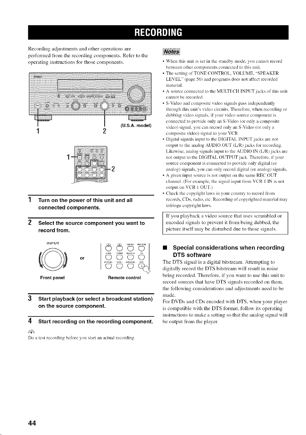
Recording adjustments and other operations are
performed from the recording components. Refer to the
operating instructions for those components.
(U.S.A. model)
1 Turn on the power of this unit and all
connected components.
2 Select the source component you want to
record from.
iNPUT
Front panel
or
© U
©
Remote control
3 Start playback (or select a broadcast station)
on the source component.
4 Start recording on the recording component.
-#.
Do a tesl recording beh)re you start an actual recording.
• When this unit is set in the standby mode. you cannot record
helween olher components connecled to this unit.
• The setting of TONE CONTROL, VOLUME, "SPEAKER
5 /_*
LEVEL" (page _6) and pr( jams does not affect recorded
material
• A source connected to the MULTI CH INPUT jacks of this unit
c_lilno| be recorded.
• S-Video and composite video signals pass independently
through this unit's video circuits. Therefore, when recording or
dubbing video signals, if your video source component is
connected to provide only an S-Video (or only a composite
video) signal, you can record only an S-Video (or only a
composite video) signal 1(!your VCR.
• Digilal signals inpul to Ihe DIGITAL INPUT jacks are nol
output to Ihe analog AUDIO OUT (L/R)jacks for recording.
Likewise, analog signals input to lhe AUDIO IN (L/R)jacks are
not output to the DIGITAL OUTPUT jack. Therefore. if your
source component is connected Io provide only digital (or
analog) signals, you can only record digilal (or analog) signals.
• A given input source is not output on the same RE(7 OUT
channeh (For example, the signal input lrom VCR 1 IN is nol
outpnl on VCR 1 OUT.)
• Check the copyright laws in your counlry I(! record from
records. CDs. radio, elc. Recording of copyrighled material may
infringe copyrighl laws.
If you playback a video source that uses scrambled or
encoded signals to prevent it from being dubbed, the
picture itself may he disturbed due to those signals.
• Special considerations when recording
DTS software
The DTS signal is a digital bitstream. Attempting to
digitally record the DTS bitstream will result in noise
being recorded. Therefore, if you want to use this unit to
record sources that have DTS signals recorded on them,
the following considerations and adjustments need to be
made.
For DVDs and CDs encoded with DTS, when your player
is compatible with the DTS t_rmat, follow its operating
instructions to make a setting so that the analog signal will
be output from the player.
44
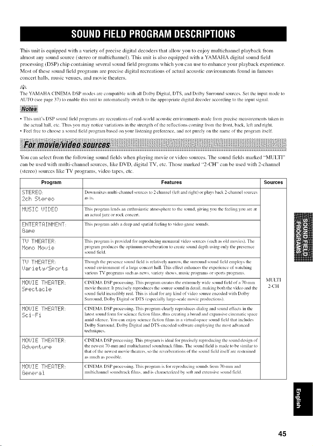
This unit is equipped with a variety of precise digital decoders that allow you to enjoy multichannel playback from
ahnost any sound source (stereo or multicham]el). This unit is also equipped with a YAMAHA digital sound feld
processing (DSP) chip containing several sound field programs which you can use to enhance your playback experience.
Most of these sound fiekt programs are precise digital recreations of actual acoustic environments found in famous
concert halls, music venues, and movie theaters.
The YAMAHA CINEMA DSP modes are compatible with all Dolby Digital, DTS. and Dolby Surround sources. Sel the input mode to
AUTO (see page 37) to enable Ibis unil Io automatically switch to Ihe appropriate digital decoder according Io the inpul signal.
• This unit's DSP sound field programs are recreations of real-world acoustic environments made from precise measurements taken in
the actual hall. etc. Thus you may notice variations in the strength of the reflections coming lrom the front, back. left and righl.
• Feel free 1o choose a sound field program based on your listening preference, and not purely on file name of the program itself.
a ....
You can select from the following sound fiekts when playing movie or video sources. The sound fiekts marked "MULTI"
can be used with multi-channel sources like DVD, digital TV, etc. Those marked "2-CH" can be used with 2-channel
(stereo) sources like TV programs, video tapes, etc.
Program Features Sources
I,:::' _ {:::.K[::; l...l: Downmixcs mtllli-channel sources Io 2 chanlw] (left and right) or plays back 2-channel sources
2,::;{q '.:!:':_;:..,ii?i"',ii?O as is.
Ir'_i_,...<...,i*:::'a.T,...=_"""...'iiTa.i..='_....,...,i"*i:::'_"_ This program lellds an enthtlsiaslic almOsl)here Io Ihe SOLIll(l, giving you Ihe feeling yotl are at
all acnlal jazz or rock concert.
I..,A_I I..=I".I I"I,[*I_I II,,,=I_ I.i'2rM"r'i'2ri:)Tl"lTMMi:ri..i"i". This prograln adds a deep and spatial feelin_ Io video game sounds.
=,
I.::_.ii_r,'!,ii?
I...l.,:'• .....' "ri i ........................... This pro_raln is provided for reproducing monaural video sources (such as old movies). The
r'ioiq,=, M_...,i.j'i_:::, prograln produces the oplimum reverberation to create sound deplh using only the presernce
sound field.
'./ _i _...r"i_i..._'..: Th( u_h the _tresence ound leld is relalively narrow, Ihe surround sound field employs Ihe
i.j.::._i.".'i ,::a'J'._...i/'::::_:::.,"ii.".']'..:::.sound environment of a large concert hall. This effect enhances Ihe experience of watching
variotls WV programs Stlch as news, variety shows, mtlsiC programs or spOllS programs.
MULTI
__,...,,...._._..."a'u, _,... __.....r..___..,a....',..a,..._,. ,..._...,. CINEMA DSP processing. This progran'_creates Ihe extremely, wMe sound field of a 70-ram
'::.':i:::._:::,,°..[.:::,c..'1,::a movie thealer, h precisely reproduces the source soulld ill detail, making both the video and Ihe 2-CH
sound field incredibly real. This is ideal for any kind of video source encoded wilh Dolby
Surround, Dolby Digital or DTS !especially large-scale movie produclions).
i _,...,......_.i..,."'h"_ii'ri:::""r'i..._i:::T','T'i:::'i:::,.ll....mll..._....CINEMA DSP processing. This 1)rogram clearly reproduces dialog and sound effecls in the
'.:!:;,:::.:i.-F:::i. latesl sound lk)rmlk)r science ficlion fihns, tiros creating a broad and exl)ansive cinematic space
amid silence. You can enjoy science ficlion films ill a virtual-space SOUlld field Ihat includes
Dolby Surround, Dolby Digital and DTS-encoded soflware elnpk)ying the most advanced
techniques.
_,....,...._._...."mu, _,... _...,.r"_..,a'..:,°a,..._,. ,..._...,. CINEMA DSP processin_._This pro_ran'_is ideal for precisely reproducin_ tile sound design of
I::i(7{LhlI?['Ti:..L.H"',II? the newest 70-mn'_and mullichannel soundtrack films. The sound field is made Io be similar Io
thai of Ihe newest movie thealers, so the reverberations of Ihe sound field ilself are restrained
as much as possible.
, i,...,'...'._.i....rch"liiT i::7 "T'L.ii:rl"_"i"i:ri=,__ i_...r"_i _...i'... CINEMA DSP processing. This l)rogram is for reproducing SOLIIIds frol]/ 7/)-lllm and
li!_,ii?i"!,ii?['%iil!]. nmllichannel soundlrack fihns, and is characlerized by, soft and extensive sound field.
1
45
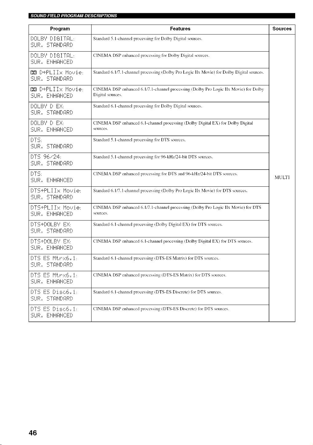
_"_o]#Aqel:71=!llel:d:[oIe_:y_,Tj¢le]=g'_ei:H_l[o]Lvp
Program Features Sources
_...',-u...._...,r" ¢°d i:::a,j_ _....r"._.T,..a¢:5a.T"i"¢"_i]r'4_ " Slandard 5. l-channel plocessin_ for Dolbv, Di_ita] sources.
....,,..21'.. :: ....' I I"41 _l...'r"ll'..l...
I...''.Jl...A...,r"t=lii:::,i.j_ _....r"._.T,..at':":.I.T"i"t"lili"4_ " CINEMA DSP enhanced processing for Dolby Digital sources.
,:::'i iiD i:::'M i..Jf"_M f" i:::T',
I']["] [)"kF:'L. i[ i[).:: ["ioL,J :i. e: Slandard 6. I/7. I-channel processing Dolbv Pro Logic llx Movie) for Dolby Digilal sources.
,:::'i ii::) ,:::'T ,"fi..i r'., ¢"fi::) r'.,
flgl L:_+I"'L..L.L::':: f'lOb_:Le: CINEMA DSP enhanced 6.1/7.l-channel processing (Dolby Pro Logic llx Movie) for Dolby
sources.
l...',.Jl..,._...,r"a=lii:::,i.j_ l....r" i..=:..:i::7%:".... Slandard 6. l-channel plocessin_ l_)r Dolbv Digital sources.
c:'JH:::, c:'"r,",J.._r.,,",J:::,r.,
_...',...q...._...,r"a%iiDi.J__...r"i..._..:.i:::'_":• CINEMA DSP enhanced 6. I-channel processing (Dolby Digilal EX) for Dolbv Digital
,:::'i ii::) i:::'Mi..Jl'_M f"i:::T ', Sotlrces.
_...'r"'T":::'_....,. Slandard 5. l-channel processing, for DTS sources.
•:::'i ii::) *:::'"T',"l i..i r'., i", i:) r'.,
_....r""i",:::_...., ,:::_,:::.......,......":,..i..,:"r. Slandard 5. l-channel processing for 96-kHz/24-bil DTS sources.
•:::'i ii::) *:::'"T',"l i..i r'., i", i:) r'.,
_....r""r':::'_....,. CINEMA DSP enhanced processing for DTS and 96-kHz/24-bil DTS sources.
MULTI
•:::'i ii::) i:::'M i..a t"l M l"' i:::"r'.,
C,"r'.!!i+F:'L.]i ]i :it:: {"il_:{ll' .l :_1 Ill?: Slandard 6.117. I-channel processing Dolbv Pro Logic llx Movie) lk)r DTS sources.
•:::'i ii::) *:::'"T',"l M r'., i", i::)r'.,
[)T".[[i+PL_]i ]i).:: Mo_..J J.,ii?: CINEMA DSP enhanced 6.1/7.l-channel processing (Dolby Pro Logic llx Movie) for DTS
,:::'i lid i:::'M i..M"d., i f" i:r r'., SOtlI'CeS.
....H..JI'.. :: I...._ 'H H..41 .I%..L.A....
l...'r""i",::["..t..r.. t"li_ ...) , i.... ,...*i...._...,ii::,i.j_ i....:.._.i:::':..;. Slandard 6. I-channel plocessillg_ {Dolbv. Digila] EX) for DTS sources.
•:::'i ii::) *:::'T ,"l i..i r'., i", i::)r'.,
_...'r"'T":::""i"'-_i_....,,_...",...,_...._...,c:a"__....,",.i:::''< CINEMA DSP enhanced 6. I-channel processing (Dolby Digilal EX) for DTS sources.
c:'JH:::, _:::'_..JJ..a,-,_..J,".J::rr.,
....H,,*q% II I,,,,_ 'II 11"41 'I_,,,,L..I,,,'
C'TI.!!; [!!!S lI[Jli:'lilllI:lll:]l'[[ ' 1' ]lI: Slandard 6. l-channel processing (DTS-ES Malrix) for DTS sources.
,:::'i ii:::, ,:::'"r',"_i..ir'.,¢",i:::,r'.,
{_:]"rl'_ 1_'_ 11[jl[T,{1111:i'i:]i_[' 1, 2L: CINEMA DSP enhanced processing (DTS-ES Matrix) lk)rDTS sources.
C'"r'.!!i [!!!S L?:i.:_X.I:.!!,,, i : Slandard 6. I-channel processing (DTS-ES Discrele) for DTS sources.
•:::'i ii::) *:::'"i" t"l i..ir'., i"t i:) r'.,
[)'T".[[i[[[!S 1)J.:E.G6,, i: CINEMA DSPenhanced processing(DTS-ES Discrete) for DTS sources.
,:::'i ii::) i::7i.. ii..af"_M f" i::rr'.,
46
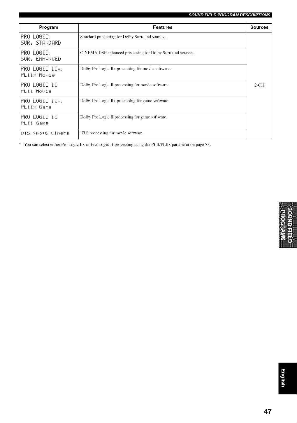
_:e.I#Jdlel_l=!llel:d:[eIef:L, yj¢le]=_..".iei:H_l[e]d_
Program Features Sources
i:::fi:::,f"li ".._..., i...._...,,...lif"H'::: ._.T,.....f'" S 181]dill'(] pl"o_:_.'_;S]l] _ for Dolbv. SLirrotl[]d SOLII'C CS.
i:::_i:2*f"tl..._...,l...._...'_...lif"t f::: ._.T'....+t"'+ CINEMA [)_P _..[]hal]ccd pl_Ccss]i]g fOl Dolby SUITOLII]d _()UFC_.'_+
'::_iii:;?.. _::'i'..ii..417_Hf":i:::i":_
i::'i:2*f"t...................i _".':::T ,". .....T'r....... Dolby Pro Logic llx ploc_-'_,_,il]gfor lllovie _,ol'Pwar__..
i_:_i T T. • P'It"tl. i 'I I:::,
, i,,. ,i, ,. ,,,,
F::'F;?J]] L.,,O(!!i ]] l]]: ]]]]: Dolby Pro Logic ll processing for movie sol]ware. 2-CH
i_:_i T T _"I f"t i, i '_ I:::,
,i:::'i:::,f"li".J.,,, i,,._,,,,,,,,li_".':::._T,....'"._'r...'r'.....'" Dolbv Pro Logic llx processing 1()1_8111_:so[t Wal_.,.
i:::qi i!i:: _.::i.ii_r,_e
li::fi:::'f"lI ".J...' I....'...'_...li_".'::: ._.T'...._" ._.T._.T." Dolby Pro Logic 11 proccsSil]_ l_)r galnC soflware.
[)"i"S: H,IX, 116 (]::i.i"!ei'q.ii_ DTS processing for movie sof[ware.
You can selec( eilher Pro Logic llx or Pro Logic II processing using the PLII/PLIIx parame[er on page 78.
47
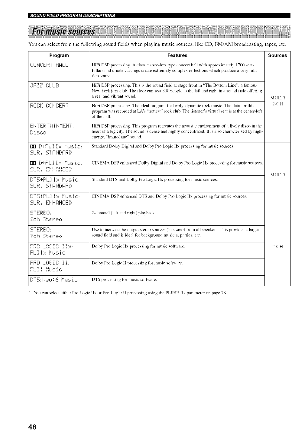
_"_o]#hVel:71=!llel:J:[oIe_:y_,Tj¢lel=g'_ei:H_l[o]Lvp
You can select from the following sound fields when playing music sources, like CD, FMiAM broadcasting, tapes, etc.
Program Features Sources
_....'...qI" 1%H I"' i:::"i:::,"r'".%..I..,A"* I li"Jl"iilI"I l....li.... HiFi DSP processing. A classic shoe-box Ivpc.conccrl hall wilh approxilnalelv. 1700 scats.
Pillars and orllale carvings creale extremely complex reflections which produce a very full,
rich sound.
'i',"_"::'"::_ _".i i ii::, HiFi DSP processing. This is Ihe sound field al slaae front in "The Bottom Line", a famous
New York jazz chlb. The floor can seat 300 people Io Ihe lefl and right in a sound field offering
a real and vibrant sound. MULTI
_...,...-...*_...i:::'""'i"',....,...,_"'_"'i"h"'_::'i:::'"r'.-...*_...._'.._ HiFi DSP processing. The ideal program lk)r lively, dynamic rock music. The data lk)r Ihis 2-CH
program was recorded at LA's "hottest '' rock club. The listener's virtual seat is at the cenlerqefl
of Ihe hall.
_....H_'',.a _ _...._r'*_"'...'_ r"_' ._._".q_,..m_..._..._'_"'_ ." HiFi DSP processing. This program recreales the acoustic environmenl of a lively disco in the
{":_'i .:::a".,"_ heart of a big city. The sound is dense and highly concenlrated. It is also characterized by high-
energy "imlnediale '_ sotlnd.
1"]["1C'"{"F:'L.i[ iil).:: ["ii...i:ill• :i.c.: Slandard Dolby Digilal and Dolby Pro Logic llx processing for music sources.
•='i ii=, *='"i"¢"I M r'., i"fi=, r'.,
fin L:'+{"'L..L .L?':: Pli...i:ii_.:L(::.: CINEMA DSP enhanced Dolby Digital and Dolby Pro Logic llx processing for music sources.
MULTI
r'.,"r',:::..,..i::.i............... T T..,* {"iiJ*:::.i ,".. Slandard DTS and Dolbv. Pro Logic llx processing for music sources.
•='i ii=, *='"i","l i..i r'., i", i=, r'.,
r'.,"i",:::_..,..i::)i........... T T...* Mi .i*:::.i ,%. CINEMA DSP enhanced DTS and Dolby Pro Logic llx processing for music sources.
....................'::::"H:::'{:;)]:::'I"I" 2-channel (left and right) playback.
'.:::,I 1:::.{',:'.1:::I...I: Use to increase Ihe output stereo sources (in slereo) from all speakers. This provides a larger
•?G['3 '.!!:'_'[:.._ii'i"*,iX, sound field and is ideal l_)r background music al parlies, elc.
i:::,i2u"l...............i i"il':::'['_....i== ....T'r..... Dolbv. Pro Logic llx processing for music software. 2-(-'H
l:::'i...,i i >: MJ.._:II_.J.,:::.
li:::'i:::'i"ll'=='...'I..,*'..."...I ._*'...*iI-if::: T i"* .I.T._..'r" Dolby Pro Logic lI processillg for music sol]ware.
l:::'i...,i i l"i_...i:ii_.:i.,:::.
[;,"i2!;:l".i,li?,:::,',',6 l"ii...i:ii_.:i.,:::.DTS processing lk)r music soflware.
You can select eilher Pro Logic llx or Pro L%.lC 11 process]n0 usmv tl_e PLII/PLIIx parameter on page 78.
48
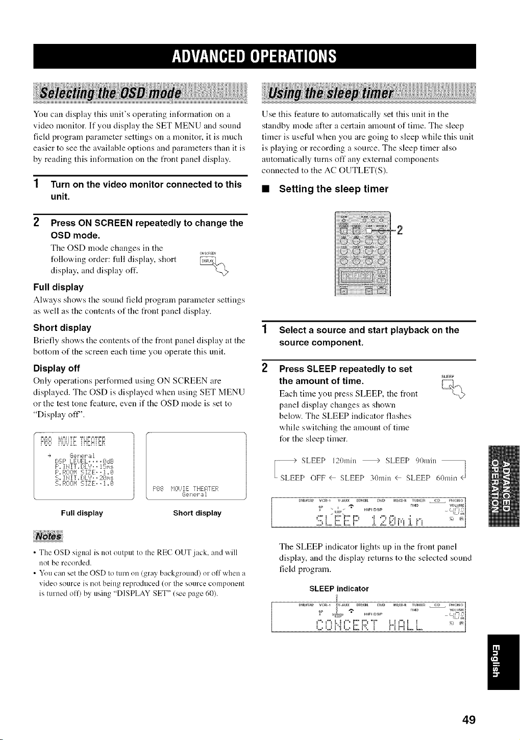
You can display this unit's operating int_rmation on a
video monitor. If you display the SET MENU and sound
field program parameter settings on a monitor, it is much
easier to see the available options and parameters than it is
by reading this int_rmation on the front panel display.
1 Turn on the video monitor connected to this
unit.
2 Press ON SCREEN repeatedly to change the
OSD mode.
The OSD mode changes in the
0NSCREEN
following order: fllll display, short _,
display, and display off.
-%
Full display
i !!!iii
Use this feature to atttomatically set this unit in the
standby mode after a certain amount of time. The sleep
timer is useful when you are going to sleep while this unit
is playing or recording a source. The sleep timer also
automatically turns off any external components
connected to the AC OUTLET(S).
• Setting the sleep timer
Always shows the sound field program parameter settings
as well as the contents of the front panel display.
Short display
Briefly sho'a,s the coutents of the front panel display at the
bottom of the screen each time you operate this unit.
Display off
Only operations performed using ON SCREEN are
displayed. The OSD is displayed when using SET MENU
or the test tone feature, even if the OSD mode is set to
"Display ofF'.
P>=I P'i_=]iT; TUbUlE
[:,SF' LEUEL, ,, ,gdB
F'. iiIIT,,DLV,, !5_,s
F',,ROOM 5 XZE,, 1 ,,0
S,, !11IT,, [!L'?,, 2€11,i:_
% nO011 S IZ E., i ,,0
F'O8 HOIJIE TFIEATER
GeYJet El1
Full display Short display
1 Select a source and start playback on the
source component.
2 Press SLEEP repeatedly to set
the amount of time. _....
r-;].,
Each time you press SLEEP, the front '_<@
panel display changes as shown
below. The SLEEP indicator flashes
while switching the amount of time
for the sleep timer.
I7d 2;2Z&2/72;;,.J
• The OSD signal is not output to the REC OUT.jack. and will
not be recorded.
• You can set the OSD to turn on (gray background) or oil when a
video source is not being reproduced (or the source component
is turned oil) by using "DISPLAY SET" (see page 60).
The SLEEP indicator lights tip in the front panel
display, and the display returns to the selected sound
field program.
SLEEP indicator
:,.,,:,J_'_L,,i;2 9: _ i' 'i H L i....
I
49
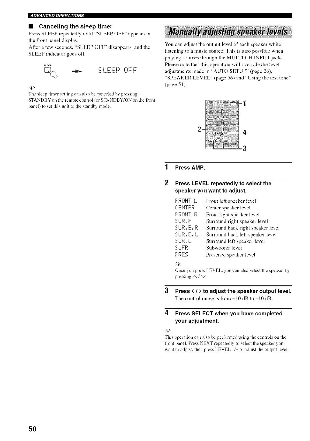
W__yeJrl_q,ffPi_ple]'.J:/:yzWl[e],v_
• Canceling the sleep timer
Press SLEEP repeatedly until "SLEEP OFF" appears in
the front panel display.
After a few seconds, "SLEEP OFF" disappears, and the
SLEEP indicator goes oft'.
SkEEP
t"' 1 i"' i"' i"n t"1 i"' 1....
The sleep timer setting can also be canceled by pressing
STANDBY on the remote control (or STANDBY/ON on the l?ont
panel) to set this unit to the standby mode.
You can adjust the output level of each speaker while
listening to a music source. This is also possible when
playing sources through the MULTI CH INPUT jacks.
Please note that this operation will override the level
adjustments made in "AUTO SETUP" (page 26),
"SPEAKER LEVEL" (page 56) and "Using the test tone"
(page 51).
1 Press AMP.
2
Press LEVEL repeatedly to select the
speaker you want to adjust.
i l'..n...ll .i i 1
r'.i2'i..i*'i"i;;;'i2,
i;;7i2u'_lM "T' i2,
_;;;'i ii2, i2,
_iii_i iiii_ i:ii_ iii_
_iii_i iiii_ ill) i
qi ii;?..i
...., ,.,.q i'..
i i'..i........,
Front left speaker level
Center speaker level
Front right speaker level
Surround right speaker level
Surround back right speaker level
Surround back left speaker level
Surround left speaker level
Snbwoofer level
Presence speaker level
Once you press LEVEL, you can also select the speaker by'
pressing A / v.
3 Press < / ;, to adjust the speaker output level.
The control range is from +10 dB to -10 dB.
4 Press SELECT when you have completed
your adjustment.
_%,._
This operation can also be performed using the controls on the
front panel. Press NEXT repeatedly to select the speaker you
want to a@lst, then press LEVEL _+ to a@lst the output level.
50
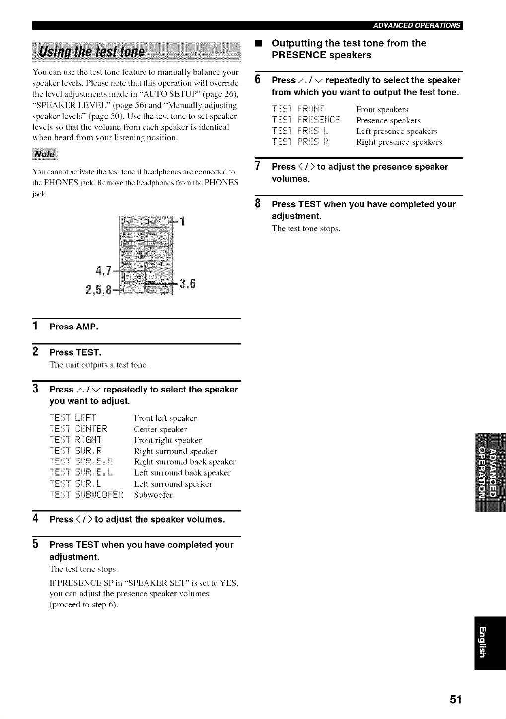
You can use the test tone feature to manually balance your
speaker levels. Please note that this operation will override
the level adjustments made in "AUTO SETUP" (page 26),
"SPEAKER LEVEL" (page 56) and "Manually adjusting
speaker levels" (page 50). Use the test tone to set speaker
levels so that the volume from each speaker is identical
when heard from your listening position.
YOU cannol activate the test lono i[ headphones are connocled 1o
the PHONES jack. Remove the headphones fronl the PHONES
jack.
=1
4,7=
2,5,8- -3,6
_yeJ_/__y,v[Pl:lPlo]'.1:l:y__|llo],v_
• Outputting the test tone from the
PRESENCE speakers
Press A / v repeatedly to select the speaker
from which you want to output the test tone.
*T'i!!'.!!!;"i"FrR0i"i"i" Front speakers
"r'ixr_:::"T' i:)+:::,i:::',:,"i::rMl=*i::r Presence speakers
*'J"J:rC"r'ix, D::: J Left presence speakers
i L,_.,, I i I i',,I,,,,,,,, l i
TE!!!!;T F:i:;I:i!!!ISF;;: Right presence speakers
7 Press < / ) to adjust the presence speaker
volumes.
8 Press TEST when you have completed your
adjustment.
The test tone stops.
1 Press AMP.
2 Press TEST.
The unit outputs a test tone.
3 Press A / v repeatedly to select the speaker
you want to adjust.
, _......, _ _...i...i I
"i%::',:::'"V ,:::'i ii:::, i:::,
'TF'q'T ':::;iiF;'..F',.. F;'
"i%::',:::'"V ,:::'i ii:::, i:::, i
"i"i:::',:::'"V ,:::'i ii:::, i
i,,, t,,, _,,, i 1i,,31 ,i i ii i i,,, i,,, t,,,i
Front left speaker
Center speaker
Front right speaker
Right surround speaker
Right surround back speaker
Left surround back speaker
Left surround speaker
Subwoofer
4 Press < / ) to adjust the speaker volumes.
5 Press TEST when you have completed your
adjustment.
The test tone stops.
]f PRESENCE SP in "SPEAKER SET" is set to YES,
you can adjust the presence speaker vohnnes
(proceed to step 6).
51
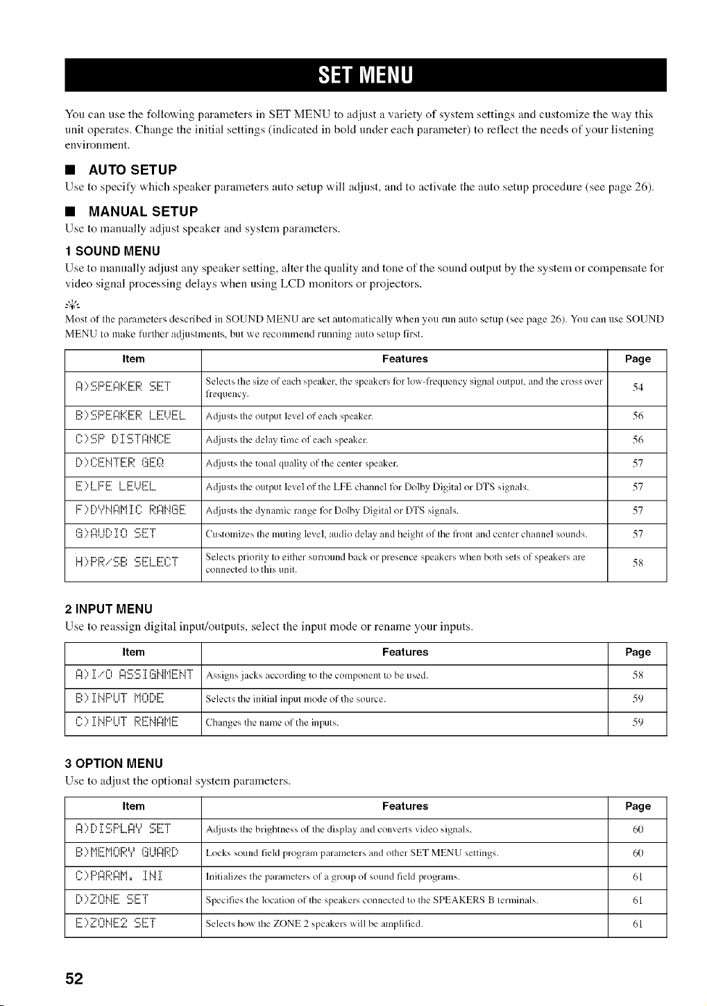
You can use the following parameters in SET MENU to adjust a variety of system settings and customize the way this
unit operates. Change the initial settings (indicated in bokt under each parameter) to reflect the needs of your listening
envkonment.
• AUTO SETUP
Use to specify which speaker paralneters auto setnp will adjllst, and to activate tile auto setnp procedure (see page 26).
• MANUAL SETUP
Use to manually adjust speaker and system parameters.
1 SOUND MENU
Use to mannally adjust any speaker setting, alter tile quality and tone of tile sound ontpnt by tile system or con]pensate tot
video signal processing delays when using LCD monitors or proiectors.
_.,#._
Most of the parameters described in SOUND MENU are sel automatically whell yotl rlln auto setup (see page 26). You can use SOUND
MENU It) make hmher adjustmenls, but we reconlmend running auto selup first.
Item Features Page
I:'4::':!!!;F::'EI:::Ii':::i!!!R'.!;ET s¢.k.cts the size of each speaker, Ihc speakers lk)r lowqYcquency signal outpul, and Ihe cross over 54
freqtlency.
i:::I "l 4::'i:::d:::'t"d."q:::_i:::' i i::Ti ii::Ti A([jusIs Ihe output level of each speaker. 56i,,.i.,'.,,,11 i,,,,_"ii'..i,,,.i',, i,,,.i,,,.',,,'i,,,.i ....
',,..l="",,:::'i::_,,,.,,'I _,,'r"'r '::"T I"d"h'_'i:::'a.....,i r"u".,,...._.... AI.lju st s Ihe delay time of each speaker. 56
_....r"*..."*...._...__".i::ri..i"i"i::ri:::,.___...r.. *...u...,.:<_':::i::r¢'_ A({iusts Ihe tonal qualily of the cenler speaker. 57
_......_...._i:r".,i i:ri:::'_...._...a........_...._ii:ri u:::'i.... A_liusls Ihe output level of the LPE channel for Dolby Digital or DTS signals. 57
,""..."_.,,..u..._...._ w,r",,'m_._.'*...._' ,'..,".,_,...,,u..,,..:,...v..a,. A_{iusts Ihe dynamic range lk)r Dolbv_ Digilal or DTS signals. 57
,:': '.,_",iit'.,T,=_ ¢:'i:::'"r
,..a...m,...,_..'.i.,..., ...,_...._ Customizes Ihe muting level, audio delay and height of Ihe front and center channel sounds. 57
i..J"l{:::li::,..'*:::'i::,*:::'t:::'ii:::'l"'"i= Selects priorilv Io either surrotlnd back or presence speakers when both sets of speakers are
connected Io this unit.
2 INPUT MENU
Use to reassign digital input/ontpnts, select tile input mode or rename your inputs.
Item Features Page
r'_..'1")IIiiIiIIT.." {"ll.iiir'_ ,,,.l.,,,1,1, I,,,l [ ] li") i::_i:::' T i::: i..ii'l'ii:::"H "r'iI..,A "., i Assigns jacks according to Ihc COlilponenl to be tlscd. 5_
D "l T Mi:::,i i"i" M_"li%i:::
_...,..' ._._"u *...,_ _ _,........_.... Selects tile inilial inpul mode of the source. 59
I'=" ", T Mi:::,i i"i_ i:::,i:::'i..h")i','ii:::"
,......'.i.i ".q *...,_ r.._....i".q".qu Changes tile ilame of tile inpljIs. 59
3 OPTION MENU
Use to adjust the optional system parameters.
Item Features Page
I"_1")",,,, I,,"1"',[.T .,,,' It]::' t::) iI,,,. r'_i")i,,II ,,,.q,,,.':::"i:::" TI A([iLISt S file brightness of file display {llld convl:rt s video signals. 60
D ", Mi::rh'i_"d:::d.J _':::i i¢')i:::,P',
,...,..._ ,,...._,,...,,.. _ ,...,,...,,..'.,v..,.... Locks sound field program paralnelers and olher SET MENU settings. 60
_==", D _% i:::u"Hyi T H T
,......'_ r".,v..r". _=, ._._".,._. hlilializes the parameters of a group of sound fieM progralns. 61
_.......,:...,...,H_....i"*'.,"::q'-_i..ii:::'....,_....':::'i:::"T'_ Specifies the location of tile speakers connected to tile SPEAKERS B lerminals. 61
1!!)Z I:)['.1[!!:2 SET Selects how Ihe ZONE 2 speakers will be alnplified. 61
52
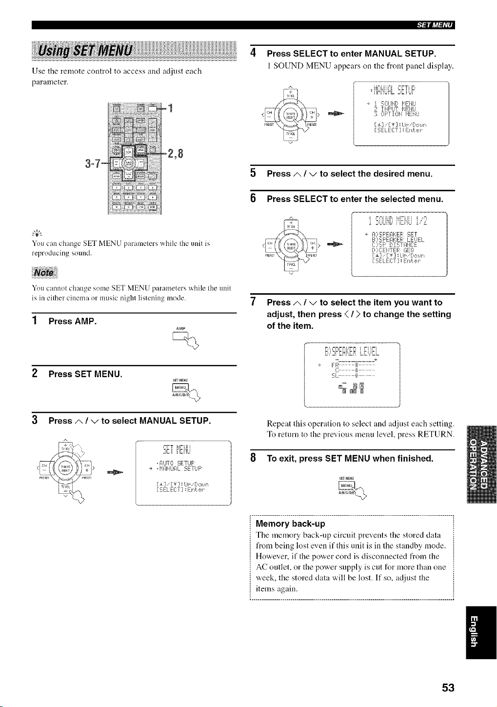
Use the remote control to access and adjust each
parameter.
-1
.... -2,8
3-7-
You can change SET MENU parameters while Iheunit is
reproducing sound.
Press SELECT to enter MANUAL SETUP.
1SOUND MENU appears on the front panel display.
s
, i',{_%JiJ_°_i,2L'TiiE,
=i i,'_i%W_=%i :J{
i 50LII,/D I,IEilLI
2 iilF'UT i'/ENLI
30F'TiOH HEHLI
[ £]/[T] sLIF/Do_.!_,
[SELECT] Er,(er
5 Press/,. / v to select the desired menu.
6 Press SELECT to enter the selected menu.
_%=,iILI,'=,, _,,[i'i, H } ,i ,-"_
a FO:SF'EIqKEF: 5;ET
B :,15F'E_,EEF,I LEUEL
C ':;F' [:,! 5TF, IE:E
I::,)C:Ei/TE F,: L:iEQ
F±] FT] kll: [,o! h
[ SELECT ] : Erd.er
You cannot change some SET MENU parameters while the unit
is in either cinema or music nighl listening mode.
1 Press AMP.
Press SET MENU.
Press A / v to select MANUAL SETUP.
;,Ci iEi'gJ
, AUTO C;ETLIF'
-+ ,$,I}7,11UI:ILSETUP
E_] 'Ev] Lr_ Pct,_,
[SELECT] :Ehte_
Press A / v to select the item you want to
adjust, then press < / > to change the setting
of the item.
%. ............................ d"
FF,:......... [I...........
C.............il.............
_.L...............!i...............
_Z _
Repeat this operation to select and adjust each setting.
To return to the previous menu level, press RETURN.
8 To exit, press SET MENU when finished.
Memory back-up
The memory back-up circuit prevents the stored data
from being lost even if this unit is in the standby mode.
However, if the power cord is disconnected from the
AC outlet, or the power supply is cut for more than one
week, the stored data will be lost. If so, adjust the
items again.
....................................................................................................... ,
53
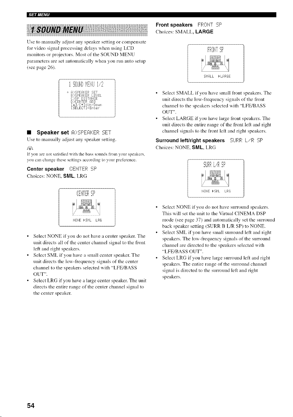
IFl_llliff_Ir
i! ! !!
Use to manually adjust any speaker setting or compensate
for video signal processing delays when using LCD
monitors or projectors. Most of the SOUND MENU
parameters are set automatically when you run auto setup
(see page 26).
i 2t,Lqb iu,.i'u,]i, ,_:
÷ FO£;F'EJ:,KER :-;E7
B)5;FEF, KER LEUEL
C],SP B,[ 5;TF,Ia3E
['?C E}_TER GEO
r,-ELECT] Enter
• Speaker set ,v.:::_:::,c:,-,__:::Dc c:r
Use to manually adjust any speaker setting.
_.,#._
If you are nol satislied with the bass solnds h'onl youl"speakers,
you can change these seltings according to your preference.
Center speaker ,".:'u"r_::D ,:::'_::,
Choices: NONE, SML, LRG
F,,'__ IY FF_ _=F_
L,F=,i'iiF=,R2¢
HOIE kSHL LFqG
• Select NONE if you do not have a center speaker. The
unit directs all of the center channel signal to the front
left and right speakers.
• Select SML if you have a small center speaker. The
unit directs the low-frequency signals of the center
channel to the speakers selected with "LFE/BASS
OUT".
• Select LRG if you have a large center speaker. The unit
directs the entire range of the center channel signal to
the center speaker.
Front speakers i:::'i:;;:i:[_i".i"i":!!!;i:::'
Choices: SMALL, LARGE
FF=F=[IT _=F=
FRUI'Ii 2¢
SHILL IH_F,RGE
• Select SMALL if you have small front speakers. The
unit directs the low-frequency signals of the front
channel to the speakers selected with "LFE/BASS
OUT".
• Select LARGE if you have large front speakers. The
unit directs the entire range of the front left and right
channel signals to the front left and right speakers.
Surround left/right speakers :!!!;Lii:;;:i:;;:L"R :!!;F:'
Choices: NONE, SML, LRG
,=_ili,i, _,,r, ,-r,
=,ur,,r,,l=,,"i, 2¢
i4L-IIE _2;i'lL LRG
• Select NONE if you do not have surround speakers.
This will set the unit to the Virtual CINEMA DSP
mode (see page 37) and automatically set the surround
back speaker setting (SURR B L/R SP) to NONE.
• Select SML if you have small surround left and right
speakers. The low-frequency signals of the surround
channel are directed to the speakers selected with
"LFE/BASS OUT".
• Select LRG if you have large surround left and right
speakers. The entire range of the surround channel
signal is directed to the surround left and right
speakers.
54
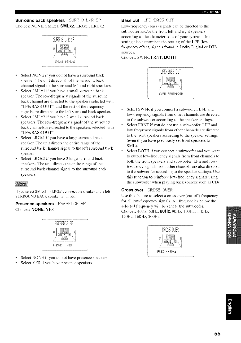
Surround back speakers ,:::i_::,_:::,i::,i .4:::,,:=::,....,,...q'.A'.. l.J I....' I'......q
Choices: NONE, SMLxl, SMLx2, LRGxl, LRGx2
_=HF=F= F= i ,,_'4"==%==
,= %q M ,, i=,, i,,
5;HL::<! k 5;HL:::::2
• Select NONE if you do not have a surround back
speaker. The unit directs all of the surround back
channel signal to the surround left and right speakers.
• Select SMLxl if you have a small surround back
speaker. The low-frequency signals of the surround
back channel are directed to the speakers selected with
"LFE/BASS OUT", and the rest of the frequency
signals are directed to the left surround back speaker.
• Select SMLx2 if you have 2 small surround back
speakers. The low-frequency signals of the surround
back channels are directed to the speakers selected with
"LFE/BASS OUT".
• Select LRGxl if you have a large surround back
speaker. The unit directs the entire range of the
surround back channel signal to the left surround back
speaker.
• Select LRGx2 if you have 2 large surround back
speakers. The unit directs the entire range of the
surround back channel signal to the surround back
speakers.
If you select SMLx I or LRGx 1, connect the speaker to the lelt
SURROUND BACK speaker terminals,
Presence speakers F:'F;;'.I!!!I:!!!:i![NCi!!!I:!!!:F:'
Choices: NONE, YES
F=F=,'===F_ IF,F ==F=
FRE,5ii'iL,I ,IF
}AL, ,. '?E5
• Select NONE if you do not have presence speakers.
• Select YES if you have presence speakers.
l_ll?tl=h'r
Bass out L..Fri!!I/E!q::iS!!!;OL.iF
Low-frequency (bass) signals can be directed to the
subwoofer and/or the front left and right speakers
according to the characteristics of your system. This
setting also determines the routing of the LFE (low-
frequency effect) signals found in Dolby Digital or DTS
sources.
Choices: SWFR, FRNT, BOTH
/
Sit F F,: F F,:iIT} _-a]TH
• Select SWFR if you connect a snbwoofer. LFE and
low-frequency signals from other channels are directed
to the subwoofer according to the speaker settings.
• Select FRNT if you do not use a subwoofer. LFE and
low frequency signals from other channels are directed
to the front speakers according to the speaker settings
(even if you have previously set front speakers to
SML).
• Select BOTH if you connect a subwoofer and you want
to output low-frequency signals from front channels to
both the front speakers and subwoofer. LFE and low-
frequency signals from other channels are also directed
to the snbwoofer according to the speaker settings. Use
this function to reinforce low-frequency signals using
the subwoofer when playing back sources such as CDs.
Cross over Ci:;;:0:!!!::!!;0i.)El:;i:
Use this feature to select a cross-over (cut-off) frequency
for all low-frequency signals. All frequencies below the
selected frequency will be sent to the subwoofer.
Choices: 40Hz, 60Hz, 80Hz, 90Hz, 100Hz, l l0Hz,
120Hz, 160Hz, 200Hz
i '.'=.'I]qk I ! I/.b'
;J@,i,
55
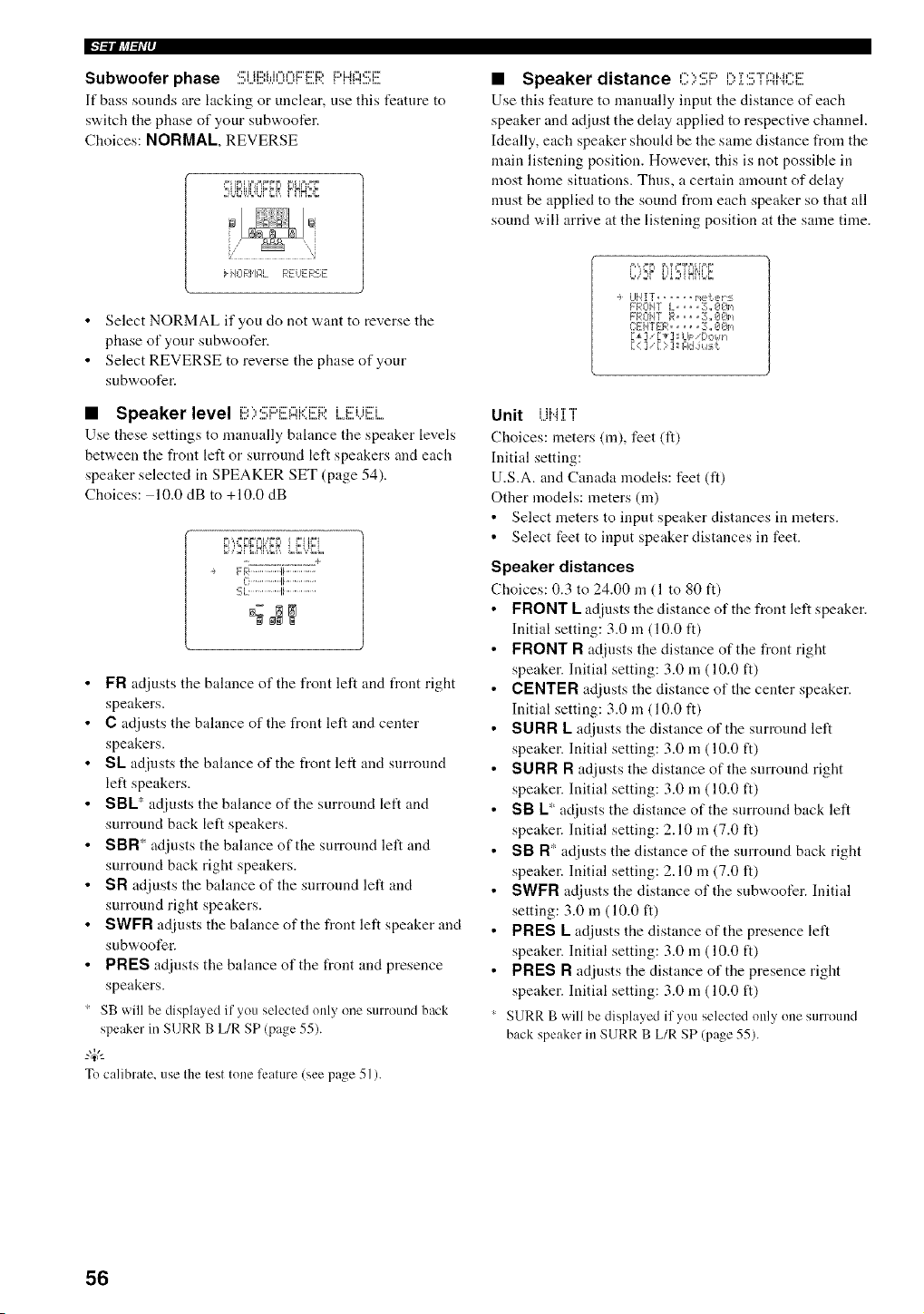
IFl_lllJl_Ir
Subwoofer phase :!!!;Ui!!!li.:.IlI)II)FE{:;?.PHASF
If bass sounds are htcking or unclear, use this feature to
switch the phase of your subwoofer.
Choices: NORMAL, REVERSE
_=,iIL'LI I IL i= L' L'_I I==,L
,=%q=%n=%qL,B, i ii,'=.'i_
kHORHF,L REHERSE
• Select NORMAL if you do not want to reverse the
phase of your subwoofer.
• Select REVERSE to reverse the phase of your
subwoofer.
• Speaker level i3;,SF:'EFIi::]!ER i...EUiEEi..
Use these settings to manually balance the speaker levels
between the front left or surround left speakers and each
speaker selected in SPEAKER SET (page 54).
Choices: 10.0 dB to +10.0 dB
FI',n=FIFFIb'FFI i F'I ii_i
Cq,]_FF Hr,,F i L,r'2,qF2,L
FR).............ti..............
C:...............li..............
SL. ..............Ii...............
FR adjusts the balance of the front left and front right
speakers.
C adjusts the balance of the front left and center
speakers.
SL adiusts the balance of the front left and surround
left speakers.
SBL* adiusts the balance of the surround left and
surround back left speakers.
SBR* adjusts the balance of the surround left and
surround back right speakers.
SR adjusts the balance of the surround left and
surround right speakers.
SWFR adiusts the balance of the front left speaker and
subwoofer.
PRES adinsts the balance of the front and presence
speakers.
SB will be displayed if you selected only one surround back
speaker in SURR B L/R SP (page 55).
-'W'-
To calibrate, use the test tone feature (see page 51).
• Speaker distance C)SF:'i>Z:!!!;TAiqC:E
Use this feature to manually input the distance of each
speaker and adjust the delay applied to respective channel.
Ideally, each speaker should be the same distance from the
main listening position. However, this is not possible in
most home situations. Thus, a certain amount of delay
must be applied to the sound from each speaker so that all
sound will arrive at the listening position at the same time.
÷ UHIT ...... i,et er:s
FROHT L= == =E;,,@@_,_
FRCIUF [4,1.... 3,, OOm
C:ENTER ..... 3:,,iIO_-
1_ ]' [ _] I LII='[)ok _1
[< ] '[ ) ] FldJu:_,¢
Unit UI4 ]Yl
Choices: meters (m), feet (fl)
Initial setting:
U.S.A. and Canada models: feet (ft)
Other models: meters (m)
• Select meters to input speaker distances in meters.
• Select feet to input speaker distances in feet.
Speaker distances
Choices: 0.3 to 24.00 m (1 to 80 ft)
FRONT L adiusts the distance of the front left speaker.
Initial setting: 3.0 in (10.0 ft)
FRONT R adjusts the distance of the front right
speaker. Initial setting: 3.0 m (10.0 ft)
CENTER adjusts the distance of the center speaker.
Initial setting: 3.0 m (10.0 ft)
SURR L adjusts the distance of the surround left
speaker. Initial setting: 3.0 m (10.0 ft)
SURR R adiusts the distance of the surround right
speaker. Initial setting: 3.0 m (10.0 ft)
SB L* adjusts the distance of the surround back left
speaker. Initial setting: 2.10 in (7.0 it)
SB R* adjusts the distance of the surround back right
speaker. Initial setting: 2.10 m (7.0 it)
SWFR adjusts the distance of the subwoofer. Initial
setting: 3.0 m (10.0 ft)
PRES L adjusts the distance of the presence left
speaker. Initial setting: 3.0 m (10.0 ft)
PRES R adjusts the distance of the presence right
speaker. Initial setting: 3.0 m (10.0 ft)
SURR B will be displayed if you selected only one surround
back speaker in SURR B L/R SP (page 55).
56
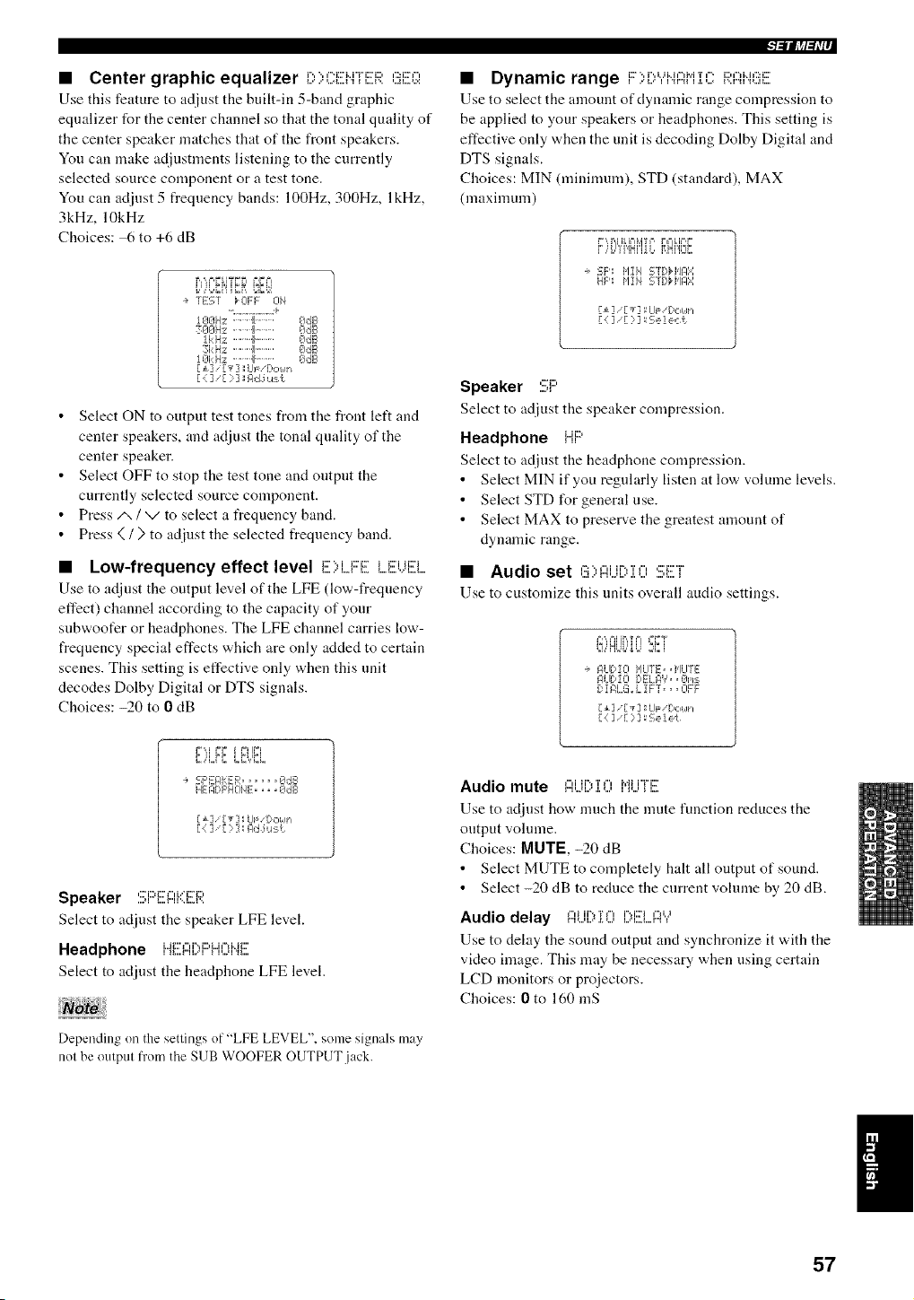
• Center graphic equalizer E:,)(?E>HER(!_EQ
Use this feature to adjust the built-in 5-band graphic
equalizer for the center channel so that the tonal quality of
the center speaker matches that of the front speakers.
You can make adjustments listening to the currently
selected source component or a test tone.
You can adjust 5 frequency bands: 100Hz, 300Hz, lkHz,
3kHz, 10kHz
Choices: 6 to +6 dB
u,,n,= ;HL=_ b&il
- TEST _CIFF 014
•-.......... +
1__J€_Hz . . . Ib..... 9dB
3_l_lHz .,, II....... I)dB
1_k HE!,...Ib ........ EIdB
3kHz '''11 ......... E_IdE,
1Et:H;:: ........ gJdE,
[ ±] ,[_-] LIp 'r)otl_/
[ { ], [ ) ] Elide u:_('.
• Select ON to output test tones from the front left and
center speakers, and adjust the tonal quality of the
center speaker.
• Select OFF to stop the test tone and output the
currently selected source component.
• Press/x / v to select a frequency band.
• Press (/) to adjust the selected frequency band.
• Low-frequency effect level E)LFE LEUi!!!i..
Use to adjust the output level of the LFE (low-frequency
effect) channel according to the capacity of your
subwoofer or headphones. The LFE channel carries low-
frequency special effects which are only added to certain
scenes. This setting is effective only when this unit
decodes Dolby Digital or DTS signals.
Choices: -20 to 0 dB
SF'EIqKER...... OdB
HEFDF'HONE.... EIdB
ri] r_] L_ [:<t,n
[.] ] [ : ] _Iqd :iu s
Speaker :!!;i:::i!!!):::Ii'(i!![R
Select to adjust the speaker LFE level.
Headphone iiE:I:::IDF::'HOi'4E
Select to adjust the headphone LFE level.
Depending on the settings of"LFE LEVEL", some signals may
nol be output from the SUB WOOFER OUTPUT jack.
• Dynamic range F)[)","i"iI:?HiC Rl::?i"i(!!iE
Use to select the amount of dynamic range compression to
be applied to your speakers or headphones. This setting is
effective only when the unit is decoding Dolby Digital and
DTS signals.
Choices: MIN (nlininmm), STD (standard), MAX
(maximum)
i ,,i,_l_l_lr,11_, 1.1_., L
?,,'i.,'_'i'iN'ffL,_,Hi'iEJ_
e 'EF': i,lIiq SrE, iq,/l:l:::i
HE' l,lii4 5TC,i,l,llq:q
[ ::i] [ : ] S e ! e,::i:
Speaker :!!El:::'
Select to adjust the speaker compression.
Headphone HP
Select to adjust the headphone compression.
• Select MIN if you regularly listen at low volume levels.
• Select STD for general use.
• Select MAX to preserve the greatest amount of
dynamic range.
• Audio set '::"'i ii..,T,, ,:::_::r
Use to customize this units overall audio settings.
1, ,n JNu, H I ii
÷ P,UDZO i'ILITE, q'ILITE
Pur!zo DELIq",',, Elns
DIIqLG.,LIF "r , ,OFF
[ ] '[:_3 Se]e{
Audio mute I:::IUDi 0 MiM!![
Use to adjust how much the unite function reduces the
output volume.
Choices: MUTE, -20 dB
• Select MUTE to completely halt all output of'sound.
• Select -20 dB to reduce the current volume by 20 dB.
Audio delay l:::li,iD :[(] i:)i!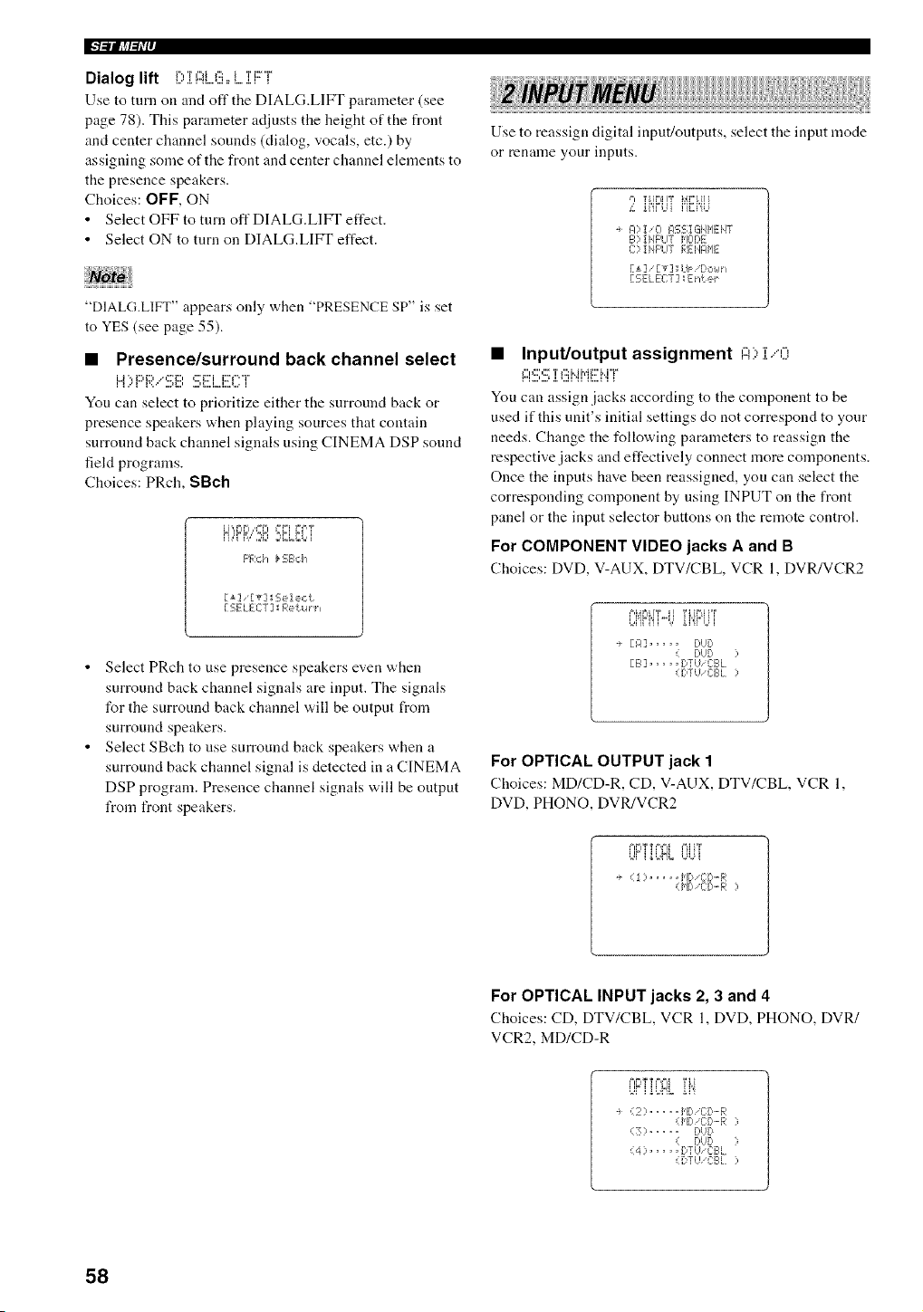
IFl_lllJff_Iv
Dialog lift D i l::iLEi,, i....i i:::T
Use to turn oil and oft" the DIAL(;.LIFI' parameter (see
page 78). This parameter adjusts the height of the front
and center channel sounds (dialog, vocals, etc.) by
assigning some of the front and center channel elements to
the presence speakers.
Choices: OFF, ON
• Select OFF to turn off DIALG.LIFT effect.
• Select ON to turn on DIALG.LIFT effect.
"DIALG.LIFT" appears only when "PRESENCE SP" is set
to YES (see page 55).
• Presence/surround back channel select
You can select to prioritize either the surround back or
presence speakers when playing sources that contain
surround back channel signals using CINEMA DSP sound
field programs.
Choices: PRch, SBch
=M_L=&= "J=L ==El &i'i
ii ,"i B," ,J_ =q.,L,M=' i
F'F,:,:"i _ FE;B,:'i_
[i] [T]IE;ele,:t
r 2ELECT] Return,
• Select PRch to use presence speakers even when
surround back channel signals are input. The signals
for the surround back channel will be output from
surround speakers.
• Select SBch to use surround back speakers when a
surround back channel signal is detected in a CINEMA
DSP program. Presence channel signals will be output
from front speakers.
Use to reassign digital input/outputs, select the input mode
or rename your inputs.
4 ii'irL_i i'iEi'gJ
A)!iO IqS2;I GiIJ_IE:}4T
B) !HF'LIT HOr)E
C]' iHF'UT REJ'I61HE
[SELEE:T] E}_t e_
• Input/output assignment ,....,'-'.,".,.",."'-',...,
I:::I':::;':::;'[l'::iJ'._J"iF'J'..JT
You can assign .jacks according to the component to be
used if this nnit's initial settings do not correspond to your
needs. Change the following parameters to reassign the
respective jacks and effectively connect more components.
Once the inputs have been reassigned, you can select the
corresponding component by using INPUT on the front
panel or the input selector buttons on the remote control.
For COMPONENT VIDEO jacks A and B
Choices: DVD, V-AUX, DTV/CBL, VCR 1, DVR/VCR2
F,I,_FI TY ]l 'I'I,[I=LI}"I '
L,iiFi'ii%' i i"i"Ui
. [A] ..... DUD
( DUD )
[B] ..... DTUiCBL
(DTU 'C:BL )
For OPTICAL OUTPUT jack 1
Choices: MD/CD-R, CD, V-AUX, DTV/CBL, VCR 1,
DVD, PHONO, DVR/VCR2
L¢i ibblL UUi
i ..... HD I[[:,-R
(1'111,CID-F,: ]
For OPTICAL INPUT jacks 2, 3 and 4
Choices: CD, DTV/CBL, VCR 1, DVD, PHONO, DVR/
VCR2, MD/CD-R
÷ (2:> ..... ['lid/ C:[).-F,:
(I'ID 'C:C,'-R )
(3) ..... DUD
( DbD )
(4) ..... DTUiCBL
(DTU/C:BI.)
58
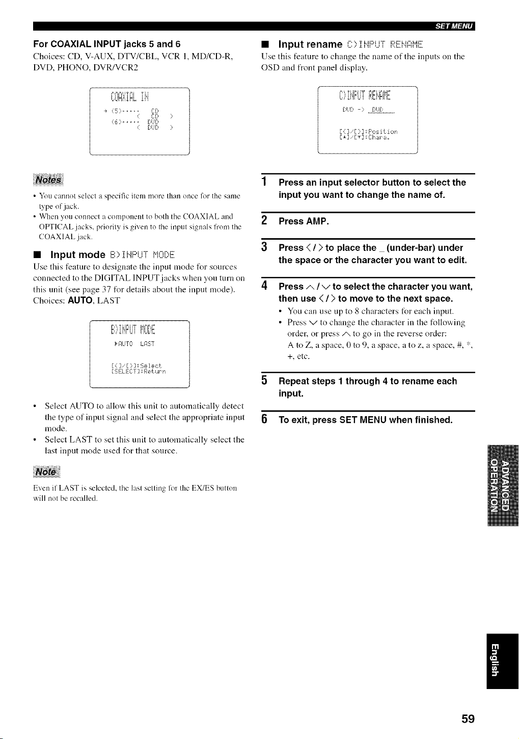
For COAXIAL INPUT jacks 5 and 6
Choices: CD, V-AUX, DTV/CBL, VCR 1, MD/CD-R,
DVD, PHONO, DVR/VCR2
l_llJrtl_h'r
• Input rename '', Ti..iJ:::,{i"i"J:::,i:::i..ii",i,,,ii:r
Use this feature to change tile name of the inputs on tile
OSD and front panel display.
L,LJff_"=_HL "i"i
÷ (5) ..... CD
C:D
(6) ..... DUD
DUD
[u[ -: =_.!::!,2._:".......
[ { ] [ ?] _F'os it lot,
• You cannot select a specific item more than once for the same
type of jack.
• When you connect a component to both the COAXIAL and
OFr['ICAL jacks, priority is given to the input signals from the
COAXIAL jack.
• Input mode B> II".IF:q..JTl'ql3E:,E
Use this feature to designate the input mode for sources
connected to the DIGITAL INPUT jacks when you turn on
this unit (see page 37 for details about the input mode).
Choices: AUTO, LAST
r",'_T _lr",lIT J,_,=,,=,=
c,,,'i{'ir t,u FiUL_L
_ _4LITO i_R'ST
[ i] [:::]_$elect
PEELECT] _Retu_ n
• Select AUTO to allow this unit to automatically detect
the type of input signal and select the appropriate input
mode.
• Select LAST to set this unit to automatically select the
last input mode used for that source.
1 Press an input selector button to select the
input you want to change the name of.
2 Press AMP.
3 Press ( / ) to place the _ (under-bar) under
the space or the character you want to edit.
4 Press/,, / v to select the character you want,
then use < / ) to move to the next space.
• You can use up to 8 characters t_r each input.
• Press v to change the character in the following
order, or press/x to go in the reverse order:
A to Z, a space, 0 to 9, a space, a to z, a space, #, *,
+, etc.
5 Repeat steps 1 through 4 to rename each
input.
To exit, press SET MENU when finished.
Even if LAST is selecled, the last selling for the EX/ES button
will nol be recalled.
59
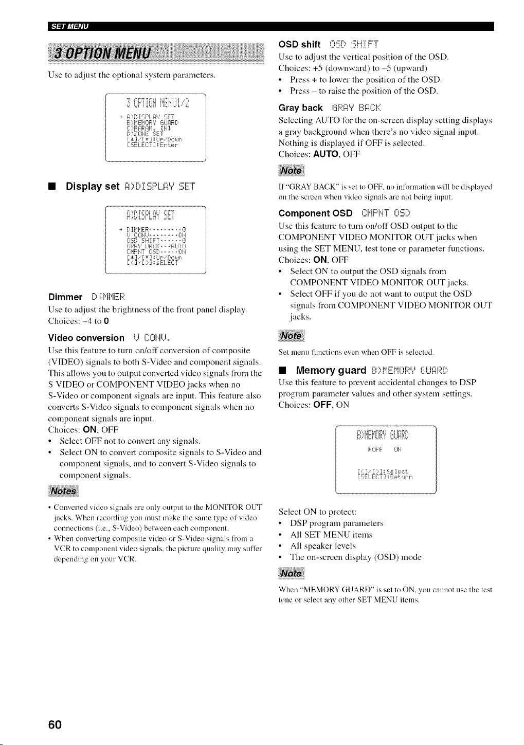
IFPlllJff_Ir
i! !! !
Use to adjust the optional system parameters.
n UFi'Ui'i i'Ci"iU'//,
A) Di £;F'LI:I', SE'/
F.,)I,IENOR'? GUARD
C:?F'AR@i,, iJqI
D)ZOHE SET
[ _] / [ _] I UP/Down
[ SELECT ] _En±er ¸¸
OSD shift 0!!!;[) :!!!;ii]] FT
Use to adjust the vertical position of the OSD.
Choices: +5 (downward) to -5 (upward)
• Press + to lower the position of the OSD.
• Press to raise the position of the OSD.
Gray back (!!iRA",'E:I:::I::K
Selecting AUTO for the on-screen display setting displays
a gray background when there's no video signal input.
Nothing is displayed if OFF is selected.
Choices: AUTO, OFF
• Display set ,-,,r, r,:::i:::,i,,,, ,::i:::r
'A' i'°,1'I _=,,,' ,=L i
DIHHER ......... iI
U CCIIqU........ 01£
Oq[,, SHIFT ..... '_
6RF# IF, El::=, =FlUTO
CHF'NT O::.D..... OH
[+] 'iv] I UF Douh
E : ] ::3 ;sELECT
Dimmer i%T MMi:::i:::,
Use to adjust the brightness of the front panel display.
Choices: -4 to 0
Video conversion i i ,=','%,iii
Use this feature to turn on/off conversion of composite
(VIDEO) signals to both S-Video and component signals.
This allows you to output converted video signals from the
S VIDEO or COMPONENT VIDEO.jacks when no
S-Video or component signals are input. This feature also
converts S-Video signals to component signals when no
component signals are input.
Choices: ON, OFF
• Select OFF not to convert any signals.
• Select ON to convert composite signals to S-Video and
component signals, and to convert S-Video signals to
component signals.
) \ ) (r
• C( n 'el'ted vide_ sienals are only output to Ihe MONITOR OUT
jacks. When recording you must make Ihe same lype ol video
connections (i.e., S-Video) belween each component.
• When converting composite video or S-Video signals from a
VCR to component video signals, the picture qualily may sutTer
depending on your VCR.
If "(;RAY BACK" is set to OFF. no information will be displayed
on the screen when video signals are not being input.
Component OSD C:MF:qqT0%,
Use this feature to turn on/off OSD output to the
COMPONENT VIDEO MONITOR OUT .jacks when
using the SET MENU, test tone or parameter functions.
Choices: ON, OFF
• Select ON to output the OSD signals from
COMPONENT VIDEO MONITOR OUT .jacks.
• Select OFF if you do not w,ant to output the OSD
signals from COMPONENT VIDEO MONITOR OUT
.jacks.
Set menu lunctions even when OFF is selected.
• Memory guard I!!!OMI!![M(:)F;?."?(!!iUI:::IRI,')
Use this feature to prevent accidental changes to DSP
program parameter values and other system settings.
Choices: OFF, ON
1 ,i i_ u i_,,
UiiiLi iJi'd
}OFF 314
[ (: ] [ : ] I 2;e1e,:t
[:£;ELEC:'/] Re{u_ n
Select ON to protect:
• DSP program parameters
• All SET MENU items
• All speaker levels
• The on-screen display (OSD) mode
When "MEMORY GUARD" is set to ON, you cannot use the lest
lone or select any other SET MENU items.
6O
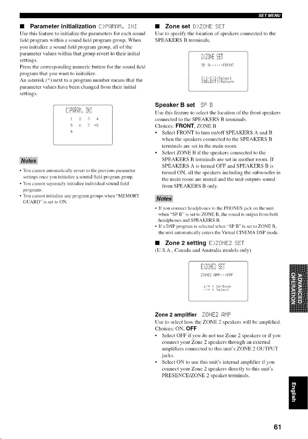
• Parameter initialization C)F'I:::i:;;:AM,,iHI
Use this feature to initialize the parameters for each sound
field program within a sound field program group. When
you initialize a sound field program group, all of the
parameter values within that group revert to their initial
settings.
Press the corresponding numeric button for the sound field
program that you want to initialize.
An asterisk (*) next to a program number means that the
parameter values have been changed from their initial
settings.
L,,qNffNi= ii'ii
I 2 3 4
5 {, ? *s
9
• You cannot automatically revert to the previous parameter
settings once you initialize a sound fiehl program group.
• You cannot separately initialize individual sound field
programs.
• You cannot initialize any program groups when "MEMORY
GUARD" is set to ON.
l=lllJ,_l_l,i,
• Zone set [:,);i:=Oii![SET
Use to specify the location of speakers connected to the
SPEAKERS B terminals.
B,% ,m'F _=FT
i.,',=?_]i'L:-i
SF' B ...... F ROIIT
[ : ] [ )] ISelect
[ {,ELECT] Retuth
Speaker B set Si:::'B
Use this feature to select the location of the front speakers
connected to the SPEAKERS B terminals.
Choices: FRONT, ZONE B
• Select FRONT to turn on/off SPEAKERS A and B
when the speakers connected to the SPEAKERS B
terminals are set in the main room.
• Select ZONE B if the speakers connected to the
SPEAKERS B terminals are set in another room. If
SPEAKERS A is turned OFF and SPEAKERS B is
turned ON, all the speakers including the snbwoofer in
the main room are muted and the unit outputs sound
from SPEAKERS B only.
• If you connect headphones to the PHONES jack on the unit
when "SP B" is set to ZONE B, the sound is output l_'om both
headphones and SPEAKERS B.
• If a DSP program is selected when "SP B" is set to ZONE B,
the unit automaticNly enters the Virtual CINEMA DSP mode.
• Zone 2 setting i:::v::,,-,i..:::.:, ,::n:::°r'L,...'=:-,..u ".%...a:.....,I.... 1
(U.S.A., Canada and Australia models only)
F ',,=h% IF ,= :=FT
C,,,a=,,E,.;2{ i
1101112 If'IF',, ,0FF
_ v I Lll /[:,oMn
- i I L,,,'I_K'I
Zone 2 amplifier "2f",Mi::D":,,",i','ii:::,
Use to select how the ZONE 2 speakers will be amplified.
Choices: ON, OFF
• Select OFF if you do not use Zone 2 speakers or if you
connect your Zone 2 speakers through an external
amplifiers connected to this unit's ZONE 2 OUTPUT
jacks.
• Select ON to use this unit's internal amplifier if you
connect your Zone 2 speakers directly to this unit's
PRESENCE/ZONE 2 speaker terminals.
61
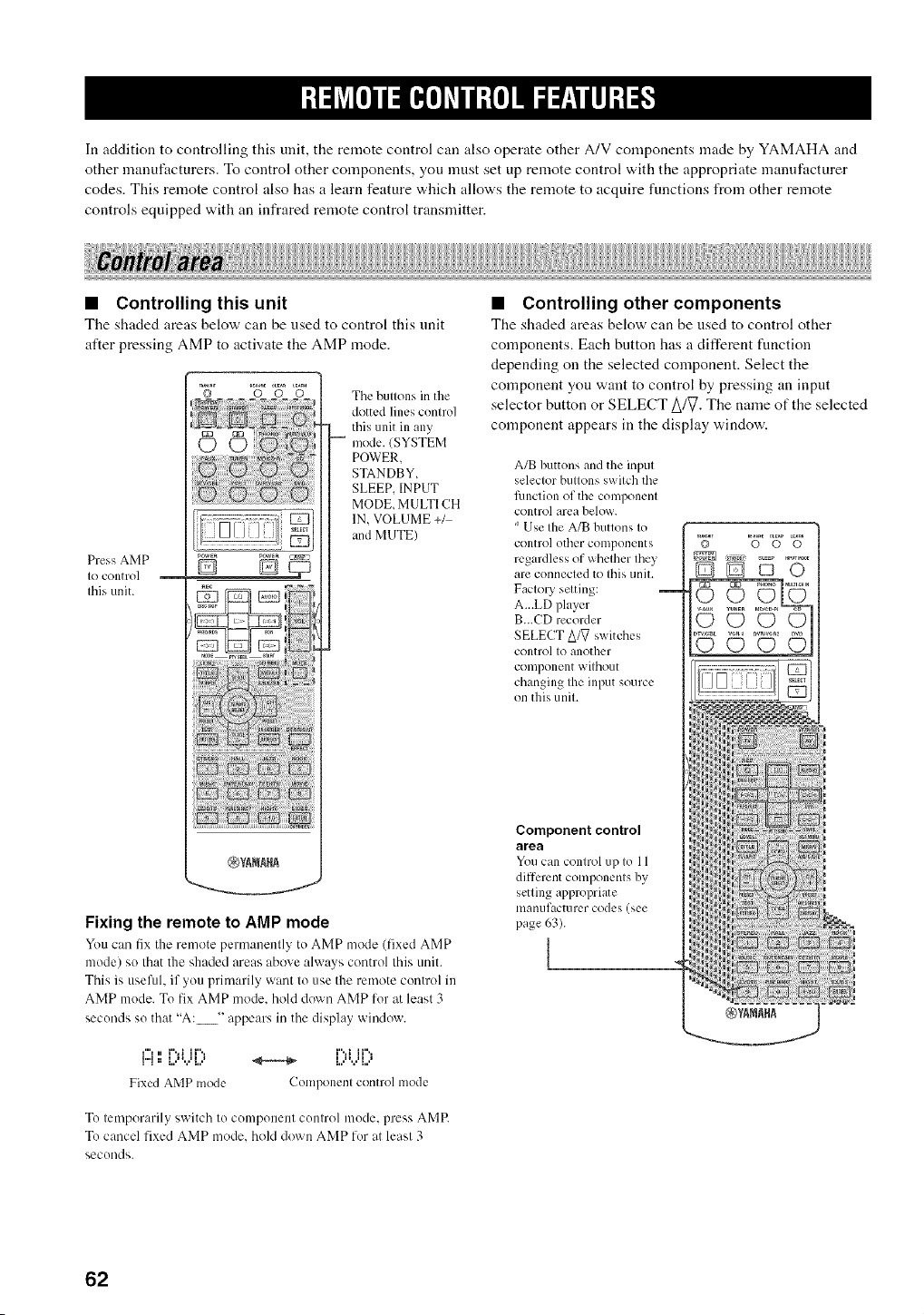
In addition to controlling this unit, the remote control can also operate other A/V components made by YAMAHA and
other manufacturers. To control other components, you must set up remote control with the appropriate manufacturer
codes. This remote control also has a learn feature which allows the remote to acquire functions from other remote
controls equipped with an infrared remote control transmitter.
• Controlling this unit
The shaded areas below can be used to control this unit
after pressing AMP to activate the AMP mode.
Press AMP
IO control
Ihis unit.
D DcT_
Tile buttons in the
dotted lines control
this unit in any
mode. (SYSTEM
POWER.
STANDBY,
SLEEP. INPUT
MODE, MULTI CH
IN, VOLUME +/
and MUTE)
Fixing the remote to AMP mode
Yo/I can i]x the remote perm:mently to AMP mode (fixed AMP
mode) so that the shaded areas above always control this unit.
This is useful, if you primarily want to use the remote control in
AMP mode. To fix AMP mode. hold down AMP lor at least 3
seconds so that "A: "' appears in the display window.
f"l n i%1 11'% i",,i 11'%
h,a. t H H _ _ i H H
Fixed AMP mode Componenl control mode
• Controlling other components
The shaded areas below can be used to control other
components. Each button has a different function
depending on the selected component. Select the
component you want to control by pressing an inpnt
selector button or SELECT A/_. The mane of the selected
component appears in the display window.
A/B buttons and the input
selector buttons switch the
fimction of the component
control area below.
Use the A/B buttons to
control other components
regardless of whether they
arc connected to this unit.
Factory setting:
A...LD player
B...CD recorder
SELECT Aft7 switches
control to another
component without
changing the input source
on this unit.
Component control
area
You can control up to 11
different components by
setting appropriate
man/if;wturer codes (see
page 63).
J
© 0 0 0
IDQQO
............ b
i i
N
i .....
a_ a
@,_ANA_A
To temporarily switch Io componenl control mode, press AMR
To cancel fixed AMP mode, hold down AMP for at least 3
seconds.
62
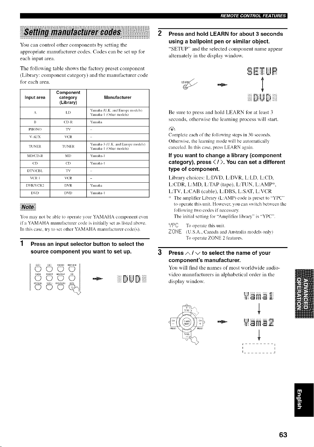
;/:h_[o]l:ll,[o]dlll{o]J._.___|ll]:/:[,
You can control other components by setting the
appropriate manufacturer codes. Codes can be set np for
each input area.
The following table shows the factory preset component
(Library: component category) and the manufactnrer code
for each area.
Component
Input area category Manufacturer
(Library)
A I,I) Yamaha (VK and Europe m(xkqsi
Yamaha 1 (OIhel models/
I3 ('I) R Yamaha
PHONO TV
VAUN VCR
TIINI R TUNIR Yamaha 3 (I!K and Lurope moddsi
Yamaha 1 (OIhvl models)
MI)/CI) R MI) Yamaha 1
CI) {'I) Yamaha 1
I)TV/L'BI, TV
VCR I VL'R
I)VI*2FVL'R2 I)VR Yamaha
I)VI) I)VI) YamaIH 1
You may not be able I1) operate your YAMAHA component even
if a YAMAHA manufacturer code is initially set as listed above.
In Ihis case, Iry to sel olher YAMAHA manulaclurer code(s).
1 Press an input selector button to select the
source component you want to set up.
©°U
..........'2i ......
Press and hold LEARN for about 3 seconds
using a ballpoint pen or similar object.
"SETUP" and the selected component name appear
alternately in the display window.
1% I I ,_,
Be sure to press and hold LEARN for at least 3
seconds, otherwise the learning process will start.
"4¢--
Complete each of the li}llowing steps in 30 seconds.
Olherwise. Ihe learning mode will be automatically
canceled. In Ibis case. press LEARN again.
If you want to change a library (component
category), press ( / ). You can set a different
type of component.
Library choices: L:DVD, L:DVR, L:LD, L:CD,
L:CDR, L:MD, L:TAP (tape), L:TUN, L:AMP*,
L:TV, L:CAB (cable), L:DBS, L:SAT, L:VCR
':' The amplifier Library (L:AMP) code is preset to "YPC"
to operate Ihis allit. However, 5,/)11can switch between Ihe
following [\_rocodes if necessary.
The initial setting lor "Amplifier library" is "YPC".
UID f"
] ,.... To operate this unil.
,::'£UbH:::.(U.S.A.. Canada and Australia models only)
To operate ZONE 2 lealures.
Press/,, / -,/to select the name of your
component's manufacturer.
Yon will find the names of most world'Mde audio-
vMeo manufactnrers in alphabetical order in the
display window.
_aa]mH_m
i I
I I
I 1
63
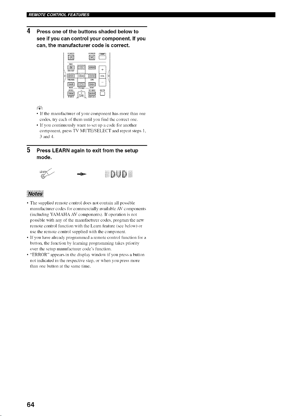
|:I:[j_[O]I:II,[O]_TII:{O]J._.___|II]:I._
Press one of the buttons shaded below to
see if you can control your component. If you
can, the manufacturer code is correct.
pow_n PaWER
i)........ ..............
LEVEL A S_T_U _UTE
• |f the Illanuilictm_er of yo/lr coll]poneot h_ls more [h{m one
codes, try each of thmn until you lind the correct one.
• If you continuously want to set up a code for another
component, press TV MUTE/SELECT and repeat steps I.
3 and 4.
5 Press LEARN again to exit from the setup
mode.
"_ i!ii L_iJ Di !iii
• The supplied remote control does not contain all possible
manufacturer codes for commercially m ailable AV components
(including YAMAHA AV components). If operation is not
possible with any of the manufacturer codes, program the new
remote control fimction with the Learn lcature (see below) or
use the remote control supplied with the componmlt.
• If you have already programmed a remote control flmction I7_ra
button, the lhnction by learning programming takes priority
over the setup mallufacturcr code's [llnctio[/.
• "ERROR" appears in the display window if you press a button
not indicated in the respective step, or when you press more
than one button at the same time.
64
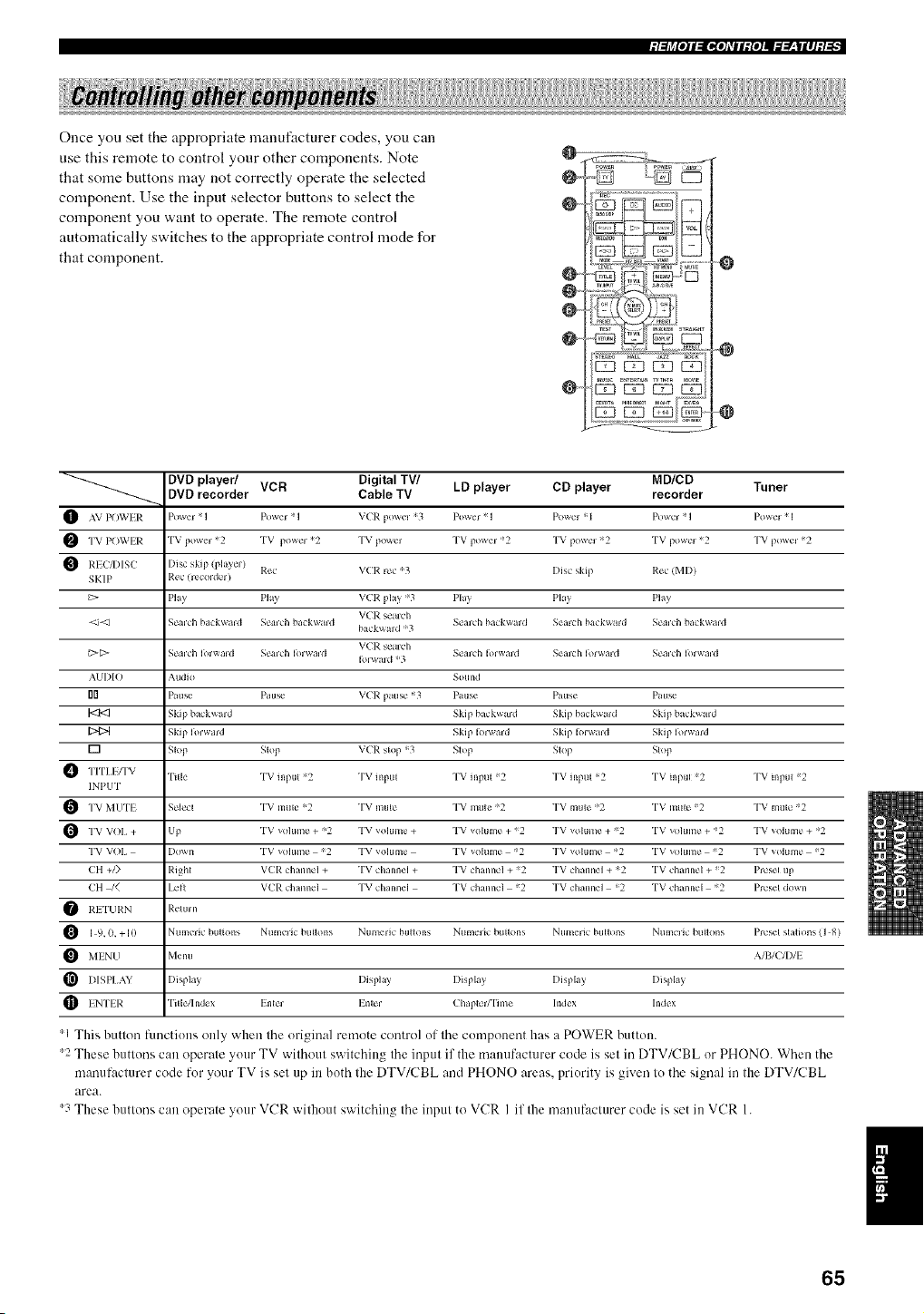
;I:[j_[O]I:II,[O]_TII:{O]J._ff__|II]:I:[,
Once you set the appropriate manufacturer codes, you can
use this remote to control your other components. Note
that some buttons may not correctly operate the selected
component. Use the input selector buttons to select the
component you want to operate. The remote control
automatically switches to the appropriate control mode for
that component.
O--
@
O_
Oo
O
"0
-@
DVD player/ VCR Digital TV/ LD player CD player MD/CD TunerDVD recorder Cable TV recorder
O Power 1 Power ! I V(P. ;3 Po\_er ! I Po_'l =`1 Powcl ! I Powcl ! I
F_ T POWER
TV *2 TV *2 TV TV *2 TV *2 TV *2 "['V *2
POWlR
power powel po_er powel powcl
1_ P.c,c VCR rc_ '3 Disc sklp F:c_ (MDI
REC_)ISC I)i_c
skip pla\el
SKIP I,{cc (recoldcl I
C> Pla_ Ph_ V(R pla)"3 Pla) Pkl_ Pla)
VCR sealdl
<_-d S_'mh ba k\_ald S_'mh ba kwald S_'mh ba k_ tld Semh bt_k_ard S_'mh ba kwald
ha( k_ aid ='3
VCR seaich
_[;> S_" m'h I )l_ald S_'mh I )lwald S_" m'h I )1_ rid Sen h Ior_ trd S_'aldl I _l_ald
Ib_ t_d ;3
AUI)IO Audio Sound
rlrl Patl_" Pau_" V(R patl_" =3 Pa us_" Ptusc Pau_"
1<3<3 Skip bl kward Skip hi kward Skip ha kwa=d Skip hl_kwmd
Skip Iorward Skip I >_ward Skip I !lwa=d Skip Iorward
[] Slop Slop V(P. skip =_3 S_op Slop Slop
Ti[le TV inpul 2 TV input TV input 2 TV input =2 TV inpu_ 2 TV inpul 2
INPUT
"I'V MUTI S_qc_ TV mute =;2 TV muk" TV mule ;2 TV muk" =;2 TV mule 2 TV mute 2
TV _<)lum_" _2 TV vohlme TV vohlmc _2 TV vohlme 2 TV _olum_" _2 TV _olum_" _2VOI, Up+
+ + + + + +
TV VOI, I)ox_ n TV _olum_" 2 TV vohlme TV _ohlmc 2 TV vohlmc _2 TV _<>lum_" 2 TV _olum_" 2
CH +/) Righl VCI_: ch mncl + TV _hannel + TV ch inncl + 2 TV _hannel + =_2 TV d_ inn_'l + _2 Prcs_q up
CH /_ I,cil VL'p.d_ann_,l TVchannel "I'Vd_mn_,l 2 TVchannel _2 "I'Vd_lnn_,l =2 Prcs_qdown
I_.I "I'LII_:N Rclu= n
Ntlmelic bul_olls Ntlmelic btlllo_ls Numeric btlllo_ls Ntlmelic bullo_ls Numeric btlllons Nt_melic btlllo_ls Presel sl;tlJons ] 8
I
9,
0. +10 ( )
Menu AIBICII)II
MINU
I[_ I)ISPI,AY I)ispla} I)ispht_ I)ispla_ I)ispht} I)ispla_
ENTI I_: "l'itle/hld_ x Inle_ Inle_ ChapleW'l'i m_ hldex hMex
1 This button ffmctiuns only when the original remote control uf the component has a POWER button.
2 These buttons can operate yuur TV without switching the input if the mamff:lcturer code is set in DTV/CBL or PHONO. When the
manuf:_cturer code for your TV is set up in both the DTV/CBL and PHONO areas, priurity is given tu the signal in the DTV/CBL
area.
'3 These buttons can operate your VCR without switching the input to VCR I if the mamff:_cturer code is set in VCR 1.
I
65
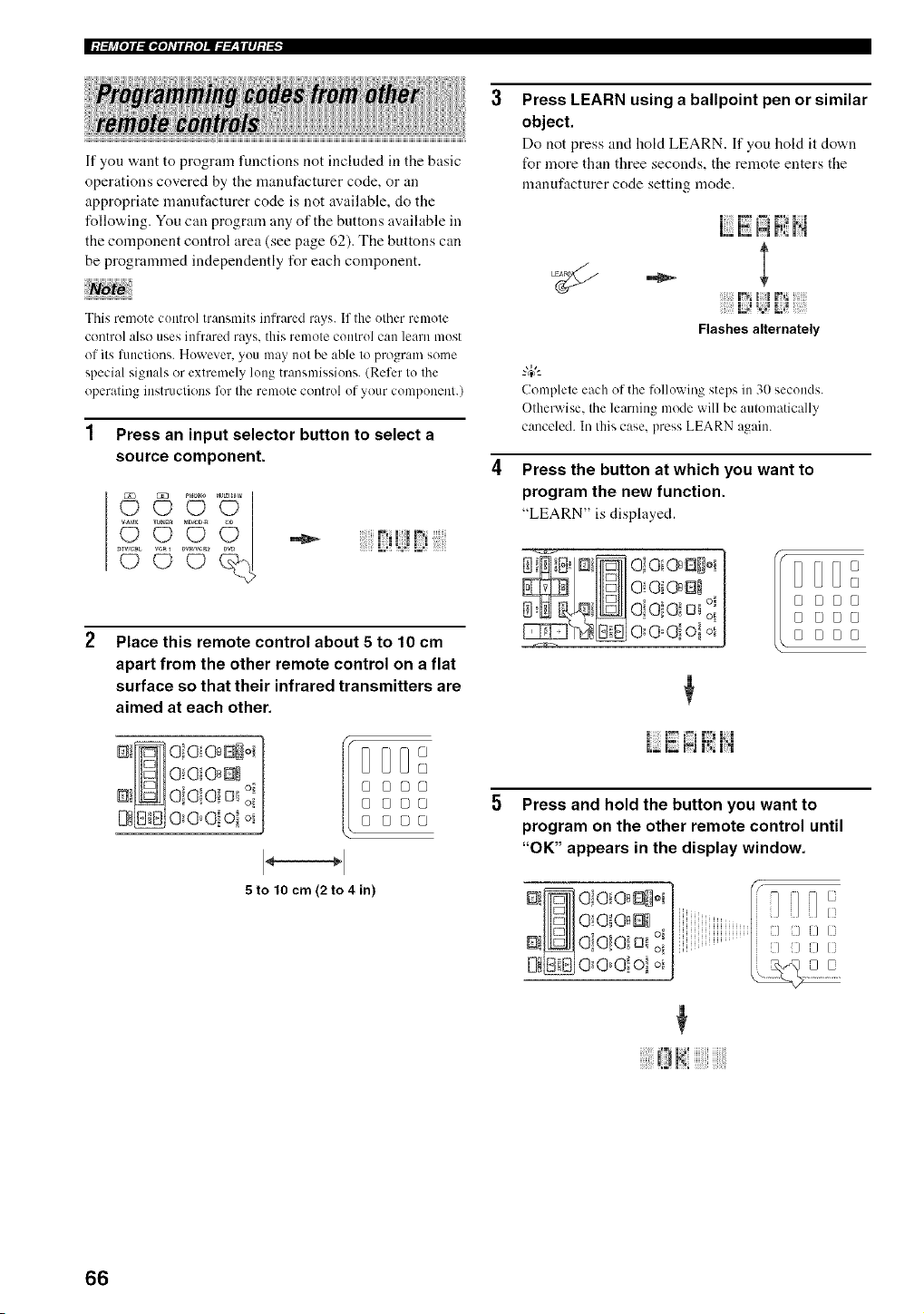
|:/:[j_[o]l:ll,[oATil:{o]Jffff__|ll]:/._
If you want to program functions not included in the basic
operations covered by the manufacturer code, or an
appropriate manufacturer code is not available, do the
following. You can program any of the buttons available in
the component control area (see page 62). The buttons can
be programmed independently for each component.
This rmnote control transnlits infrared rays. If the other remote
control also uses infrared rays. this remote control can learn most
of its limctions. However. you may not be able to program sonm
special signals or extrenmly long transmissions. (Refer to the
operating instructions for the remote control of your component.)
1 Press an input selector button to select a
source component.
Place this remote control about 5 to 10 cm
apart from the other remote control on a flat
surface so that their infrared transmitters are
aimed at each other.
@
DD@[]
[] [][][]
[] [][][]
[] _[][]
5to tO cm (2 to 4 in)
Press LEARN using a ballpoint pen or similar
object.
Do not press and hold LEARN. If you hold it down
for more than three seconds, the remote enters the
manufacturer code setting mode.
i i',_IJ N i_
- l
l!i F_
Flashes alternately
Complete each of the lollowing steps in 31)seconds.
Otherwise. the learning mode will be automatically
canceled. In this case. press LEARN again.
Press the button at which you want to
program the new function.
"LEARN" is displayed.
O!Oi @ E]_
O_O Oi Oi oi
00@0! ol o_
DDD
[]
Fs FSD•
DE}DE}
_ __8
Press and hold the button you want to
program on the other remote control until
"OK" appears in the display window.
7]i/i1/
[XXi
i/ iXXliNK/(3
iiiiiiiii!Uiii0 J_!!JJJJiii!iiiii!!iiii!!
66
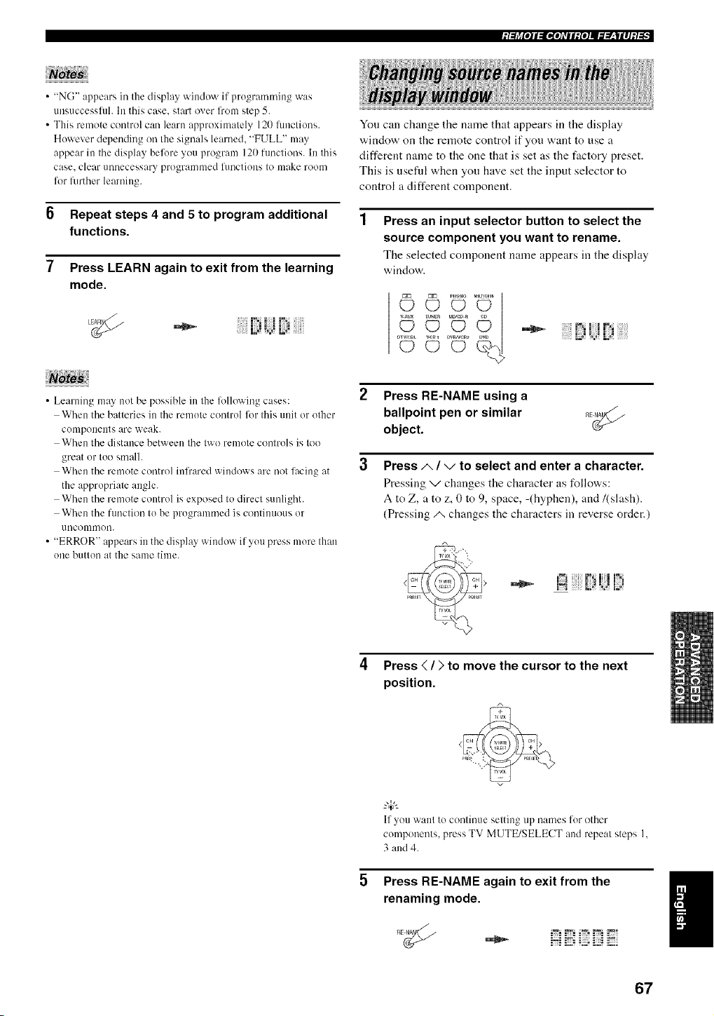
;/:[l_[I]l:ll,[I]_lll:{I]J._.___|ll]:/:[,
• "NG" appears in the display window if programming was
/lllS[Iccessltll. In this case, start over fronl step 5.
• This remote control can learn approximately 120 fnnclions.
However depending on tile signals learned. "FULL" may
appear in Ihe display before you progranl 120 functions. In Ihis
case. clear unnecessary programmed lunctions to make room
for further learning.
6 Repeat steps 4 and 5 to program additional
functions.
7 Press LEARN again to exit from the learning
mode.
•_ iJ id L;i
• Learning may not be possible in the %llowing cases:
When the batteries in the remote control for this unit or other
components are weak.
When the distance between the two remote controls is too
great or too smalh
When the remote control infrared windows are not lacing at
the appropriate angle.
When the remote control is exposed to direct sunlight.
When the function to be programmed is continuous or
uncommon.
• "ERROR" appears in the display window if you press more than
one button at the same time.
Yon can change the name that appears in the display
window on the remote control if you want to use a
different name to the one that is set as the ti_ctory preset.
This is useftd when yon have set the input selector to
control a different component.
Press an input selector button to select the
source component you want to rename.
The selected component name appears in the display
window.
i._ ¸ _ _ _i
2 Press RE-NAME using a
ballpoint pen or similar
object.
Press/,, / v to select and enter a character.
Pressing v changes the character as follows:
A to Z, a to z, 0 to 9, space, -(hyphen), and/(slash).
(Pressing/_ changes the characters in reverse order.)
i;i f !J!i
4 Press < / > to move the cursor to the next
position.
If you want to continue setting up names for other
components, press TV MUTE/SELECT and repeat steps I,
3 and 4.
Press RE-NAME again to exit from the
renaming mode.
67
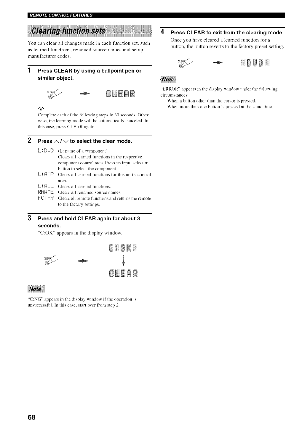
|:l:[j_[o]l:ll,[o]_rll:{o]J._.___|ll]:l._
You can clear all changes made in each flmction set, such
as learned functions, renamed source names and setup
manut_lcturer codes.
Press CLEAR by using a ballpoint pen or
similar object.
Complete each uf the following steps in 30 seconds. Other
wise, the learning mode will be autumatically canceled. In
this case, press CLEAR again.
Press/', / -,/to select the clear mode.
i • r'.,i ii%
i • _",h'iiD
i..,=, i"ii ii
i • _"li i
La i.._ H','H...
V'A _r"H H.-
i... i • i _...,,.._
(L: name of a component)
Clears all learned flmctions in the respective
compouent coutrul area. Press au iupnt selector
button tu select the cumponent.
Clears all learned functious lor this unit's control
area.
Clears all learned flmctions.
Clears all renamed suurce names.
Clears all remote flmctions and returns the remote
to the lhctory settings.
3 Press and hold CLEAR again for about 3
seconds.
"C:OK" appears in the display window.
i_i_ ij!_: !!!iiiii!'i,ill
{',! E !;!
"C:NG" appears in the display winduw if the uperatiun is
uusuccessfuh In this case. slarl uver from step 2.
Press CLEAR to exit from the clearing mode.
Once you have cleared a learned flmction for a
button, the button reverts to the factory preset setting.
....i ,?
i;i;i;ij;iiiiF:iUtiiiiiiiiiii
"ERROR" appears in the display winduw under the lbllowiug
circumstances:
When a buttun other than the cursor is pressed.
When more than one button is pressed at the same time.
68
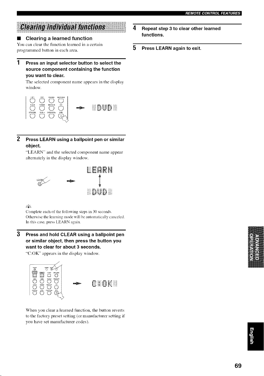
;I:[j_[O]I:II,[O]_TII:{O]J._.___|II]:I:[,
4 Repeat step 3 to clear other learned
functions.
5 Press LEARN again to exit.
• Clearing a learned function
You can clear tile function learned in a certain
programmed button in each area.
1
Press an input selector button to select the
source component containing the function
you want to clear.
Tile selected component name appears in the display
window.
°U© °U
Press LEARN using a ballpoint pen or similar
object.
"LEARN" and the selected component name appear
alternately in the display window.
|:","|
Complete each of the %llowing steps in 30 seconds.
Otherwise the learning mode will be automatically canceled.
In this case, press LEARN again.
Press and hold CLEAR using a ballpoint pen
or similar object, then press the button you
want to clear for about 3 seconds.
"C:OK" appears in the disphty "a,indo'a,.
L; i3 ._a!:i
When you clear a learned function, the button reverts
to the factory preset setting (or manufacturer setting if
you have set manufacturer codes).
I
69
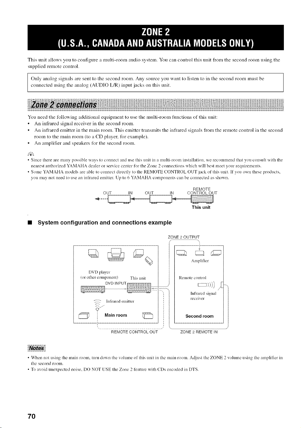
This unit allows you to configure a multi-room audio system. You can control this unit from the second room using the
supplied remote control.
Only analog signals are sent to the second room. Any source you want to listen to in the second room must be
connected using the analog (AUDIO L/R) input jacks on this unit.
You need the following additional equipment to use the multi-room fimctions of this unit:
• An infrared signal receiver in the second room.
• An infrared emitter in the main room. This emitter transmits the infrared signals from the remote control in the second
room to the main room (to a CD player, for example).
• An anaplifier and speakers t_r the second room.
• Since there are many possible ways to connect and use this unit in a multi-room installation, we recommend that you consult with the
nearest authorized YAMAHA dealer or service center for the Zone 2 counectkms which will best meet your requirements.
• Some YAMAHA models are able to connect directly to the REMOTE CONTROL OUT ,_ck of this unit. If you own these products,
you may not need to use an infrared emitter. Up to 6 YAMAHA components can be connected as shown.
REMOTE
OUT IN OUT IN CONTROL OUT
This unit
• System configuration and connections example
DVD player
(or other component) This unil
Infrared elnitler
Main room
REMOTECONTROLOUT
ZONE2OUTPUT
Amplifier
Remote control
hffraled signal
receiver
Second room
ZONE 2 REMOTE IN
• When not using the main room. turn down the volume ol this unit in the main room. A@dsl the ZONE 2 volume using the amplifier in
the second rOOI][I.
• To avoid unexpected noise. DO NOT USE lhe Zone 2 feature with CDs encoded in DTS.
7O
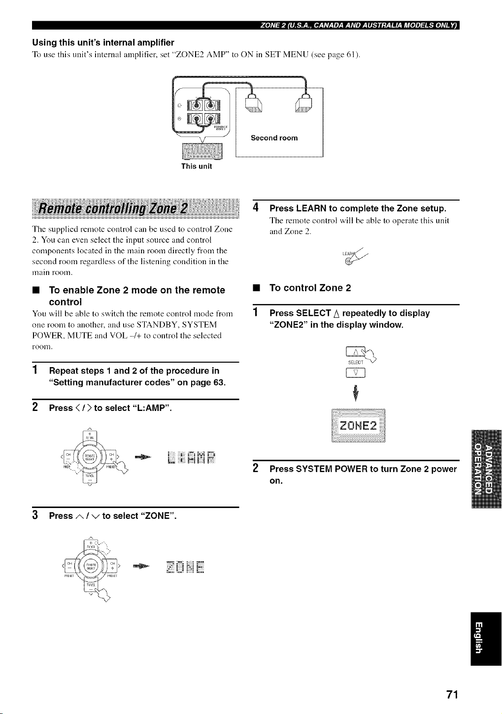
Using this unit's internal amplifier
To use this unit's internal amplifier, set "ZONE2 AMP" to ON in SET MENU (see page (,l).
ondroom
This unit
The supplied remote control can be used to control Zone
2. You can even select the input sonrce and control
components located in the main room directly from the
second room regardless of the listening condition in the
lnain room.
• To enable Zone 2 mode on the remote •
control
You v,,ill be able to switch the remote control mode from 1
one room to another, and use STANDBY, SYSTEM
POWER, MUTE and VOL -1+ to control the selected
roon].
1 Repeat steps 1 and 2 of the procedure in
"Setting manufacturer codes" on page 63.
2 Press </) to select "L:AMP'.
Press LEARN to complete the Zone setup.
The remote control will be able to operate this unit
and Zone 2.
To control Zone 2
Press SELECT A repeatedly to display
"ZONE2" in the display window.
L_ m_l m;;:l1;
Press SYSTEM POWER to turn Zone 2 power
on.
3 Press/,, / ",/to select "ZONE".
71
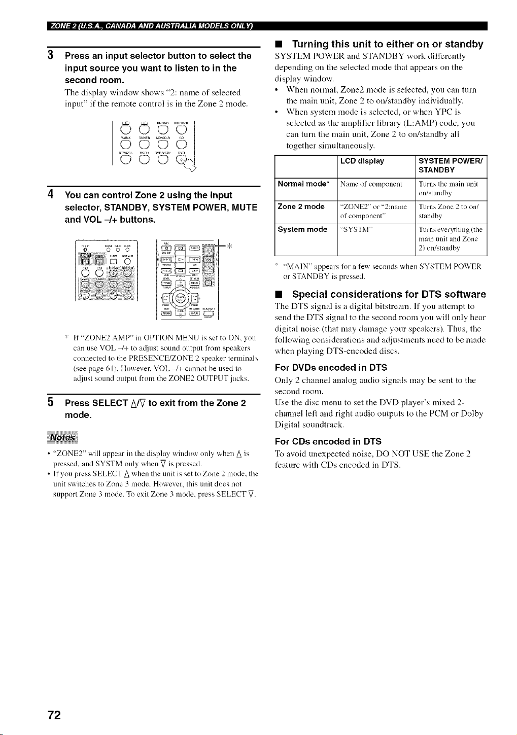
P_e],V:J,Jl#l_:_:l,vV:leT:7:Y,VpJr:l#_l;Y:YlrJi_fe]p]_e],Vl_
Press an input selector button to select the
input source you want to listen to in the
second room.
Tile disphty window shows "2: name of selected
inpnt" if the remote control is in the Zone 2 mode.
DVRN_
©
You can control Zone 2 using the input
selector, STANDBY, SYSTEM POWER, MUTE
and VOL -/+ buttons.
':' If "ZONE2 AMP" in OPTION MENU is set to ON, you
can use VOL _+ to a;liust sound output from speakers
commcted to the PRESENCE/ZONE 2 speaker terminals
(see page 61). However. VOL _+ cmmot be used to
atljust sound output h'om the ZONE2 OUTPUT jacks.
Press SELECT A/V to exit from the Zone 2
mode.
• "ZONE2" will @pear in the display window only when A is
pressed, and SYSTM only when V is pressed.
• If you press SELECT A when the unit is set to Zone 2 mode. the
unit switches to Zone 3 ]node. However. this unit does not
support Zone 3 mode. To exit Zone 3 mode, press SELECT V.
• Turning this unit to either on or standby
SYSTEM POWER and STANDBY work differently
depending on the selected mode that appears on the
display window.
• When normal, Zone2 mode is selected, you can tnrn
the main unit, Zone 2 to on/standby individually.
• When system mode is selected, or when YPC is
selected as the amplifier library (L:AMP) code, you
can turn the main unit, Zone 2 to on/standby all
together simnltaneonsly.
LeD display SYSTEM POWER/
STANDBY
Normal mode* Name of component Turns the main unit
on/standby
Zone 2 mode "ZONE2" or "2:name Turns Zone 2 to on/
of component" standby
System mode "SYSTM" Turns everything (the
main unit and Zone
2) on/standby
"MAIN" appears %r a llewseconds when SYSTEM POWER
or STANDBY is pressed.
• Special considerations for DTS software
The DTS signal is a digital bitstream. If you attempt to
send the DTS signal to the second room yon will only hear
digital noise (that may damage your speakers). Thus, the
t%llowingconsiderations and adjustments need to he made
when playing DTS-encoded discs.
For DVDs encoded in DTS
Only 2 channel analog audio signals may be sent to the
second roonl,
Use the disc menu to set the DVD player's mixed 2-
channel left and right audio outputs to the PCM or Dolby
Digital sonndtrack.
For CDs encoded in DTS
To avoid unexpected noise, DO NOT USE the Zone 2
feature with CDs encoded in DTS.
72
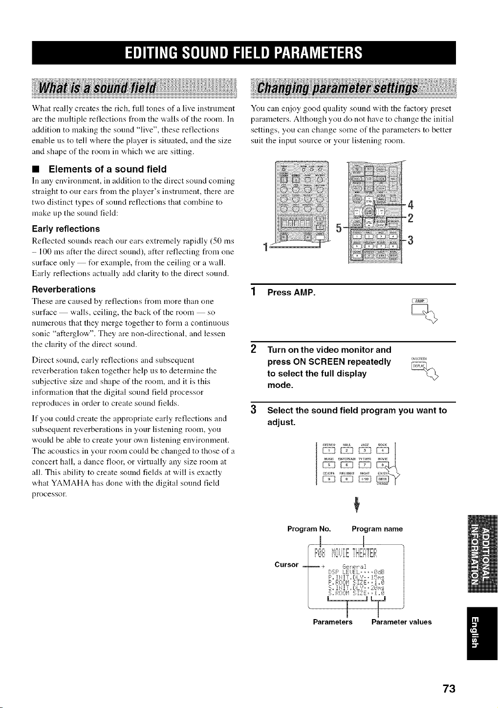
What really creates the rich, full tones of a live instrument
are the multiple reflections from the walls of the room. In
addition to making the sound "live", these reflections
enable us to tell where the player is situated, and the size
and shape of the room in which we are sitting.
Yon can enjoy good quality sound with the factory preset
parameters. Although you do not have to change the initial
settings, you can change some of the parameters to better
suit the input source or your listening room.
• Elements of a sound field
In any environment, in addition to the direct sound coming
straight to our ears from the player's instrument, there are
two distinct types of sound reflections that combine to
make up the sound field:
Early reflections
Reflected sounds reach our ears extremely rapidly (50 ms
- 100 ms after the direct sound), alter reflecting from one 1
surface only for example, from the ceiling or a wall.
Early reflections actually add clarity to the direct sound.
Reverberations
These are caused by reflections from more than one
surface walls, ceiling, the back of the room so
numerous that they merge together to form a continuous
sonic "afterglow". They are non-directional, and lessen
the clarity of the direct sound.
Direct sound, early reflections and subsequent
reverberation taken together help us to determine the
subjective size and shape of the room, and it is this
information that the digital sound field processor
reproduces in order to create sound fields.
3
If you could create the appropriate early reflections and
subsequent reverberations in your listening room, you
woukt be able to create your own listening environment.
The acoustics in your room could be changed to those of a
concert hall, a dance floor, or virtually any size room at
all. This ability to create sound fields at will is exactly
what YAMAHA has done with the digital sound fiekt
processor.
5-
......
4
-2
-3
1 Press AMP.
Turn on the video monitor and
press ON SCREEN repeatedly ........
to select the full display
mode.
Select the sound field program you want to
adjust.
_i _ __uvs_ EmERT_n TWHm _aOWE
a_ts P_nEDI_E__HT
Program No. Program name
m
D'_O iiLk.liE.',N_H{_.
Cursor _ .÷ Ge_,,__,1
E:,::.F'LEiJEL, _, ,CI,dB
F',,iHIT_I)L',',, !Si,_:_
F'. ROOIq 5; ZZ E), 1 ,,0
5,, !i4!T,, [:,L','= =2€_h:
5., F,:!;nH SIZE;,, i ,,_71
Parameters Parameter values
I
73
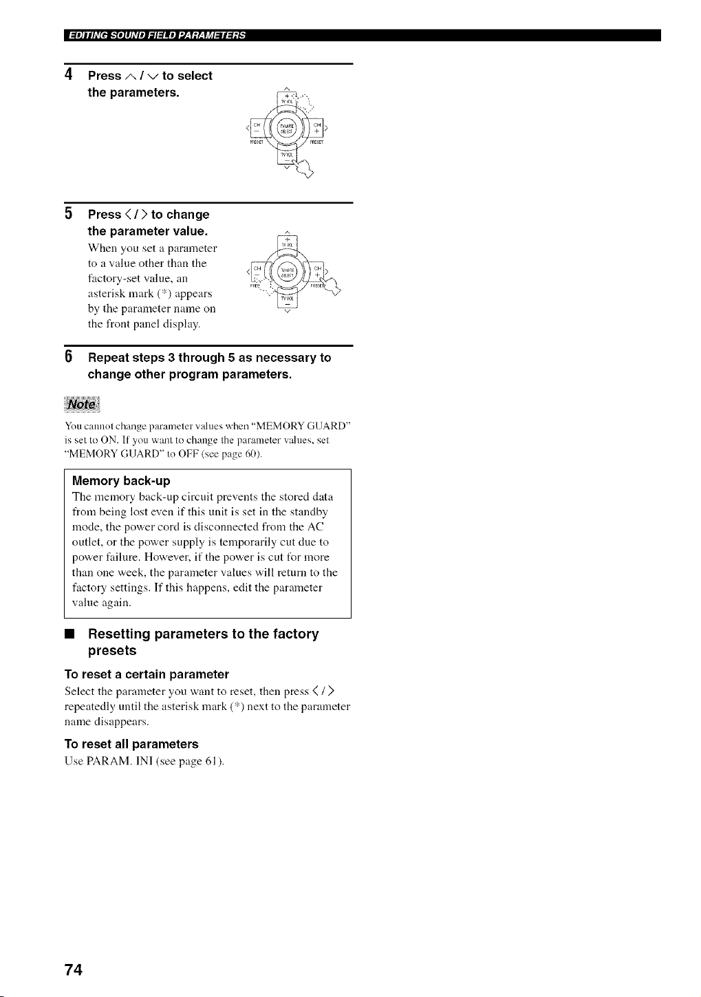
IW_le]ilhV[eff_e]lhVplT, l_llel'J__f:L_li_l_l_l_.f "
4 Press A / v to select
the parameters.
Press < / > to change
the parameter value.
When you set a parameter
to a value other than the
factory-set value, an
asterisk mark (*) appears
by the parameter name on
the front panel display.
Repeat steps 3 through 5 as necessary to
change other program parameters.
You cannot change parameter values when "MEMORY GUARD"
is set to ON. If you want to change the parameter wdues, set
"MEMORY GUARD" to OFF (see page 60).
Memory back-up
The memory back-up circuit prevents the stored data
from being lost even if this unit is set in the standby
mode, the power cord is disconnected from the AC
outlet, or the power supply is temporarily cut clue to
power fidlure. However, if the power is cut tUr more
than one week, the parameter values will return to the
factory settings. If this happens, edit the parameter
value again.
• Resetting parameters to the factory
presets
To reset a certain parameter
Select the parameter you want to reset, then press <(/ )
repeatedly until the asterisk mark (*) next to the parameter
name disappears.
To reset all parameters
Use PARAM. IN] (see page 61).
74
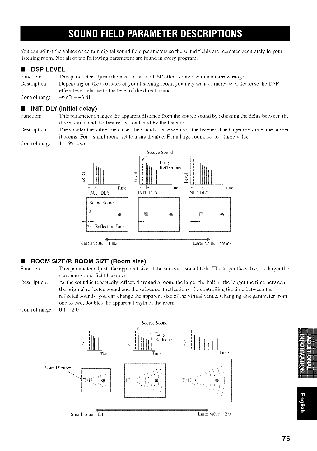
You can adiust the values of certain digital sound field parameters so the sound fields are recreated accurately in your
listening room. Not all of the following parameters are found in every program.
• DSP LEVEL
Function: This parameter adjusts the level of all the DSP effect sounds v,,ithin a Ilarrow range.
Description: Depending on the acoustics of your listening room, you may want to increase or decrease the DSP
effect level relative to the level of the direct sound.
Control range: 6 dB +3 dB
• INIT. DLY
Function:
Description:
Control range:
(Initial delay)
This parameter changes the apparent distance from the source sound by adjusting the dehty between the
direct sound and the first reflection heard by the listener.
The smaller the value, the closer the sound source seems to the listener. The larger the value, the farther
it seems. For a small room, set to a small value. For a large room, set to a large value.
1 - 99 msec
I
I
_1_" Tilne
INIT.DLY
[ SoundSource
[_ ReflectionFace
Source SOulld
f
-- Early
II Refleclions
i
_1-._ Time
INIT.DLY
<_ -_
Small value= I ms Largevalue= 99 ms
• ROOM SIZE/R ROOM SIZE (Room size)
Function: This parameter adjusts the apparent size of the surround sound field. The larger the value, the larger the
surround sound field becomes.
Description: As the sound is repeatedly reflected around a room, the larger the hall is, the longer the time between
the original reflected sound and the subsequent reflections. By controlling the time between the
reflected sounds, you can change the apparent size of the virtual venue. Changing this paraineter from
one to two, doubles the apparent length of the room.
0.1 2.0
Control range:
SourceSound
,/
Early
Reflections
I
,-a
Time Time Time
Sound _ Otl lce
Smallvalue= 0.1 Large value = 2.()
75
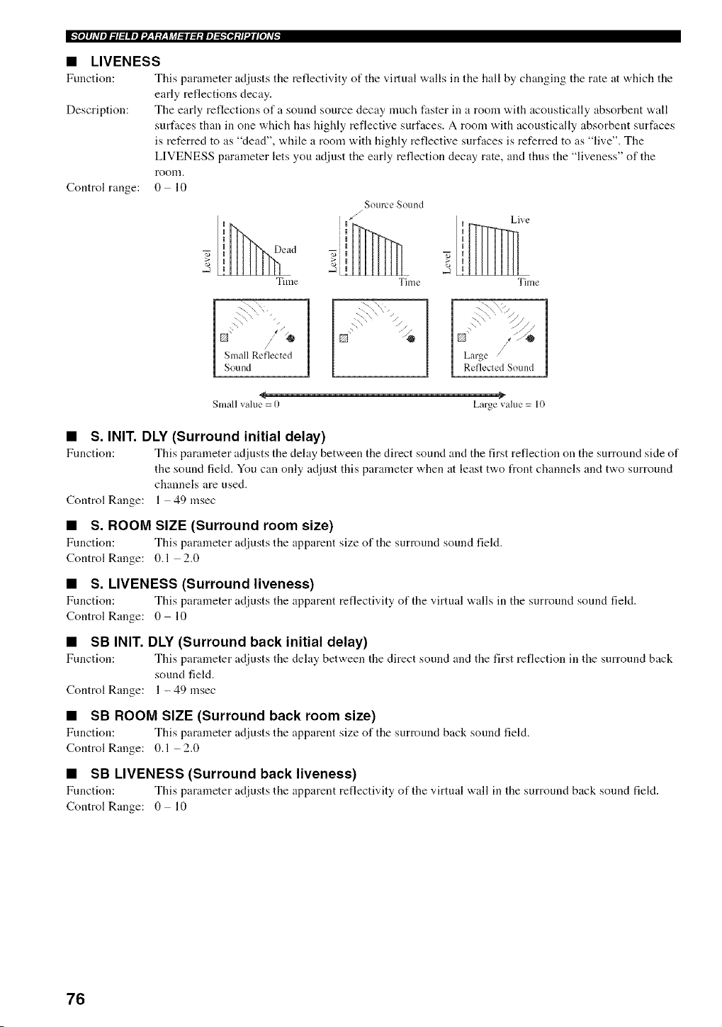
_l]lhVIl_l:lllll:l-'i:L'IJ_l_ll:l:ll]_:tl'UIl[I]_v_
• LIVENESS
Function: This parameter adjusts tile reflectivity of the virtual walls in the hall by changing tile rate at "a,hich tile
early reflections decay.
Description: The early reflections of a sound source decay much faster in a room with acoustically absorbent wall
surfaces than in one which has highly reflective surfaces. A room with acoustically absorbent surfaces
is referred to as "dead", while a room with highly reflective surfaces is referred to as "live". The
LIVENESS parameter lets you adjust the early reflection decay rate, and thus the "liveness" of the
room.
Control range: 0 lO
S otlrc L, _ound
i l/_ Live
I 7i,
2 _ 2 !
Tilne Time Time
\_'\ \+
I Small Reflected
I Sound
7\_,"
_\ -\ ,, / /
Small value = 0 Large value = 10
• S. INIT. DLY (Surround initial delay)
Function: This parameter adjusts the delay between the direct sound and the first reflection on tile surround side of
the sound field. You can only adjust this parameter when at least two front channels and two surround
channels are used.
Control Range: 1 49 msec
• S. ROOM SIZE (Surround room size)
Fuuction: This parameter adjusts the apparent size of the surround sound field.
Control Range: 0.1 2.0
• S. LIVENESS (Surround liveness)
Fuuction: This parameter adjusts the apparent reflectivity of the v*irtual walls in tile surround sound field.
Control Range: 0 10
• SB INIT. DLY (Surround back initial delay)
Fuuction: This parameter adjusts the dehty between the direct sound and the first reflection in the surround back
sound field.
Control Range: 1 - 49 msec
• SB ROOM SIZE (Surround back room size)
Function: This parameter adjusts the apparent size of tile surround back sound field.
Control Range: 0.1 - 2.0
• SB LIVENESS (Surround back liveness)
Function: This parameter adjusts the apparent reflectivity of the virtual wall ill the surround back sound field.
Control Range: 0 10
76
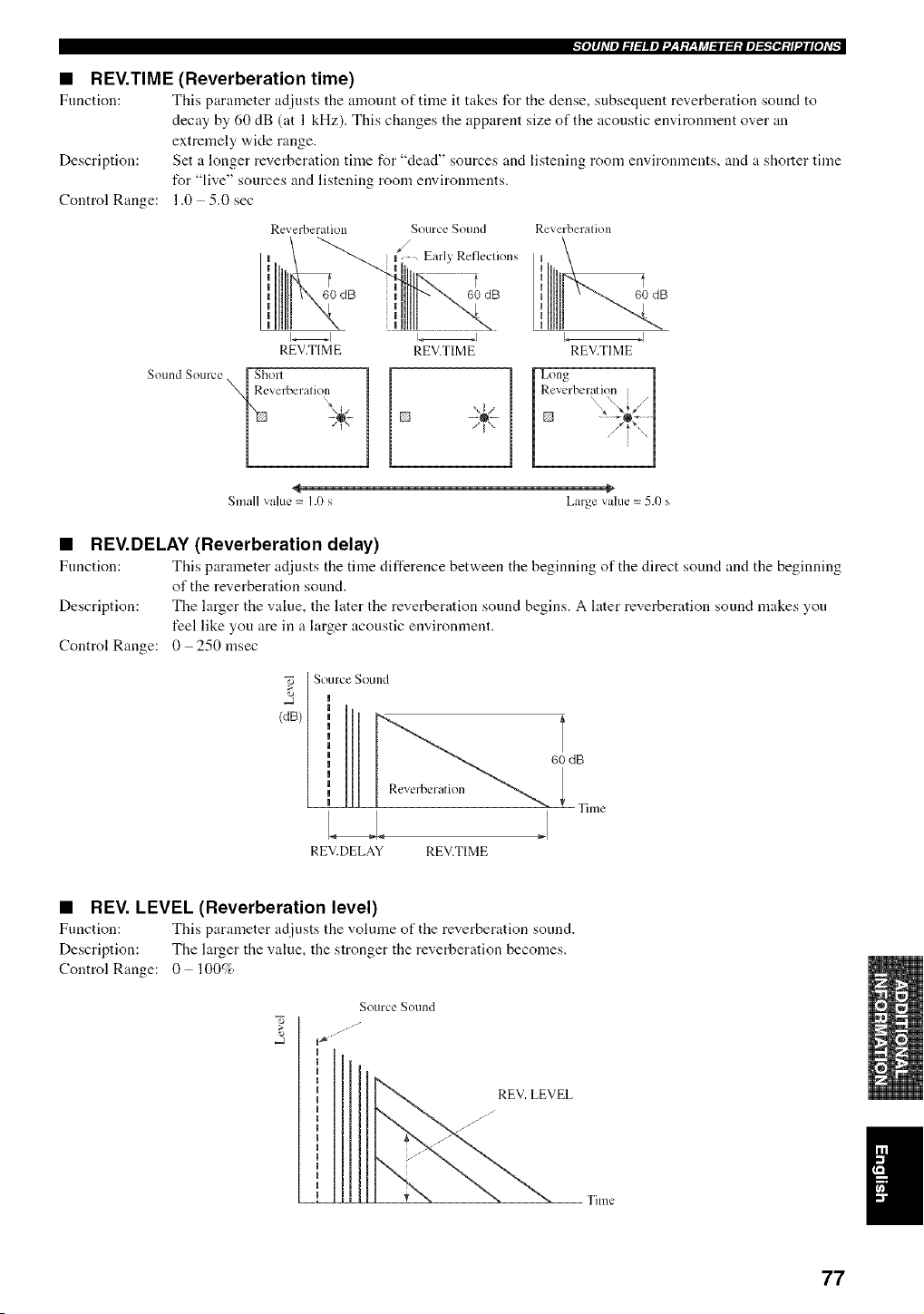
"_e]lJdlPl_l:lllel"J_,Y:L, YJ_l_ll:l:le]_'_el:tl'Jl[e]dA
• REV.TIME (Reverberation time)
Function: This parameter adjusts the amount of time it takes for the dense, subsequent reverberation sound to
decay by 60 dB (at 1 kHz). This changes the apparent size of the acoustic environment over an
extremely wide range.
Description: Set a longer reverberation time for "dead" sources and listening room environments, and a shorter time
for "live" sources and listening room environments.
Control Range: 1.0 5.0 sec
Reverberalion
t
60 dB
REV.TIME
Sound Source [ Sholl
_Reverberalioll
Source Sound Reverberalion
_/ Early Refleclions uu
t ",
Ii 60 dB B
REV.TIME REV.TIME
,,li
Small value = 1.0 s Large vakle = 5.0 s
• REV.DELAY (Reverberation delay)
Function: This parameter adjusts the time difference between the beginning of the direct sound and the beginning
of the reverberation sound.
Description: The larger the value, the later the reverberation sound begins. A later reverberation sound makes yon
feel like you are in a larger acoustic environment.
Control Range: 0- 250 msec
[ Source Sound
(dB)
60 dB
Time
REV.DELAY REV.TIME
• REV. LEVEL (Reverberation level)
Function: This parameter adjusts the volume of the reverberation sound.
Description: The larger the value, the stronger the reverberation becomes.
Control Range: 0 100%
Source Sotlnd
i_ _¸
77
I_'fo]lhqpl_l:l|el:l;l:Y;li_l:ll:l:le]_'fe]:tl'.il[o],v_
• DIALG.LIFT (Dialog lift)
Fnnction: This parameter adjusts tile height of tile front and center channel sounds by assigning some of the front
and center channel elements to the presence speakers.
Description: The larger the parameter, the higher the position of the front and center channel sound.
Choices: 0/1/2/3/4/5, initial setting is 3.
For 7ch Stereo
Fnnction: These parameter adjusts the volume level for each channel in 7-channel stereo mode.
Control Range: 0- 100%
• CT LEVEL (Center level)
• SL LEVEL (Surround left level)
• SR LEVEL (Surround right level)
• SB LEVEL (Surround back level)
• PR LEVEL (Presence level)
For PRO LOGIC IIx Music and PRO LOGIC II Music
• PANORAMA
Function: Extends the front stereo image to include the snrronnd speakers for "a,raparonnd effect.
Choices: OFF/ON, initial setting is OFF.
• DIMENSION
Fnnction: Gradnally adjusts the sound field either towards the front or towards the rear.
Control range: -3 (towards the rear) to +3 (towards the front), initial setting is STD (standard).
• CT WIDTH (Center width)
Fnnction: Adjusts the center image from all three front speakers to varying degrees. A larger value adjnsts the
center image towards the front left and right speakers.
Control range: 0 (center channel sound is output only from center speaker) to 7 (center channel sound is output only
from front left and right speakers), initial setting is 3.
For PRO LOGIC IIx Movie, Music and Game
• PLII/PLIIx (Pro Logic II/Pro Logic IIx)
Fnnction: Switches the type of Pro Logic decoding to be nsed. PLII decoding creates 5.l-channel sound from 2-
channel sources. PLIIx decoding creates 6.1/7.1-channel sound from 2-channel sources.
Choices: PLII, PLIIx
For DTS Neo:6 Music
• C. IMAGE (Center image)
Fnnction: This parameter adjusts the center image from all three front speakers to varying degrees.
Control range: 0 0.5
78
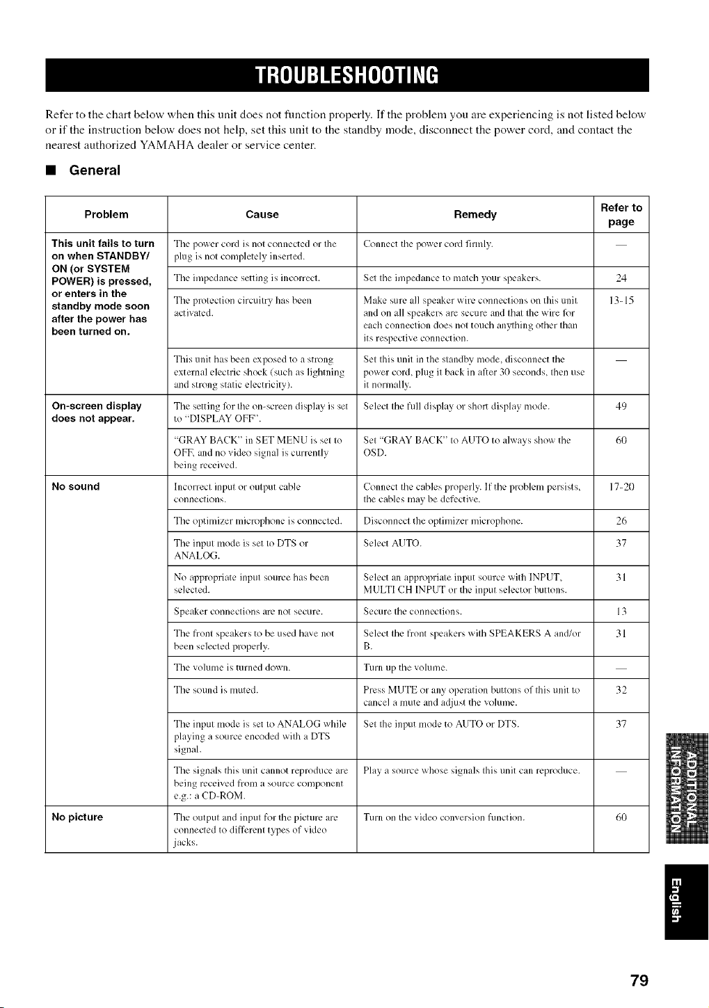
Refer to the chart below when this unit does not fimction properly. If the problem you are experiencing is not listed below
or if the instruction below does not help, set this unit to the standby mode, disconnect the power cord, and contact the
nearest authorized YAMAHA dealer or service center.
• General
Refer to
Problem Cause Remedy
page
This unit fails to turn The lX)wcr cord is nol connected or Ihe Connect the power cord firmly.
on when STANDBY/ plug is nol completely inserted.
ON (or SYSTEM
POWER) is pressed, The impedance setting is incorrect. Set Ihe impedance to malch your speakers. 24
or enters in the
The l)rolection circuilry has been Make sure all speaker wire connections on tiffs unil 13-15
standby mode soon activated, alld on all speakers are secure and Ihal Ihe wire ff)r
after the power has each col]lleclion does nol touch allylhil]g ()tiler Iha[I
been turned on. its respective connection.
Tiffs unit has been exposed to a snong Set Ihis unil in the slandby mode, disconnect the
external elecnic shock {such as lightning power cord, plug i1 back in after 3(1 seconds, Ihen use
and strong stalic electricity), it normally.
On-screen display The setting l_w Ihe on-screen display is set Select Ihe full display or short display mode. 49
does not appear, to "DISPLAY OFF".
"(;RAY BACK" in SET MENU ix sel Io Sel "GRAY BACK' Io AUTO to always show tile 60
OFF, alld no video signal is currently OSD.
being received.
No sound h]correcl input or oulput cable Connect the cables properly. If tile problem persists, 17-20
conneclions. Ihe cables may be defective.
Tile optimizer microphone is connected. Disconnect the oplimizer microphone. 26
Tile inpul mode is set Io DTS or Select AUTO. 37
ANALOG.
No al)plopriate inpul source has been Select an appropriale input source with INPUT. 31
selected. MULTI CH INPUT or the inpul selector buttons.
Speaker connections are not secure. Secure tile connections. 13
The fronl speakers to be used have not Select Ihe front speakers wilh SPEAKERS A and/or 31
been selected properly. B.
Tile volume is turned down. Turn up tile volume.
Tile sound ix muled. Press MUTE or any operalion buttons of Ihis unit Io 32
cancel a mute and adjust tile volume.
The inpul mode is set Io ANALOG while Sel Ihe input mode to AUTO or DTS. 37
playing a source encoded wilh a DTS
signal.
The signals this unit cannot reproduce are Play a source whose signals Ihis unit can reproduce.
being received frOlIl a source componell[
e.g.: a CD-ROM.
No picture The outpul and inpul for the picture are Turn on tile video conversion lkmction. 60
connected to differenl types of video
jacks.
79
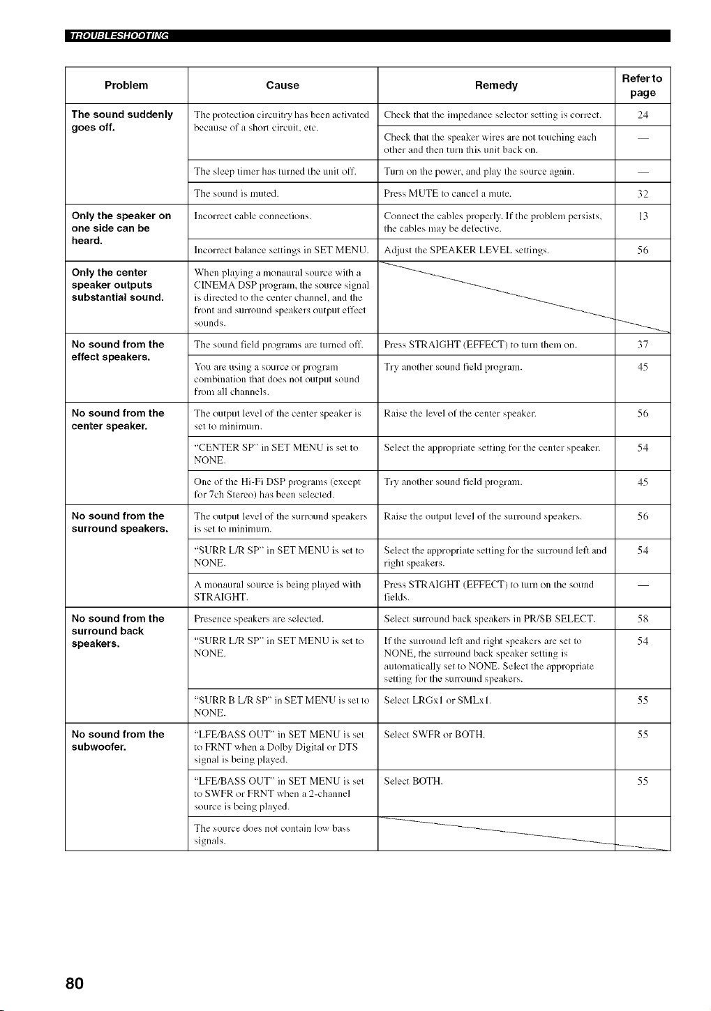
|liPiq:iq_-'iiP;qlhv[ ,
Problem
The sound suddenly
goes off.
Only the speaker on
one side can be
heard.
Only the center
speaker outputs
substantial sound.
No sound from the
effect speakers.
No sound from the
center speaker.
No sound from the
surround speakers.
No sound from the
surround back
speakers.
No sound from the
subwoofer.
Refer to
Cause Remedy
page
The protection circuitry has been activated Check that the impedance selector setting is com:ct. 24
because of a short circuit, etc.
Check that the speaker wires arc not touching each
other and then turn this unit back on.
The sleep timer has turned the unit off. Turn on the power, and play the source again.
The sound is muted. Press MUTE to cancel a mute.
Incorrect cable connections.
Incorrect balance settings in SET MENU.
When playing a monaural source with a
CINEMA DSP program, the source signal
is directed to the center channel, and the
front and surround speakers output effect
sounds.
Connect tile cables properly. If the problen/persists,
the cables may be defl:ctive.
A(liust the SPEAKER LEVEL settings.
The sound field programs are turned off. Press STRAIGHT (EFFECT) to turn then/on.
You are using a source or program Try another sound field program.
combination that does not output sound
from all channels.
The output lexel of the center speaker is Raise the level of the center speaker.
set to minimum.
"CENTER SP" in SET MEN U is set to Select the appropriate setting for the center speaker.
NONE.
One of tile Hi-Fi DSP programs (except Try another sound field program.
for 7ch Stereo) has been selected.
Tile output lexel of the surround speakers Raise the output level of the surround speakers.
is set to minimum.
"SURR L/R SP" in SET MENU is set to
NONE.
A monaural source ixbeing played with
STRAIGHT.
Select tile appropriate setting for the surround left and
right speakers.
Press STRAIGHT (EFFECT) to turn on the sound
fields.
Presence speakers are selected. Select surround back speakers in PR/SB SELECT.
"SURRL/RSP'inSETMENUissetto
NONE.
"SURRB URSP'inSETMENUissetto
NONE.
If the surround left and right speakers are set to
NONE, the surround back speaker setting is
automatically set to NONE. Select the appropriate
setting for the surround speakers.
Select LRGx I or SMLx 1.
"LFE/BASS OUT" in SET MENU is set
to FRNT when a Dolby Digital or DTS
signal is being played.
"LFE/BASS OUT" in SET MENU is set
to SWFR or FRNT when a 2-channel
source is being played.
The source does not contain low bass
signals.
Select SWFR or BOTH.
Select BOTH.
32
13
56
37
45
56
54
45
56
54
58
54
55
55
55
80
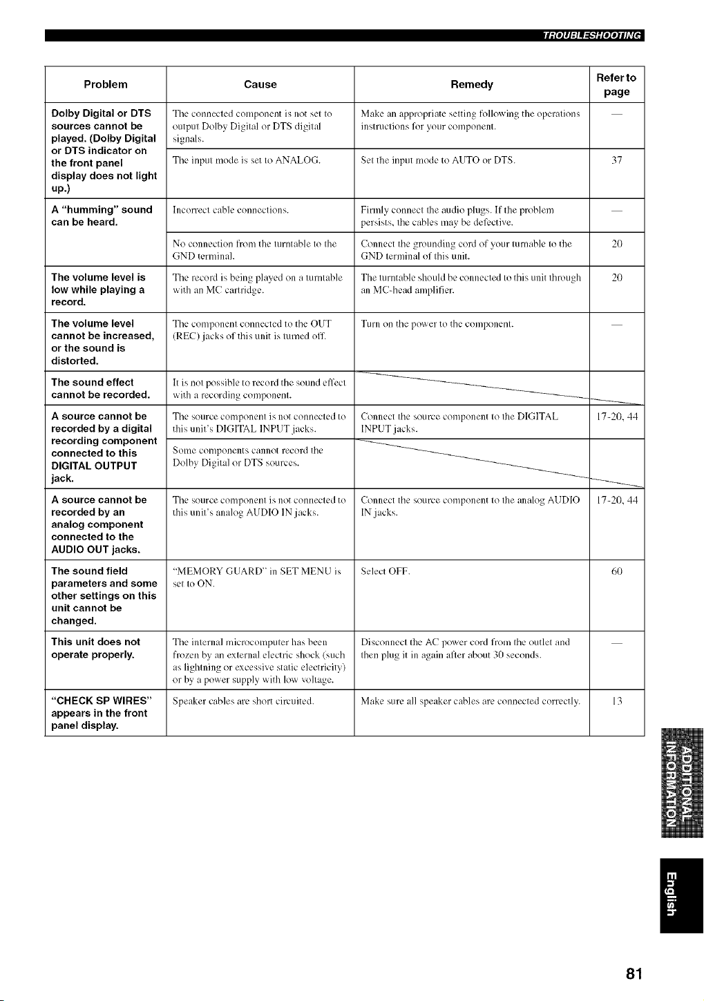
Ii _'P1:1_"_'lRqqIh'_'
Problem
Dolby Digital or DTS
sources cannot be
played. (Dolby Digital
or DTS indicator on
the front panel
display does not light
up.)
A "humming" sound
can be heard.
The volume level is
low while playing a
record.
The volume level
cannot be increased,
or the sound is
distorted.
The sound effect
cannot be recorded.
A source cannot be
recorded by a digital
recording component
connected to this
DIGITAL OUTPUT
jack.
A source cannot be
recorded by an
analog component
connected to the
AUDIO OUT jacks.
The sound field
parameters and some
other settings on this
unit cannot be
changed.
This unit does not
operate properly.
Cause
Tile connected component is not set to
output Dolby Digital or DTS digital
signals.
The input mode is set to ANALOG.
Incorrect clib]e connections.
No connection from the turntable to the
GND terminah
The record is being played on a turntable
with an MC cartridge.
Tile component connected to tile OUT
(REC) jacks of this unit ix turned off
It is not possible to record tile sound effect
with a recording component.
The source component is not connected to
this unit's DIGITAL INPUT jacks.
Some components cannot record tile
Dolby Digital or DTS sources.
Tile source component ix not connected to
this unit's analog AUDIO IN jacks.
Remedy
Make an appropriate setting following the operations
instructions for your component.
Set the input mode to AUTO or DTS.
Firmly connect Ihe audio plugs. If the problem
persists, the cables may be defective.
Connect tile grounding cord of your turnable to the
GND terminal of this unit.
The turntable should be connected to this unit through
an MC-head amplifier.
Turn on tile power to tile component.
Connect the source component to the DIGITAL
INPUT jacks.
Connect tile source component to the analog AUDIO
IN .jacks.
Referto
page
37
20
20
"MEMORY GUARD" in SET MENU is Select OFF. 60
set to ON.
The internal microcomputer has been Disconnect the AC power cord from the outlet and
frozen by an external electric shock (such then plug it in again after about 30 seconds.
as lightning or excessive static electricity)
or by a power supply with low voltage.
"CHECK SP WIRES" Speaker cables are short circuited. Make sure all speaker cables are connected correctly. 13
appears in the front
panel display.
17-20. 44
17-20,44
I
81
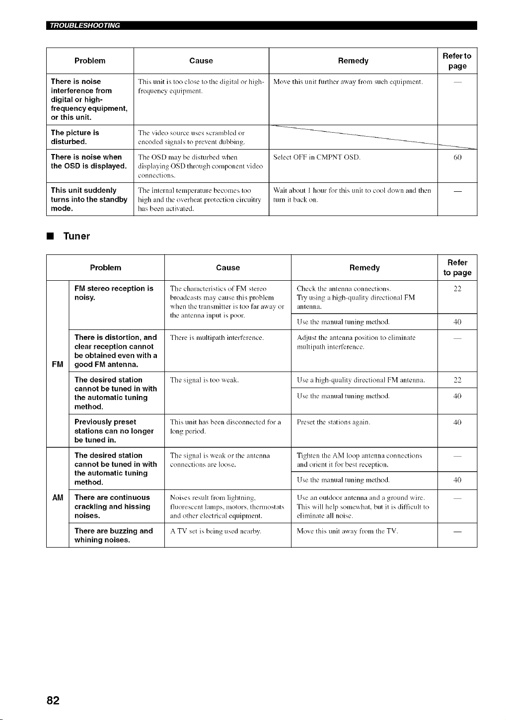
|liPiq:lq_"iiP;qlhY'
Problem
There is noise
interference from
digital or high-
frequency equipment,
or this unit.
Cause
This unit b, too close to the digital or hig]>
frequency equipment.
Remedy
Move this unit further _r_}: 11"(_/such equipment.
Referto
page
The picture is The video source uses scrambled or
disturbed, encoded signals to prevenl dubbing. _--_,,
There is noise when The OSD may be disturbed when Select OFF in CMPNT OSD. 60
the OSD is displayed, displaying OSD through component video
connections.
This unit suddenly The internal temperature becomes too W',lit about 1 hour for this unit to cool down and then
turns into the standby high and the oveflleat protection circuitry turn it back on.
mode. has been activated.
• Tuner
Refer
Problem Cause Remedy to page
FM stereo reception is 22
noisy.
FM
There is distortion, and
clear reception cannot
be obtained even with a
good FM antenna.
The desired station
cannot be tuned in with
the automatic tuning
method.
The characteristics of FM stereo
broadcasts may cause this problem
when the transmitter is too far away or
the antenna input is poor.
Check the antenna connections.
Try using a high-quality directional FM
antenna.
Use the manual tuning method. 40
There is multipath interference. A_liust the antenna position to eliminate
multipath interference.
The signal is too weak. Use a high-quality directional FM antenna. 22
Use the manual tuning method. 40
Previously preset This unit has been disconnected for a Preset the stations again. 40
stations can no longer long period.
be tuned in.
The signal is weak or the antenna
connections are loose.
The desired station
cannot be tuned in with
the automatic tuning
method.
Tighten Ibe AM loop antenna connections
and orient it for best reception.
Use the manual tuning method.
4O
AM There are continuous Noises result from lighming, Use an outdoor antenna and a ground wire.
crackling and hissing fluorescent lamps, motors, thermostats This will help somewhat, but it is difficult to
noises, and other electrical equipment, eliminate all noise.
There are buzzing and A TV set is being used nearby. Move this unit away from Ihe TV.
whining noises.
82
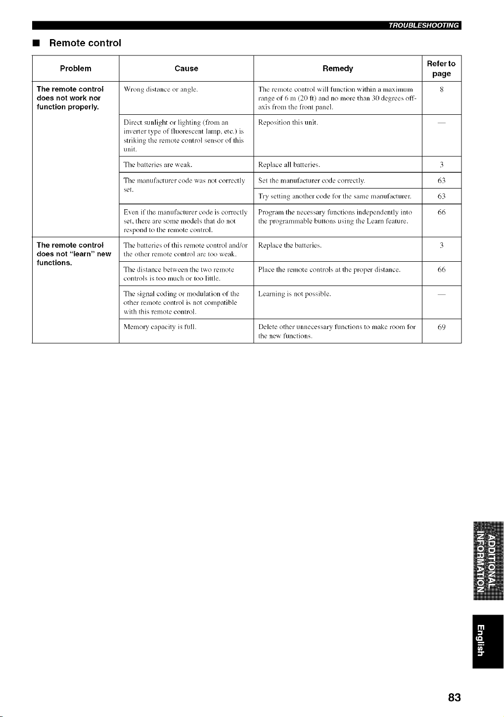
riPPlq_"lifqqlhT"
• Remote control
Refer to
Problem Cause Remedy
page
The remote control Wrong distance or angle. Tile remote control will function within a maximum 8
does not work nor range of 6 m (20 fl) and no more than 30 degrees off\
function properly, axis from tile front panel.
Direct sunlight or lighting (from an Reposition this unit.
inverter type of fluorescent lamp, etc.) is
striking the remote control sensor of this
unit.
Tile batteries are weak.
Tile manufacturer code was not correctly
set.
Replace all batteries.
Set tile manufacturer code correctly.
Try setting another code for tile same manufacturer.
Program the necessary Rmctions independently into
tile programmable buttons using Ihe Learn feature.
3
63
63
66
Even if the manufacturer code is correctly
set, there are some models that do ]lot
respond to tile ren/ote control.
The remote control The batteries of this remote control and/or Replace tile batteries. 3
does not "learn" new tile other remote control are too weak.
functions.
The distance between tile two remote Place tile remote controls at tile proper distance. 66
controls is too much or too little.
The signal coding or modulation of the Learning is ]lot possible.
other remote control is not compatible
with this remote control.
Memory capacity is full. Delete other unnecessary fimctions to make room for 69
tile new functions.
83
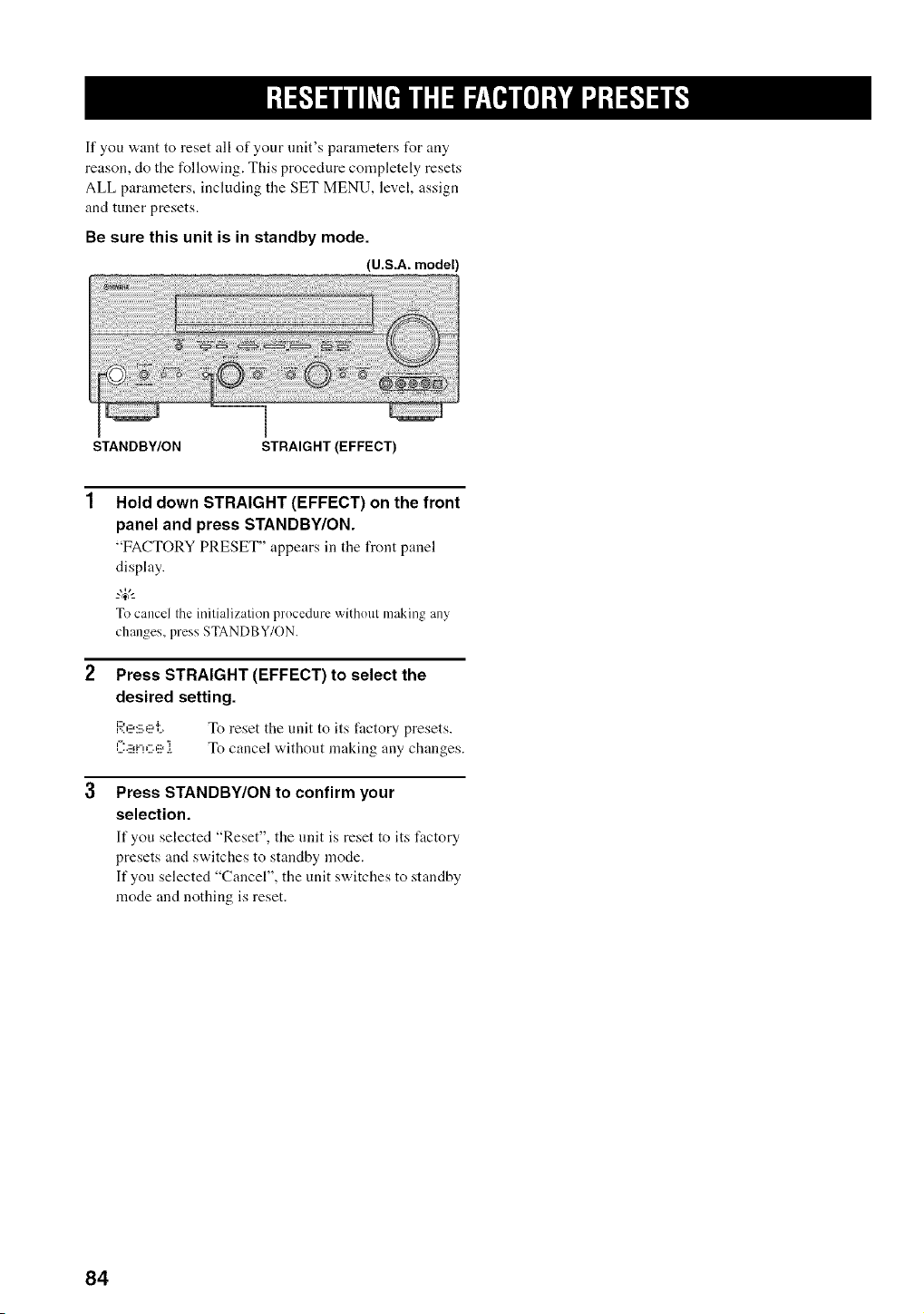
If you want to reset all of your unit's parameters for any
reason, do the following. This procedure completely resets
ALL parameters, including the SET MENU, level, assign
and tuner presets.
Be sure this unit is in standby mode.
(U.S.A. model)
STANDBY/ON STRAIGHT (EFFECT)
Hold down STRAIGHT (EFFECT) on the front
panel and press STANDBY/ON.
"FACTORY PRESET" appears in tile front panel
display.
To cancel the initialization procedure without making any
changes, press STANDBY/ON.
Press STRAIGHT (EFFECT) to select the
desired setting.
F_',l_:_'_l'i_. " r[) reset the unit to its factory presets.
]2'ii_i"!C'lii_ i To cancel without making any changes.
Press STANDBY/ON to confirm your
selection.
It"you selected "Reset", the unit is reset to its factory
presets and switches to standby mode.
If you selected "Cancel", the unit switches to standby
mode and nothing is reset.
84
• Dolby Digital
Dolby Digital is a digital surround sound system that gives
you completely independent nmlti-channel audio. With 3
front channels (left, center, and right), and 2 surround
stereo channels, Dolby Digital provides 5 full-range audio
channels. With an additional channel especially for bass
effects, called LFE (low frequency effect), the system has
a total of 5.1 -channels (LFE is counted as 0.1 channel). By
using 2-channel stereo for the surround speakers, more
accurate moving sound effects and surround sound
environment are possible than with Dolby Surround. The
wide dynamic range (from maximum to mininmm
volmne) reproduced by the 5 full-range channels and the
precise sound orientation generated using digital sound
processing provide listeners with previously unheard of
excitement and realism.
With this unit, any sound environment from monaural up
to a 5.l-channel configuration can be freely selected for
your enjoyment.
• Dolby Digital Surround EX
Dolby Digital EX creates 6 full-band'a, idth output
channels from 5.l-channel sources. This is clone using a
matrix decoder that derives 3 surround channels from the
2 in the original recording. For the best results, Dolby
Digital EX should be used with movie sound tracks
recorded with Dolby Digital Surround EX. With this
additional channel, you can experience more dynamic and
realistic moving sound especially with scenes with
"flyover" and "fly-around" effects.
• Dolby Pro Logic II
Dolby Pro Logic II is an improved technique used to
decode vast numbers of existing Dolby Surround software.
This new technology enables a discrete 5-channel
playback with 2 front left and right channels, 1 center
channel, and 2 surround left and right channels (instead of
only 1 surround channel for conventional Pro Logic
technology). Music and Game modes are also available for
2-channel sources in addition to the Movie mode.
• Dolby Pro Logic IIx
Dolby Pro Logic IIx is a new technology enabling discrete
multi-channel playback from 2-channel or multi-channel
sources. There is a Music mode for music, a Movie mode
t_r movies and a Game mode t_r games.
• Dolby Surround
Dolby Surround uses :t 4 channel analog recording system
to reproduce realistic and dynanfic sound effects: 2 front
left and right channels (stereo), a center channel for dialog
(monaural), and a surround channel for special sound
effects (monaural). The surround channel reproduces
sound within a narrow frequency range.
Dolby Surround is widely used with nearly all video tapes
and laser discs, and in ninny TV and cable broadcasts as
well. The Dolby Pro Logic decoder built into this unit
employs a digital signal processing system that
automatically stabilizes the volmne on each channel to
enhance moving sound effects and directionality.
• DTS 96/24
DTS 96/24 offers an unprecedented level of audio quality
for multi-channel sound on DVD-Video, and is filly
backward-compatible with all DTS decoders. "96" refers
to a 96 kHz sampling rate (compared to the typical 48 kHz
sampling rate). "24" refers to 24-bit word length. DTS 961
24 offers sound quality transparent to the original 96124
master, and 96124 5.1-channel sound with full-quality fidl-
motion video for nmsic programs and motion picture
sonndtracks on DVD-video.
• DTS (Digital Theater Systems)
Digital Surround
DTS digital surround was developed to replace the analog
sonndtracks of movies with a 6-channel digital sound
track, and is now rapidly gaining popularity in movie
theaters around the world. Digital Theater Systems Inc.
has developed a home theater system so that you can enjoy
the depth of sound and natural spatial representation of
DTS digital surround in your home. This system produces
practically distortion-free 6-channel sound (technically, a
left, right and center channels, 2 surround channels, plus
an LFE 0.1 channel as a subwoofer, t_r a total of 5.1 -
channels). The unit incorporates DTS-ES decoder that
enables 6.1- channel reproduction by adding the surround
back channel to existing 5. l-channel format.
• Neo:6
Neo:6 decodes the conventional 2-channel sources for 6
channel playback by the specific decoder. It enables
playback with the full-range channels with higher
separation just like digital discrete signal playback. T'a,o
modes are available; "Music mode" for playing music
sources and "Cinema mode" for movies.
85
|l'llfIJ-_'Rlill'
• CINEMA DSP
Since the Dolby Surround and DTS systems w,ere
originally designed for use in movie theaters, their effect
is best felt in a theater having many speakers and designed
for acoustic effects. Since home conditions, such as room
size, wall material, number of speakers, and so on, can
differ so widely, it's inevitable that there are differences in
the sound heard as well. Based on a wealth of actually
measured data, YAMAHA CINEMA DSP uses
YAMAHA original sound field technology to combine
Dolby Pro Logic, Dolby Digital and DTS systems to
provide the visual and audio experience of movie theater
in the listening room of your own home.
• SILENT CINEMA
YAMAHA has developed a natural, realistic sound effect
DSP algorithm for headphones.
Parameters for headphones have been set for each sound
field so that accurate representations of all the sonnd field
programs can be enjoyed on headphones.
• Virtual CINEMA DSP
YAMAHA has developed a Virtual CINEMA DSP
algorithm that allow, s yon to enjoy DSP sound field
surround effects even without any snrronnd speakers by
using virtual surround speakers.
It is even possible to enjoy Virtual CINEMA DSP using a
minimal two-speaker system that does not include a center
speaker.
iii t
• ITU-R
ITU-R is the radio conmmnication sector of the ITU
(International Telecomnmnicafion Union). ITU-R
recommends a standard speaker placement which is used
in many critical listening rooms, especially f_r mastering
pnrposes.
• LFE 0.1 channel
This channel is for the reproduction of lo'a, bass signals.
The frequency range fbr this channel is 20 Hz to 120 Hz.
This channel is counted as 0.1 because it only enforces a
low frequency range compared to the full-range
reproduced by the other 516 channels in Dolby Digital or
DTS 5.116. l-channel systems.
• PCM (Linear PCM)
Linear PCM is a signal format under which an analog
audio signal is digitized, recorded and transmitted without
using any compression. This is used as a method of
recording CDs and DVD audio. The PCM system uses a
technique for sampling the size of the analog signal per
very small unit of time. Standing for "pulse code
modnlafion", the analog signal is encoded as pulses and
then modulated for recording.
• Sampling frequency and number of
quantized bits
When digitizing an analog audio siglml, the number of
times the signal is sampled per second is called the
sampling frequency, while the degree of fineness when
converting the sound level into a numeric value is called
the number of qnantized bits.
The range of rates that can be played back is determined
based on the sampling rate, while the dynamic range
representing the sound level difference is determined by
the number of qnantized bits. In principle, the higher the
sampling frequency, the wider the range of frequencies
that can be played back, and the higher the number of
qnantized bits, the more finely the sound level can be
reproduced.
86
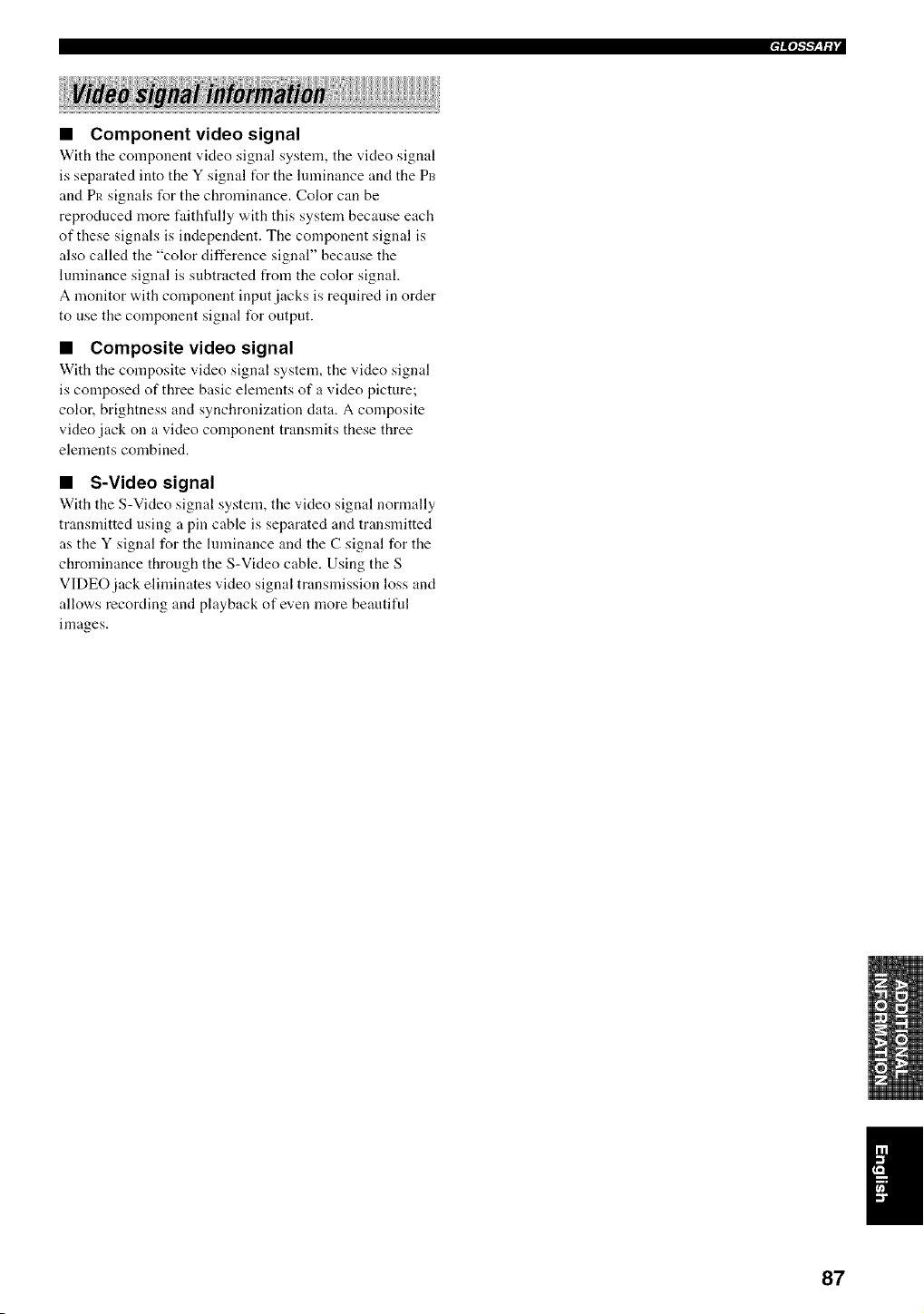
q_°l"F_til
• Component video signal
With the component video signal system, the video signal
is separated into the Y signal t_r the lmninance and the P_3
and Pit signals for the chrominance. Color can be
reproduced more faithfidly with this system because each
of these signals is independent. The component signal is
also called the "color difference signal" because the
luminance signal is subtracted from the color signal.
A monitor with component input jacks is required in order
to nse the component signal for output.
• Composite video signal
With the composite video signal system, the video signal
is composed of three basic elements of a video picture;
color, brightness and synchronization data. A composite
video jack on a video component transmits these three
elements combined.
• S-Video signal
With the S-Video signal system, the video signal normally
transmitted using a pin cable is separated and transmitted
as the Y signal for the hnninance and the C signal for the
chrominance through the S-Video cable. Using the S
VIDEO jack eliminates video signal transmission loss and
allov,,s recording and playback of even more beautiful
images.
87
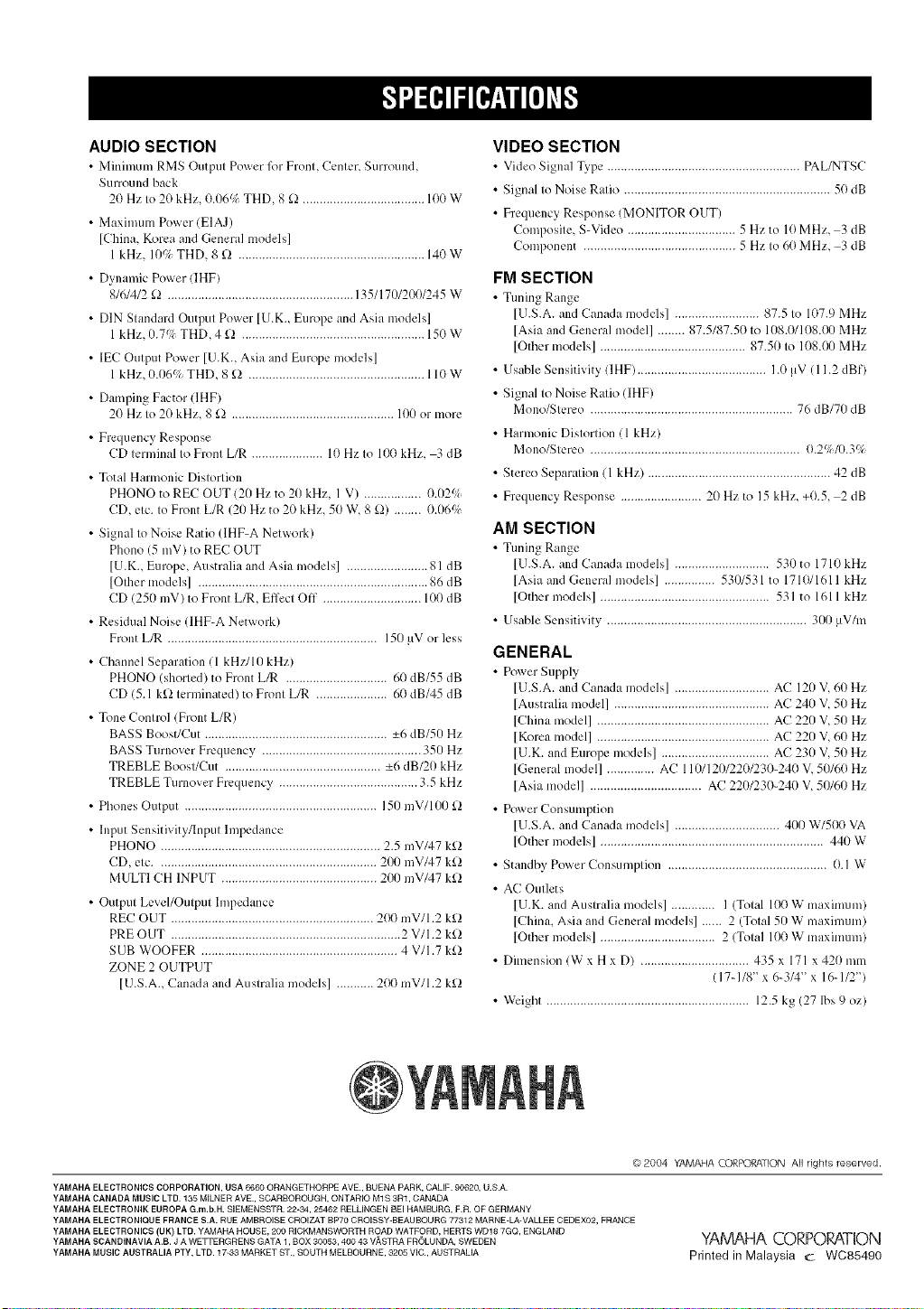
AUDIO SECTION
• Minimum RMS Output Power lbr Front, Center, Surround,
Sum_und back
20 Hz to 2(1 kHz, 0.06q THD, 8 _2 .................................... 100 W
• Maximum Power (EIAJ)
[China, Korea and General models]
1 kHz, 10P; THD, 8 £! ....................................................... 140 W
• Dynamic Power (IHF)
8/6/4/2 £2 ....................................................... 135/170/200/245 W
• DIN Standard Output Power [U.K., Europe and Asia models]
1 kHz,/).7qi THD, 4 £2 ...................................................... 150 W
• IEC Output Power [U.K., Asia and Europe models]
1 kHz, O.06q THD, 8 £) .................................................... 110 W
• Damping Factor (IHF)
20 Hz to 20 kHz, 8 £) ................................................ 100 or more
• Frequency Response
CD terminal to Front L/R ..................... 10 Hz to 100 kHz, 3 dB
• Total Harmonic Distortion
PHONO to REC OUT (20 Hz to 20 kHz, l V) ................. 0.02_
CD, etc. to Front L/R (20 Hz to 20 kHz, 50 W, 8 £!) ........ 0.06q
• Signal to Noise Ratio (IHF-A Network)
Phono (5 mV) to REC OUT
[U.K., Europe, Australia and Asia models] ........................ 81 dB
[Other models] .................................................................... 86 dB
CD (250 mV) to Front L_, Effect Off ............................. 1(I(t dB
• Residual Noise (IHF-A Network)
Front L_ .............................................................. 150 !IV or less
• Channel Separation ( 1 kH//10 kHz)
PHONO (shorted) to Front L_ .............................. 6(1 dB/55 dB
CD (5 1 k[! terminated) to Front L/R ..................... 6(1 dB/45 dB
• Tone Control (Front L/R)
BASS Boost/Cut ...................................................... -+6 dB/50 Hz
BASS Turnover Frequency ............................................... 350 Hz
TREBLE Boost/Cut .............................................. -+6 dB/20 kHz
TREBLE Turnover Frequency ......................................... 35 kHz
• Phones Output ......................................................... 150 mV/100 £!
• Input Sensitivity/Input hnpedance
PHONO ................................................................. 25 mV/47 k[!
CD, etc ................................................................. 200 mV/47 k£!
MULTI CH INPUT .............................................. 200 mV/47 k[!
• Output Level/Output hnpedance
REC OUT ............................................................ 200 mV/l 2 k[!
PRE OUT .................................................................... 2 V/I 2 k£!
SUB WOOFER .......................................................... 4 V/I 7 k£!
ZONE 2 OUTPUT
[USA, Canada and Australia models] ........... 200 mV/l 2 k£1
VIDEO SECTION
• Video Signal Type ......................................................... PAL/NTSC
• Signal to Noise Ratio ............................................................. 50 dB
• Frequency Response (MONITOR OUT)
Composite, S-Video ................................ 5 Hzto 10MHz, 3 dB
Component ............................................. 5 Hz to 60 MHz, 3 dB
FM SECTION
• Tuning Range
[USA and Canada models] ......................... 875 to 107.9 MHz
[Asia and General model] ........ 87.5/87.5(t to 108 0/108 0/) MHz
[Other models] ........................................... 87.50 to 108 0//MHz
• Usable Sensitivity (IHF) ...................................... 10 _V ( 112 dBf)
• Signal to Noise Ratio ([HF)
Mono/Sterco ............................................................ 76 dB/70 dB
• Harmonic Distortion (1 kHz)
Mono/Sterco .............................................................. 02%/039;
• Stereo Separation ( 1 kHz) ...................................................... 42 dB
• Frequency Response ........................ 20 Hz to 15 kHz, +(t5, 2 dB
AM SECTION
• Tuning Range
[U SA and Canada models] ............................ 530 to 1710 kHz
[Asia and General models] ............... 530/531 to 171(t/1611 kHz
[Other models] .................................................. 531 to 1611 kHz
• Usable Sensitivity ........................................................... 300 !_V/m
GENERAL
• Pox_er Supply
[U.S.A. and Canada models] ............................ AC 120 V, 60 Hz
[Australia model] .............................................. AC 240 V, 50 Hz
[China model] ................................................... AC 220 V, 50 Hz
[Korea model] ................................................... AC 220 V, 60 Hz
[U.K. and Europe models] ................................ AC 230 V, 50 Hz
[General model] .............. AC 110112012201230-240 V, 50/60 Hz
[Asia model] ................................. AC 2201230-240 V, 50160 Hz
• Power Consumption
[U.S.A. and Canada models] ............................... 4t)t) W/500 VA
[Other models] .................................................................. 440 W
• Standby Power Consumption ............................................... 0.1 W
• AC Outlets
[U.K. and Australia models] ............. I (Total 100 W maximum)
[China. Asia and General models] ...... 2 (Total 50 W maximum)
[Other models] .................................. 2 (Total 100 W maximum)
• Dimension (W x H x D) ................................ 435 x 171 x 420 mm
(17-118" x 6-3/4" x 16-112")
• Weight ............................................................ 12.5 kg (27 lbs 9 oz)
©2004 YAMAHA (.O£POZATION All rights reserved.
YAMAHA ELECTRONICS CORPORATION, USA 6660 ORANGETHORPE AVE., BUENA PARK, CALIF. 90620, U.S.A.
YAMAHA CANADA MUSIC LTD. 135 MILNER AVE., BGARBOROUGN, ONTARIO M1B 3R1, CANADA
YAMAHA ELECTRONIK EUROPA G.m,b.H. SIEMENSBTR. 22-34, 25462 RELLINGER BEI HAMBURG, F.R. OF GERMANY
YAMAHA ELECTRONIQUE FRANCE B.A. RUE AMBROIBE GROIZAT BP70 OROIBSY-BEAUBOURG 77312 MARNE-LA-VALLEE CEDEX02, FRANCE
YAMAHA ELECTRONICS (UK) LTD. YAMAHA HOUSE, 200 RIGHMANSWORTH ROAD WATFORD, HERTS WD18 7GQ, ENGLAND
YAMAHA SCANDINAVIA A.B. J A WETTERGREHS GATA 1, BOX 30053, 400 43 V,'%BTRA FBOLUNDA, SWEDEN
YAMAHA MUSIC AUSTRALIA PTY, LTD. 17-33 MARKET ST., SOUTH MELSOUBN E, 3205 VIG., AUSTRALIA
YAMAHA CORPORATION
Printed in Malaysia c WC85490