Loading ...
Loading ...
Loading ...
6
• If the windows are large, use additional window bracket
(B4) to cover your window aperture, extending it to the
required length, then blocking it with the locking wing nut
supplied (g. 3).
3
• Insert and lock the accessory for window bracket (B1) al-
ready assembled to the air exhaust hose, into the slot of the
window bracket (g. 4).
4
Click
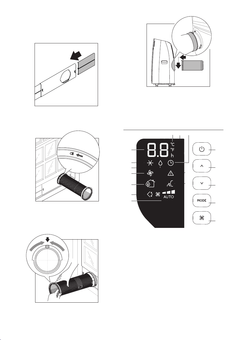
• In order to facilitate the tting of the air exhaust hose (B2)
in the relevant housing located on the rear side of the ap-
pliance, position the hose adapter‘s tabs (B3) in a vertical
axis as shown in g. 5 .
5
• Fit the air exhaust hose (B2) in the relevant housing located
on the rear side of the appliance (g . 6).
6
SLIDING WINDOWS
•
Thanks to the locking wing nut, it’s possible to use the win-
dow bracket also for sliding windows. Position the hole of the
bracket so to allow a correct installation of the exhaust hose
.
OPERATING FROM THE CONTROL PANEL
C1
C15
C13
C12
C11
C10
C9
C8
C7
C6
C16C17
C3
C4
C2
C5
C14
DESCRIPTION OF THE CONTROL PANEL (C)
C1. ON/STAND-BY (on/o) key
C2. Function selection key MODE (air conditioning, dehumidi-
fying, fan)
C3. Increase key
C4. Decrease key
C5. Fan speed selection key (MIN/MED/MAX/AUTO)
C6. Air conditioning symbol
C7. Dehumidifying symbol
C8. Fan symbol
C9. ECO REAL FEEL symbol/status indicator
C10. Swing symbol
C11. Fan speed indicator
C12. ARCTIC WHISPER EXTREME symbol
Loading ...
Loading ...
Loading ...