PSX006XL
PSD008XL
PSD010XL
392
836
1266
MODEL
AMPS CFM
1.26
2.99
4.84
PERFORMANCE · QUALITY · CUSTOMER SERVICE
REVISED: JANUARY 1, 2024
© 2 0 2 3 T R A D E - W I N D M A N U F A C T U R I N G , L L C
P R O V E R B S 2 2 : 2 9
I N S T A L L A T I O N I N S T R U C T I O N S
& P R O D U C T S P E C I F I C A T I O N S
T R A D E - W I N D ®
I N - L I N E B L O W E R / V E N T I L A T O R
1
WEIGHT
12 lbs.
19 lbs.
21 lbs.
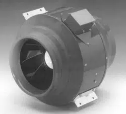
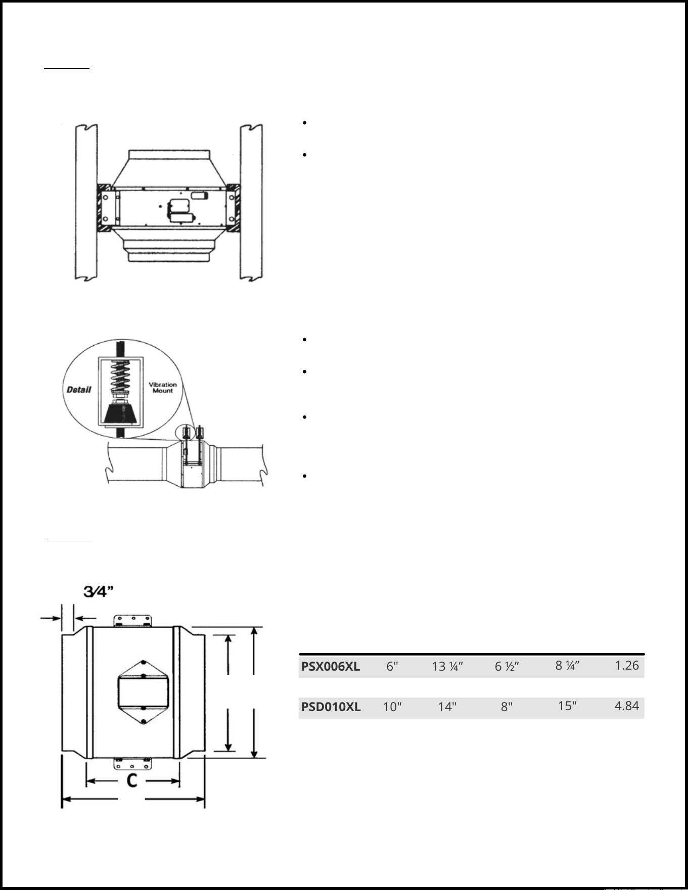
Featuring a galvanized steel housing Trade-Wind® In-Line Blowers are designed to be installed “in-line” with a Trade-Wind® or
comparable wood hood liner. These fans are specifically designed to provide efficient, high velocity air movement by combining
the best elements of high flow axial designs with the power of a centrifugal squirrel cage blower. Direct Drive motor construction
eliminates the need for continuous belt alignment, tension adjustments and maintenance.
DESCRIPTION
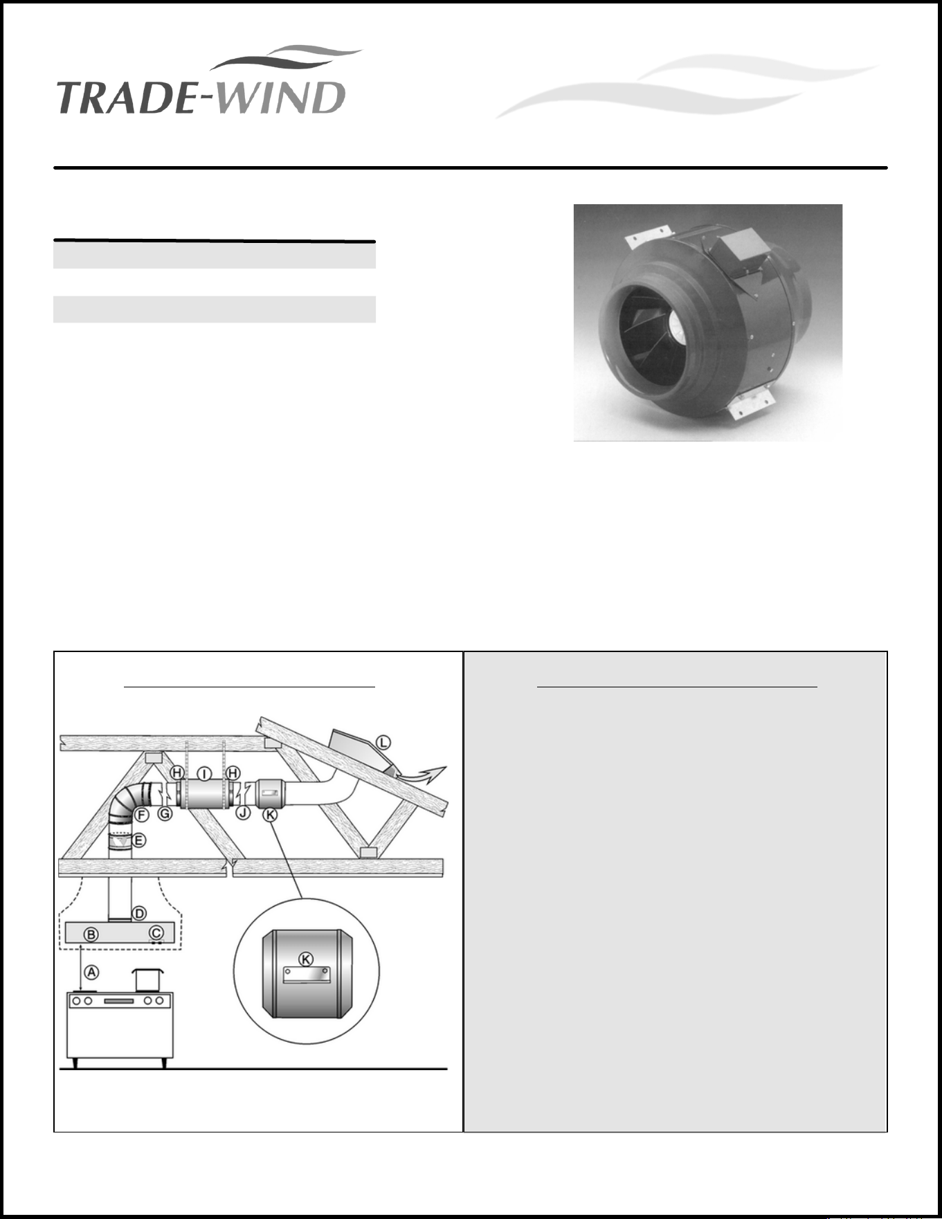
(This applies to Illustration on the Left)
Trade-Wind® In-Line Blower Mechanism (K), Duct Silencer (I),
Damper (E) and two Fast Clamps (H) which are placed on each
side of the Duct Silencer (I). This picture illustrates the required
progression but the orientation can /will vary. The In-Line
Blower and Duct Silencer in this illustration are in a horizontal
position, they can be installed at any angle. Attic installations
are highly recommended.
To ensure the overall ventilation system operates as designed,
please carefully review the Installation Instructions included
with the individual products. These guidelines are the
manufacturer’s suggestions. Always observe local, municipal
and state building codes.
Note: In the illustration (left): F is the ducting elbow; G is the duct
pipe of some variable length for specific application; J is the same
as G but on the other side of the Duct Silencer(I); and L is the Roof
Cap or Wall Cap that is to be sized the same square inches
opening as duct pipe. The A, B, C, and D are the specifications
dictated by the the customer's Designer or Builder.
INSTALLATION ILLUSTRATION INSTALLATION CONSIDERATIONS
See page 4.
DIMENSIONS
TYPICAL INSTALLATION
© 2 0 2 3 T R A D E - W I N D M A N U F A C T U R I N G , L L C
P R O V E R B S 2 2 : 2 9
Installer:
Owner:
Please leave Installation Instructions with the product installation instructions.
Please keep Installation Instructions for local electrical inspector’s use and for future reference.
WARNINGS:
IMPORTANT:
TIPS:
Must be followed carefully to avoid personal injury.
Must be followed carefully to avoid damage and incorrect installation.
Contains helpful information to facilitate installation.
WARNING! TO REDUCE THE RISK OF FIRE, ELECTRICAL SHOCK, OR INJURY TO PERSONS OBSERVE THE FOLLOWING:
a) Use this unit only in the manner intended by the manufacturer. If you have any questions, please contact the
manufacturer at the address or telephone number listed in the warranty.
b) Before servicing or cleaning unit, switch power off at service panel, lock service panel, and lock the service disconnection
means to prevent power from being switched on accidentally. When the service disconnecting means cannot be locked,
securely fasten a prominent warning device, such as a tag, to the service panel.
c) Installation work and electrical wiring must be done by qualified person(s) in accordance with all applicable codes and
standards, including fire-rated construction.
CAUTION: For general ventilating use only. Do not use to exhaust hazardous or explosive materials and vapors.
Before beginning installation, please thoroughly read and become familiar with these instructions. Installation
and service must be completed by a qualified installer. Failure to properly install this product may void the
warranty.
READ AND SAVE THESE INSTRUCTIONS
CAUTION: This unit has an unguarded impeller. Do not use in locations readily accessible to people or animals. WEAR
HAND PROTECTION AND STAY CLEAR OF SHARP EDGES. The compactness and adaptability of the model PSD
blower permits easy installation. The units are shipped fully assembled and can be mounted at any angle.
Because this unit has rotating parts, safety precautions should be exercised during all phases of installation,
operation and maintenance. Remove unit from package and inspect before installation. If damaged, report
damage to carrier. DO NOT operate this unit with visible damage to the blower or impeller assembly. Screen
guards must be installed when blower will be within reach of personnel, within (7) feet of the working area, or
when advisable for safety.
2
WARNING! DO NOT CONNECT POWER SUPPLY until blower is completely installed. Make sure electrical
service to the blower is locked in “OFF” position.
a) Check voltage at blower to see if it corresponds to the motor name plate.Installation work and electrical wiring must be
done by qualified person(s) in accordance with all applicable codes and standards, including fire-rated construction.
b) Sufficient air is needed for proper combustion and exhausting of gasses through the flue (chimney) of fuel burning
equipment, (e.g., gas water heater, gas furnace) to prevent back drafting.
c) Follow the heating equipment manufacturer’s guideline and safety standards such as those published by the National
Fire Protection Association (NFPA) and the American Society for Heating, Refrigeration and Air Conditioning Engineers
(ASHRAE) and the local code authorities.
d) When cutting or drilling into wall or ceiling, do not damage electrical wiring and other hidden utilities. Ducted blowers
must always be vented to the outdoors.
e) If this unit is to be installed over a tub or shower, it must be marked as appropriate for the application and be
connected to a GFCI (Ground Fault Circuit Interrupter) –protected branch circuit.
f) NEVER place a switch where it can be reached from a tub or shower.
g) All units are suitable for use with solid-state speed control.

© 2 0 2 3 T R A D E - W I N D M A N U F A C T U R I N G , L L C
P R O V E R B S 2 2 : 2 9
WARNING! TO REDUCE THE RISK OF FIRE, ELECTRICAL SHOCK, OR INJURY TO PERSONS OBSERVE THE FOLLOWING:
a) Installation work and electrical wiring must be done by qualified person(s) in accordance with all applicable codes
and standards, including fire-rated construction codes and standards.
b) Sufficient air is needed for proper combustion and exhausting of gasses through the flue (chimney) of fuel burning
equipment to prevent back drafting. Follow the heating equipment manufacturer's guidelines and safety standards
such as those published by the National Fire Protection Association (NFPA) and the American Society for Heating,
Refrigeration and Air Conditioning Engineers (ASHRAE) and the local code authorities.
c) When cutting or drilling into wall or ceiling, do not damage electrical wiring and other hidden utilities.
d) Ducted fans must always be vented to the outdoor.
PART 1: PLANNING THE INSTALLATION
For best and quietest performance, the In-Line Blower should be installed in the attic, near or slightly beyond the mid-
point of the duct system. In installations requiring the blower be in a chase or wood-type hood over the range (e.g., no attic
above the kitchen), the duct silencer will not be as effective in absorbing motor noise. In addition, there will likely be motor
sound transmitted through the walls of the chase, bypassing the duct silencer. Given the high performance of Trade-Wind®
In-Line Blowers, it is highly recommended that the blower NOT be attached directly to the liner or in a chase
immediately above the liner unless a Trade-Wind® brand duct silencer is installed between the blower and liner and
neoprene lined FC Clamps* are used.
Trade-Wind® brand Professional Series ventilation systems can be installed in an infinite variety of configurations. The In-Line
Blower and Duct Silencer can be installed at any angle.
After properly aligning and supporting the blower, connect it to the duct. Fasten in place by using sheet metal screws
and tape or preferably FC Clamps*. Fast Clamps (FC Clamps) are the recommended connectors for connecting the blower
to the duct system. FC Clamps are easy to connect and work extremely well as a vibration absorber and noise
suppressor. They are made of steel and are lined with a 0.3” neoprene pad. If FC Clamps are used to connect the blower
to the duct, it is not as necessary to use them on the Duct Silencer for vibration suppression. FC Clamps are available
from Trade-Wind® through your Trade-Wind® supplier.
CONNECTING THE BLOWER/VENTILATOR:
3
CAUTION: DO NOT hang PSD model blowers/ventilators from the FC Clamp’s hanging tabs. Instead, use the
integral brackets bolted to the blower housing.
Hanger-type vibration isolators and suspension hardware (e.g., threaded rod, slotted angle iron, hurricane
strap) are not supplied with blower. If the blower is suspended with these items, they will absorb much of the
motor’s minor vibration.
For more information about vibration absorbers, visit the following internet sites:
www.grainger.com (e.g., for WW Grainger Item 4C879)
www.vibration-absorbers.com
*FC Clamps are available from Trade-Wind® (Trade-Wind Manufacturing, LLC) through your Trade-Wind®
supplier. Ask for model numbers FC6 (6”), FC8 (8”) or FC10 (10”), 2 per box.
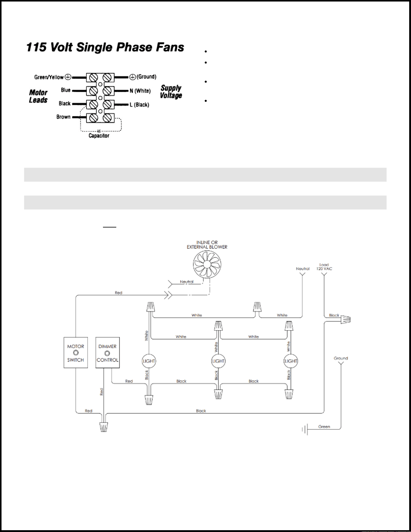
PSX006XL
PSD008XL
PSD010XL
1.26
2.99
4.84
8 ¼”
15 ½"
15"
6 ½”
7"
8"
13 ¼”
12 ½"
14"
6"
8"
10"
A
B
D
MODEL AMPS
D
CB
A
© 2 0 2 3 T R A D E - W I N D M A N U F A C T U R I N G , L L C
P R O V E R B S 2 2 : 2 9
PART 2: SECURING THE BLOWER/VENTILATOR
Follow all applicable codes when installing this unit.
Build and install wood supports to framing structure for blower
mounting.
Attach blower directly to wood supports.
The In-Line Blower’s mounting brackets are designed for flexible and easy
installation at any angle—horizontal, vertical or diagonal.The brackets
should be bolted directly to a 2” x 4” type wood framing structure (e.g., an
attic truss) or suspended by threaded rod, slotted angle-iron or hurricane
strap. The installation should be sufficient to support the blower’s weight.
Follow all applicable codes when installing this unit.
Equipment should be hung in position with temporary fixtures that can
be removed after vibration hangers* are installed.
Optional vibration hanger* may be fastened directly to the structure or
somewhere between the suspended unit. Be sure not to over tighten
the neoprene element. Install hangers.
If threaded rod is used, turn nuts on rod assembly clockwise one
complete turn on each hanger.Repeat this procedure until temporary
hanging fixtures are loose and blower is suspended completely on the
vibration hangers.
Remove temporary fixtures and level ducting and blower by taking
additional turns on the spring / top hanger rod nut as required.
MOUNTING ILLUSTRATION OPTION 1
MOUNTING ILLUSTRATION OPTION 2
4
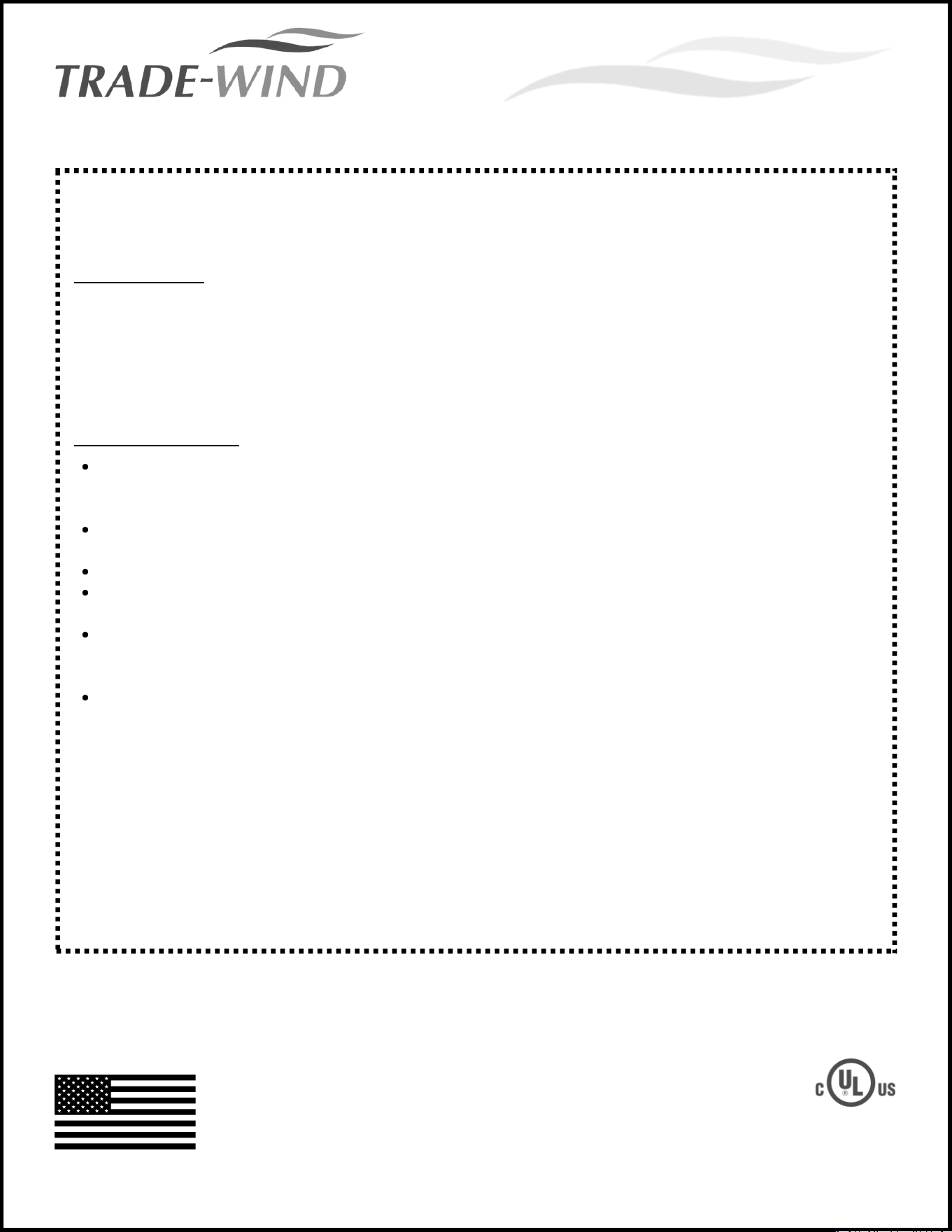
PART 3: ELECTRICAL CONNECTION
DIMENSIONS
DIMENSIONS DATA & AMPERAGE
*Above specifications apply to picture on left
BLACK
WHITE
GREEN
RED
120 VOLT AC FROM ELECTRICAL PANEL (USUALLY BLACK) TO LINER
NEUTRAL FROM ELECTRICAL PANEL (USUALLY WHITE) TO LINER
GROUND FROM ELECTRICAL PANEL (USUALLY GREEN) TO LINER
120 VOLT AC VARIABLE CONTROL FROM LINER TO 120 VOLT AC VARIABLE SPEED VENTILATOR
CAUTION: DO NOT CONNECT THIS WIRE TO A 3-SPEED BLOWER.
© 2 0 2 3 T R A D E - W I N D M A N U F A C T U R I N G , L L C
P R O V E R B S 2 2 : 2 9
WARNING:
Ensure the power supply is disconnected before proceeding.
Verify that the power supply matches the ratings found on
the blower data label before proceeding.
The complete blower unit must be properly grounded at all
times when electrical power is applied.
Do not ground the appliance with the neutral (white) house
supply wire. A separate ground wire must be utilized.
Failure to complete electrical connections properly may
result in damaged or non-functional systems. Follow
instructions carefully to ensure proper installation.
VARIABLE-SPEED CONTROL WIRING DETAILS (FOR REMOTE/IN-LINE BLOWERS)
It is the owner’s responsibility to ensure that a qualified person performs the electrical connection of this appliance. The electrical
installation, including minimum supply wire size, must comply with the National Electric Code ANSI/NFPA 70-1990 (or latest
revision) and local codes and ordinances. A copy of this standard may be obtained from:
National Fire Protection Assoc.
1 Batterymarch Park
Quincy, MA 02269
5
PERFORMANCE · QUALITY · CUSTOMER SERVICE
W A R R A N T Y
© 2 0 2 3 T R A D E - W I N D M A N U F A C T U R I N G , L L C
P R O V E R B S 2 2 : 2 9
8 0 0 W E S T G R A N T S T R E E T
P H O E N I X , A Z 8 5 0 0 7
1 - 8 0 0 - 9 5 5 - 5 7 3 7
6 0 2 - 9 0 0 - 8 5 0 0
T - W U S A . C O M
MA D E I N P HO E NI X, AZ US A
WARRANTY REVISED: JANUARY 1, 2023
TRADE-WIND Manufacturing, LLC® has a policy of continuous improvements and
reserves the right to modify (at any time without notice) any or all of its products,
features, designs, components and specifications. For further information on
installation and wiring, see the installation instructions included with the product or
visit us on the web.
T R A D E - W I N D ® V E N T I L A T I O N P R O D U C T S
For more information, please contact your dealer or your TRADE-WIND® representative.
What IS Covered:
TRADE-WIND Manufacturing, LLC® warrants its TRADE-WIND® Ventilation Products to the original user to
be free of defects in materials and workmanship for three (3) years from the date of purchase.
TRADE-WIND Manufacturing, LLC®, at its option, will repair or replace the complete unit or any defective
component without charge. This warranty may be voided if any unauthorized service, alterations, or
repairs are made to the product.
What is NOT Covered:
Normal maintenance and service of any product that has been subject to misuse, negligence, accident,
or installation inconsistent with the recommended TRADE-WIND® Installation Instructions and TRADE-
WIND® Best Practices Guidelines.
Product used other than for normal in-home use or products used outside of the United States and
Canada.
Damage to the product caused by accident, fire, flood, or other acts of God.
Service calls to educate the customer in the proper use and care of the product, change fuses, or to
reset the circuit breakers.
Service calls to correct faulty installation, such as performance issues relating to improperly sized
ducting or restrictive roof caps, are not covered and will, by default, be charged back to the
Homeowner.
Light bulbs are not covered under warranty.
TRADE-WIND Manufacturing, LLC® disclaims and excludes any liability for implied warranties or for
incidental or consequential damages wherever permitted by law. There are no implied warranties of
merchantability or fitness for a particular use or purpose. This warranty gives you specific legal rights, and
you may also have other rights, which vary from state to state.
For Service: If you need service on your TRADE-WIND® Ventilation Product, visit our website at: www.t-
wusa.com and click on the warranty tab. Fill out the simple form providing the model number, serial
number, date of purchase, and brief description of the problem. Proof of purchase will also be required.