Loading ...
ISTRUZIONI DI MONTAGGIO E MANUTENZIONE PER MONOCOMANDO GIREVOLE E MISCELATORE CON DOCCETTA
ESTRAIBILE. SI RACCOMANDA DI LEGGERE ATTENTAMENTE LE ISTRUZIONI, PRIMA DI PROCEDERE ALL’INSTALLAZIONE.
QUESTA ISTRUZIONE DEVE ESSERE ASSOLUTAMENTE CONSEGNATA AL CLIENTE.
Prima dell’installazione e messa in funzione.
Attenzione! I tubi d’alimentazione devono essere sciacquati con cura prima dell’installazione del miscelatore, in modo che non rimangano
trucioli, residui di saldatura o canapa, o altre impurità all’interno dei tubi. Attraverso tubazioni non sciacquate a fondo o attraverso la rete
idrica generale, nel miscelatore possono entrare corpi estranei in grado di danneggiare le guarnizioni/guarnizioni ad anello. Generalmente
si consiglia di installare un filtro sul raccordo principale dell’acqua. Prima della messa in funzione, svitare l’aeratore e sciacquare molto
bene.
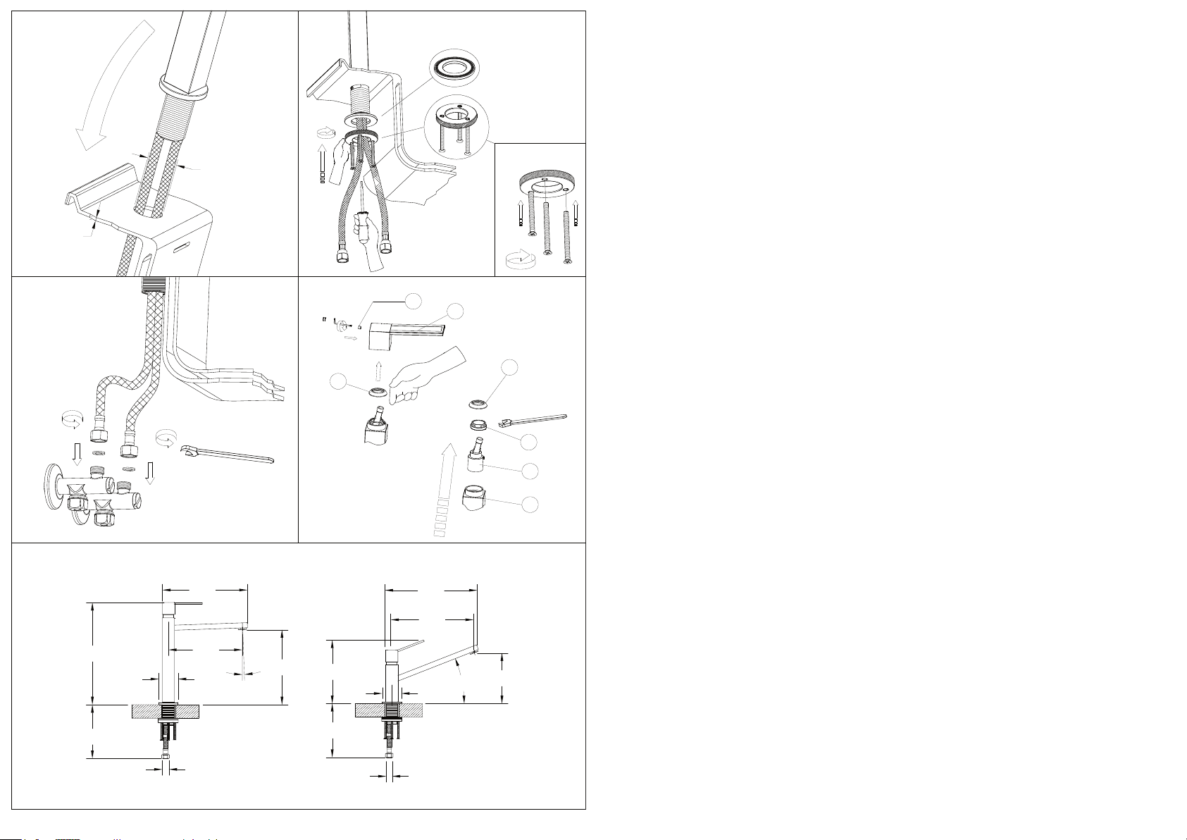
- Montaggio (Fig. 1 - Fig. 2 - Fig. 3)
Prima di inserire il monocomando nel foro del lavello assicurarsi che la guarnizione di base sia ben posizionata nella propria sede e che
i flessibili di alimentazione siano ben avvitati al corpo del rubinetto. Sistemare il monocomando sul foro del lavello orientando la bocca di
erogazione verso la vasca del lavello. Assemblare le viti in dotazione con la ghiera forata (vedi fig. 2b). Inserire la flangia piatta con OR
contro il piano inferiore e bloccarla avvitando manualmente la ghiera. Stringere con forza le viti installate in precedenza per assicurare il
fissaggio. Procedere al collegamento dei flessibili alla rete di alimentazione.
- Sostituzione cartuccia (Fig. 4)
Prima di sostituire la cartuccia, accertarsi che il raccordo dell’acqua sia chiuso. Svitare la vite di fissaggio (A) utilizzando una chiave a
brugola, estrarre quindi la maniglia (B) sfilandola dalla cartuccia (E). Sollevare la ghiera copricartuccia (C). Svitare la ghiera di fissaggio
(D) e togliere la cartuccia (E) dal corpo del miscelatore (F). Infine introdurre la nuova cartuccia, accertandosi che le due spine di centraggio
siano nella loro sede e che le guarnizioni siano correttamente posizionate.
- Pulizia del miscelatore
Superficie: le superfici cromate sono sensibili a detergenti anti-calcare, acidi o abrasivi. Le superfici colorate sono verniciate con una
speciale laccatura a fuoco e non devono in nessun caso essere pulite con detergenti acidi, abrasivi o contenenti alcol. Pulire solo con
acqua ed un panno morbido/pelle!
Miscelatore: pulire regolarmente l’aeratore (rompigetto), in modo che il getto dell’acqua rimanga forte e non si formi alcun residuo nel
miscelatore che possa causare un gocciolamento. Per effettuare quest’operazione, svitare l’aeratore (rompigetto) e lasciarlo qualche
ora in acqua e aceto. Eliminare i residui di calcare e avvitare nuovamente l’aeratore (non dimenticare la guarnizione). Qualora non si
osservassero queste istruzioni decadrebbero i diritti di garanzia.
- Dati tecnici
· Pressione minima d’esercizio 0,5 bar
· Pressione massima d’esercizio 5 bar
· Pressione d’esercizio consigliata 3 bar (in caso di pressione dell’acqua superiore ai 5 bar si consiglia l’installazione di riduttori di
pressione)
· Temperatura massima d’esercizio 70°C
ASSEMBLING AND MAINTENANCE INSTRUCTIONS FOR SINGLE-LEVER MIXER AND SINGLE-LEVER MIXER WITH FLEXIBLE
SHOWER. WE KINDLY ASK YOU TO READ THIS INSTRUCTION CAREFULLY, BEFORE CARRYING OUT THE INSTALLATION AND
THE SETTING TO WORK. THIS INSTRUCTION SHOULD BE ABSOLUTELY HANDED TO THE USER.
- Before installation and setting to work
Attention! The feeding pipes have to be rinsed thoroughly before the installation of the mixer, so that no shavings, welding or hemp
residual or other dirt can be found in the pipes. Foreign bodies can enter the mixer through the rinsed pipes or the general
water plant and could damage the washers/ring washers. Normally, it is recommended to install a filter on the main water union.
Before the setting to work, unscrew the aerator and rinse it very well.
- Assembling instructions for the single-lever mixer (Fig. 1 - Fig. 2 - Fig. 3)
Before inserting the single-lever in the hole of the sink make sure that the base gasket is properly positioned in its slot and that supply
hoses are watertight. Place the single-lever on the hole of the sink rotating the supply mouth towards the basin of the sink. Assemble the
screws with the pierced ring nut (see fig. 2b). Insert the flat flange with OR against the lower plane and lock it screwing the ring nut. Steadily
fasten the screws previously installed to fasten at best. Connect the hoses to the supply network links.
- Replacement of the cartridge (Fig. 4)
Before carrying out this operation make sure that water supplòy is turned off. Unscrew the fastening screw (A) using an Allen wrench, take
out the handle (B), removing it from the cartridge (E). Lift the finishing ring nut (C). Unscrew the fixing ring nut (D) and take the cartridge
(E) out form the mixer body (F). Then put the new cartridge, verifying that the two centering pins enter into the respective seats and that
gaskets are well positioned
- Cleaning of the mixer
Surfaces: the chromed surfaces are sensitive to anti-limescale, acid or abrasive detergents. The coloured surfaces are painted with a
particular lacquering and may never be cleaned with acid, abrasive or alcohol containing detergents. Clean with water and a soft cloth/hide
only! Mixer: regularly clean the aerator (jetbreaker) so that the water jet remains strong and no residual can be formed, which could cause
dripping. In order to carry out this operation, unscrew the aerator (jetbreaker) and put it in water and vinegar during some hours. Eliminate
the residual from limescale and screw the aerator again (don’t forget the washer). The guarantee rights will be lost, if these instructions
aren’t observed.
- Technical data
· Minimum working pressure 0,5 bar
· Maximum working pressure 5 bar
· Recommended working pressure 3 bar (in case of water pressure higher than 5 bar it is recommended to install pressure reducers)
· Maximum working temperature 70°C
INSTRUCTIONS POUR LE MONTAGE ET L’ENTRETIEN DU MÉLANGEUR MONO-COMMANDE ET DU MÉLANGEUR MONO-
COMMANDE À PETITE DOUCHE FLEXIBLE. NOUS VOUS PRIONS DE LIRE ATTENTIVEMENT CES INSTRUCTIONS AVANT DE
FAIRE L’INSTALLATION ET LA MISE EN FONCTION. CES INSTRUCTIONS DEVRONT ÊTRE REMISES OBLIGATOIREMENT À
L’UTILISATEUR.
- Avant l’installation et la mise en fonction.
Attention! Les tubes d’alimentation doivent être rincés avec soin avant l’installation du mélangeur, de façon qu’il ne reste pas de riblons,
de restes de soudure ou de chanvre, ou d’autres saletés à l’intérieur des tubes. A travers les tuyauteries qui ne sont pas
Fig. 3
Ch. 19mm
Fig. 4
A
C
B
C
D
E
F
Fig. 5
Fig. 2b
MFQ7
705
303
G 3/8"
2°
223
Ø55
213
245
267
237
150
189
705
22°
G 3/8"
Ø55
Fig. 1 Fig. 2
Ch. 21mm
Ch. 2,5mm
MFQ8
40 max
Ø33.5
dimensioni in mm - measures in mm - dimensions en mm - Maß im mm - medidas en mm