

G
a
Inst
a
a
s
W
a
llati
o
W
a
ON
H
ON
H
ON
H
ON
H
ON
H
o
nan
d
te
r
H
W26
N
H
W26
L
H
W26
N
H
W26
L
H
W30
N
d
Op
e
r
H
e
N
G50
L
P50
N
G60
L
P60
N
G60
e
rati
n
e
at
e
n
gM
a
e
r
a
nual

Page1
Version1.0Aug2018
CONTENTS
ImportantNotes‐‐‐‐‐‐‐‐‐‐‐‐‐‐‐‐‐‐‐‐‐‐‐‐‐‐‐‐‐‐‐‐‐‐‐‐‐‐‐‐‐‐‐‐‐‐‐‐‐‐‐‐‐‐‐‐‐‐‐‐‐‐‐‐‐‐‐‐‐‐‐‐‐‐‐‐‐‐‐‐‐‐‐‐‐‐‐‐‐‐‐‐‐‐‐‐‐‐‐‐‐‐‐Page2
InstallationInstructions‐‐‐‐‐‐‐‐‐‐‐‐‐‐‐‐‐‐‐‐‐‐‐‐‐‐‐‐‐‐‐‐‐‐‐‐‐‐‐‐‐‐‐‐‐‐‐‐‐‐‐‐‐‐‐‐‐‐‐‐‐‐‐‐‐‐‐‐‐‐‐‐‐‐‐‐‐‐‐‐‐‐‐‐‐‐‐‐‐‐‐‐‐‐Page3
InstallationEnvironment‐‐‐‐‐‐‐‐‐‐‐‐‐‐‐‐‐‐‐‐‐‐‐‐‐‐‐‐‐‐‐‐‐‐‐‐‐‐‐‐‐‐‐‐‐‐‐‐‐‐‐‐‐‐‐‐‐‐‐‐‐‐‐‐‐‐‐‐‐‐‐‐‐‐‐‐‐Page3
ProductAccessories‐‐‐‐‐‐‐‐‐‐‐‐‐‐‐‐‐‐‐‐‐‐‐‐‐‐‐‐‐‐‐‐‐‐‐‐‐‐‐‐‐‐‐‐‐‐‐‐‐‐‐‐‐‐‐‐‐‐‐‐‐‐‐‐‐‐‐‐‐‐‐‐‐‐‐‐‐‐‐‐‐‐‐‐Page8
TypicalInstallationofOutdoorHotWaterHeater(NoVentingRequired)‐‐‐‐‐‐‐‐‐‐‐‐‐‐‐‐Page9
Installation(HotWaterHeater)‐‐‐‐‐‐‐‐‐‐‐‐‐‐‐‐‐‐‐‐‐‐‐‐‐‐‐‐‐‐‐‐‐‐‐‐‐‐‐‐‐‐‐‐‐‐‐‐‐‐‐‐‐‐‐‐‐‐‐‐‐‐‐‐‐‐‐‐Page10
WaterSupply‐‐‐‐‐‐‐‐‐‐‐‐‐‐‐‐‐‐‐‐‐‐‐‐‐‐‐‐‐‐‐‐‐‐‐‐‐‐‐‐‐‐‐‐‐‐‐‐‐‐‐‐‐‐‐‐‐‐‐‐‐‐‐‐‐‐‐‐‐‐‐‐‐‐‐‐‐‐‐‐‐‐‐‐‐‐‐‐‐‐‐Page12
Installation(WaterSupplyLines)‐‐‐‐‐‐‐‐‐‐‐‐‐‐‐‐‐‐‐‐‐‐‐‐‐‐‐‐‐‐‐‐‐‐‐‐‐‐‐‐‐‐‐‐‐‐‐‐‐‐‐‐‐‐‐‐‐‐‐‐‐‐‐‐‐‐Page13
Installation(GasSupplyLines)‐‐‐‐‐‐‐‐‐‐‐‐‐‐‐‐‐‐‐‐‐‐‐‐‐‐‐‐‐‐‐‐‐‐‐‐‐‐‐‐‐‐‐‐‐‐‐‐‐‐‐‐‐‐‐‐‐‐‐‐‐‐‐‐‐‐‐‐‐Page15
PowerConnection‐‐‐‐‐‐‐‐‐‐‐‐‐‐‐‐‐‐‐‐‐‐‐‐‐‐‐‐‐‐‐‐‐‐‐‐‐‐‐‐‐‐‐‐‐‐‐‐‐‐‐‐‐‐‐‐‐‐‐‐‐‐‐‐‐‐‐‐‐‐‐‐‐‐‐‐‐‐‐‐‐‐‐‐Page17
RemoteControlInstallation(ForCertainModelsONLY)‐‐‐‐‐‐‐‐‐‐‐‐‐‐‐‐‐‐‐‐‐‐‐‐‐‐‐‐‐‐‐‐‐‐‐‐‐Page19
InstallationChecklist‐‐‐‐‐‐‐‐‐‐‐‐‐‐‐‐‐‐‐‐‐‐‐‐‐‐‐‐‐‐‐‐‐‐‐‐‐‐‐‐‐‐‐‐‐‐‐‐‐‐‐‐‐‐‐‐‐‐‐‐‐‐‐‐‐‐‐‐‐‐‐‐‐‐‐‐‐‐‐‐‐Page22
AboutTheWaterHeater‐‐‐‐‐‐‐‐‐‐‐‐‐‐‐‐‐‐‐‐‐‐‐‐‐‐‐‐‐‐‐‐‐‐‐‐‐‐‐‐‐‐‐‐‐‐‐‐‐‐‐‐‐‐‐‐‐‐‐‐‐‐‐‐‐‐‐‐‐‐‐‐‐‐‐‐‐‐‐‐‐‐‐‐‐‐‐‐‐‐‐‐Page24
Technical Specification‐‐‐‐‐‐‐‐‐‐‐‐‐‐‐‐‐‐‐‐‐‐‐‐‐‐‐‐‐‐‐‐‐‐‐‐‐‐‐‐‐‐‐‐‐‐‐‐‐‐‐‐‐‐‐‐‐‐‐‐‐‐‐‐‐‐‐‐‐‐‐‐‐‐‐‐‐‐‐‐‐‐‐‐‐‐‐‐‐‐‐‐‐‐Page 26
TurnONTheWaterHeater‐‐‐‐‐‐‐‐‐‐‐‐‐‐‐‐‐‐‐‐‐‐‐‐‐‐‐‐‐‐‐‐‐‐‐‐‐‐‐‐‐‐‐‐‐‐‐‐‐‐‐‐‐‐‐‐‐‐‐‐‐‐‐‐‐‐‐‐‐‐‐‐‐‐‐‐‐‐‐‐‐‐‐‐‐‐‐‐Page31
SettingWaterTemperature‐‐‐‐‐‐‐‐‐‐‐‐‐‐‐‐‐‐‐‐‐‐‐‐‐‐‐‐‐‐‐‐‐‐‐‐‐‐‐‐‐‐‐‐‐‐‐‐‐‐‐‐‐‐‐‐‐‐‐‐‐‐‐‐‐‐‐‐‐‐Page32
ONSENRemoteControl(ForCertainModelsONLY)‐‐‐‐‐‐‐‐‐‐‐‐‐‐‐‐‐‐‐‐‐‐‐‐‐‐‐‐‐‐‐‐‐‐‐‐‐‐‐‐Page33
CleaningandMaintenance‐‐‐‐‐‐‐‐‐‐‐‐‐‐‐‐‐‐‐‐‐‐‐‐‐‐‐‐‐‐‐‐‐‐‐‐‐‐‐‐‐‐‐‐‐‐‐‐‐‐‐‐‐‐‐‐‐‐‐‐‐‐‐‐‐‐‐‐‐‐‐‐‐‐‐‐‐‐‐‐‐‐‐‐‐‐‐‐Page36
Troubleshooting‐‐‐‐‐‐‐‐‐‐‐‐‐‐‐‐‐‐‐‐‐‐‐‐‐‐‐‐‐‐‐‐‐‐‐‐‐‐‐‐‐‐‐‐‐‐‐‐‐‐‐‐‐‐‐‐‐‐‐‐‐‐‐‐‐‐‐‐‐‐‐‐‐‐‐‐‐‐‐‐‐‐‐‐‐‐‐‐‐‐‐‐‐‐‐‐‐‐‐‐‐‐Page40
ReplacementParts‐‐‐‐‐‐‐‐‐‐‐‐‐‐‐‐‐‐‐‐‐‐‐‐‐‐‐‐‐‐‐‐‐‐‐‐‐‐‐‐‐‐‐‐‐‐‐‐‐‐‐‐‐‐‐‐‐‐‐‐‐‐‐‐‐‐‐‐‐‐‐‐‐‐‐‐‐‐‐‐‐‐‐‐‐‐‐‐‐‐‐‐‐‐‐‐‐‐‐Page42
ProductRecord‐‐‐‐‐‐‐‐‐‐‐‐‐‐‐‐‐‐‐‐‐‐‐‐‐‐‐‐‐‐‐‐‐‐‐‐‐‐‐‐‐‐‐‐‐‐‐‐‐‐‐‐‐‐‐‐‐‐‐‐‐‐‐‐‐‐‐‐‐‐‐‐‐‐‐‐‐‐‐‐‐‐‐‐‐‐‐‐‐‐‐‐‐‐‐‐‐‐‐‐‐‐‐Page44
MaintenanceRecord‐‐‐‐‐‐‐‐‐‐‐‐‐‐‐‐‐‐‐‐‐‐‐‐‐‐‐‐‐‐‐‐‐‐‐‐‐‐‐‐‐‐‐‐‐‐‐‐‐‐‐‐‐‐‐‐‐‐‐‐‐‐‐‐‐‐‐‐‐‐‐‐‐‐‐‐‐‐‐‐‐‐‐‐‐‐‐‐‐‐‐‐‐‐‐‐Page45

Page2
Version1.0Aug2018
ImportantNotes
DearCustomer
Thank you for choosing our product. This appliance is easy to use; however please read this handbook carefully
beforeoperatingit.Herein,youwillfindthecorrectmethodofinstallationandtipsforbestuseandmaintenanceof
theproduct.
Thisapplianceisdesignedtobeeasyforanadulttouseathome.Childrenshouldbesupervisedtoensure
theydonotplaywiththeappliance.
Notsuitableforuseinmobilehomes.
Thisappliancemustbeconnectedinaccordancewithcurrentwater,gas,andelectricalregulations.Afixed
wiring installation is to be done only by an authorised electrician. Improper installation, adjustment,
service,ormaintenancecancausedeath,personalinjury,orpropertydamage.
Authorised personnel must perform all subsequent adjustments orrepairsthatmaybenecessaryafter
installationwithappropriatelevelofcareandattention.
Failuretoinstallandventthehotwaterheaterproperlywillresultinfire,explosion,orcarbonmonoxide
poisoning. NEVER
operate the appliance unless it is properly ventedand has air supply piping properly
installedandterminatedtooutdoor.
Followthemanufacturer’sinstructionsandalllocalregulationsforclearancesrequiredfromapplianceto
combustibleconstructions/materials.
DONOTMODIFYTHISAPPLIANCE.
DONOTSPRAYAEROSOLSINTHEVICINITYOFTHISAPPLIANCEWHILEITISINOPERATION.
DONOTUSEORSTOREFLAMMABLEMATERIALSINORNEARTHISAPPLIANCE.
ThisapplianceMUSTNOTbeusedasadomesticspaorswimmingpoolheater.
This appliance has a main burner flame which can come on at any time. Ensure the area is clear of
flammablevapourstoavoidunexpectedfireorexplosions.
Moisture in flue gas may condense while leaving the vent terminals. In cold weather the condensation
mayfreeze on the exteriorwall,under eaves, andsurrounding objects. Some discolourationto building
exteriorwallsistobeexpected,however,improperinstallationlocationmayleadtoseveredamageto
buildingstructuresorexteriorfinishes.
Priortoconnectingtheappliance,pleaseensurethattheratinglabeldatacorrespondstothewater,gas,
andelectricalmainsratingasdescribedin“TechnicalData”
DONOTPLACEARTICLESONORAGAINSTTHISAPPLIANCE.
For any repairs, always contact authorised Customer Service Centre and insist on original spare parts.
Repairsbyuntrainedpeoplemayleadtodamageandvoidthewarranty.

Page3
Version1.0Aug2018
InstallationInstructions
This appliance shall be installed by authorised personnel in accordance to the manufacturer’s instructions and
currentlocalelectrical,gas,andwaterregulations.
Thisappliancemustbeinstalledinaccordancewith:
AS/NZS3000–ElectricalInstallations(WiringRules)
AS/NZS3500.4–PlumbingandDrainage(HeaterWaterServices)
AS/NZS5601–GasInstallations(forAustralia)
Localbuilding,water,andgasfittingregulations
LocalregulationsandmunicipalbuildingcodesincludinglocalOH&Srequirements
InstallationEnvironment
ThishotwaterheaterisdesignedforOUTDOOR
installationonly.
Thehotwaterheatermustbeinstalledinapositionwhereitisaboveground,inopenairwithnaturalventilation,
where,inthecaseofgasleakageorproductcombustion,gascanbereleasedanddispersedrapidlybyventilationor
convection.
Theunitmustbemountedverticallywiththewaterandgasconnectionsontheundersidepointingdownwards.
Forappliancesinstalledonelevatedstructuresorunderfloorsspecificrequirementsmustbeadheredto.
RefertoAS/NZS5601Section6formoreinformation.
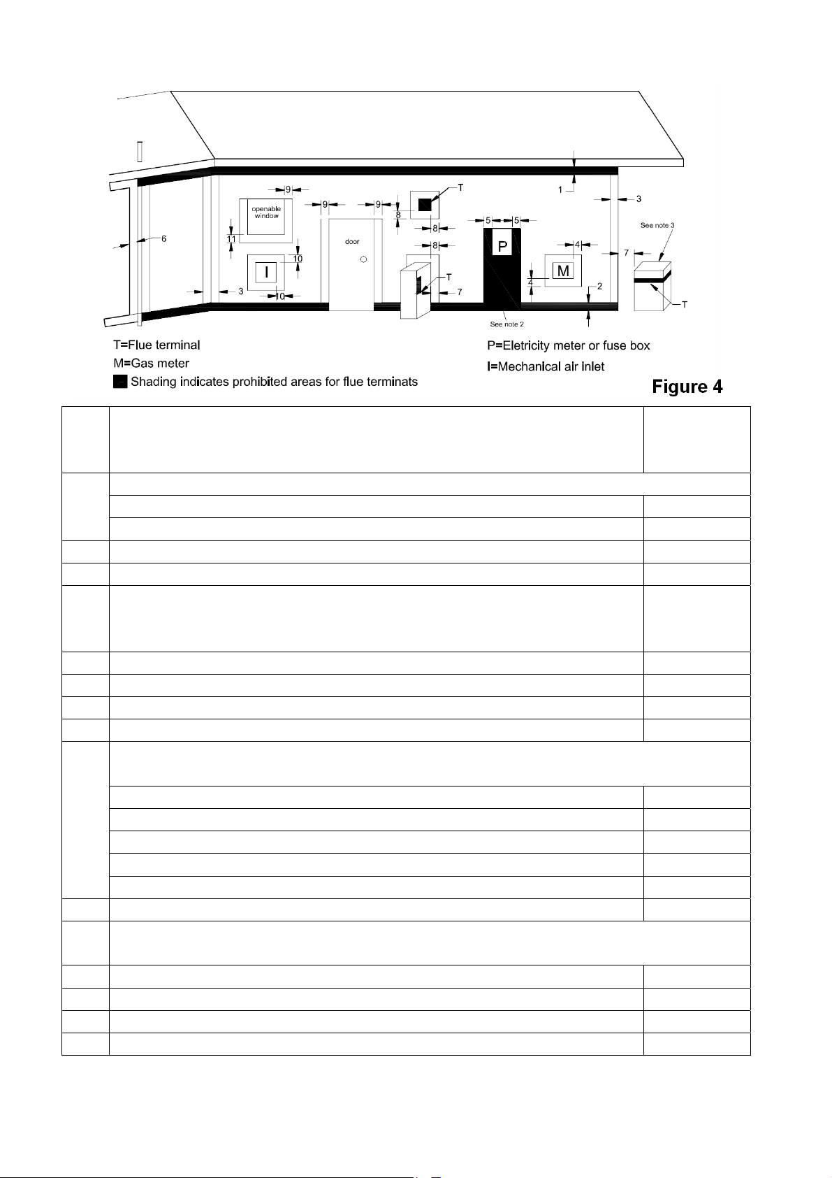
The appliance flue terminal must be located in accordance to Section 6 and Figure 6.2 of AS/NZS 5601. The
requirementsarereproducedandshownonpage7,Figure4.
Note:ReferencestoAS/NZS5601arecurrentatthetimeofprintingbutitistheinstaller’sresponsibilitytoensure
anysubsequentchangesinregulationsareadheredwithinfull.
Theappliancemustbeinstalledclosetothemostfrequentlyusedhotwateroutlettominimisedelaytimeforhot
water delivery. Alternatively, it is possible to strategically install multiple units to provide hot water for several
outletswithminimaldelaytime.ContacttheauthorisedCustomerServiceCentreforfurtherinformation.
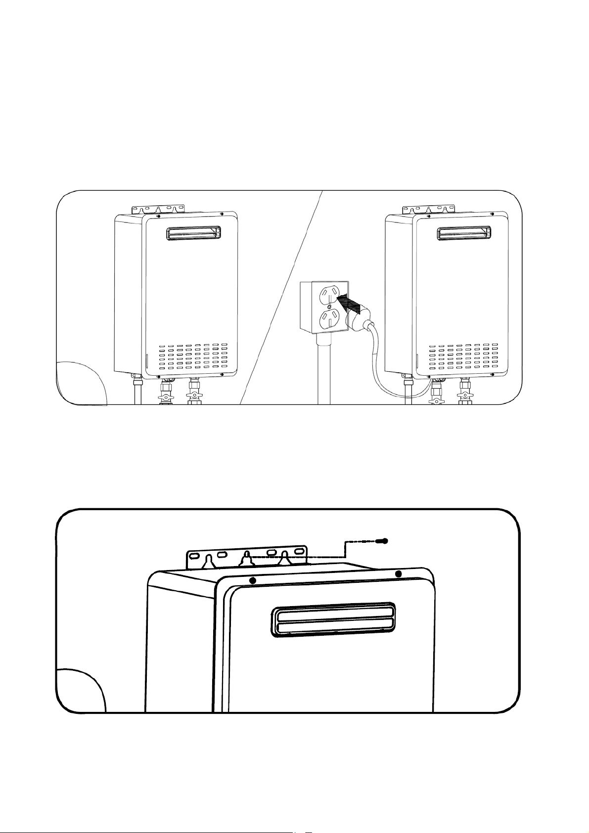
Theunitmustbeinstalledadjacenttoa240Vac,10Amp,earthed,powerpoint.Foroutdoorinstallations,thepower
pointmustbeweatherproof.Thispowerpointmustnotbeinthewayofflueexhaust,waterpressurereliefvalve,or
gas&waterconnectionstotheappliance.
Thelengthoftheappliancepowercordis1.5m.
Theinstalledhotwaterheatermustbeeasilyaccessibleforinspection,servicing,oroperationalpurposes.Sufficient
clearancesareneededtoallowaccessto,orremovalof,allserviceablecomponents.
The unit should not be mounted higher than 2.5m above ground orfloorlevelunlessthecustomercanarrange
permanentandsafeaccesstotheunit.
The water heater should not be installed near an air supply containing halogenated hydrocarbons where
contaminants can be intermixed with non‐polluted air supplying thecombustionprocess.Theaircontaining

Page4
Version1.0Aug2018
halogenated hydrocarbons is safe for human breathing, however when passing through a gas flame, corrosive
elementsarereleasedandwillshortentheoperatinglifeofthegasappliance.
Warrantyisvoidwhenfailureisduetooperationoftheapplianceincorrosiveconditions.
Warning!
Ensurethatthegassupplyisasstatedinproductdatalabel,i.e.naturalgasorLPgas.Powerconnectionand
productinstallationmustbeinaccordancewithmanufacturer’sinstruction&localregulations.
Installationmustonlybecarriedoutbyauthorisedorqualifiedpersonnel.
Thehotwaterheaterisanoutdoorunit,andMUSTNOTbeinstalledindoors.
Theunitmustbeinstalledinalocationwhereitiseasyaccessibleformaintenanceandrepair.
Powerplugandsocketinstallationareashouldbeconsideredwaterprooforfreefromrainsplash.
Theremustbenoelectricalwiringandelectricalappliancesontopofthewaterheater.Distancebetween
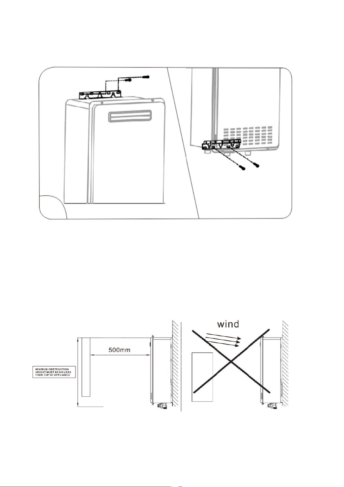
thewaterheaterandelectricalappliancesshouldbemorethan500mmhorizontally.
Distance between water heater and the flammables should be no lessthan150mm.Theexplosiveand
volatileflammables,suchasgasoline,diesel,alcoholetcmustbekeptfarawayfromthewaterheater.
Thewaterheatershouldnotbeinstalledinalocationwhereitcanbeadverselyimpactedbywind.
Iftheinstallationlocationismadeofflammablematerial,metallic heatinsulationshouldbeapplied. The
distancebetweenmetallicinsulationandwallshouldbemorethan10mmandsizeoftheinsulationshould
be100mmlargerthanthegaswaterheater.
Powersupplyforthewaterheateris240Vac,50Hz.Thepowerpointmustbereliablyearthed.
Powersocketshouldbeatlocatedtothesideofthewaterheater,andNEVERtobeundertheunit.
Theapplianceiscontrolledbyintelligentprogrammedelectronicchips.Electromagneticinterferenceshould
bekeptatasafedistancefromtheproduct.
MakesurethehotandcoldwaterconnectionsareNOTreversed;the waterheaterwillnotoperatewith
reversedwaterconnections.
Themanufactureshallnotbeliableforanydirectorindirectdamagecausedbyfaultyinstallation.Theinstaller
mustensurethattheproductinstallationandconnectionscomplywillallregulationsinyourCountry.
Page5
Version1.0Aug2018
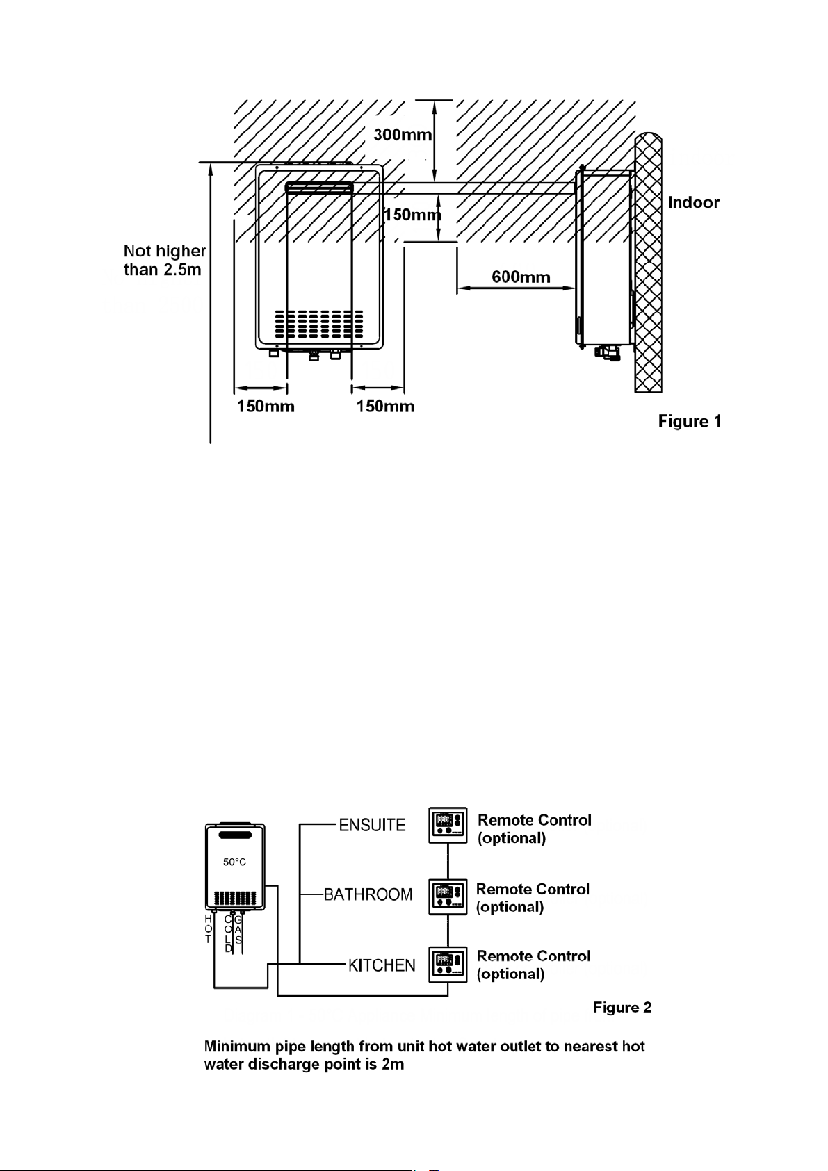
Thegashotwaterheatermustbeinstalledinalocationwithgoodventilation.However,theremustbenowindow
oropeningholes600mminfront,300mmabove,150mmleftand/orright,and150mmlowerthantheunit’sventing
holes to avoid flow of combustion exhaust entering the dwelling. The previously mentioned restricted zones are
shownasshadowinFigure1.
Warning!
Donotinstalltheunitatlocationsubjecttovibrations.
Donotinstalltheunitinarecreationalvehicle,mobilehome,boatorotherwatercraft.
Donotinstalltheunitnearventsforheatingandcoolingwithoutaminimumclearanceof1.2m.
AccordingtoAS/NZS3500,watersuppliedtoareasusedprimarilyforpersonalhygieneislimitedtoamaximumof
50°C.Iftheapplianceispre‐setatthefactorytodeliverwaternotexceeding50°C,localregulationmaypermitits
installation without a temperature limiting device. Installation without a temperature limiting device is shown in
Figure2.Contactthelocalauthoritiestocheckifthereisanuncertainty.
Page6
Version1.0Aug2018
Table1showsthegasconsumptionforeach model.Gaspipesizeisimportantmustbeproperlysizedinorderto
gainthefullperformanceofthehotwaterheater.AnapprovedpipesizechartsuchasthemodelshowninAS/NZS
5601shouldbeconsidered.
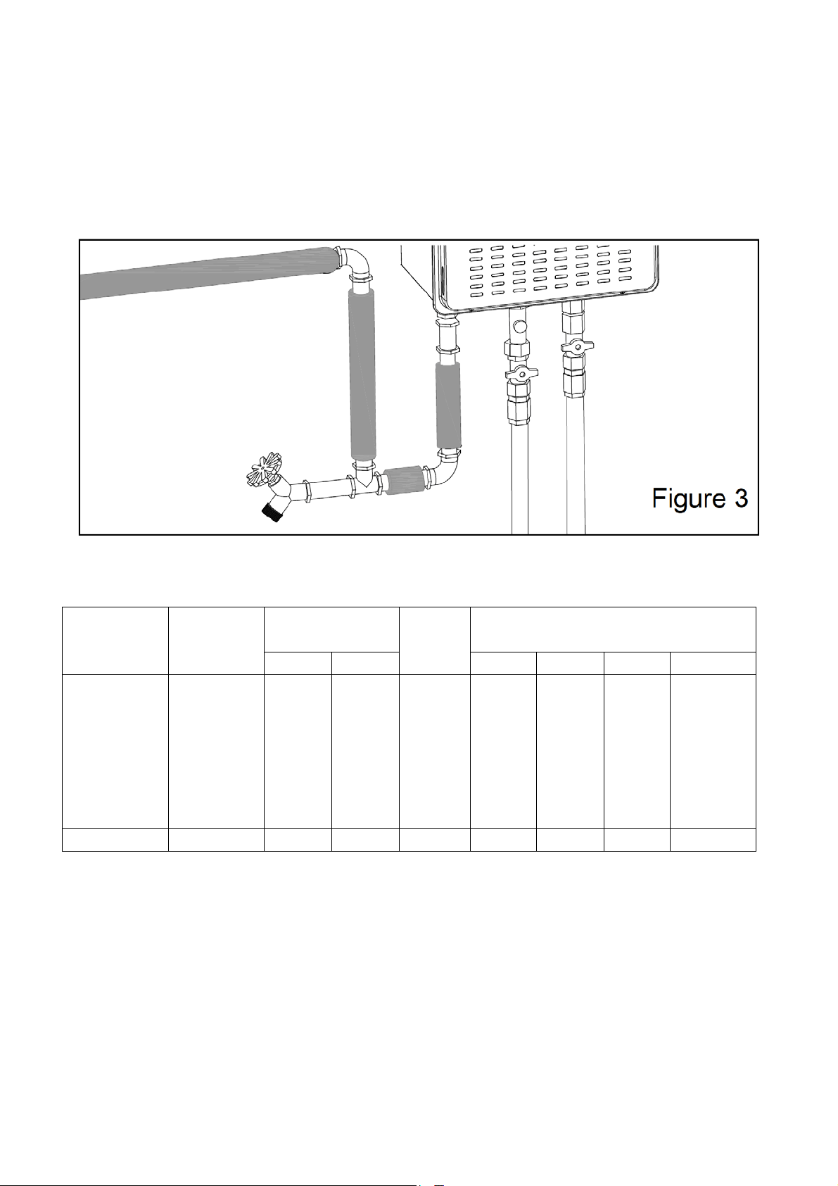
WaterpipesizeandlayoutshouldbeinaccordancewithAS/NZS3500.4.Allhotwaterpipeworkshouldbeinsulated
foroptimalperformanceandenergyefficiency.Waterheaterandwaterlinesshouldbeprotectedfromexposureto
freezingtemperatures–seeFigure3.
Model
Number
Gas
Consumption
(MJ/hr)
WaterSupply
Pressure(kPa)
Weight
(kg)
Fittings
Min. Max. Hot Cold Gas Condensate
ONHW26NG50
/ONHW26LP50
/
ONHW26NG60
/
ONHW26LP60
205 20 1000 19.3 R¾ R¾ R¾ ‐
ONHW30NG60 235 20 1000 21.4 R¾ R¾ R¾ ‐
Table1
Page7
Version1.0Aug2018
Ref Item MinClearance
(Fanassisted)
(mm)
1 Beloweaves,balconiesandotherprojections:
‐ Appliancesupto50MJ/hrinput 200
‐ Appliancesover50MJ/hrinput 300
2 Fromtheground,aboveabalconyorothersurface* 300
3 Fromareturnwallorexternalcorner* 300
4 Fromagasmeter(M)
seeAS/NZS5601Cl.5.11.5.9forventterminallocationofregulator
seeAS/NZS5601Table6.7forNewZealandrequirements
1000
5 Fromanelectricitymeterorfusebox(P)^ 500
6 Fromadrainpipeorsoilpipe 75
7 Horizontallyfromanybuildingstructure*orobstructionfacingaterminal 500
8 Fromanyotherflueterminal,cowl,orcombustionairintake* 300
9 Horizontally from an openable window, door, non‐mechanical air inlet, or any other opening into a
buildingwiththeexceptionofsub‐floorventilation:
‐ Appliancesupto150MJ/hrinput* 300
‐ Appliancesover150MJ/hrinputupto200MJ/hrinput* 300
‐ Appliancesover200MJ/hrinputupto250MJ/hrinput* 500
‐ Appliancesoverto250MJ/hrinput* 1500
‐ Allfan‐assistedappliances,inthedirectionofdischarge 1500
10 Fromamechanicalairinlet,includingaspablower 1000
11 Verticallybelowanopenablewindow,non‐mechanicalairinlet,oranyotheropeningintoabuildingwith
theexceptionofsub‐floorventilation:
‐ Forspaceheatersupto50MJ/hrinput 150
‐ Forotherappliancesupto50MJ/hrinput 500
‐ Forappliancesover50MJ/hrinputandupto150MJ/hrinput 1000
‐ Forappliancesover150MJ/hrinput 1500
*unlessapplianceiscertifiedforcloserinstallation
^prohibitedareabelowelectricitymeterorfuseboxextendstogroundlevel

Page8
Version1.0Aug2018
NOTES:
Wheredimensions3,9or10cannotbeachievedanequivalenthorizontaldistancemeasureddiagonally
fromthenearestdischargepointoftheterminaltotheopeningmaybedeemedbytheTechnicalRegulator
tocomply.
SeeAS/NZS5601Cl6.9.4forrestrictionsonaflueterminalunderacoveredarea.
SeeAS/NZS5601FigureJ3forminimumclearancesrequiredfromaflueterminaltoanLPGascylinder.
Aflueterminalisconsideredtobeasourceofignition.
ForminimumclearancesnotaddressedaboveacceptanceshouldbeobtainedfromtheTechnicalRegulator.
Minimumclearances4and5alsoapplytoanycombustionairintakeopeningsofappliances.
ProductAccessories
The hot water heater comes with the accessories listed below. Please verify the accessories have been supplied
beforeinstallation.
PartsQuantity Remark
Installation&Operatingmanual 1 Keepitproperlyforfuturereference
Expandablescrew 1 Waterheaterinstallation
Wallanchor 6Waterheaterinstallation
Mountingscrew 4 Waterheaterinstallation
RemoteControl(Optional) 1 Modelswithremotecontrol
Remotecontrolcable(Optional) 1 Remotecontrolinstallation
Screw(Optional) 2 Remotecontrolinstallation
Page9
Version1.0Aug2018
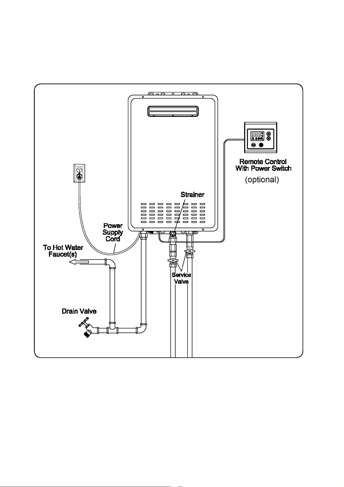
TypicalInstallationofOutdoorHotWaterHeater(NoVentingRequired)
Note:ONSENhotwaterheaterisforoutdoorinstallationONLY
Figure 5
Page10
Version1.0Aug2018
Installation(HotWaterHeater)
Wallreinforcementisrequiredwhenthewallisnotstrongenoughtoholdthewaterheater.Failuretodosocould
resultinpersonalinjuryand/orpropertydamage.
Thewaterheatershouldbeinstalledinapositionwhereitiseasytoaccessandoperate.
Thewaterheaterisdesignedtobeinstalledeitherinsidethewallcavitybetweenwallstudsoroutsidewallcavity.
Makesureaproperlyearthedpoweroutlet(240Vac/50Hz)isavailablebesidetheunit.Thehotwaterheatercomes
witha1.5mlengthpowercord–seeFigure6.
Positiontheuppermountingbracketandpartiallyscrewtheexpandablescrewinplace.Theclearancebetweenthe
screwheadandthewallshouldbeabout3mm.Hangtheupperbracketontothescrew–seeFigure7.
1
Figure 6
Figure 7
2
S
l
o
H
A
f
a
v
d
9
Version1.0A
S
ecuretheto
o
wermounti
H
orizontalO
b
A
S/NZS 5601
a
cing the te
v
erticallyabo
d
oesnotcom
9
.
3
ug2018
pmounting
b
ngbrackett
o
b
structions
stipulates a
rminal. Stru
c
veand belo
w
plywiththis
b
rackettot
h
o
thewallwit
minimum h
o
c
ture with a
n
w
thefront
c
regulationa
n
h
ewallwith
t
htwomoun
t
o
rizontalcle
a
n
area and
s
c
overisacce
n
dmayresul
t
womountin
g
t
ingscrewsa
s
a
rance of 50
0
s
hape that
c
ptable. Stru
c
tintheheat
e
g
screws,an
d
s
showninFi
g
0
mm betwe
e
c
ould cover
t
c
tureonlyp
a
e
rfailingto
o
d
uponcom
p
g
ure8.
e
n a buildin
g
t
he whole a
p
a
rtiallyobstr
u
o
perateinwi
n
p
letingthist
a
g
structurea
n
p
pliance cas
i
u
ctingthe a
p
n
dyconditio
n
Figure
Fig
u
Page
a
sk,securet
h
n
d obstructi
o
i
ng, or exte
n
p
pliancecasi
n
n
s–seeFigu
8
u
re 9
11
h
e
o
n
n
d
n
g
re

Page12
Version1.0Aug2018
WaterSupply
RefertoTable1,Page6,forwatersupplypressurerequirements. An approved pressure limiting valve may be
requiredifthemaximumwaterpressureexceedsthefigureshowninTable1.Inordertoobtainedoptimalhotwater
flow, minimum water supplypressurestatedinTable 1 mustbemet.Thehotwaterheatermayoperateatlower
pressure,howeverratedflowmaynotbeachieved.ContactONSENforgravityfedorlowpressureinstallations.
WatersupplyinmostcitieswillmeetthewaterqualityrequirementsasshowninTable2.Ifyouareunsureabout
yourlocalwaterquality,contactthewaterauthority.Ifsludgeorforeignobjectsarepresentinthewatersupply,a
suitablefilterorstrainershouldbeincorporatedinthewatersupplytowaterheater.
The water heater MUST ONLY be used in the following water supply conditions to prevent product damage and
operationfailure.
Clean,potablewaterfreefromcorrosivechemicals,sand,grit,andothercontaminants.
Inletwatertemperatureabove1°C,butnotexceeding48°C.
DoNOTreverseHOTandCOLDwaterconnections.
DoNOTconnectthiswaterheatertowaterlinespreviouslyused for space heating. All water piping and
componentsshallbesuitableforpotablewaterlines.
WithrecommendedwaterqualityasshowninTable2.
pH TDS
(Total
Dissolved
Solids)
Free
Carbon
Dioxide
(CO2)
Tota l
Hardness
Aluminium Chlorides Copper Iron Manganese Zinc
6.5 ‐
8.5
Up to
500mg/L
Up to
15mg/L
Up to
200mg/L
Up to
0.2mg/L
Up to
200mg/L
Up to
1.0mg/L
Up to
0.3mg/L
Up to
0.05mg/L
Up to
1.0mg/L
Table2
Page13
Version1.0Aug2018
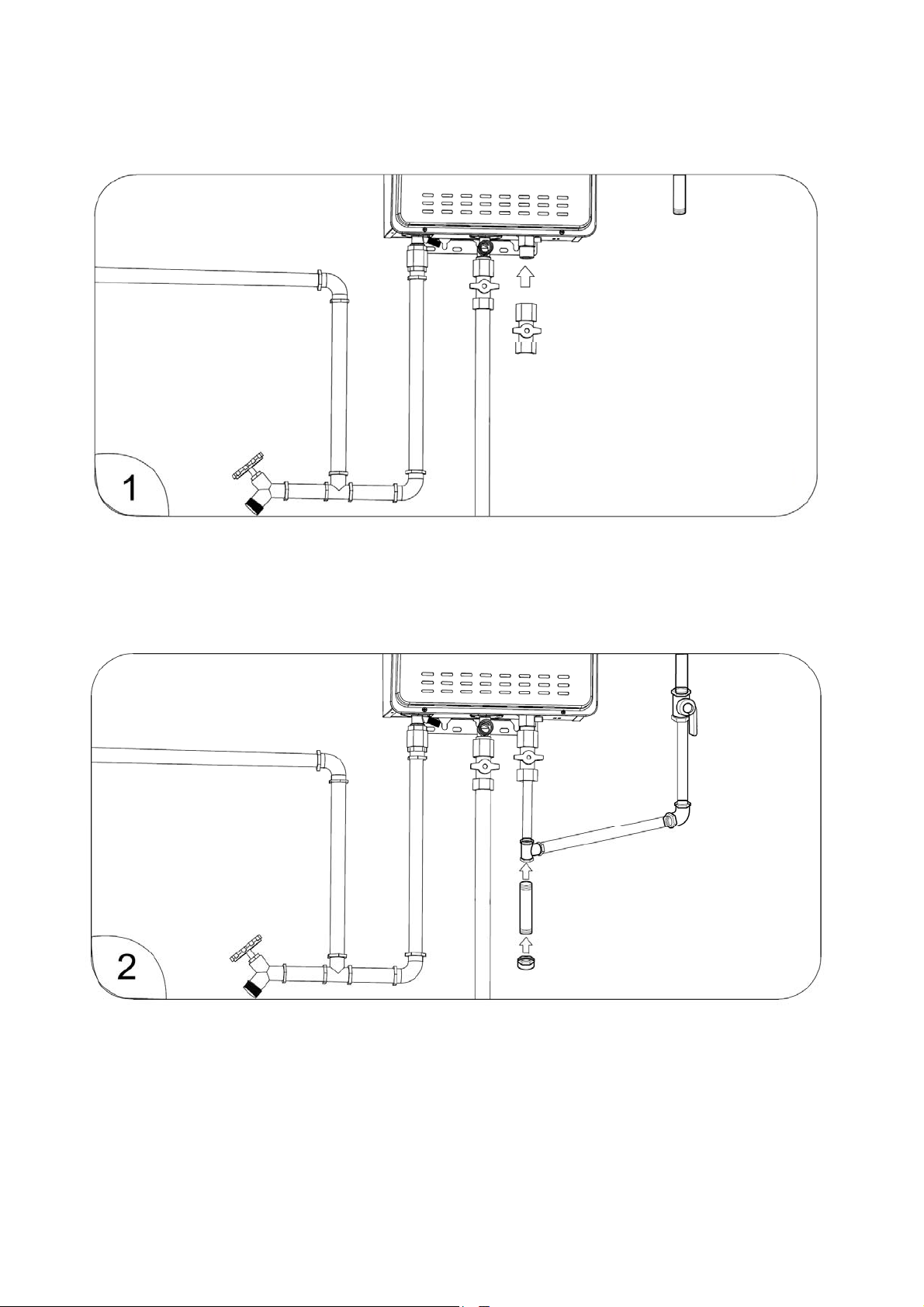
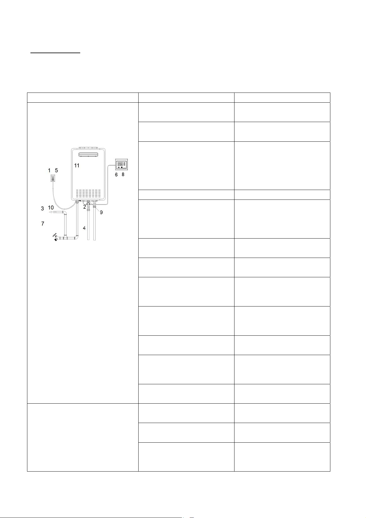
Installation(WaterSupplyLines)
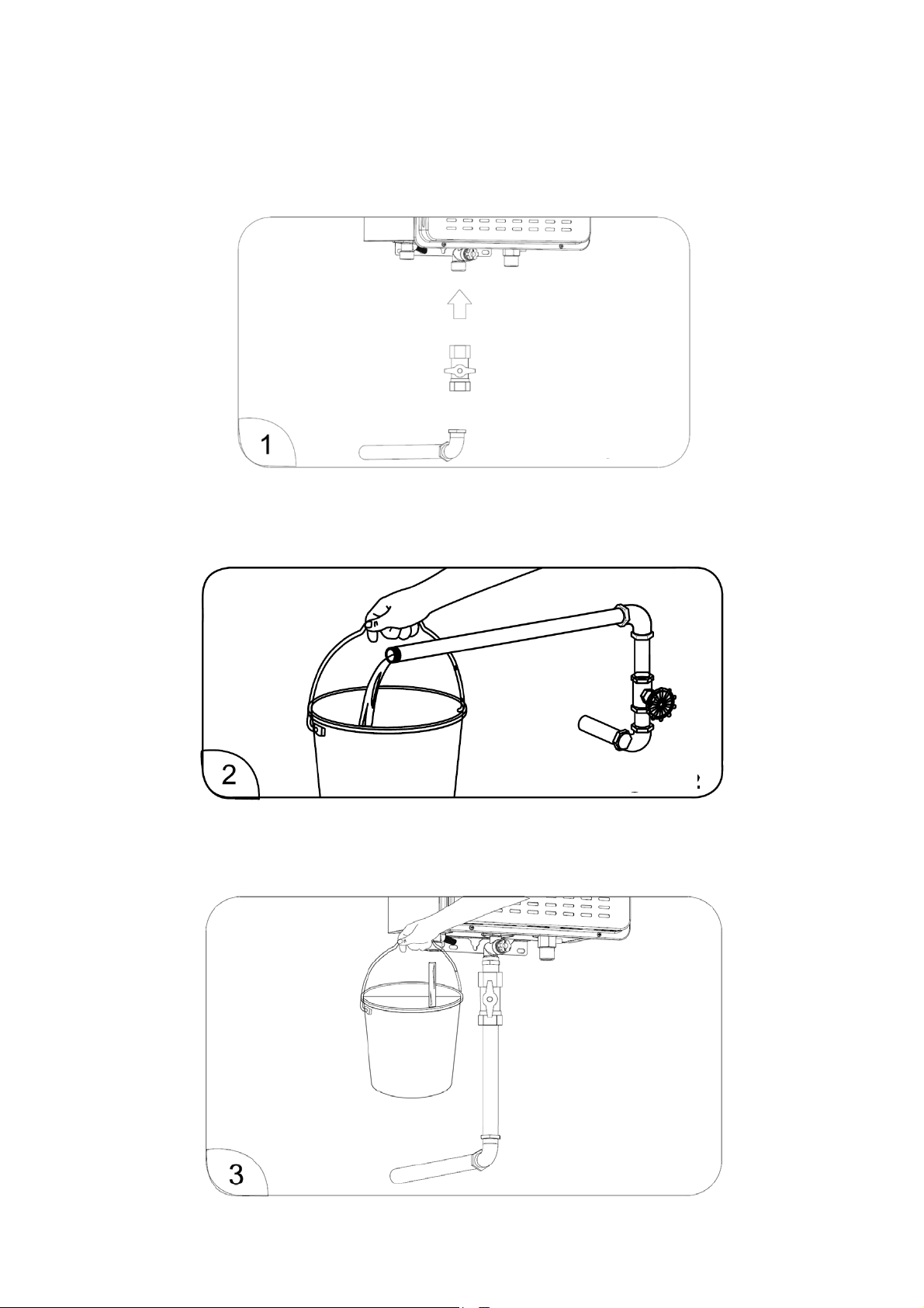
InstalltheservicevalveattheColdwaterinletporttotheheater.Thisvalveisusedwhenservicinganddrainingthe
unit–seeFigure10.
Thewaterpipingsupplyingtheheatershouldbethesamenominalsizeasthewaterheaterfittingsontheunit.
Beforeconnectingtheservicevalvetowaterheater,runwaterthroughthesupplypipetopurgesand,debris,air,
caulking,etc–seeFigure11.
Positionabucketatthewateroutletoftheheaterandopentheservicevalve.Allowthecoldwaterflowthroughthe
waterheaterforapproximately15secondsandclosetheservicevalve–seeFigure12.
Figure 10
Figure 11
Figure 12
Page14
Version1.0Aug2018
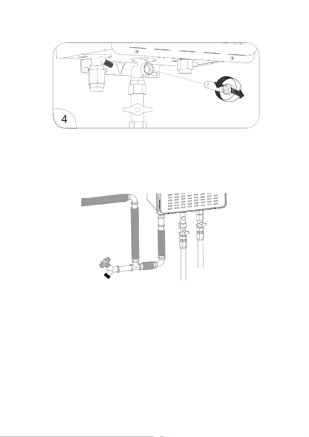
Withtheservicevalveclosed,removethewaterfilter,cleanit,andrefitthefilter–seeFigure13.
Warning!
DoNOTreverseHOTandCOLDwaterconnections.
Theflowrateofhotwatermayvarywhenthereismorethanonewater outletbeingusedatthe sametime.The
pipingmustbecompletelydrainable.Ifanywateroutletislocatedhigherthanthewaterheater,itisrecommended
adrainvalveisinstalledatthelowestpoint–seeFigure14.
UnionconnectionsarerecommendedfortheColdandHotwaterlines.Theseallowwaterheatertobedisconnected
easilyforservicing.
FortheHotwateroutletconnections:
Connectionbetweenwaterheaterandtheclosesthotwateroutletshouldbeasshortaspossiblebutnot
lessthan2metres.
Localcodesshallgovernthepipingusedforwaterconnections.
Forenergyconservationandtopreventfreezing,bothColdandHotwatersupplylinesshouldbeinsulated.
Figure 13
Figure 14
Page15
Version1.0Aug2018
Installation(GasSupplyLines)
Installaservicevalvetothegasinletoftheappliance–seeFigure15.
Usingpropersizepiping,fittings,andcomponentstoconnectthegaslinetothewaterheater.Itisrecommended
thatasedimenttrapbefittedatthelowestpointinthegassupplyline–seeFigure16.
The gas operating limit must NOT exceed 5.0kPa for Natural Gas (NG) or 7.0kPa LP gas. For input adjustment,
minimumgasinletpressure(withmainburneron)isstatedonthewaterheaterdatalabel.Contactyourgassupplier
forcorrectionifgaspressureisoutofthenormalrange.
Figure 15
Figure 16

Page16
Version1.0Aug2018
After the water heater is installed,the appliance and its gas connection, including factory connections, MUST be
leak‐testedatnormaloperatingpressure.
Warning!
NEVERuseanopenflametotestforgasleak!
Turnonthegasservicevalve.
Usesoapywatertotestforleakageatallgasconnectionsandfittings.Ifbubblesareseen,itindicatesthere
isaleakandMUSTberectified–seeFigure17.
HighAltitudeInstallation
Thewaterheaterissuitableforinstallationupto2000ft(600m) above sea level. The input rating of this water
heaterisbasedonsealeveloperation.Athigherelevations,theactualinputratemaybelowerthanthevaluelisted
inproductdatalabel.
For installation above 2000ft (600m) elevation, contact a qualifiedservicetechniciantomakeproperaltitude
adjustments.
Warning!
Do NOT install the water heater at elevations above 2000ft (600m).PleasecontactONSENcustomerservicefor
futureadvice.
HotandColdSupplyLineInsulation
Suitablepipeinsulationand/orelectricheat‐tracingshouldbeusedtopreventwaterinthepipesfromfreezing.
Ifwaterinthepipingisfrozen,thewaterheaterwillmalfunction.
BothHotandColdwaterlinesshouldbeinsulatedforprotectioninareaspronetofreezingconditions–seeFigure
18.
Figure17
Figure 18

Page17
Version1.0Aug2018
PowerConnections
Thepowersupplyusedforthewaterheateris240Vac/50Hz.
Adedicatedcircuitisrecommendedforthewaterheater.DoNOTconnecttoaGFCIorAFCIcircuit.Multipleunits
maybeconnectedtoasinglecircuituptothecircuitrating.
Waitfor90secondsafterpowerisconnectedforthefirsttimetoinitiatewaterheaterprogramandoperation.
ThepowerconsumptionforONSENwaterheater:
Maximumat60Wduringnormaloperation
2Winstandbymode
Upto140Wduringfreezeprotectionfunction
Warning!
DoNOTuse3‐prongto2‐prongadapters.
DoNOTusepowerstripsormultipleoutletadapters.
Fieldwiringconnectionsandelectricalgroundingmustcomplywithlocalcodes&AS/NZS3000.
DoNOTconnectpowerbeforeventinginstallationiscomplete.
Beforeservicingthewaterheater,turnoffthepoweratthemainsbydisconnectingthecircuitbreaker.
Labelallwirespriortodisconnection.
Figure19onpage18showstheelectricalschematicdiagramofthehotwaterheater.
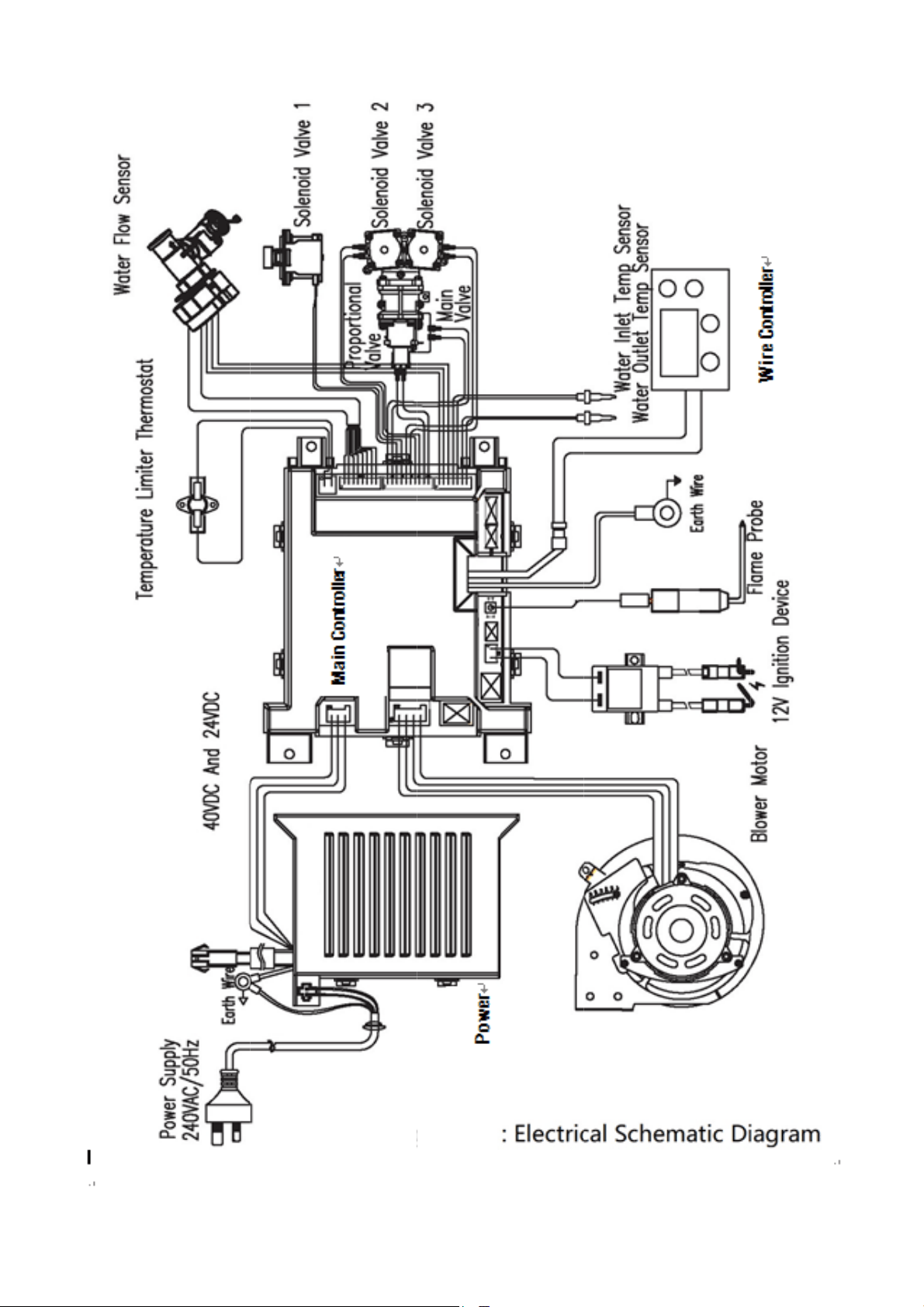
Version1.0Aug2018
Fi
g
g
ure19
Page18

Page19
Version1.0Aug2018
RemoteControlInstallation(ForCertainModelsONLY)
DoNOTinstallremotecontrolinthefollowinglocations:
Outdoor
Areawhichitmayincontactwithwater
Areaexposedtoheat
Areaexposedtosteam
Areaexposedtooil
Areaexposedtodirectsunlight
Areawhereflammableproductsarestoredorused
Remotecontrolshouldbeinstalledoutofchildren’sreachbutinaneasilyaccessiblelocation,e.g.kitchen,laundry
room,utilityroom.
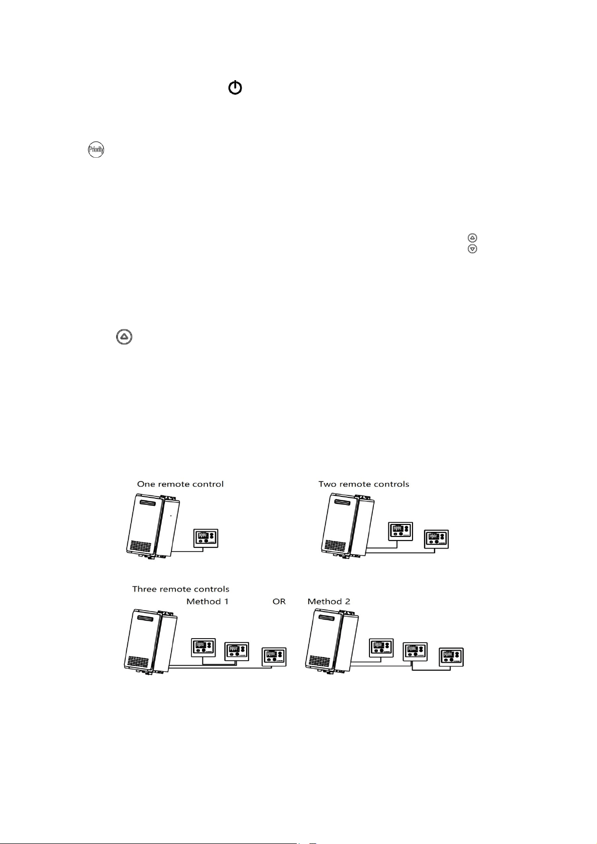
Themaximumdistancebetweenwaterheaterandaremotecontrolis30m,limitedbythewirelengthprovided.
Onewaterheatercanconnectupto3remotecontrolsatatime.
RemotecontrolcablescanbeanyTypeT18AWGwiresimilartoa thermostatwirebutnot sensitivetopolarity.
WiringMSUTNOTbeexposed.DoNOTapplysealanttoremotecontrolcable.DoNOTusenetworkcable,telephone
wire,oranytwistedpaircable.
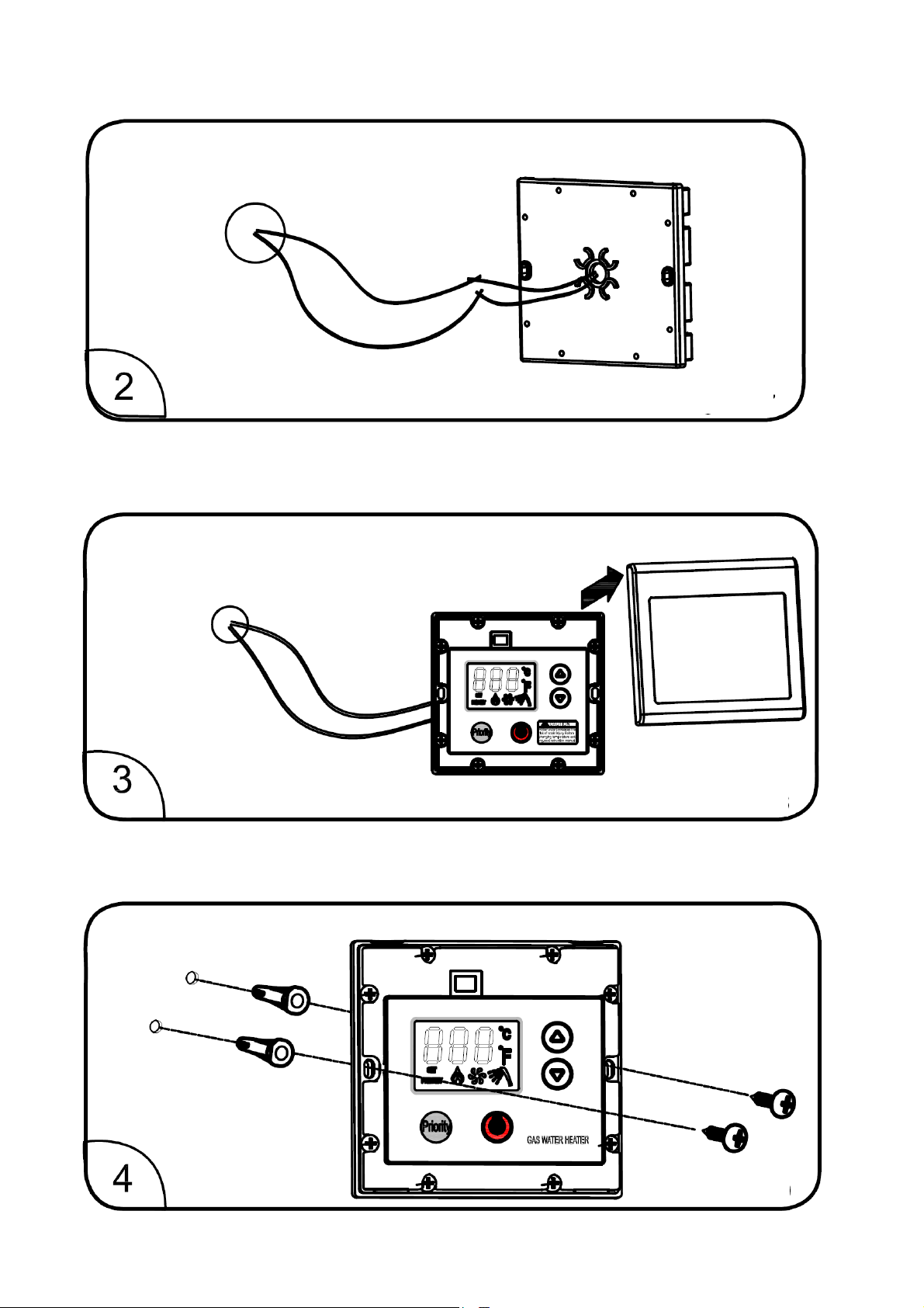
Installation
Drillahole(1to1½inch/2.5‐3.8cm)atthepredeterminedremotecontrolinstallationlocation.Runtheremote
controlcablefromthewaterheatertothehole–seeFigure20.
Figure 20
Page20
Version1.0Aug2018
Connectthecabletotheremotecontrol–seeFigure21
Removethecoveroftheremotecontrol–seeFigure22.
Fixtheremotecontroltothewallbyusingsuitablescrewsandwallanchors–seeFigure23.
Figure21
Figure22
Figure 23
Page21
Version1.0Aug2018
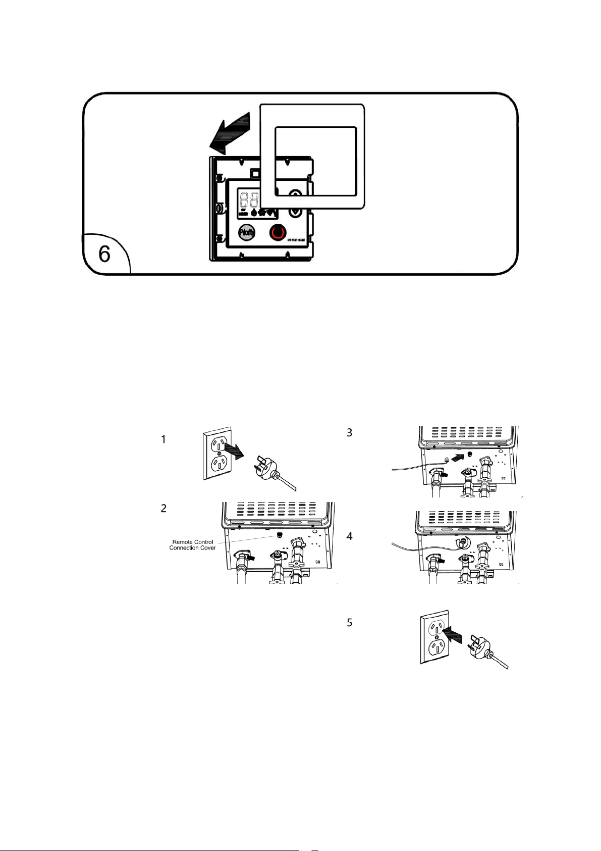
Putthecoverbackontotheremotecontrol.Thetabsonthecovershouldlineupwiththeslotsatthebackofthe
remotecontrol.Securethecovertotheremotecontrolwithonescrewintothebottomtab–seeFigure24.
Warning!
DoNOTattempttoconnecttheremotecontrolorcontrolwirewhile thewaterheaterpowerisON or thewater
heatermaybedamaged.
DoNOTcutorstriptheremotecontrolcablewhileitisconnectedtowaterheaterorwhilethewaterheaterpower
isON.
Connectingtheremotecontroltowaterheater(ForCertainModelsONLY)
Instructions:
1. Ensurethatwaterheaterpowerhasbeendisconnected.
2. Removetheplasticcoverfromremotecontrolconnection
atthebottomofwaterheater.DoNOTremoveFrontPanel.
Thereisnoaccessibleremotecontrolterminalinsidethe
waterheater.
3. Connectthecabletotheconnectionterminal.Theterminals
arenotsensitivetopolarity.
4. Tightentheterminalfirmlybyhand.
5. Connectthewaterheaterpowerplugandcheckiftheremote
controlfunctionsproperly.
6. SeeFigure25.
Figure24
Figure 25

Page22
Version1.0Aug2018
InstallationChecklist
□ Followallinstallationinstructionscoveredinthismanual.
□ Checkthegassupplypressuretomakesureitiswithintherangeasstatedindatalabel.
□ Makesurethereisadequateairforcombustionandventilationasdescribedinthismanual.
□ Maintainproperclearancestocombustiblesandnon‐combustiblesasspecified.
□ Makesureventingsystemcomplieswithlocalcodes.
□ Makesuretheremotecontrolcable(ifany)isproperlyfastenedtothewaterheaterterminal.
□ Makesuretheremotecontrol(ifany)isconnectedinaccordancewithallwiringcodesandregulations
withoutanyexposedconnections.
□ Contactthelocalgascompanytoensuregassupplypressureiswithinlimits.
□ DoNOTblockorrestrictanyoutsideairintakeopenings.
□ Do NOT remove the water heater front cover unless absolutely necessary. This should only be done by
qualifiedpersonnel.
□ Donotinstallthiswaterheaterwheregroundwatermaycollect.
WaterHeaterLocation
□ ONLYtobeinstalledOUTDOORS.
□ Protectedfromfreezingtemperatures.
□ Properclearancefromcombustiblematerialtobeobserved.
□ Sufficientfreshairsupplyforproperoperationofwaterheater.
□ Airsupplyisfreefromcorrosiveelementsandflammablevapours.
□ Sufficientroomtoservicethewaterheater.
□ Combustiblematerialsarenottobekeptneartheheaterandvent.
□ Waterheaterisproperlysecuredtothewall.
WaterSupply
□ Watersupplyhassufficientpressure.
□ Airhasbeenpurgedfromwaterheaterandpiping.
□ Waterconnectionsaretightandleakfree.
□ Waterfilteriscleanandinplace.
□ Waterpipesareinsulatedandprotectedfromfreezing.
GasSupply
□ Gastypematchesthewaterheaterdatalabel.
□ Gassupplypressureissufficientandwithintherangeasstatedinthewaterheaterdatalabel.
□ Gaslineequippedwithaservicevalveandsedimenttrapasdes
cribedintheinstallationinstructions.
□ Approvedpipejointcompoundhasbeenusedonallgaspipeconnections.
□ Allconnectionsandfittingshavebeencheckedforleakswithsoapywater.
PowerConnection
□ Supplycordand/orwiringmeetalllocalcodes,andnationalelectricalcodeAS/NZS3000.
□ Voltagesupplymatchesthelistingindatalabel.
□ Waterheaterisproperlyearthed.

Page23
Version1.0Aug2018
TesttheUnit
□ Purge air andforeignobjectsinthe gas& watersupplylinesbefore connecting the supply lines towater
heater.
□ TurnthegasandwatersuppliesON.Testforleaks.
□ Isolate the gas supply. Remove test point screw located at the gas inlet connection and attach pressure
gauge.
□ Turnonthehotwaterheater&thegassupply.
□ Ifremotecontrolsarefitted,turntheremotecontrolon.Selectmaximumdeliverytemperatureandopen
ALL availablehot water outlets in the house including the shower.Ifremotecontrolisnotfitted,simply
openallavailablehotwateroutlets.(CAUTION:Ensurebuildingoccupantsdonothaveaccesstohotwater
outletsduringthetest)
□ Operateallothergasappliancesattheirmaximumgasrate,inaccordingtotheappliancesmanufacturers’
instructions.
□ Withallgasappliances&hotwaterheateroperatedattheirmaximum gas rate, the gas pressuregauge
shouldreadbetween1.13‐5.0kPaforNaturalGas(NG),andLPGshouldbe2.75–7.0kPa.
□ Ifpressurereadslower,thegassupplyisinadequateandtheapplianceswillnotperformtospecification.If
istheinstaller’sresponsibilitytocheckthegasmeter,serviceregulatorandpipeworkforcorrectoperation
&pipesizeandrectifyasrequired.Thegasregulatorinthehotwaterheateriselectronicallycontrolledand
factorypreset,andundernormalcircumstances,DOESNOTneedadjustmentduringinstallation.
□ Closeallhotwateroutletsincludingtheshower.
□ Inspectandcleanthestrainerlocatedatthewaterheatercoldwaterinletconnection.Thisproceduremay
needtoberepeatedtoensurethestrainerremainsclean,especiallyatasiteofanewdwelling.
□ Ifremotecontrolisfitted,itisnecessarytotesttheallfunctions&operationsoftheremotecontrol.
□ Confirm the hot water heater delivery temperature by using a thermometer. If remote control is fitted,
ensuretemperatureexceeding50°Ccannotbeselectedatbathroomoren‐suiteremotecontrol.
□ Afteralltestsarecompleted,theinhabitantsof the dwellingshouldbemadeawareof the functions and
operationsofthehotwaterheaterandremotecontrol(iffitted).
□ EnsuretheProductRecordonpage44isfilledinandthisbookletishandedtotheinhabitants.

Page24
Version1.0Aug2018
AbouttheGasWaterHeater
ONSENwaterheatersmodels
ONHW26NG50
ONHW26LP50
ONHW26NG60
ONHW26LP60
ONHW30NG60
Thewaterheatersusegasasfuel,andcansupplycontinuousflowofhotwaterforshower,washing,kitchenetc.
ONSENgashotwaterheatersMUSTNOTbeusedforpoolheating.
ONSENhotwaterheatersfeatures
Easytooperate–theoperationsareintelligent,automatic‐controlwiththeadvancedmicrocomputerchips
controllingproportionalvalve,infinitespeed,exhaustfanspeed,andheavyloadcombustiondevice.
Rainproofoutdoorinstallation–thewaterheateritselfisinstalled outdoors, with special hermitical
rainproofstructures.Airforcombustionisextractedfromtheatmosphereandtheexhaustemittedbackto
atmosphere.
Multiple remote controls (optional) – the hot water heater is capableoftakingupto3remotecontrols
installedatdifferent roomsat the same time. Controlling prioritycanbeswitchedamongalltheremote
controls.
Non‐polardoublefrequencysignalcarrierremotecontrol(optional)–theadvancedmethodofsignalcarrier
&communicationisusedbetweenthe remotecontrol and waterheatercontrol board.Theinstallationis
easyandconvenientbyusingnon‐polarandlowvoltagewires.
Automaticerrordetection–whenthehotwaterheaterisinoperation,thecontrolboardwillmonitorthe
workingstateofcontrolcircuits,safetyunits,fan,proportional valve etc. if there is problem, the water
heaterwillstopworking,andanerrorcodewillbedisplayedontheremotecontroliffitted.
Intelligentoxygen‐supply,safetyprotection–toensureacomplete&highlyefficientcombustionprocessis
maintained,themicrocomputerwillautomaticallydetectiftheoxygencontentandairflowissufficient.Fan
speedwillberaisedautomaticallytoavoidincompletecombustionwhenthereisablockagetoguarantee
smoothventilation.Whenthefanspeedreachesacertainpoint(CO boundary), the intelligent Oxygen
supplysafetyprotectionistriggeredandflameisautomaticallyextinguished.
Microcomputersmartcontrol–themicrocomputerinthewaterheaterwillworkouttheperfectworking
parameters to ensure constant hot water temperature delivery based on input data such as inlet water
temperature,presettemperatureetc.
Digitalcontroltemperature–realtimetemperatureismonitoredbyasensorprobeandprovidesfeedback
tomicrocomputer.Anautomaticadjustmentofgasandairsupplyismaintainedaccordingtofeedbackdata
toensureaconstanttemperatureofthewaterdelivery.
Highenergyefficiency–thewaterheatermicrocomputernotonlypreciselycontrolstheamountofsupply
gasthroughgasregulator,italsoadjuststheamountofairneededforcompletecombustion.ONSENwater
heatershavetwobuilt‐infunctions(intensifiedcombustionandforcedheattransfer)thatallowthewater
heaterratedefficiencytobehigherthannationalstandardrequirements.

Page25
Version1.0Aug2018
Lowstart‐upwaterpressure–theminimumworkingwaterpressurecanbeaslowas0.02MPawithan
approximateflowrateof3Lpmwhichisidealforregionswithlowwaterpressure.
Artificial intelligent & power off memory function – when the water heater is restarted, the last
temperaturesettingwillberecalled.
Multiple safety protections – automaticerror detector, flame failuredevice, dual gasvalve safety device,
strong wind pressure protection, incomplete combustion detection, delay ignition cleaning system, over
heatprotection,antifrozenprotection(antifreezingmodelsonly)
Page26
Version1.0Aug2018
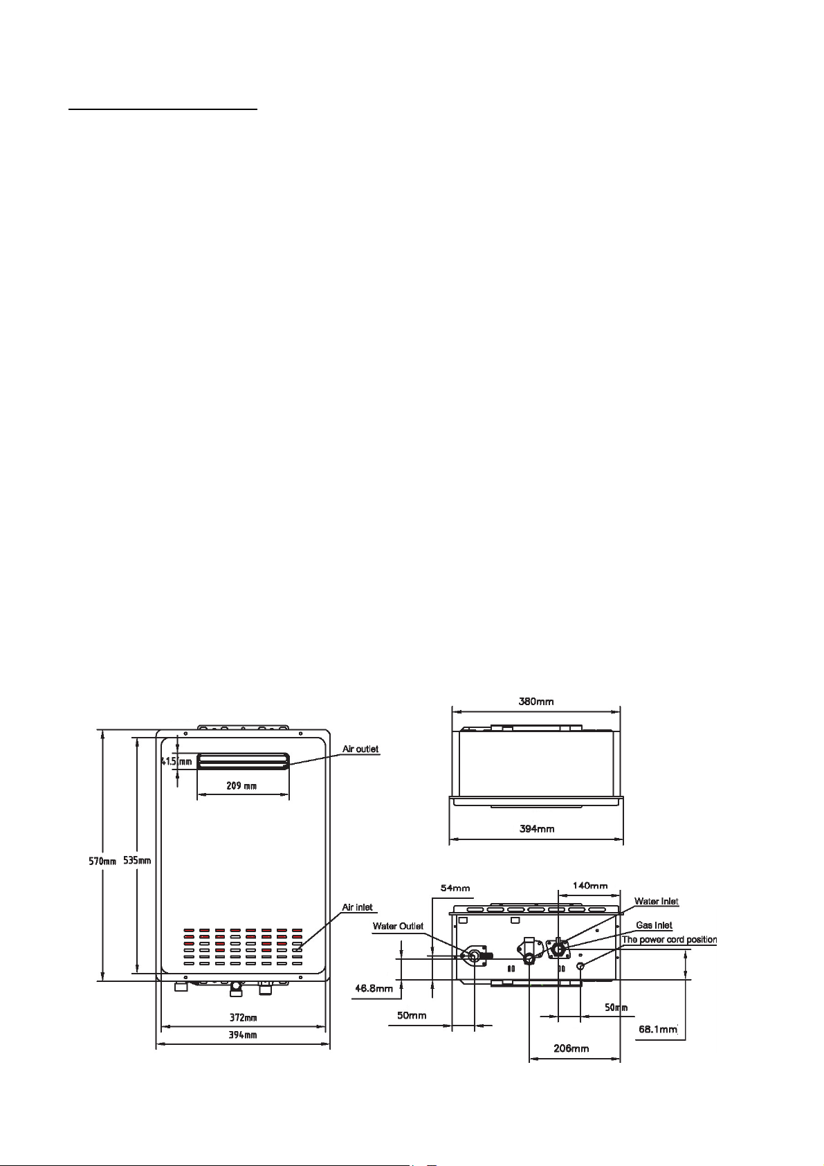
TechnicalSpecifications
Product:ONHW26NG50
Voltage:240Vac/50Hz
Installation:OutdoorONLY
Capacity:26Lpm(25°Candabove),14Lpm(45°Candabove)
Gastype:NaturalGas(NG)
RemoteControl:No
Min/MaxGasSupplyPressure :1.13–5.0kPa
MainInjector(mm):1.47/0.75
Min/MaxGasConsumption :20‐205MJ/hr
Min/MaxTempSetting:37–60°C
FactoryPresetTemp:50°C
Efficiency:84%
EnergyStarRating:6
Min/MaxWaterSupplyPressure :0.02–1.0MPa
IgnitionSystem:Watercontrolled,fullautomaticpulsedischargeignition
WaterTempControl:Intelligentautomaticcontrol
GasValveCertifiedTemp :‐20–70°C
WaterValveCertifiedTemp :0–80°C
ControlBoardCertifiedTemp :‐20–65°C
CombustionFanCaseCertifiedTemp :<105°C
IPRating:IPX4
Dimensions:570x394x166mm
NetWeight:19.3kg
Figure 26
Page27
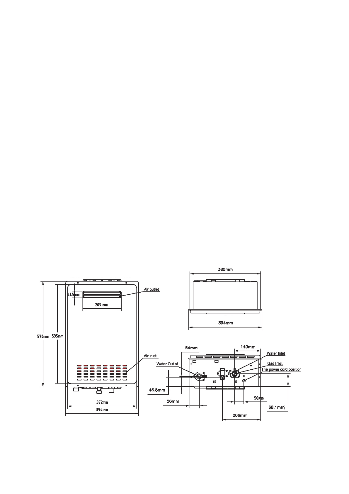
Version1.0Aug2018
Product:ONHW26LP50
Voltage:240Vac/50Hz
Installation:OutdoorONLY
Capacity:26Lpm(25°Candabove),14Lpm(45°Candabove)
Gastype:Propane(LPG)
RemoteControl:No
Min/MaxGasSupplyPressure :2.75–7.0kPa
MainInjector(mm):1.13/0.55
Min/MaxGasConsumption :20‐205MJ/hr
Min/MaxTempSetting:37–60°C
FactoryPresetTemp:50°C
Efficiency:84%
EnergyStarRating:6
Min/MaxWaterSupplyPressure :0.02–1.0MPa
IgnitionSystem:Watercontrolled,fullautomaticpulsedischargeignition
WaterTempControl:Intelligentautomaticcontrol
GasValveCertifiedTemp :‐20–70°C
WaterValveCertifiedTemp :0–80°C
ControlBoardCertifiedTemp :‐20–65°C
CombustionFanCaseCertifiedTemp :<105°C
IPRating:IPX4
Dimensions:570x394x166mm
NetWeight:19.3kg
Figure 27
Page28
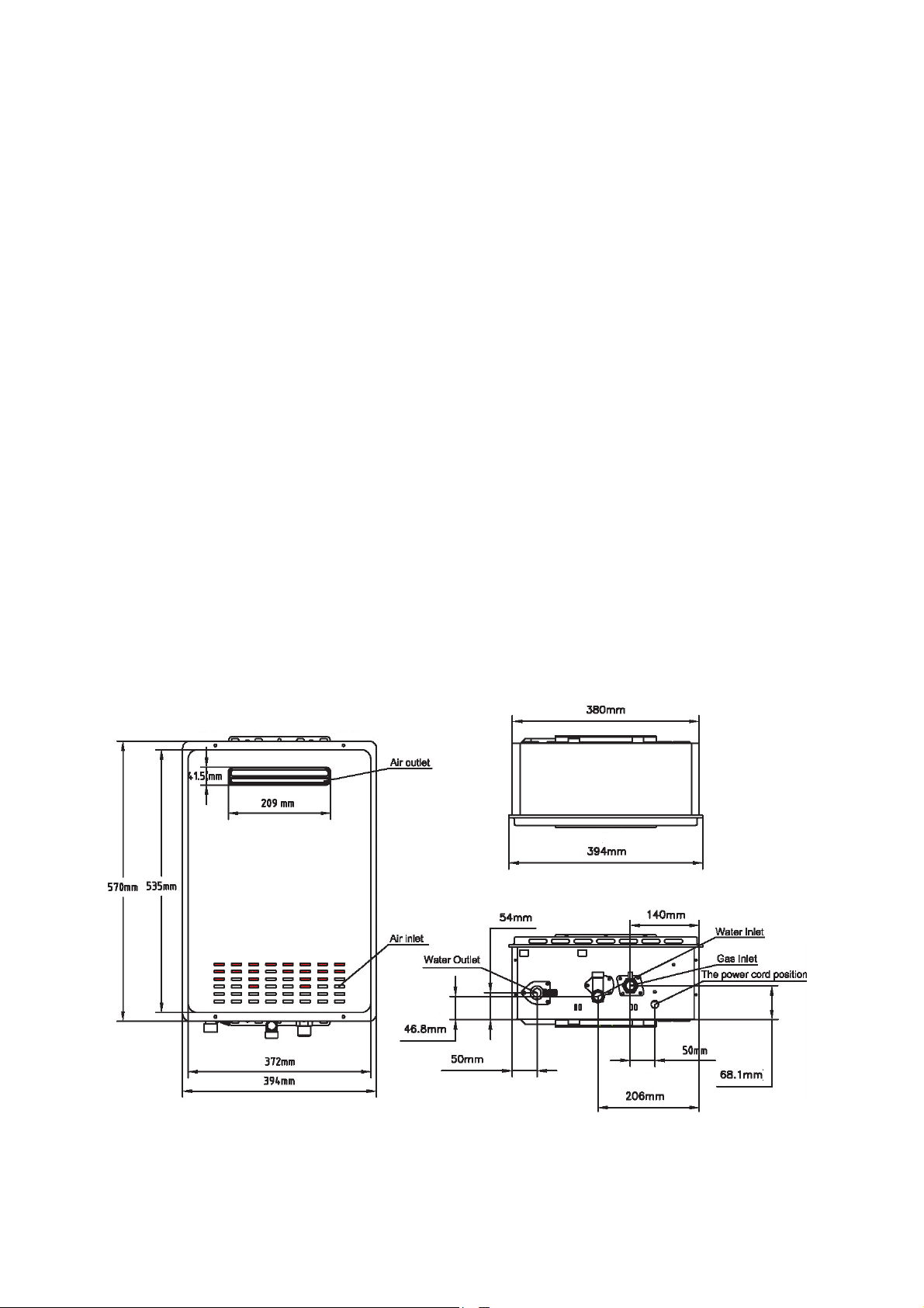
Version1.0Aug2018
Product:ONHW26NG60
Voltage:240Vac/50Hz
Installation:OutdoorONLY
Capacity:26Lpm(25°Candabove),14Lpm(45°Candabove)
Gastype:NaturalGas(NG)
RemoteControl:Yes
Min/MaxGasSupplyPressure :1.13–5.0kPa
MainInjector(mm):1.47/0.75
Min/MaxGasConsumption :20‐205MJ/hr
Min/MaxTempSetting:37–60°C
FactoryPresetTemp:60°C
Efficiency:84%
EnergyStarRating:6
Min/MaxWaterSupplyPressure :0.02–1.0MPa
IgnitionSystem:Watercontrolled,fullautomaticpulsedischargeignition
WaterTempControl:Intelligentautomaticcontrol
GasValveCertifiedTemp :‐20–70°C
WaterValveCertifiedTemp :0–80°C
ControlBoardCertifiedTemp :‐20–65°C
CombustionFanCaseCertifiedTemp :<105°C
IPRating:IPX4
Dimensions:570x394x166mm
NetWeight:19.3kg
Figure 28
Page29
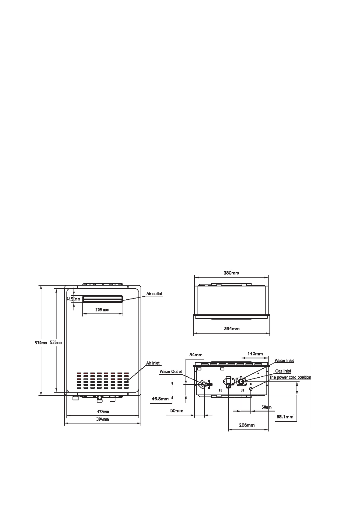
Version1.0Aug2018
Product:ONHW26LP60
Voltage:240Vac/50Hz
Installation:OutdoorONLY
Capacity:26Lpm(25°Candabove),14Lpm(45°Candabove)
Gastype:Propane(LPG)
RemoteControl:Yes
Min/MaxGasSupplyPressure :2.75–7.0kPa
MainInjector(mm):1.13/0.55
Min/MaxGasConsumption :20‐205MJ/hr
Min/MaxTempSetting:37–60°C
FactoryPresetTemp:60°C
Efficiency:84%
EnergyStarRating:6
Min/MaxWaterSupplyPressure :0.02–1.0MPa
IgnitionSystem:Watercontrolled,fullautomaticpulsedischargeignition
WaterTempControl:Intelligentautomaticcontrol
GasValveCertifiedTemp :‐20–70°C
WaterValveCertifiedTemp :0–80°C
ControlBoardCertifiedTemp :‐20–65°C
CombustionFanCaseCertifiedTemp :<105°C
IPRating:IPX4
Dimensions:570x394x166mm
NetWeight:19.3kg
Figure 29
Page30
Version1.0Aug2018
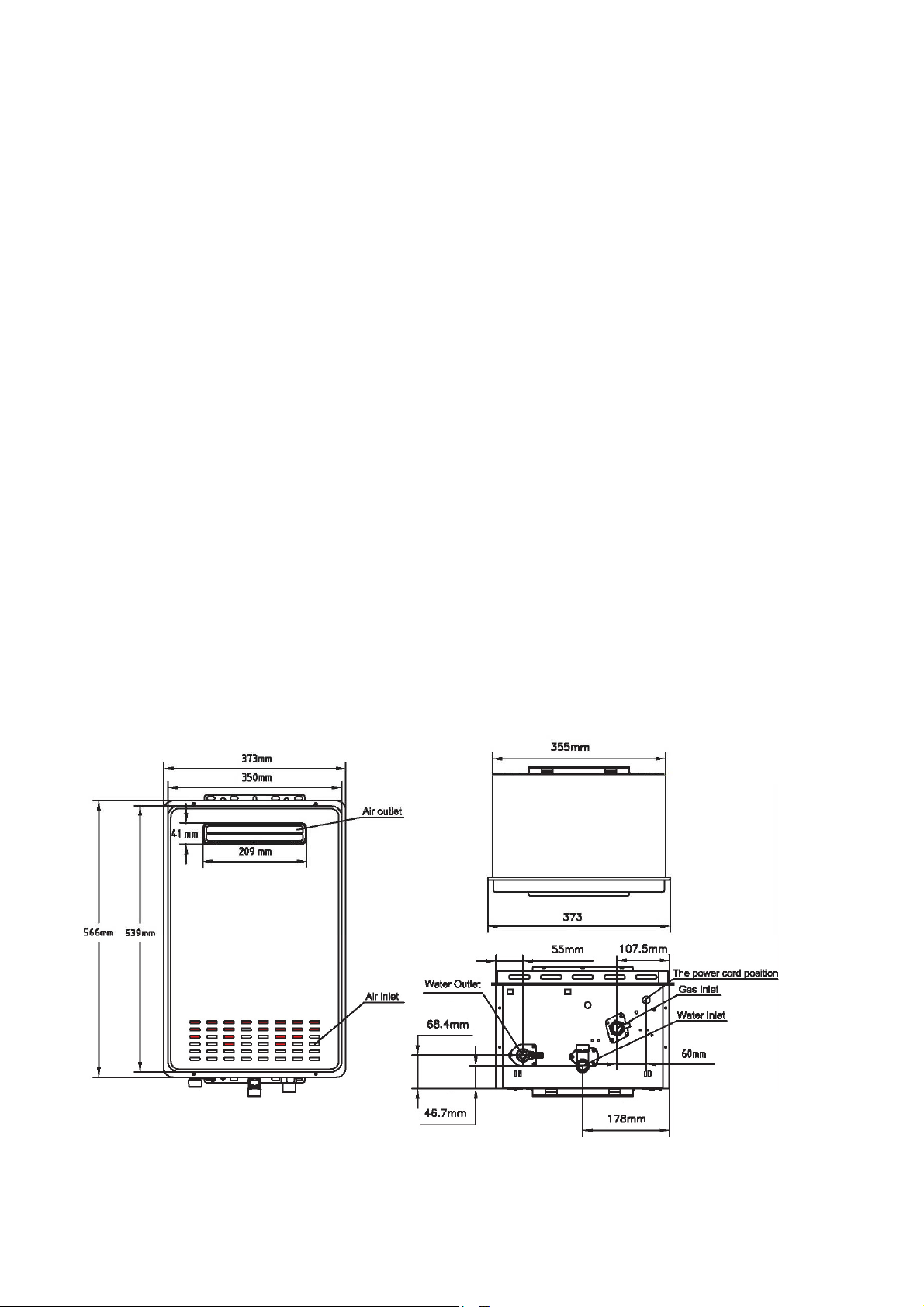
Product:ONHW30NG60
Voltage:240Vac/50Hz
Installation:OutdoorONLY
Capacity:30Lpm(25°Candabove),16Lpm(45°Candabove)
Gastype:NaturalGas(NG)
RemoteControl:Yes
Min/MaxGasSupplyPressure :1.13–5.0kPa
MainInjector(mm):1.55/0.84
Min/MaxGasConsumption :20‐235MJ/hr
Min/MaxTempSetting:37–60°C
FactoryPresetTemp:60°C
Efficiency:84%
EnergyStarRating:6
Min/MaxWaterSupplyPressure :0.02–1.0MPa
IgnitionSystem:Watercontrolled,fullautomaticpulsedischargeignition
WaterTempControl:Intelligentautomaticcontrol
GasValveCertifiedTemp :‐20–70°C
WaterValveCertifiedTemp :0–80°C
ControlBoardCertifiedTemp :‐20–65°C
CombustionFanCaseCertifiedTemp :<105°C
IPRating:IPX4
Dimensions:566x373x240mm
NetWeight:21.4kg
Figure 30

Page31
Version1.0Aug2018
TurnONtheHotWaterHeater
Warning!
Beforeoperatingthehotwaterheater,makesuretoreadandfollowthebelowinstructions,alllabelsonthewater
heater,andthe“ImportantNotes”containedinthisusermanual.
ONSENhotwaterheatersdonothaveapilot.Thehotwaterheaterisequippedwithignitiondevicewhich
automaticallylightsuptheburner.Donottrytolighttheburnerbyhand.
Beforeoperating,smellaroundtheappliancetodetermineifthereisagasleak.Besuretoalsonoteany
smellcomingfromgroundlevelbecausesomegasesareheavierthanairandwillsettleontheground.
Ifyousmellgas,
o DoNOTtrytolightanyappliance.
o DoNOTtouchanyelectricalswitch.
o DoNOTuseaphonewithinthevicinityoftheheater.
o Atasafedistancefromtheheater,immediatelycallyourplumberorgassupplierforadvice.
o DoNOTreturntoyourhomeuntilbeingauthorisedtodosobytheplumberorgassupplier.
DoNOTusethisapplianceiftheinternalshavebeenwetorsubmergedin water. Call a qualified service
techniciantoinspecttheappliancefordamage.
Thetemperaturesettingandthedeliveredwatertemperaturecouldbedifferentduetotheheatdissipated
through pipes and / or seasonal change. It is sound practice tooccasionallymeasuretheactualoutput
watertemperature,particularlyinsystemswhereatemperaturecontrolvalveisinstalled.
Reducewaterdeliveryflowiftheflowexceedsthewaterheaterspecificationtoavoidahotwatershortage.
Increasewaterdeliveryflowifthetemperatureofthedeliveredwaterishigherthanthesettemperature
setting,thismightduetohigherwatersupplytemperature.
ONSENhotwaterheaterwillstopworkingifthehotwaterdeliveryvolumeislowerthan2.5Lpm.
Afteraninstallationoragascylinderchange,allowforafluctuationwithwaterdeliverytemperatureuntil
theairinthegaspipeispurged.
Ifanywateroutletisturnedonbeforethehotwaterheaterispoweredon,thehotwaterheaterwillnot
functionanditwillbeinsafetyprotectionmode.Pleaseturnoffthewateroutletandpoweronthewater
heateragain.
CLOSE mechanical service valve at gas line if the water heater is subjected to overheating fire, flood,
physicaldamage,orifthegassupplyfailstoshutoff.
DoNOTturnonthewaterheaterunlesstheheaterhasuninterruptedwatersupply.
DoNOTturnonthewaterheaterunlesstheheaterhasuninterruptedgassupply.
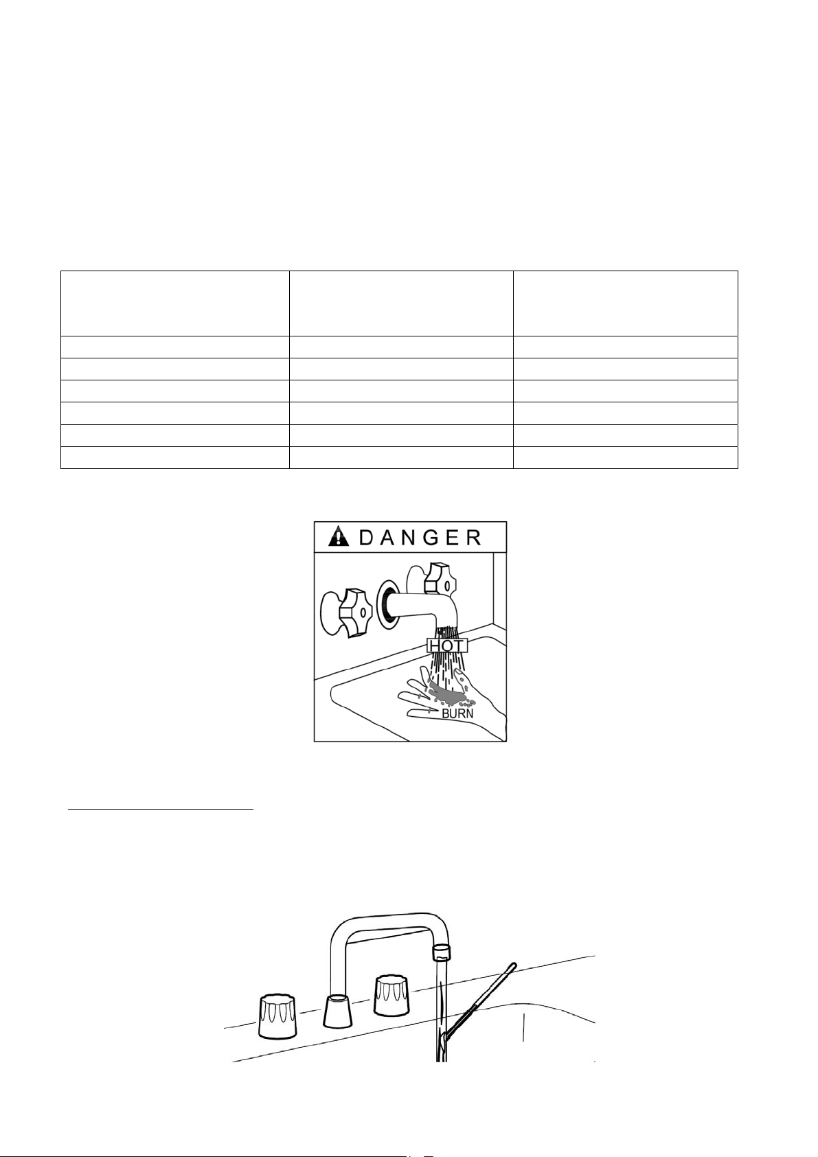
Watertemperaturesabove50°Ccancausesevereburns;suchscaldingmayresultindeath–seeFigure31.
SafetyMUSTbeconsideredwhilesettingthehotwaterdeliverytemperature.Table3showsthataperson
will receive a second degree burn in 3 seconds of exposure and a third degree burn in 5 seconds of
exposuretowaterof60°C.Amaximumtemperatureof50°Catthewateroutletwillensurethemostsafety
forusers.
Children,disabledandelderlyareatmostriskofbeingscalded.
Testdeliverywatertemperaturebeforeshoweringortakingbath.
Page32
Version1.0Aug2018
Activatingthewaterheater:
o Disconnectthewaterheaterpowerplug.
o TurnthegasservicevalveclockwisetotheOFFposition.Thisvalveislocatedontheoutsideofthe
waterheater.Waitfor5minutestoclearanygas.Ifgascan’tbesmelt,proceedtothenextstep.Ifa
gassmellcanbedetected,STOPandrefertoinstructionsonpage31.
o TurnthegasservicevalvecounterclockwisetotheONposition.
o Reconnectandturnonpowersupplytothewaterheater.Thewaterheaterburnerwill
automaticallylightupwhenthereisademandforhotwater.
WaterTemperature(°C) 2ndDegreeBurn
NoIrreversibleDamage
3rdDegreeBurn
FullThicknessInjury
45 2hours 3hours
47 20minutes 45minutes
48 15minutes 20minutes
50 8minutes 10minutes
55 17seconds 30seconds
60 3seconds 5seconds
Table3
SettingWaterTemperature
Maximum water delivery temperature occurs while the water heater burner is ON. To determine the water
temperature,turnonthewateroutletandplaceathermometertomeasurethewaterstream–seeFigure32.Note:
watertemperatureattheoutletmayvarydependingontheweatherandseasonandthelengthofpipefromthe
waterheater.
Figure31
Figure32
Page33
Version1.0Aug2018
Thewaterheatertemperaturerangeisfrom37°Cto60°C.Toadjust the water temperature,refer to the ONSEN
remotecontrolinstructionsonpage34.
Thewaterheatermaynotoperatewithinsufficientwaterflow.Iffullflowatanoutletdoesnotactivatethehot
waterheater,increasethetemperaturesettingofthewaterheaterviaaremotecontrol.
ONSENRemoteControl(ForcertainmodelsONLY)
Warning!
DoNOTtrytodisassembletheremotecontrol.Allcontrolsaresealed and calibrated for accurate control and
operation.
Noothermanufacturer’scontrolsaresuitableforONSENwaterheaters.
Figure 46
Figure 47
Figure 34
Figure 33
Page34
Version1.0Aug2018
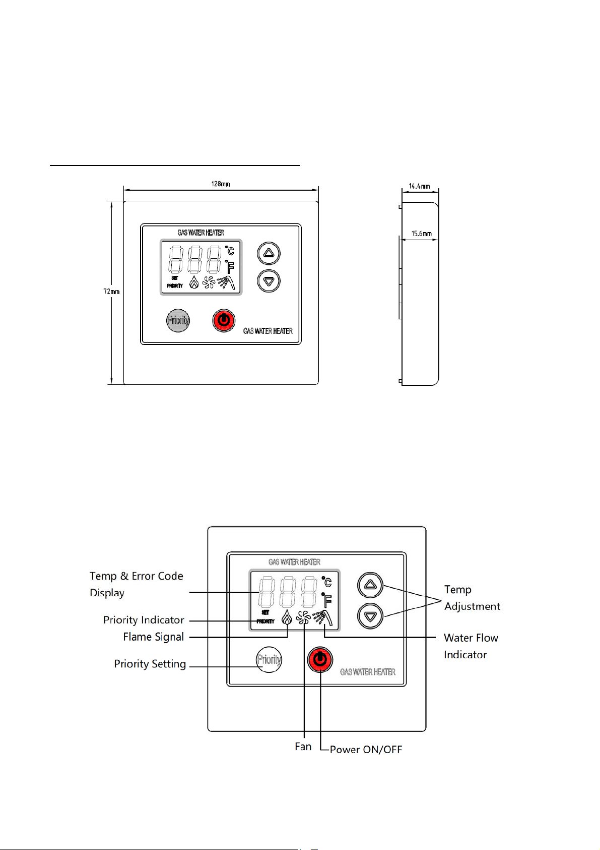
RemoteControlOperation
1. PressthepowerON/OFFbutton once,thedigitaldisplaywilllightupandwillautomaticallyrecallthe
previoussettingfortemperatureoutput.
2. Forwaterheaterinstallationswithmorethanoneremotecontrolinstalled,presstheprioritysettingbutton
oncetoassignprioritystatustothecontroller.Ifsuccessful,thepriorityindicatorwillilluminateand
thecontrollercanbeusedtoadjustthewatertemperaturesetting–seeFigure34.Watertemperaturecan
onlybe adjustedhigherthan48°C withthe hot watersupplyOFF atall outlets. Alwayspressthepriority
buttonbeforeadjustingwatertemperature.Priorityreassignmentcanonlytakeplacewhenthereisnohot
waterdelivery.Refertopoint6inpage35formultiplecontrollerspriorityswitching.
3. Adjust the desired water temperature by using temperature adjustment buttons . Temperature
settingsrangeisfrom37°Cto60°C,withadjustmentsmadein1degreeincrements.
4. Withhotwaterflowing,thetemperatureofthehotwatercannotbeadjustedhigherthan48°C.Toadjust
thetemperaturehigherthan48°C,allhotwateroutletsmustbeshutoffandpresstemperatureadjustment
button .
Note: for ONHW26NG50 & ONHW26LP50, when the hot water heater ispoweredON,thetemperature
setting will default to 50°C. For ONHW26NG60,ONHW26LP60 andONHW30NG60, when the hot water
heaterispoweredON,thetemperaturesettingwillresumeatthepreviousremotecontrolsetting.
5. AsingleONSENwaterheateriscapableofconnectingwithamaximumof3remotecontrolunitsinstalledat
anyonetime.Controllingprioritycanbereassignedtoanyoneoftheremotecontrols.Theinstallationis
parallelconnectionregardlessofpolarityasshowninFigure35.
Figure 35

Page35
Version1.0Aug2018
6. Ifthereismorethanoneremotecontrolinstalled,thefollowingpriorityswitchingoperationsapply:
i. Turnoffhotwaterdeliveryatalloutlets.
ii. WithpowerON,instandbymode,anddisplayOFF,pressONbuttonoftheremotecontroltoassign
itprioritystatus.Thepriorityindicatorwillilluminateandtheremotecontrolcannowadjustwater
temperature.Afterpriorityhasbeenassignedtoaspecificcontroller,theprioritylightonallother
controllerswilldimandtemperatureadjustmentfromthesecontrollersisnotpossible.
iii. With poweredON, in standbymode, anddisplay ON, press anybuttonofanyremotecontrolto
assignitprioritystatus.Thepriorityindicatorwillilluminateandtheremotecontrolcannowadjust
watertemperature.Afterpriorityhasbeenassignedtoaspecificcontroller,theprioritylightonall
othercontrollerswilldimandtemperatureadjustmentfromthesecontrollersisnotpossible.
iv. Whenthewaterheaterisinoperationanddeliveringhotwater,theprioritycannotbereassigned
tootherremotecontrols.Priorityreassignmentcanonlytakeplace when there is no hot water
delivery.
v. WhentheON/OFFbuttonoftheremotecontrolwithpriorityispressed,itwillturnoffthewater
heateraswellasallotherremotecontrols.Thecontrollerwillretainitsprioritywithindicatoron.
vi. To determine the priority and address codes of multiple controllers, turn OFF all controllers and
press and hold for 5seconds until buzzer sounds. The display will now show previous set
address code, or defaultaddress “11”. Press button to set theaddresscodeofeachremote
controlto“12”or“13”.Aftersettingtheaddresscode,pressthepowerbutton orwaitfor3
secondstoautomaticallysaveanyupdatedsettings.Thissettingwillbesavedandremaininplace
evenwhenpoweredoff.PressON/OFFbuttonagaintoexitsetting.
Page36
Version1.0Aug2018
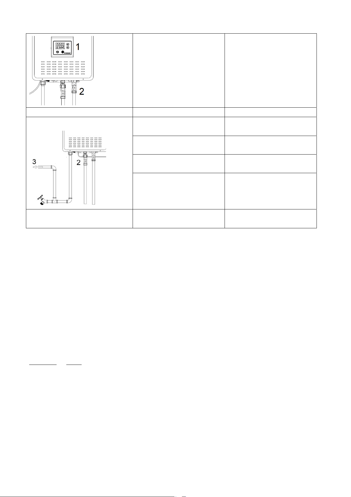
CleaningandMaintenance
Caution:Priortocleaningormaintenance,alwaysdisconnectthepowersupply.
Regularcleaningandmaintenancewillhelptomakesurethewaterheaterisalwaysingoodcondition&prolongthe
working‐lifeofthewaterheater.
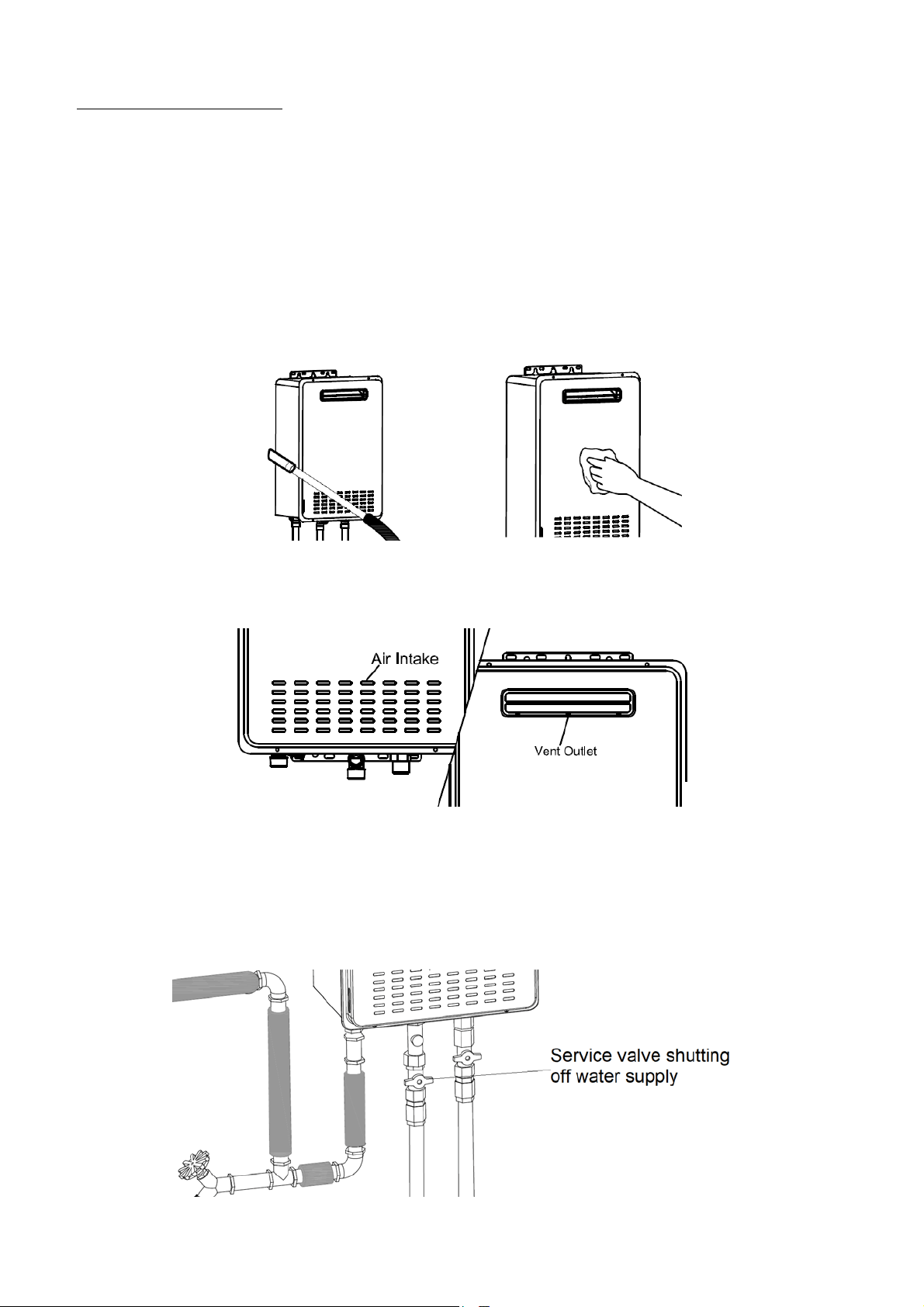
1) CleaningofHotWaterHeater
Ensuretheheaterhasnotbeeninoperationforatleast1hourandthecasingisnothot.Useavacuumcleanerto
cleanaroundthewaterheatertoremoveanydust,dirt,and/orlintbuildup,particularlyneartheairintakeorvent
outlet–seeFigure34.Useadampclothtocleanthehotwaterheatercasing.Drythesurfaceafterwards.Neveruse
grittyorabrasivesponges.Acidicmaterialslikevinegarandcitricjuicesetccandamagethemostresistantsurfaces.
Check the air intake and ventoutlet forblockage and / or debris. The air intake requires a minimum of 300mm
clearancebetweentheairintakeopeningandanyobstruction–seeFigure37.
2) Strainer
Cleanthebuilt‐instraineronamonthlybasistopreventarestrictiontohotwaterflow.Turnoffthewaterheater
anddisconnectthepowerleadfromtheoutlet.Closethecoldwaterservicevalvetoterminatethewatersupplyto
thewaterheater–seeFigure38.
Figure 34
Figure 35
Figure 38
Figure 36
Figure 37
D
U
d
F
R
s
3
T
s
Version1.0A
D
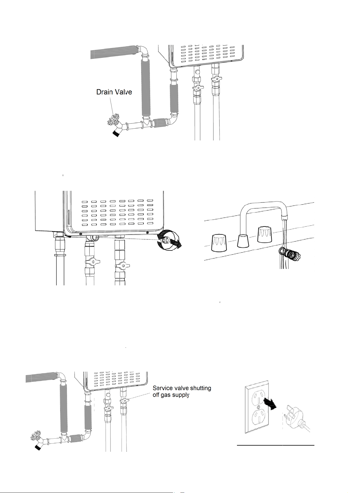
rainthewat
U
nscrew and
d
amagetoth
e
F
igure40.
R
efitthestra
i
ervicevalve.
3
) Draining
T
urnthewat
e
eeFigure41
.
ug2018
erheater.Re
remove th
e
e
strainer.Cl
e
i
nerwhileb
e
Reconnectt
h
theWaterH
e
e
rheaterpo
w
.
fertoinstru
c
e
strainer.D
o
e
anthestrai
n
e
ingcareful
N
h
epowerlea
e
ater
w
erOFF,wai
t
c
tionsofdrai
n
o
notusee
x
n
erunderru
N
OT to over
dandturnt
h
t
for10sec
o
n
ingthewat
e
x
cessive forc
nningwater.
tightenit. T
u
h
ewaterhea
t
o
ndsanddis
c
e
rheater–s
e
e while re
m
Useasoftb
r
u
rnonthe
w
t
eron.
c
onnectpow
e
e
eFigure39.
m
oving it to
a
r
ushtoremo
w
atersupply
b
e
rsuppl
y
.Cl
o
F
Fi
g
a
void defor
m
vesediment
b
yopeningt
o
sethegas
s
F
igure37
Fi
g
Figure
4
g
ure 39
Page
3
m
ation and/
o
andgrit–s
e
hecoldwat
e
s
ervicevalve
g
ure 40
4
1
3
7
o
r
e
e
e
r
–
O
4
C
p
W
I
n
p
i
s
T
Version1.0A
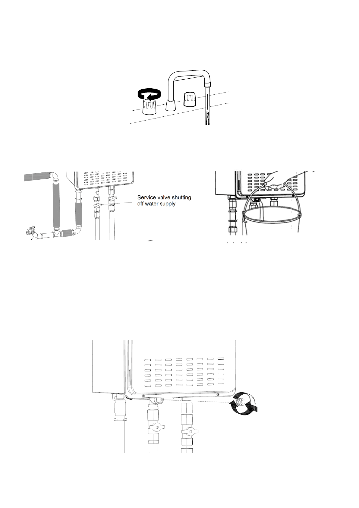
O
penallwat
e
4
2.
C
losethewat
p
ortandhot
w
W
henfullydr
n
coldweat
h
p
rotection30
s
thawed.
T
oputwater
h
ug2018
e
routletsan
d
ersupplyser
v
w
ateroutlet
–
ainedasmal
h
er conditio
n
minutesto
m
h
eaterbacki
d
letthewat
e
v
icevalve.R
e
–
seeFigure
4
lamountof
w
n
s, this rem
m
eltthefroz
nservice,rei
e
rflowuntil
w
e
movethest
r
4
3.
w
aterwillstil
aining wate
r
enwater.O
N
nstallhotwa
w
aterbecom
r
ainerandu
s
lremainint
h
r
canbefro
z
N
SENwater
h
terlineand
s
escold,the
n
s
easuitable
c
h
ewaterhea
t
z
en. If this
h
h
eaterswilln
o
s
trainer–se
e
F
Fi
n
shutoffthe
c
ontainerto
t
er.
h
appens, all
o
o
tworkpro
p
e
Figure44.
F
igure 42
gure 44
wateroutle
t
collectwate
r
o
w the aut
o
p
erlyuntilth
e
Fig
u
Page
3
t
s–seeFigu
r
r
fromstrain
e
o
matic defro
s
e
frozenwat
e
u
re 43
3
8
r
e
e
r
s
t
e
r
Page39
Version1.0Aug2018
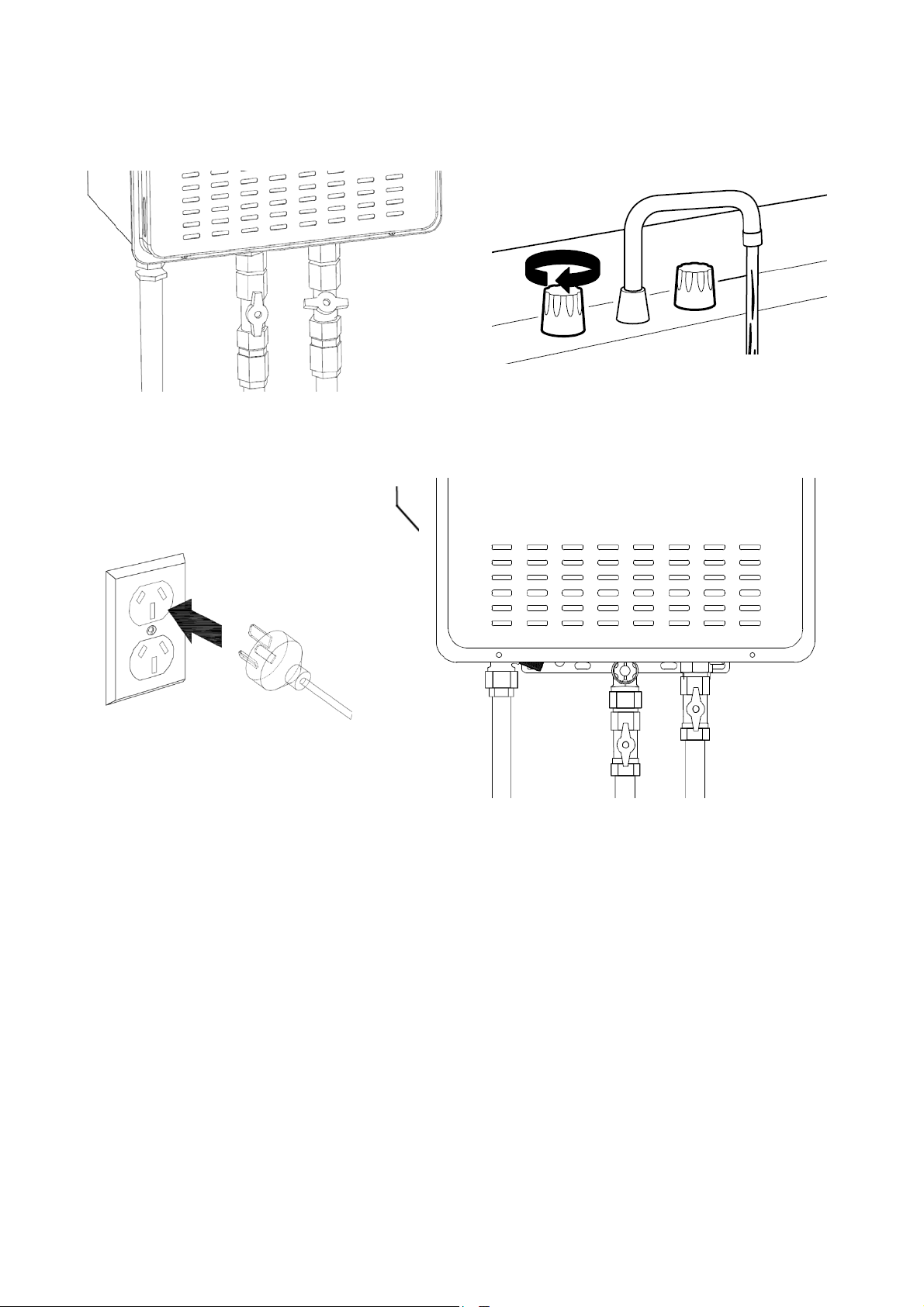
Openthewaterservicevalve.Openallwateroutletsandletwaterruntillairhasbeenpurgedfromwaterlines–
seeFigure45.
Pluginthepowersupply.Openthegasservicevalve.Restartthehotwaterheater–seeFigure46.
4) RegularVisualCheck
Checkandkeepthehotwaterheaterinstallationareacleanandfreefromflammablematerials.Visuallyinspectthe
waterheaterfordamageand/ordenting.Checkforabnormalnoiseduringoperationofwaterheater,e.g.hissing
orbangingnoise.Checkifthereisanyleakageofthewaterorgaslines.Contactaqualifiedplumbertocheckifany
oftheabovementionedarepresent.
5) FreezeProtection
ONSENwaterheaterscomewithfreezeprotectionfunction.Theheatersautomaticallypreventfreezinginsidethe
waterheatertoaslowas‐14°C.Thisfreezeprotectionfunctiononlyprotectstheinternalcomponentsofthewater
heater.
6) VacationandExtendedShutdown
Ifthewaterheatersweretoremainidleforanextendedperiodoftime,thepower,gas,andwatersupplyshouldbe
turned off. The water heater and piping should be drained if they might be subjected to freezing temperatures.
Afteranextendedshutdown,thewaterheateroperationandcontrolsshouldbecheckedbyaqualifiedplumber.
Figure 45
Figure 46
Page40
Version1.0Aug2018
Troubleshooting
Warning!
Foryourownsafety,doNOTtrytorepairtheelectricalwiring,gasandwaterpiping,remotecontrol,burners,vent
connectors,orothersafetydevices.Alwayscontactaqualifiedservicetechnicianifyouhaveanyqueries.
Problem PossibleCauses Solution
Hotwaterflowislowornohotwater
delivery.
1. Hot water heater is not
poweredON.
1. PowerONthehotwaterunit.
2. Water service valve not
completelyopened.
2. Check the service valve and
openitcompletely.
3. Water outlet temperature is
notHOTorflowislow.
3. Increasetheflowatthehot
water outlet. Inadequate
flowwillcausethehotwater
heater burner to turn off
automatically.
4. Waterpipingisfrozen. 4. Allowpipingtothaw.
5. Power is disconnected or
watersupplyisshutoff.
5. a)Reconnectthepowerplug
orcheckthecircuitbreaker.
b) Open the water service
valve.
6. Temperaturesettingofwater
heateristoolow.
6. Increasethewaterheater
temperaturesetting.
7. Water outlet mixing valve
malfunction.
7. Checkandreplacethemixing
valve.
8. Error code display on the
remotecontrol.
8. Refer to “Error Code”
section.Ifrequired,contacta
qualifiedserviceplumber.
9. Waterheaterbuiltinstrainer
iscloggedordirty.
9. Clean the strainer. Refer to
“Cleaning & Maintenance”
section.
10. Water outlet aerator is
cloggedordirty.
10. Cleantheaerator.
11. Scalebuild up at the heat
exchanger.
11. Refer to “Error Code”
section.Ifrequired,contacta
qualifiedserviceplumber.
12. Hot and Cold water lines
connectionsarereversed.
12. Reverse the water line
connections.
Waterisnothotenough. 1. Water heater temperature
settingmaybetoolow.
1. Increasethewaterheater
temperaturesetting.
2. Gas service valve not
completelyopened.
2. Check and open the gas
servicevalvecompletely.
3. Gassupplypressureislow. 3. Contact gas supplier or
contractor to verify gas
meterandgaspipingsize.
Figure 47
Page41
Version1.0Aug2018
Problem PossibleCauses Solution
Watertemperatureistoohot.
1. Water heater temperature
settingistoohigh.
1. Lower the water heater
temperaturesetting.
2. Water service valve is not
completelyopened.
2. Check and open completely
thewaterservicevalve.
3. Wateroutletflowistoolow. 3. Increasethewateroutlet
flowrate.
4. Strainerisblocked. 4. Cleanstrainer.
Fan continues to operate after water
outletisoff.
The post purge cycle is clearing
fluegas.
Normaloperation.
ONSENwaterheaterhasabuilt‐inelectronicdiagnosticsystem.Whenanerroroccurs,theremotecontrolwillshow
theerrorcode.Refertotheerrorcodesfoundbelowandpossiblefaultsforfurtherinformation.
Whenanerrorcodeisshown,turnOFFallhotwateroutlets.TurnOFFthewaterheaterbypressingPowerON/OFF
ontheremotecontrol.Waitforabout5minutes,thenrestartthewaterheateragainbypressingPowerON/OFFon
theremotecontrol.Turnonahotwateroutletandrecheckthedisplaytodetermineifthereisstillanerror.
Iferrorstillexists,turnoffthehotwateroutletandwaterheater.Unplugthepowersupply,waitfor30secondsand
reconnectit.Restartthehotwaterheaterandturnonahotwateroutlettocheckagain.
Ifthereisstillerrorshowninthedisplay,takeanoteofthedisplayederrorandturnOFFthewaterheater.Contact
authorisedservicecentreforservicing.
ErrorCode
Faults
01 Watersupplytemperaturecircuit
10 Flamedetectionmalfunction
11 Ignitionfailure
12 Unexpectedflameout
13 Thermostatcircuiterror
30 Fluepressuresignalinitialdetectionfailure
31 Fluepressurepretestmalfunction
32 Flueblockageerror
34 Pretestmalfuctionforfanblockage
35 Fanblockageerror
Figure 48
Figure 49
Page42
Version1.0Aug2018
40 Fancircuiterror
50 Wateroutletoverheating
51 Waterinletoverhigh
60 Wateroutlettemperaturecircuitmalfunction
70 Programerror
Note:ifthedisplayederrorisnotlistedabove,immediatelyturnoffthewaterheatercancontactauthorisedservice
centre.
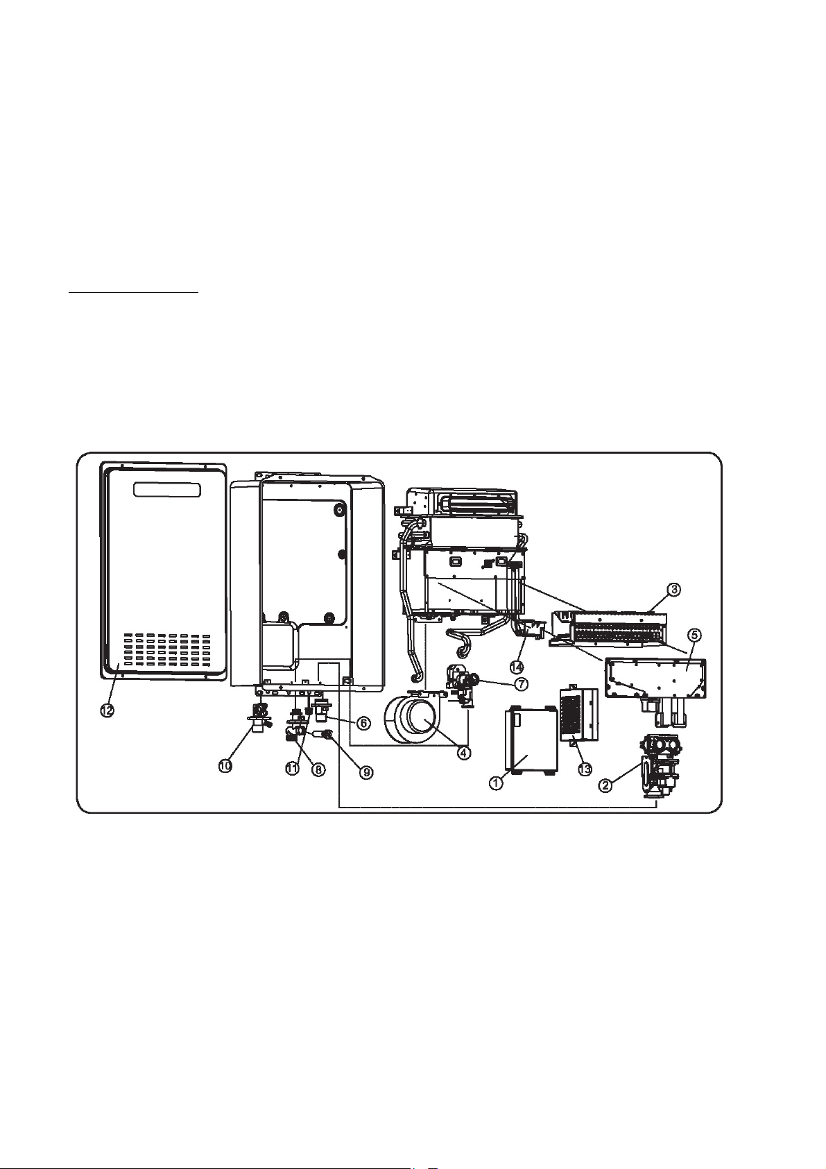
ReplacementParts
Warning!
Alwayscontactaqualified plumber or repairer foranyservicing and repairingjob. Alwayspurchaseoriginal parts
fromONSEN by stating the model number and serial number, specifygastype(LPGorNG),partdescriptionand
numberofpartsdesired.
Formodel:ONHW26NG50/ONHW26LP50/ONHW26NG60/ONHW26LP60
1. Controlboard
2. Gasvalve
3. Burnerassembly
4. Blowermotor
5. Gasmanifold
6. GasinletconnectorR¾
7. Watervalve
8. WaterinletconnectorR¾
9. Strainer
10. HotwateroutletconnectorR¾
11. Remotecontrolterminalblock
Figure 50
Page43
Version1.0Aug2018
12. Frontcover
13. Powerbox
14. Ignitiondevice
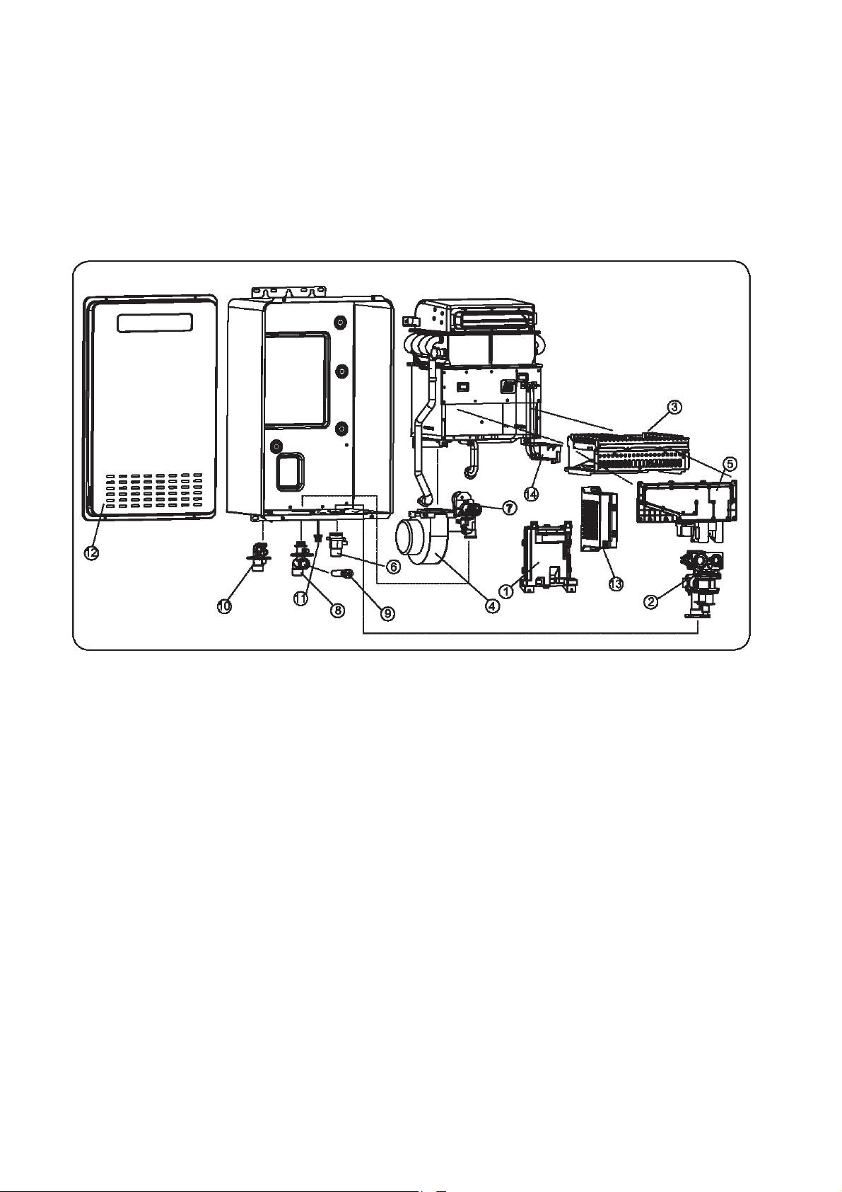
Formodel:ONHW30NG60
1. Controlboard
2. Gasvalve
3. Burnerassembly
4. Blowermotor
5. Gasmanifold
6. GasinletconnectorR¾
7. Watervalve
8. WaterinletconnectorR¾
9. Strainer
10. HotwateroutletconnectorR¾
11. Remotecontrolterminalblock
12. Frontcover
13. Powerbox
14. Ignitiondevice
Figure 51

Page44
Version1.0Aug2018
ProductRecord
CustomerName:_____________________________________________________________________________
MobileNo.:_________________________________________________________________________________
Address:____________________________________________________________________________________
Email:______________________________________________________________________________________
HotWaterHeaterModelPurchased:_____________________________________________________________
UnitSerialNumber:___________________________________________________________________________
PurchasedDate&InstallationDate:______________________________________________________________
PurchaseOrder&Quantity:____________________________________________________________________
InstallationLocation:□Kitchen□Bathroom□Balcony
□Others:__________________________________________________________
Installedby:_________________________________________________________________________________
Signature:__________________________________________________________________________________
Pleasefillinthiscardandkeepitasarecord.

Page45
Version1.0Aug2018
MaintenanceRecord
Maintenance
Date
ErrorDescription RepairDetails Service
Personnel
Signature
House owner
confirmation


