Welcome to Follett
Follett equipment enjoys a well-deserved reputation for excellent performance, long-term reliability and outstanding
after-the-sale support. To ensure that this equipment delivers that same degree of service, review this guide carefully
before you begin your installation.
Should you have need technical help, please call our Technical Service group at (877) 612-5086 or (610) 252-7301.
Please have your model number, serial number and complete and detailed explanation of the problem when
contacting Technical Service.
Getting Started
After uncrating and removing all packing material. Inspect the equipment for concealed shipping damage. All freight
is to be inspected upon delivery. If visible signs of damage exist, please refuse delivery or sign your delivery receipt
"damaged." Follett Customer Service must be notied within 48 hours. Wherever possible, please include detailed
photos of the damage with the original packaging so that we may start the freight claim process.
Installation and Service Videos:
www.follettice.com/servicevideolibrary
01234608R06
801 Church Lane • Easton, PA 18040, USA
Toll free (877) 612-5086 • +1 (610) 252-7301
www.follettice.com
Installation, Operation and Service Manual
After serial number K39863
Please visit https://www.follettice.com/technicaldocuments
for the Operation and Service manual for your unit.
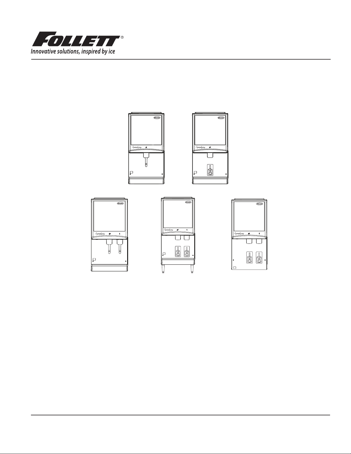
Symphony Plus
™
12 Series
Ice and Water Dispensers
12CI425A, 12HI425A

Contents
Welcome to Follett. . . . . . . . . . . . . . . . . . . . . . . . . . . . . . . . . . . . . . . . . . . . . . . . . . . . . . . . . . . . . . . . . . . . . . . . . . . 3
Before you begin .......................................................................... 3
Specications .............................................................................. 4
Electrical ................................................................................ 4
Ambient ................................................................................. 4
Plumbing ................................................................................ 4
Ventilation clearances ...................................................................... 4
Dry weight ............................................................................... 4
Installation ................................................................................. 5
Before you begin .......................................................................... 5
Installing countertop dispensers without legs .................................................... 5
Installing countertop dispensers with legs accessory (P/N AF10LBLEGS) ............................. 6
Installing wall mount dispensers .............................................................. 6
User information ........................................................................... 11
How the dispenser works ...................................................................11
Panel removal ........................................................................... 12
Cleaning and sanitizing ..................................................................... 13
Weekly ................................................................................ 13
Monthly ................................................................................ 13
Semi-Annually (more often if conditions dictate) ................................................ 14
Ice Machine and Dispenser ................................................................ 14
Service ................................................................................... 16
Ice machine operation (all models) .......................................................... 16
The icemaking process .................................................................... 16
Water system ........................................................................... 17
Electrical system ......................................................................... 18
Wiring diagram .......................................................................... 20
Wiring diagram - Lever only ................................................................ 22
Wiring diagram - SensorSAFE only .......................................................... 23
Ice machine operational and diagnostic sequences ............................................. 24
Diagnostic stages ........................................................................ 29
Refrigeration pressure data ................................................................ 33
Compressor data ........................................................................ 33
Refrigeration system ...................................................................... 33
Dispenser troubleshooting .................................................................. 35
Lever model troubleshooting guide .......................................................... 35
SensorSAFE model troubleshooting guide .................................................... 35
Disassembly and replacement instructions ..................................................... 36
Fan removal ............................................................................ 40
Thermostat and ice transport tube replacement ................................................ 41
Replacement parts ......................................................................... 42
Dispenser exterior ........................................................................ 42
Wheelmotor and drive system .............................................................. 43
Dispense chute and splash panel (models with lever dispensing) .................................. 44
Dispense chute and splash panel (models with SensorSAFE infrared dispensing) ..................... 45
Ice machine components .................................................................. 46
Electrical components .................................................................... 48
Compressor ............................................................................ 49
Evaporator replacement parts .............................................................. 50
Water supply and drains ................................................................... 52
Water treatment accessories for Symphony Plus ice and water dispensers .......................... 53
2 12CI425A, 12HI425A
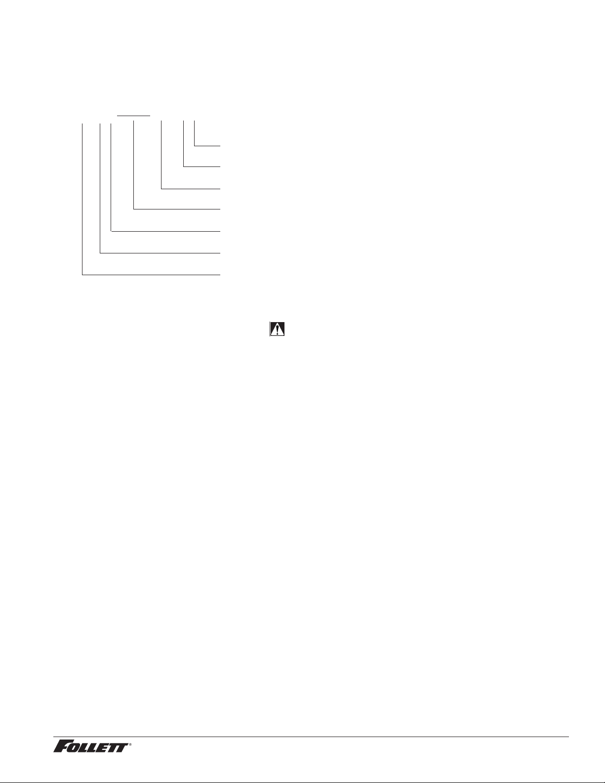
Check your paperwork to determine which model you have. Follett model numbers are designed to provide
information about the type and capacity of Follett ice dispensing equipment. Following is an explanation of the
different model numbers.
12CI425A-LI
I = ice-only; no water
Dispense actuation, L = lever, S = SensorSAFE
Condenser type, A = air-cooled
Ice machine capacity in lbs per day
Ice machine location, I = integral
Dispenser conguration, C = countertop, H = wall mount
Approximate storage capacity in lbs
CAUTION!
§ Do not tilt unit further than 30° off vertical during uncrating or installation.
§ Dispenser bin area contains mechanical, moving parts. Keep hands and arms clear of this area at all times. If
access to this area is required, power to unit must be disconnected rst.
§ Follett recommends a Follett water lter system be installed in the ice machine inlet water line (standard capacity
#00130229, high capacity #00978957, carbonless high capacity #01050442).
§ Prior to operation, clean the dispenser in accordance with instructions found in this manual.
§ Ice is slippery. Be sure counters and oors around dispenser are clean, dry and free of ice.
§ Do not block right side air intake or top air exhaust.
12CI425A, 12HI425A 3
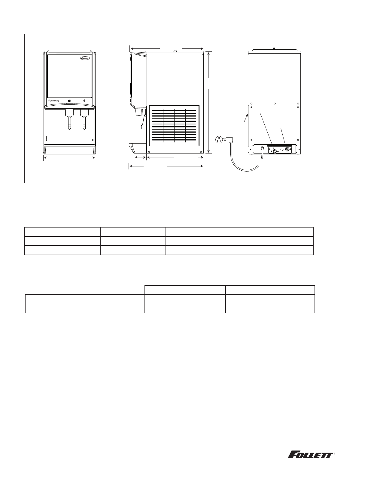
Specications
air exhaust
16.00
"
(40.7 cm)
4.00
"
(10.2 cm)
3/8
" FPT
water inlet
3/4
" MPT drain
23.5
"
(59.7 cm)
18.00
"
(45.8 cm)
32.00
"
(82.6 cm)
air
intake
Front View Side View Rear View
22.625
"
(57.5 cm)
power cord (NEMA 5-15)
Electrical
§ 115 V, 60 Hz, 1 phase, 11.0A
§ Connect to a 15A dedicated circuit.
Ambient
Air temp* 100 F/38 C Max. 50 F/10 C Min. Best performance below 80 F (27 C)
Water temp
†
90 F/32 C Max. 45 F/4 C Min. Best performance below 70 F (21 C)
Water pressure (psi/bar) 70/5 Max. 10/0.7 Min.
* Ambient air temperature is measured at the air-cooled condenser coil inlet.
†
Ambient water temperature is measured in the ice machine reservoir.
Plumbing
12CI425A 12HI425A
Dispenser drain 3/4" MPT 3/4" MPT
Water inlet 3/8" FNPT 3/8" FNPT
Note: Water shut-off recommended within 10 ft. (3 m) of dispenser. Drain to be hard-piped and insulated. Maintain at
least 1/4" per foot (20 mm per 1 m) run of slope.
Ventilation clearances
§ 6" (15.3 cm) on right side of dispenser, 6" (15.3 cm) at top, and 12" (30.5 cm) at top recommended for service.
Note: Do not block right side air intake or top air exhaust.
Dry weight
§ 144 lb (65 kg)
4 12CI425A, 12HI425A
* Dow Corning is a registered trademark of Dow Corning Corporation in the United States and other countries.
Refrigeration system
Important: All service on refrigeration system must be performed in accordance with all federal, state and
local laws that pertain to the use of refrigerants. It is the responsibility of the technician to ensure that these
requirements are met.
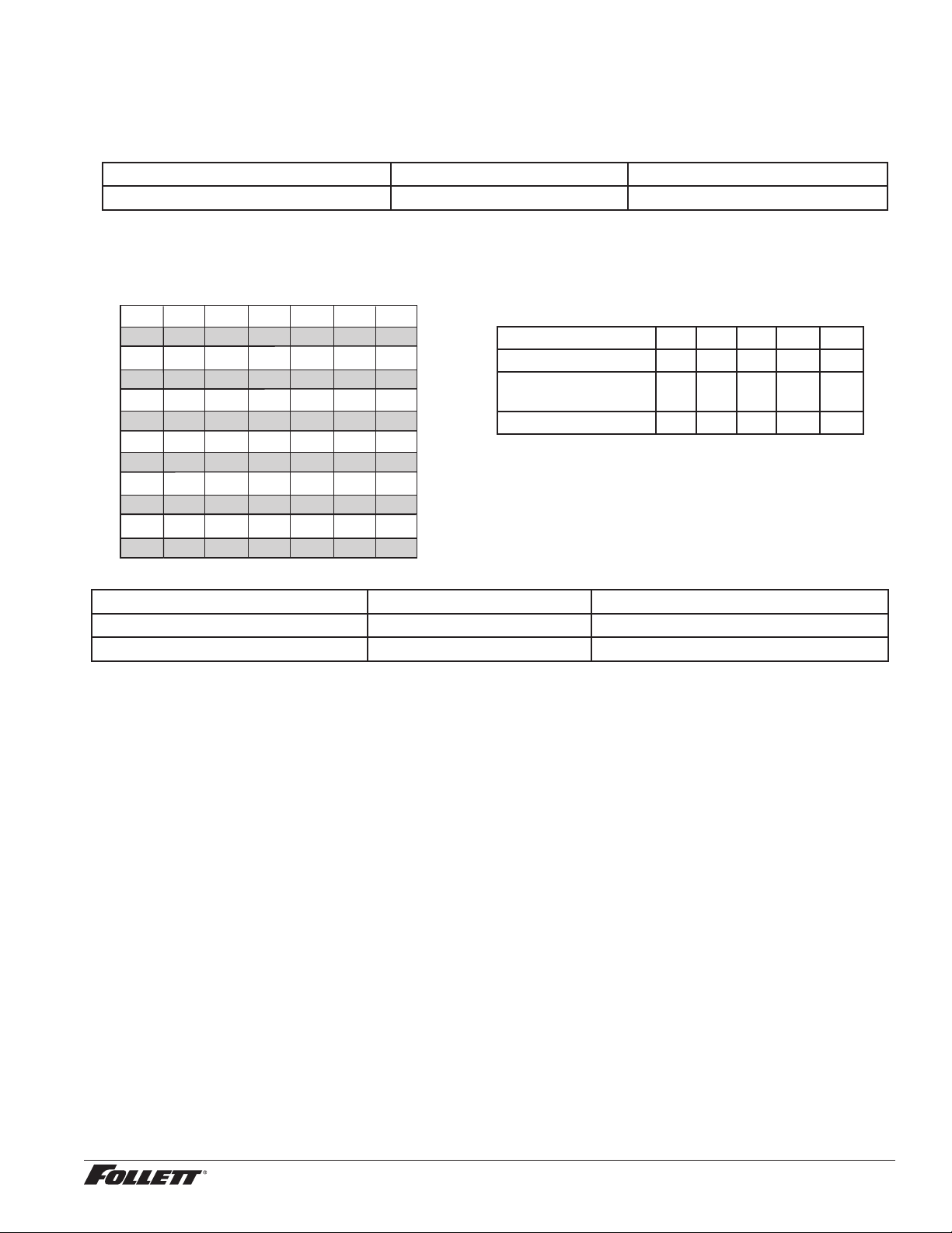
R425 ice machine charge specications
Model Charge Refrigerant type
12CI425A, 12HI425A (air-cooled) 15 oz R404A
Refrigeration pressure data
Ambient Air Temperature ˚F/˚C
Inlet Water Temperature ˚F/˚C
F
C
50
10
60
16
70
21
80
27
90
32
60
16
460
208
437
198
415
188
405
184
395
179
70
21
425
193
405
184
385
175
375
170
365
166
80
27
390
177
372
169
355
161
345
156
335
152
90
32
355
161
340
154
325
147
315
142
305
138
100
38
320
145
307
139
295
134
285
129
275
125
lbs.
kg.
lbs.
kg.
lbs.
kg.
lbs.
kg.
lbs.
kg.
Air-cooled ice machine capacity/24 hrs.
Compressor data
Compressor current draw
Air-cooled
Air temp (F) 60 70 80 90 100
Comp Amperage (A) 5.8 6.1 6.2 6.2 6.3
High-side Pressure
(psi)
190 220 250 290 330
Low-side Pressure (psi) 27 29 31 33 36
Locked rotor amps 48A
Gearmotor Data Split-Phase PSC (permanent split capacitor)
Gearmotor current 1.8A-1.9A (nominal) 0.8A-0.9A (nominal)
Locked rotor amps 14A 7A–14A (temperature dependent)
12CI425A, 12HI425A 5
Installation
Before you begin
§ All dispensers must be installed level in both directions to ensure proper operation.
§ Service and ventilation clearances: 6" (15.3 cm) on right side of dispenser, 6" (15.3 cm) at top for ventilation and
12" (30.5 cm) at top recommended for service.
§ Countertop units installed without legs provide the option of taking utilities out bottom or back of dispenser (on
wall mount units and countertop units with legs, utilities exit from back). See counter cutout drawings for bottom
exiting utilities. For installations where utilities exit through back of dispenser, refer to back view drawings.
§ Wall mount models without drain pan are designed for use above sinks.
§ Counter depth must allow front of sink to be a minimum of 30.00" (76.2 cm) from wall.
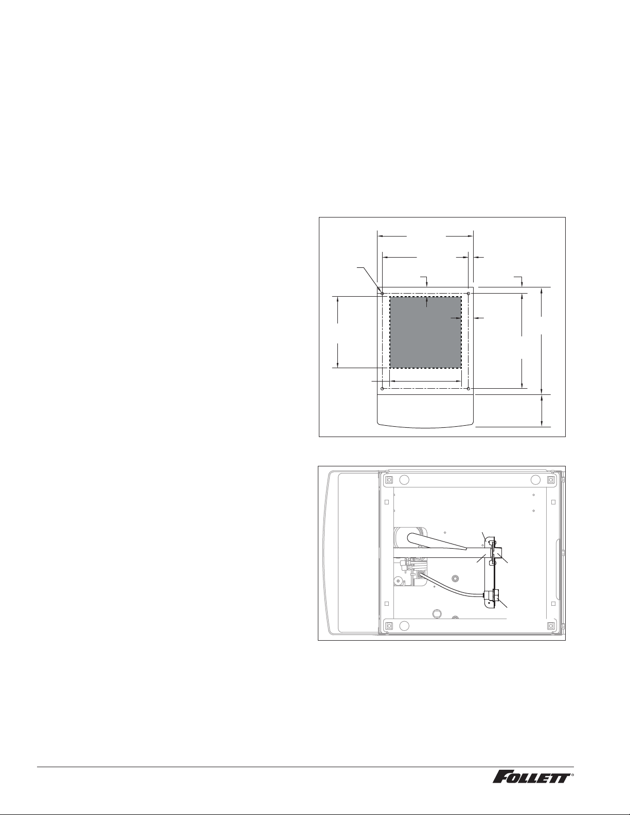
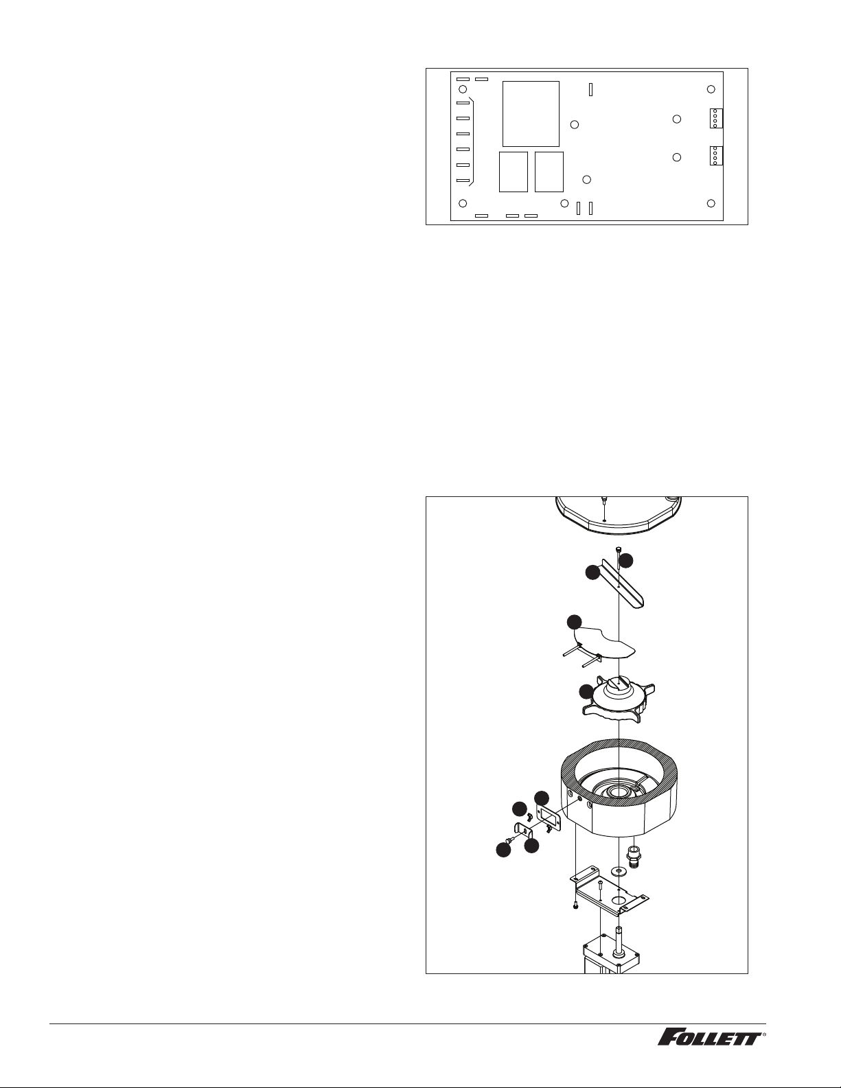
Installing countertop dispensers without
legs
1. Position dispenser in desired location, mark
dispenser outline on counter and remove
dispenser.
2. Regardless of whether utilities will exit
through back or bottom of dispenser,
drill four 7/16" holes in counter to anchor
dispenser to counter (Fig. 1).
3. For utilities exiting through bottom only:
(a) Make cut out (Fig. 1).
(b) Move drain tting from back of dispenser and
mount (Fig.2).
(c) Cut drain tube to length and attach to barbed
connection.
(d) Move inlet water tting from back of
dispenser and mount (Fig.2).
(e) Cut water tubing to length and re-insert into
water tting.
4. For all units: Apply a thick bead
approximately 1/4" (7 mm) diameter of
NSF-listed silicone sealant (Dow Corning
RTV-732
®
or equivalent) 1/4" (7 mm) inside
marked outline of dispenser.
5. Carefully lower dispenser on counter in
proper position and secure to counter with
four (4) 3/8"-16UNC bolts.
6. Smooth excess sealant around outside of
dispenser.
Fig. 1
2.00"
(5.1 cm)
12.00"
(30.5 cm)
14.37"
(36.5 cm)
4X
Ø.437"
(11 mm)
hole
1.04"
(2.6 cm)
16.00"
(40.7 cm)
Cutout
connections
through
bottom
12.00"
(30.5 cm)
0.81"
(2.1 cm)
16.00"
(40.7 cm)
1.50"
(3.8 cm)
17.87"
(45.4 cm)
5.62"
(14.3 cm)
Fig. 2 - Bottom exiting utilities (countertop units)
bracket
inlet
tting
drain
tting
drain tube
6 12CI425A, 12HI425A
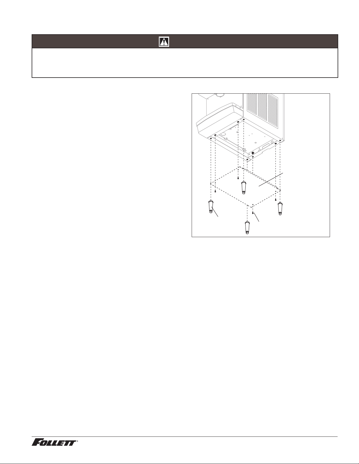
Installing countertop dispensers with legs accessory (P/N AF10LBLEGS)
CAUTION!
§ Do not tilt unit further than 30° off vertical plane.
§ Countertop dispensers that sit on legs (not bolted to counter) can be inadvertently moved. Care should be taken
when operating and cleaning to avoid accidents.
1. Carefully tip dispenser back to expose
underside and block up in place.
2. Screw legs (shipped taped to drain pan of
dispenser) into dispenser bottom, taking
care to seat legs securely against underside
of dispenser.
3. Attach bottom panel and hardware to bottom
of dispenser with supplied screws (Fig. 3).
4. Position unit in desired location and adjust
legs to level in both directions.
5. Make nal connections.
Fig. 3 - Bottom panel and leg assembly
bottom panel
screw
leg
12CI425A, 12HI425A 7
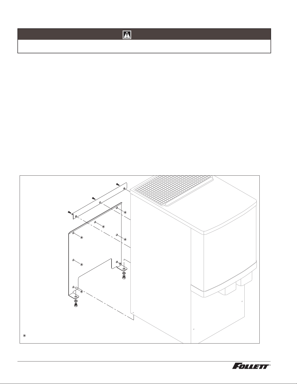
Installing wall mount dispensers
CAUTION!
§ WALL PREPARATION: Wall and fasteners must be of sufficient strength to carry weight of unit (185 lb (83.9kg).
Hardware for this is not included.
Notes:
§ SensorSAFE™ infrared dispensing is standard.
1. Recommended minimum counter depth and mounting height (Fig. 6) ensures that ice will drop into sink.
2. See Fig. 6 for model dimensions. The dimensions include the 0.5" (13 mm) mounting bracket supplied with the
unit.
3. Cut utility hole in wall as shown (Fig. 5).
4. Mount support bracket to wall using fasteners of sufficient strength (fasteners not included, see Fig.4).
5. Rough in water and drain lines (3/4" copper recommended for drain) (Fig. 9).
6. Lift dispenser onto support bracket, positioning unit so that hook on back of dispenser is captured by support
bracket angle (Fig. 6).
7. Install two (2) supplied 3/8"-16UNC screws through bottom of support bracket into bottom of dispenser (Fig. 4).
Slotted holes in support bracket allow you to adjust and level the dispenser. Ensure that the top of dispenser is
level or tilted slightly back toward the wall.
8. Remove bottom cover and make nal connections (Fig. 7).
9. Attach bottom panel and hardware to bottom of dispenser (Fig. 8).
10. Clean dispenser prior to use.
Fig. 4 – Wall mount bracket and fastener requirements
support bracket
screw
wall mounting bracket
= Customer supplied.
8 12CI425A, 12HI425A
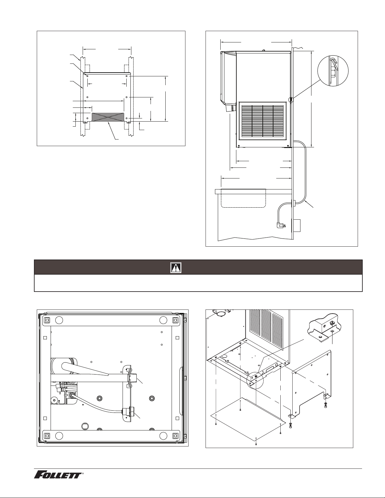
Fig. 5 – Wall mount dimensions
ANCHOR POINTS
0.438" (11 mm)
CLEARANCE
FRONT VIEW
13.00" (33.0 cm)
16.00" TYP.
(40.6 cm)
2.88" (7.3 cm)
2.88" (7.3 cm)
13.50" (34.3 cm)
WALL CUTOUT
WALL STUDS
WALL MOUNT
BRACKET
1.08" (2.7 cm)
8.08" (20.5 cm)
15.08" (38.3 cm)
Fig. 6 – Wall mount side view
20.53" (52.2 cm)
18.51" (47.0 cm)
30.00" (76.2 cm)
MIN DISTANCE TO SINK FRONT
23.70"
(60.2 cm)
SUGGESTED POWER
CORD ROUTING
32.00" (81.3 cm)
CAUTION!
§ Do not rest dispenser weight on bottom of support bracket. Dispenser weight to rest on top of the support bracket
(Fig. 6).
Fig. 7 – Wall mount unit bottom panel assembly
3/8” FNPT
Water
3/4” MNPT
Drain
BOTTOM VIEW
Fig. 8 – Wall mount unit bottom panel assembly
nut
support
bracket
screw
bottom panel
12CI425A, 12HI425A 9
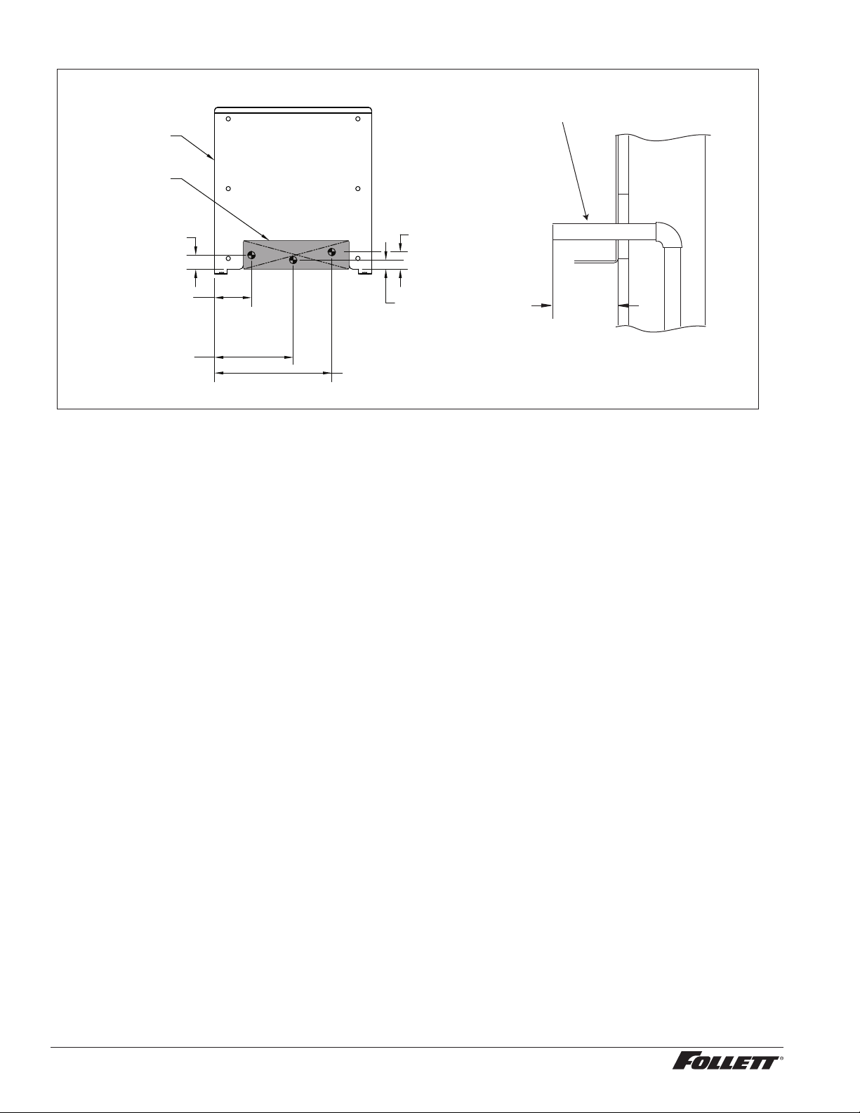
Fig. 9 – Wall mount, utility location
FRONT VIEW
WALL MOUNT
BRACKET
3.70" (9.4 cm)
POTABLE WATER SUPPLY
3/8 COPPER TUBE
7.88" (20.0 cm)
DRAIN
3/4 COPPER TUBE
11.75" (29.9 cm)
POWER CORD EXIT
1.41" (3.6 cm)
0.92" (23 mm)
1.72" (4.4 cm)
WALL
CUTOUT
water and
drain tubing
(7.7 m)
MAX.
3.00"
WALL
SIDE VIEW UTILITIES EXITING WALL
User information
How the dispenser works
Follett’s 12 series automatic-load ice and water dispensers are equipped with Follett’s 425 lb (193 kg)/day ice
machine. In the continuous icemaking process, water freezes to the inside wall of the evaporator. A rotating
stainless steel auger carries the ice to the top of the evaporator where it is compressed and extruded through an
outlet port. The ice is then pushed through a tube to the storage hopper. When the hopper is full, a bin thermostat
opens and shuts the ice machine off. When the dispense mechanism is activated, a dispense motor is turned on,
causing the wheel to turn. This moves ice to the dispense chute where it drops by gravity into the container held
below the chute.
How SensorSAFE infrared dispensing works
Follett’s SensorSAFE infrared dispensing maximizes sanitation and minimizes the possibility of cross-contamination
by eliminating physical contact between the cup or container and dispenser. Sensors in the panel use reected
infrared light to detect the presence of the container and send a signal to a control board which then activates the
appropriate components for ice or water dispensing.
The SensorSAFE infrared dispensing package includes a cleaning switch under the left side of the front cover
which temporarily shuts off dispensing to allow cleaning of the panel and lenses. If the switch is not turned back on
after cleaning, the dispenser automatically resets after two minutes for normal operation.
SensorSAFE infrared dispensing also includes a time limit safety feature which automatically stops ice dispensing
after one minute of continuous dispensing. Dispensing can be resumed by moving the container away from the
dispenser and returning it to the activation zone.
10 12CI425A, 12HI425A
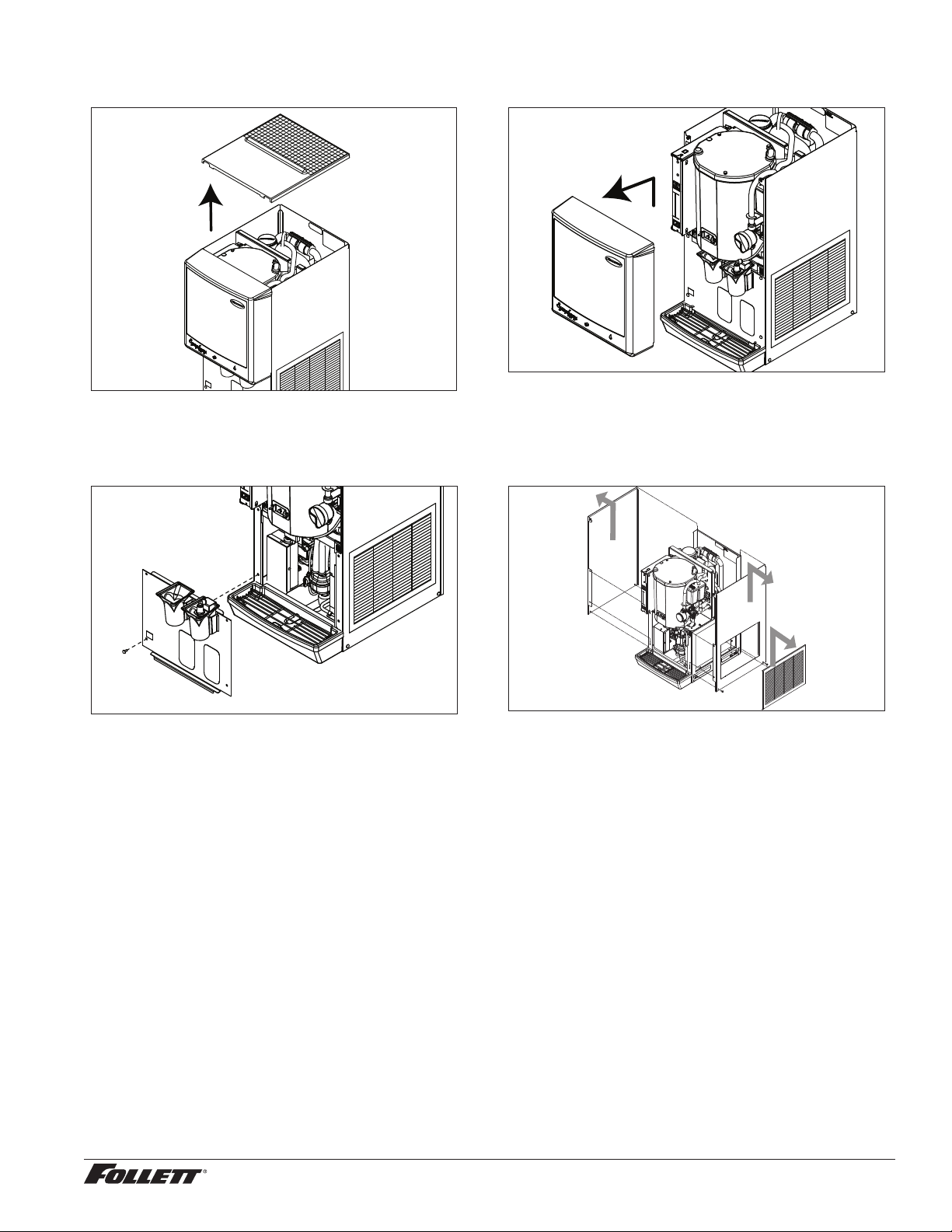
Panel removal
Fig. 10 Fig. 11
Top cover: Lift cover up and off Velcro strips. Front cover: Pull bottom of cover, then lift cover up and
forward to unhook from keyhole slots.
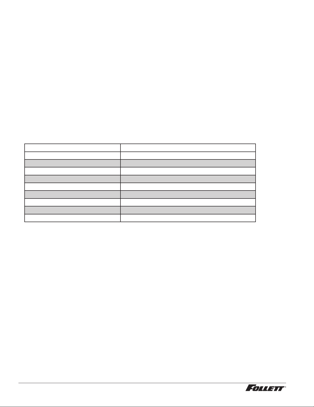
Fig. 12
Fig. 13
Splash panel: Remove 4 screws. Pull out bottom
of panel to allow top to slide out from under hopper
support lip.
Side panels: Remove screws. Lift panel to disengage
from back panel, then remove. Note: Before removing
right hand side, remove side louver panel by lifting up
and pulling forward on panel.
12CI425A, 12HI425A 11
Cleaning and sanitizing
Follett ice machines and dispensers, and their associated cleaning and sanitizing procedures, are designed for
use with potable water sources. The presence, or suspected presence, of infectious agents may call for additional
measures, including the replacement of components and more comprehensive disinfection measures. Follett
recommends that these cleaning and sanitizing procedures be reviewed with the appropriate infectious agent
subject matter experts to assure complete remediation.
Periodic cleaning of Follett’s ice and water dispenser and ice machine system is required to ensure peak
performance and delivery of clean, sanitary ice. The recommended cleaning procedures that follow should be
performed at least as frequently as recommended and more often if environmental conditions dictate.
Follett recommends sanitizing the pressurized water lines prior to cleaning the ice machine/dispenser. Follett
offers two kits: order P/N 01089572 when a Follett lter system with a pre-lter bowl is present, or P/N 01089580
when a Follett lter system is not present. Follow the instructions provided with the respective kits to sanitize the
pressurized water lines immediately before cleaning the ice machine/dispenser.
Cleaning of the condenser can usually be performed by facility personnel. Cleaning of the ice machine system
should be performed by your facility’s trained maintenance staff or a Follett authorized service agent. Regardless
of who performs the cleaning, it is the operator’s responsibility to see that this cleaning is performed according to
the schedule below. Service problems resulting from lack of preventive maintenance will not be covered under the
Follett warranty.
Recommended cleaning intervals*
Symphony Plus Frequency
Drain Line weekly
Drain Pan/Drip Pan weekly
Exterior as needed
Condenser monthly (air-cooled only)
Dispenser and Components semi-annually
Ice Machine semi-annually
Transport Tube semi-annually
Ice Storage Area/Bin semi-annually
Pressurized Water Sanitizing semi-annually
* Ice machine and dispenser must be cleaned prior to start-up.
12 12CI425A, 12HI425A
Weekly
CAUTION!
§ Do not use solvents, abrasive cleaners, metal scrapers or sharp objects to clean any part of the dispenser.
Dispenser drain pan and drain line
§ Pour 1 gal. (3.8 L) of hot tap water into drain pan to ush drains.
Splash panel front, SensorSAFE infrared dispensing
1. Deactivate dispensing by pressing and releasing clean switch located on left side of unit under top front
cover.
2. Clean lens and splash panel front using a soft cloth and mild, non-abrasive, non-chlorine based cleaner.
3. Reactivate dispensing by pressing and releasing clean switch again.
Monthly
CAUTION!
§ Do not use solvents, abrasive cleaners, metal scrapers or sharp objects to clean any part of the dispenser.
Condenser (air-cooled ice machine only)
§ Use a vacuum cleaner or stiff brush to carefully clean condenser coils of lint and debris to ensure optimal
performance.
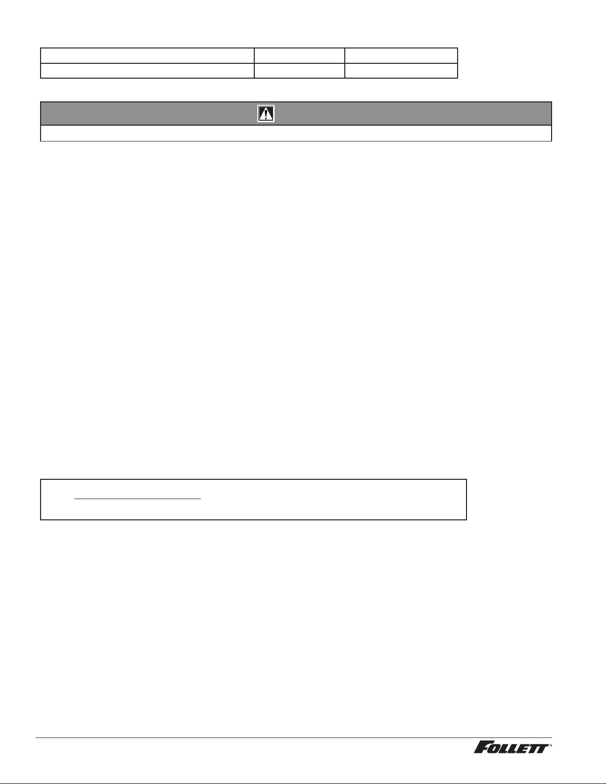
Semi-Annually (more often if conditions dictate)
§ A cleaning procedure should always include both the ice machine and dispenser.
§ Icemaking system can be cleaned in place.
CAUTION!
§ Wear rubber gloves and safety goggles (or face shield) when handling SafeCLEAN Plus and IMS-III solutions.
§ Use only Follett approved cleaners.
§ It is a violation of Federal law to use the Nu-Calgon
®
IMS-III solution in a manner inconsistent with its labeling.
§ Do not use solvents, abrasive cleaners, metal scrapers or sharp objects to clean any part of the dispenser.
Cleaning & sanitizing tool checklist
§ (1 or 2) 1.5 gallon (or larger) plastic bucket
§ (2) clean cloths
§ Sanitary gloves
§ Safety glasses
§ (2) SaniSponge™ (P/N 00131524 - single sponge)
§ SafeCLEAN Plus ice machine cleaner
§ [OPTIONAL] Nu-Calgon IMS-III no-rinse sanitizer (P/N 00979674 – 16 oz. bottle)
SafeCLEAN Plus Solution: Follow the directions on the SafeCLEAN Plus packaging to mix 1 gal. (3.8 L) of
Follett SafeCLEAN Plus solution. Use 100 F (38 C) water.
[OPTIONAL] No-rinse Sanitizing Solution: Follow the directions on the Nu-Calgon IMS-III packaging to mix
1gal. (3.8 L) of sanitizing solution. Use 100 F (38 C) water.
12CI425A, 12HI425A 13

Ice Machine and Dispenser
Cleaning procedure
Note: Check drains and drain cup to ensure they are open and owing freely.
1. If ice machine was running recently, ensure that the evaporator is completely free of ice before
proceeding. If there is ice in the evaporator, complete steps 2-7 using only hot water to remove the ice
then begin Cleaning Procedure again.
2. Remove front cover and turn OFF bin signal switch.
3. Dispense all ice from storage hopper and discard.
4. Remove top of machine and hopper lid.
5. Press CLEAN switch. The MAINTENANCE light will turn on and the machine will drain. Wait for the LOW
WATER light to turn on.
6. Remove lid from cleaning cup and ll (about 1 quart) until SafeCLEAN Plus solution overows from the
ice transport tube into the hopper. Place lid back on cup. Save remainder of SafeCLEAN Plus solution.
7. CLEANER FULL light will turn on and machine will start cleaning cycle then rinse three times; this
process takes approximately 15 minutes.
8. While ice machine is cleaning, clean dispenser as follows:
a. Remove center thumbscrew, locking plate, two wingnuts and backing plate from front of storage hopper.
b. Remove stud assembly, baffle, wheel, and any remaining ice.
c. Remove dispense chutes from splash panel.
d. Remove water dispense tube. Soak in SafeCLEAN Plus solution and clean thoroughly with a small brush.
Rinse with clean water and reinstall.
e. Submerse drain grille in SafeCLEAN Plus solution and allow to soak to remove any scale buildup.
f. Wipe inside of hopper lid, stud assembly, baffle, wheel, inside of storage area, dispense chutes, drain grille
and drain pan with damp cloth wrung out in SafeCLEAN Plus solution. Thoroughly rinse all parts with damp
cloth wrung out with clean water.
Note: To avoid possible damage to motor assembly, only use a damp cloth to clean storage hopper. Do not
allow water to run through motor shaft hole in bottom of hopper.
9. When machine is nished cleaning, the MAINTENANCE light will turn off.
Finish cleaning – SafeCLEAN Plus only
10. Reinstall dispense chutes, wheel, baffle, stud assembly and knurled nuts.
11. Remove top bearing insulation. Loosen Phillips-head screw on nozzle connected to evaporator. Remove
nozzle from evaporator side only, leave other side of nozzle connected to transport tube.
12. Soak one SaniSponge in remaining SafeCLEAN Plus solution.
13. Insert the sponge soaked in SafeCLEAN Plus solution into nozzle then insert a dry sponge into the
nozzle.
14. Replace nozzle onto evaporator and tighten screw. Ensure drain is connected to reservoir and vent tubes
are connected to evaporator drain pan. Replace top bearing insulation.
15. Turn ON bin signal switch. Wait for ice to push sponges through transport tube.
16. Collect sponges from ice storage bin.
1 7. Replace hopper lid, machine top, and install front cover.
18. After 10 minutes, dispense all ice and discard.
14 12CI425A, 12HI425A

[OPTIONAL] Finish cleaning – No-rinse sanitizing with Nu-Calgon IMS-III
19. Press CLEAN switch. The MAINTENANCE light will turn on and the machine will drain. Wait for the LOW
WATER light to turn on.
20. Remove lid from cleaning cup and ll (about 1 quart) until sanitizing solution overows from the ice
transport tube into the hopper. Place lid back on cup. Save remainder of sanitizing solution.
2 1. CLEANER FULL light will turn on and machine will start sanitizing cycle then rinse three times; this
process takes approximately 15 minutes.
22. While ice machine is sanitizing, sanitize dispenser as follows:
a. Wipe inside of hopper lid, stud assembly, baffle, wheel, inside of storage area, dispense chutes, drain grille
and drain pan with damp cloth wrung out in sanitizing solution. Do not rinse off the sanitizing solution.
Note: To avoid possible damage to motor assembly, only use a damp cloth to clean storage hopper. Do not
allow water to run through motor shaft hole in bottom of hopper.
23. Reinstall dispense chutes, wheel, baffle, stud assembly and knurled nuts.
24. When machine is nished rinsing, the MAINTENANCE light will turn off.
25. Remove top bearing insulation. Loosen Phillips-head screw on nozzle connected to evaporator. Remove
nozzle from evaporator side only, leave other side of nozzle connected to transport tube.
26. Soak one SaniSponge in remaining sanitizing solution.
2 7. Insert the sponge soaked in sanitizing solution into nozzle then insert a dry sponge into the nozzle.
28. Replace nozzle onto evaporator and tighten screw. Ensure drain is connected to reservoir and vent tubes
are connected to evaporator drain pan. Replace top bearing insulation.
29. Turn ON bin signal switch. Wait for ice to push sponges through transport tube.
30. Collect sponges from ice storage bin.
3 1. Replace hopper lid, machine top, and install front cover.
32. After 10 minutes, dispense all ice and discard.
User Interface and Exterior Cabinet
§ Clean stainless steel panels with stainless steel cleaner.
12CI425A, 12HI425A 15
Service
Ice machine operation (all models)
Follett’s ice machine consists of four distinct functional systems:
§ Harvesting system
§ Water system
§ Electrical control system
§ Refrigeration system
These four systems work together to accomplish the production and harvesting of ice. A problem in any one of
these systems will result in improper operation of the entire ice production cycle. When troubleshooting the ice
machine, it is important to analyze the entire system operation to determine which system is not functioning
properly, then pinpoint the component within that system that is malfunctioning. Determine what corrective action
must be taken before making any adjustments or replacing any components.
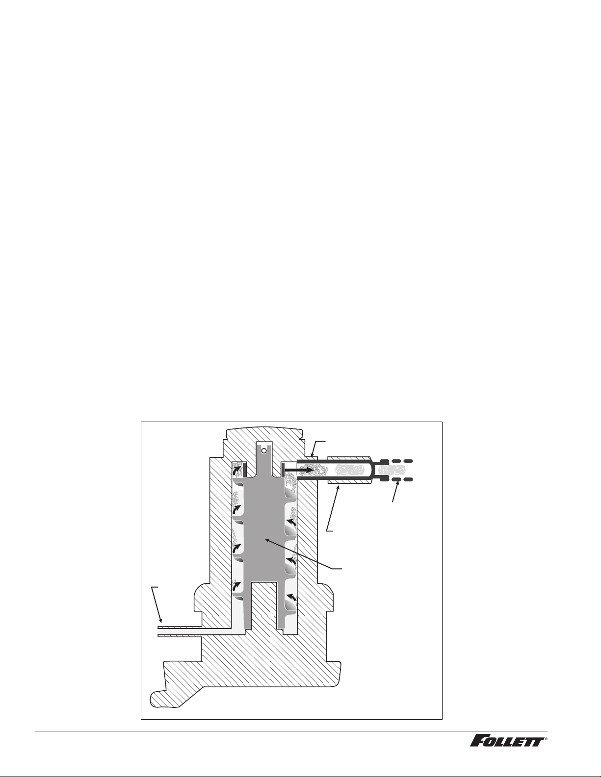
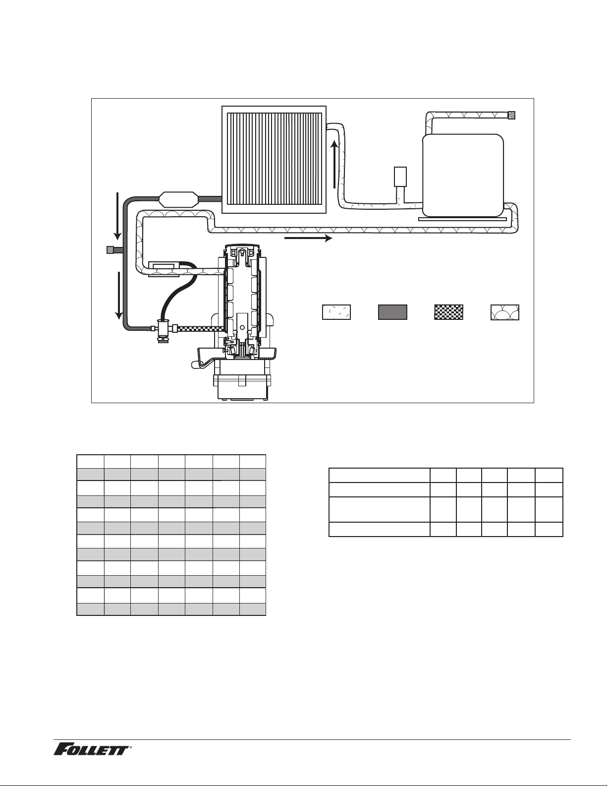
The icemaking process
The Maestro Plus ice machine uses a stainless steel jacketed evaporator and operates on a continuous
freezing cycle. Water is supplied to the evaporator from the water reservoir where the water level is controlled by
conductivity probes.
When the ice machine is running, a layer of ice forms on the interior surface of the evaporator. This ice is
continuously removed by a slowly rotating (12RPM) auger. The auger carries the ice upward into the cavity
formed by the top bearing housing and the compression loop, where it is compressed to remove excess water.
When the ice reaches the desired hardness it rotates within the cavity and is forced through a discharge port
and compression nozzle and into the ice transport tube. The discharge tube and compression nozzle are slightly
restricted to further compress the ice and produce the desired hardness.
A solid state control board located in the electrical box of the ice machine controls the normal operation of the ice
machine and monitors gearmotor torque. This control board will shut down the ice machine should an over-torque
condition occur. It is very important that you familiarize yourself with the operational sequences detailed in this
manual before attempting to service the ice machine.
WATER
INLET
AUGER
COMPRESSION NOZZLE
ICE TRANSPORT TUBE
EVAPORATOR
PORT
16 12CI425A, 12HI425A
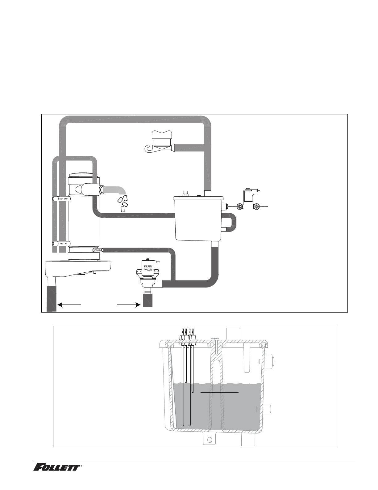
Water system
The water level in the evaporator is controlled by a ll solenoid (Fig. 14) and level detecting sensors. Water sensing
rods (Fig. 15) extend down into the reservoir at the end of the evaporator assembly. The system works via electrical
conductivity as follows:
One of the longest probes is a common. When water is between any of the other probes and the common, the
PC board will sense the activation. During normal operation, the water level rises and falls between the Normal
High and Normal Low sensors. As water is consumed to make ice, the level will fall until the Normal Low sensor is
exposed, triggering the water feed solenoid on. Water will ll until the Normal High sensor is activated.
Note: The potable water dissolved solids content must be greater than 10 ppm for the water control system to
function properly. If using reverse osmosis water ltration system, ensure T.D.S level is greater than 10 ppm.
Fig. 14 – Water system diagram
CLEANING CUP
WATER SUPPLY
3/8" FPT, 45-90 F (7-32 C)
10-70 PSI (69-483 KPA)
RESERVOIR FILL
SOLENOID
WATER
RESERVOIR
EVAPORATOR
ICE
NOZZLE
DRAIN PAN
VENT
TO DRAIN CUP
Fig. 15 – Water level diagram
B A
C
D
B: COMMON (BLACK)
C: HIGH (ORANGE)
A: ALARM LOW (RED)
D: LOW (YELLOW)
NORMAL OPERATING RANGE
12CI425A, 12HI425A 17
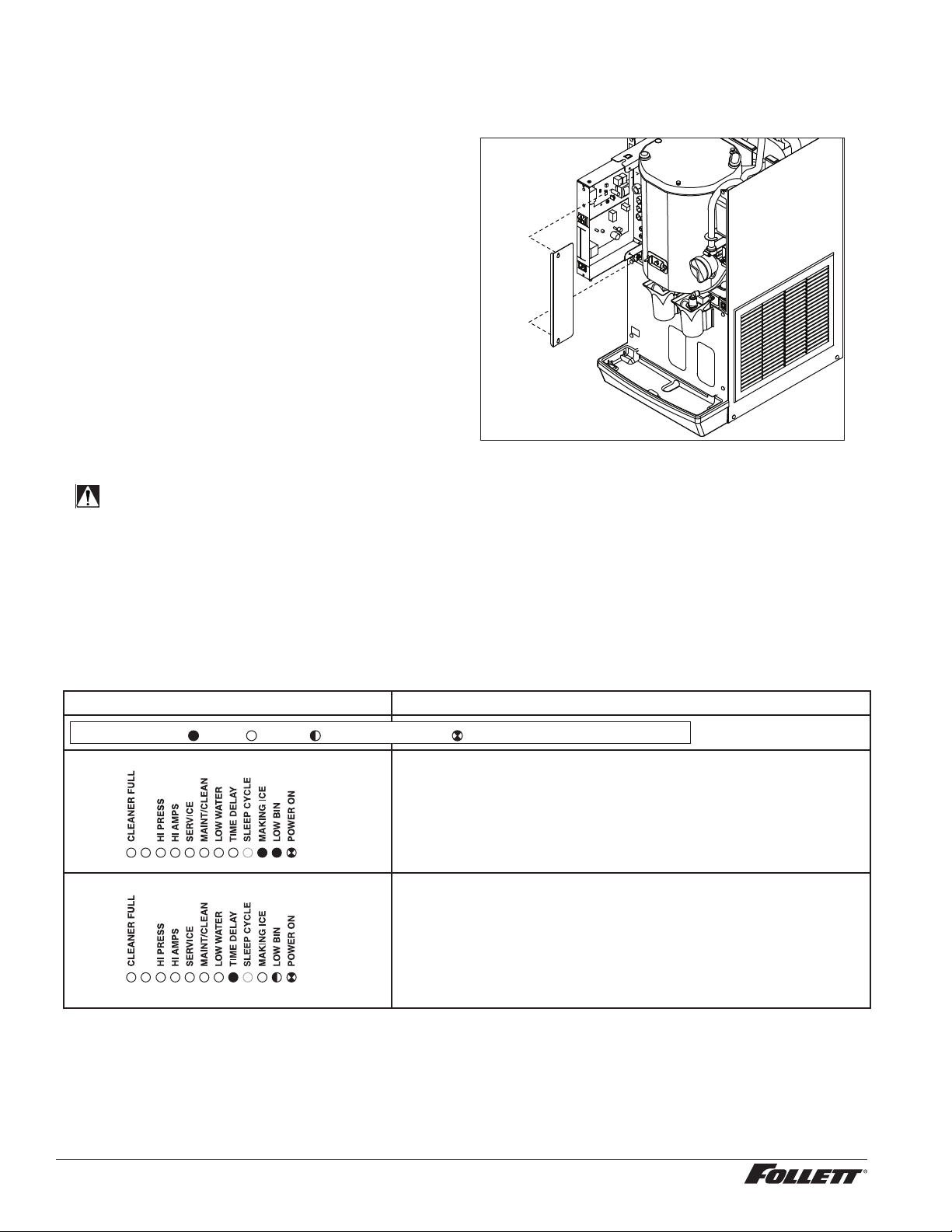
Access to electrical box and control board
The 12 series electrical box has been designed to slide out for easy access to the control board and more
convenient troubleshooting.
1. Remove top and front panels of dispenser
(for panel removal instructions see page12).
2. Remove electrical box cover.
3. Pull electrical box toward front of unit.
Fig. 16
electrical box
electrical
cover
Electrical system
ATTENTION!
To prevent circuit breaker overload, wait 15 minutes before restarting this unit. This allows the
compressor to equalize and the evaporator to thaw.
Normal control board operation
The PC board indicator lights provide all the information necessary to determine the machine's status. Green
indicator lights generally represent “go” or normal operation; Yellow indicators represent normal off conditions; Red
indicators generally represent alarm conditions, some of which will lock the machine off.
A ashing green light labeled POWER indicates power to the machine. All other normal operation status indicators
are covered as follows:
Ice machine disposition Operating conditions
FLASHINGON or OFF
Legend:
OFFON
1. Ice machine is making ice. 1. Normal running.
2. Ice machine is not making ice.
2. Normal time delay. When the bin lls with ice, the LOW BIN
light goes out momentarily and the refrigeration and auger
drive systems immediately shut down. (Note: The fan motor
will continue to run for 10 minutes to cool condenser) The TIME
DELAY light comes on, initiating the time delay period. When
the time delay expires, the machine will restart provided that the
LOW BIN light is on.
18 12CI425A, 12HI425A
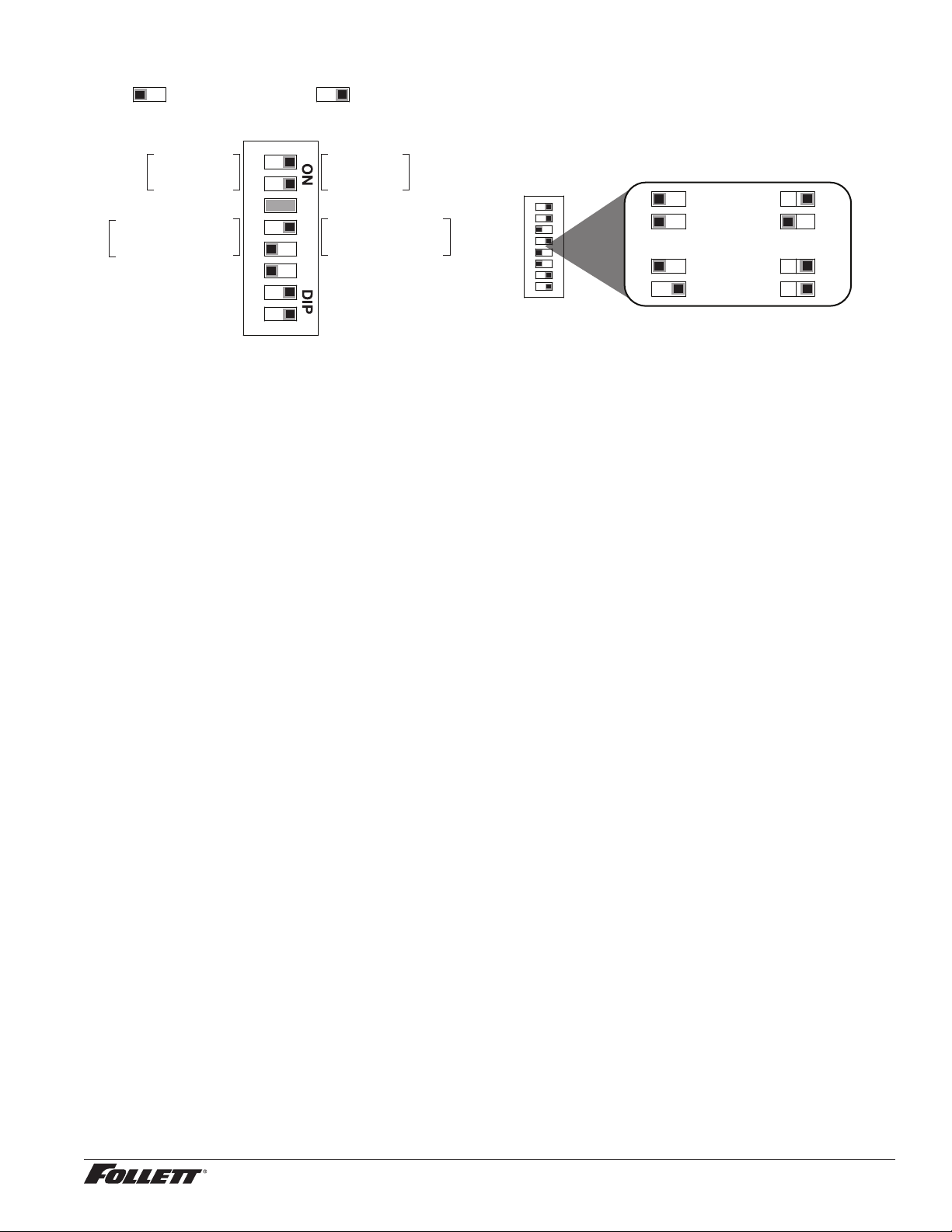
Control board DIP switch settings
Sleep cycle dispense duration
OFF ON
1 2 3 4 5 6 7 8
4 5 4 5
4 5 4 5
35 s
15 s
5 s
60 s
OFF POSITION ON POSITION
Sleep cycle
enabled
Not used
Sleep cycle
dispense duration
60 min. time delay
Flush enabled
Maint. timer OFF
OFF ON
Sleep cycle
disabled
Not used
Sleep cycle
dispense duration
20 min. time delay
Flush disabled
Maint. timer ON
1 2 3 4 5 6 7 8
Relay/triac output indication
Each relay on the board has an indicator light associated with its output. For example, when the relay for the water
feed solenoid is energized, the adjacent indicator light glows green.
Flushing logic
Off cycle: At the completion of off-cycle time delay, the machine checks for a cumulative one (1) hour of ice making
time since the last off-cycle ush. If the cumulative ice making time exceeds one (1) hour, the machine will open
the drain valve for 60 seconds to drain the evaporator in its entirety. It will then rell with water, ush again and
rell, and begin making ice. If the ice making time is less than 1 hour, the machine will start and begin making ice
without draining the evaporator.
Error faults
The Maestro Plus PC board monitors various operating parameters including high pressure, auger gearmotor
amperage limits, clogged drain, and low water alarm conditions. There are two types of errors namely “hard” or
“soft”. A hard error is one that shuts the machine off and will not allow restart until the reset button is pressed. Even
cycling power will not reset a hard error. A soft error can either be automatically reset should the condition rectify,
or if power is cycled. Should an error occur, consult the troubleshooting guide in this manual or a Follett service
technician.
Soft errors:
Note: For all soft errors, the ice machine will remain off for 1 hour.
LO WATER: During operation, the water level cycles between the normal low and normal high sensors. Should the
water be shut off to a running machine, a soft error will occur. The error sequence is as follows: During operation,
the water level falls to the normal low sensor, and when it does the water feed solenoid is energized. If water is not
detected at the normal low sensor within 10 seconds, a soft error will occur. The machine will shut down and TIME
DELAY and LOW WATER LEDs will be lit. After time delay, the solenoid will energize and remain energized until the
water level is sufficient for restart.
HI PRESSURE: Should the refrigeration pressure rise above 425 psi, the machine will shut down and the TIME
DELAY and HIGH PRESSURE will be illuminated. After the time delay, and if the pressure has fallen back below
the reset point of 295 psi, the machine will restart and the TIME DELAY and HIGH PRESSURE will clear.
HI AMPS: The PC board monitors the amperage of the auger motor. Should the gear motor experience current
draw above the allowable 3A limit or no current draw (0A), the machine will shut down and the TIME DELAY and HI
AMP will be illuminated. After the time delay the machine will restart and the TIME DELAY and HI AMP will clear.
Hard error:
HI AMPS: If a second hi-amp error occurs within 1 hour of the initial hi-amp error, the ice machine will shut off and
the reset on the board must be pressed to clear the error. If a second hi-amp has occurred, the HI AMP LED only
will be illuminated.
DRAIN CLOG: The drain clog sensor, located in the evaporator drain pan will detect the presence of water just
below the top edge of the pan. If water does not properly ow out of the internal or external drain lines it will backup
into the drain pan (especially during a self-ushing purge cycle). Pressing the reset button will restart the ice
machine.
12CI425A, 12HI425A 19
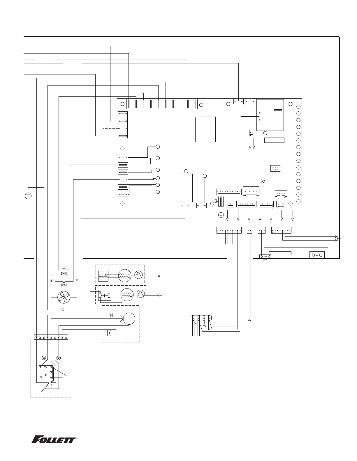
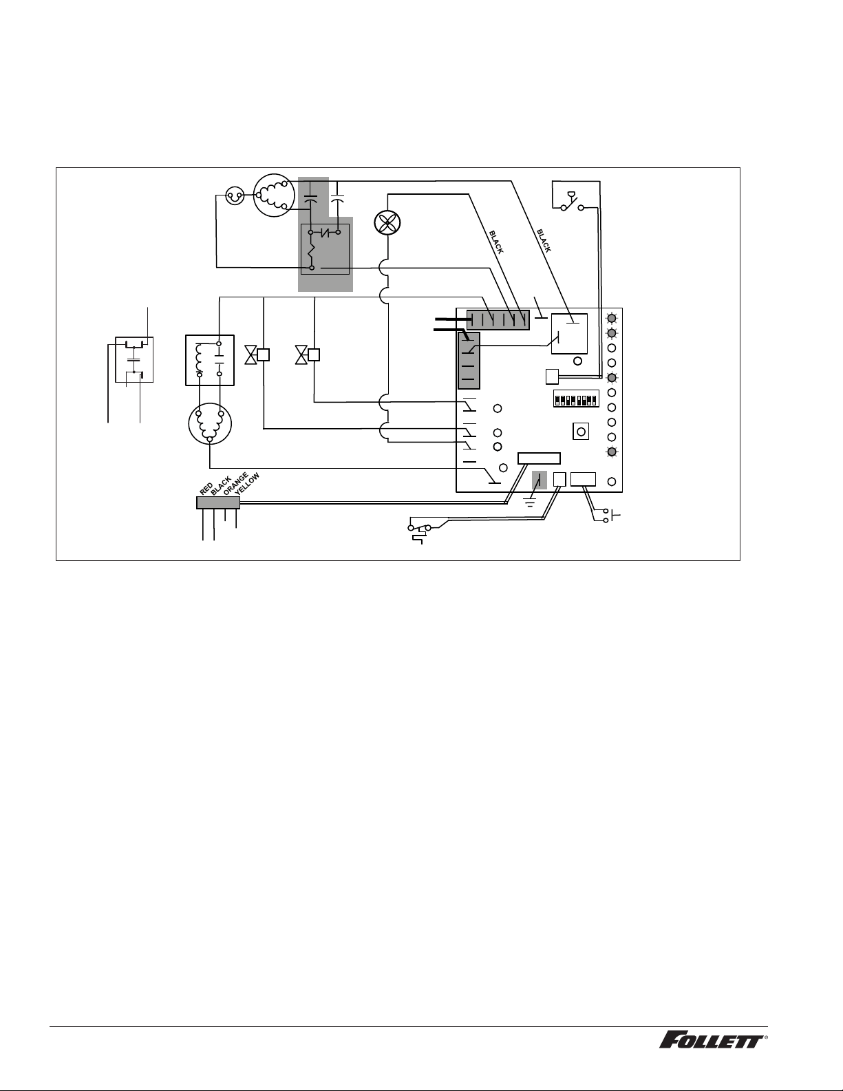
Wiring diagram
WATER LEVELS
P17
BINP12 CLEAN SAFEP11
POWER
LOW BIN
MAKING ICE
SLEEP CYCLE
TIME DELAY
LOW WATER
MAINTENANCE
SERVICE
HI AMPS
HI PRESSURE
CLEANER FULL
RESERVOIR
WATER SENSOR
MAINT.
CLEAN
HI PRS
P14
HIGH
PRESS
P
L1
GND
L2/N
BIN LEVEL
T-STAT
A B C D
BLACK
YELLOW
ORANGE
RED
BIN SIGNAL
SWITCH
MOUNTED ON
SPLASH PANEL
SOL
WTR
NEUTRAL
COMPONENTS
SENSOR
WATER
SENSOR
ICE
CLN
WM
PWR
WTR
L1
GND
ICE
WHITE
BLUE
BISON GEARMOTOR
START
RELAY
3
4
2
YELLOW
BLACK
T.O.L.
START
RUN
FAN
FEED VALVE
DRAIN VALVE
RED #16
BROWN #14
BLACK #36
BLUE #07
GRN #17
GRN #27
BLACK #51
BLACK #23
BLACK #18
BLACK #21
WHITE #22
BLACK #25
GRN #20
BLACK #23
WHITE #26
BLACK #25
BLACK #24
BLACK #38
BLACK #39
GND TO
MAIN FRAME
POWER SWITCH
BLACK #51
WHITE #52
COMP.
R
C
S
O.L.
C2 START
1 2 3 4 5 6 7 8 9
GREEN #53
COMPRESSOR
COMPRESSOR
ELECTRICAL
BOX
BLACK #51
WHITE #52
GREEN #53
RED #54
ORANGE #55
BLACK #56
GREEN #57
BLACK #58
BLACK #59
LEVER ONLY
SENSORSAFE ONLY
BLACK #24
BLACK #25
BLACK #24
BLACK #21 (SENSORSAFE)
BLACK #25 (LEVER)
CLEAN SWITCH
4
1
6
4
1
2
5
BLACK #61
WHITE #62
GREEN #63
WHITE #64
BLACK #65
BLACK #66
GREEN #67
BLACK #68
BLACK #69
C1 RUN
WHEELMOTOR
M
COMPONENTS
MOUNTED ON
MAIN FRAME
4
1
BLACK #33BLACK #41
S
BLACK #32
WHITE #34
WATER
DISPENSE
SOLENOID
BLACK #28
BLACK #31
4
1
BLACK #29
4
1
BLACK #30
LEVER ONLY
WHITE #05
WHITE #35
WHITE #13
WHITE #15
SENSORSAFE ONLY
BLACK #66
BLACK #69
BLACK #71
MODEL SELECT
SERIAL COMM
COMPRESSOR
AUGER
WATER LEVELS
HI PRS
BIN RS485
RS485 UI
CURRENT SENS
RESET
PROGRAM
P5
ICE AUX WATER AUX
D9
D8
D7
D6
D5
D4
D37
D3
D2
D18
D16
D15
D14
D13
D12
D11
D10
D1
T1
P18
P11
P13
P17
P12
P14
P16
P15
P4
T2
S1
S2
K1
P7
P8
P10
K3
1
2
6
5
P9
L1 L1L1
N N N N N N N N N
P2
P1
P21
P20
P19
P3
BLACK #01
P6
P22
D19D22D21D20
D17
D48
WATER STATION
SWITCH
ICE STATION
SWITCH
COVER
INTERLOCK
SWITCH
BLACK #19
BLACK #19
BLACK #23
WHITE #22
WHITE #26
BLACK #23
WHITE #22
WHITE #26
BLACK #24
BLACK #24
BLACK
BLACK
20 12CI425A, 12HI425A
WATER LEVELS
P17
BINP12 CLEAN SAFEP11
POWER
LOW BIN
MAKING ICE
SLEEP CYCLE
TIME DELAY
LOW WATER
MAINTENANCE
SERVICE
HI AMPS
HI PRESSURE
CLEANER FULL
RESERVOIR
WATER SENSOR
MAINT.
CLEAN
HI PRS
P14
HIGH
PRESS
P
L1
GND
L2/N
BIN LEVEL
T-STAT
A B C D
BLACK
YELLOW
ORANGE
RED
BIN SIGNAL
SWITCH
MOUNTED ON
SPLASH PANEL
SOL
WTR
NEUTRAL
COMPONENTS
SENSOR
WATER
SENSOR
ICE
CLN
WM
PWR
WTR
L1
GND
ICE
WHITE
BLUE
SPLIT-PHASE
START
RELAY
3
4
2
YELLOW
BLACK
T.O.L.
START
RUN
FAN
FEED VALVE
DRAIN VALVE
RED #16
BROWN #14
BLACK #36
BLUE #07
GRN #17
GRN #27
BLACK #51
BLACK #23
BLACK #18
BLACK #21
WHITE #22
BLACK #25
GRN #20
BLACK #23
WHITE #26
BLACK #25
BLACK #24
BLACK #38
BLACK #39
GND TO
MAIN FRAME
POWER SWITCH
BLACK #51
WHITE #52
COMP.
R
C
S
O.L.
C2 START
1 2 3 4 5 6 7 8 9
GREEN #53
COMPRESSOR
COMPRESSOR
ELECTRICAL
BOX
BLACK #51
WHITE #52
GREEN #53
RED #54
ORANGE #55
BLACK #56
GREEN #57
BLACK #58
BLACK #59
LEVER ONLY
SENSORSAFE ONLY
BLACK #24
BLACK #25
BLACK #24
BLACK #21 (SENSORSAFE)
BLACK #25 (LEVER)
CLEAN SWITCH
4
1
6
4
1
2
5
BLACK #61
WHITE #62
GREEN #63
WHITE #64
BLACK #65
BLACK #66
GREEN #67
BLACK #68
BLACK #69
C1 RUN
WHEELMOTOR
M
COMPONENTS
MOUNTED ON
MAIN FRAME
4
1
BLACK #33BLACK #41
S
BLACK #32
WHITE #34
WATER
DISPENSE
SOLENOID
BLACK #28
BLACK #31
4
1
BLACK #29
4
1
BLACK #30
LEVER ONLY
WHITE #05
WHITE #35
WHITE #13
WHITE #15
SENSORSAFE ONLY
BLACK #66
BLACK #69
BLACK #71
MODEL SELECT
SERIAL COMM
COMPRESSOR
AUGER
WATER LEVELS
HI PRS
BIN RS485
RS485 UI
CURRENT SENS
RESET
PROGRAM
P5
ICE AUX WATER AUX
D9
D8
D7
D6
D5
D4
D37
D3
D2
D18
D16
D15
D14
D13
D12
D11
D10
D1
T1
P18
P11
P13
P17
P12
P14
P16
P15
P4
T2
S1
S2
K1
P7
P8
P10
K3
1
2
6
5
P9
L1 L1L1
N N N N N N N N N
P2
P1
P21
P20
P19
P3
BLACK #01
P6
P22
D19D22D21D20
D17
D48
WATER STATION
SWITCH
ICE STATION
SWITCH
COVER
INTERLOCK
SWITCH
BLACK #19
BLACK #19
BLACK #23
WHITE #22
WHITE #26
BLACK #23
WHITE #22
WHITE #26
BLACK #24
BLACK #24
BLACK
BLACK
OR
BLUE
CAPACITOR
T.O.L.
START
RUN
BLACK
YELLOW
PSC MOTOR
12CI425A, 12HI425A 21
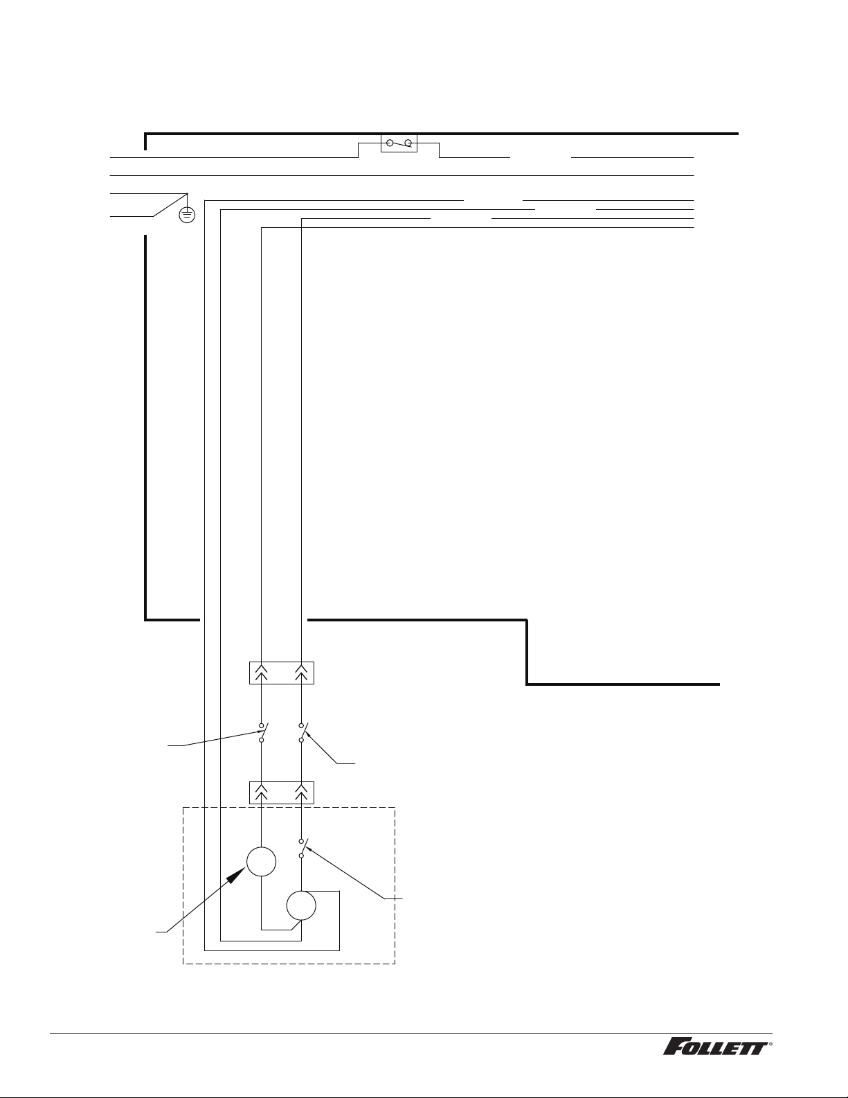
Wiring diagram - Lever only
L1
GND
L2/N
MOUNTED ON
SPLASH PANEL
COMPONENTS
GRN #27
BLACK #25
BLACK #23
WHITE #26
BLACK #25
BLACK #24
GND TO
MAIN FRAME
POWER SWITCH
WHEELMOTOR
M
COMPONENTS
MOUNTED ON
MAIN FRAME
4
1
BLACK #33
BLACK #41
S
BLACK #32
WHITE #34
WATER
DISPENSE
SOLENOID
BLACK #28
BLACK #31
4
1
BLACK #29
4
1
BLACK #30
LEVER ONLY
WATER STATION
SWITCH
ICE STATION
SWITCH
COVER
INTERLOCK
SWITCH
BLACK #19
BLACK #23
WHITE #26
BLACK #24
22 12CI425A, 12HI425A
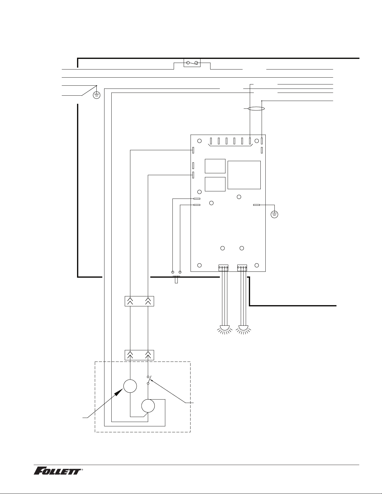
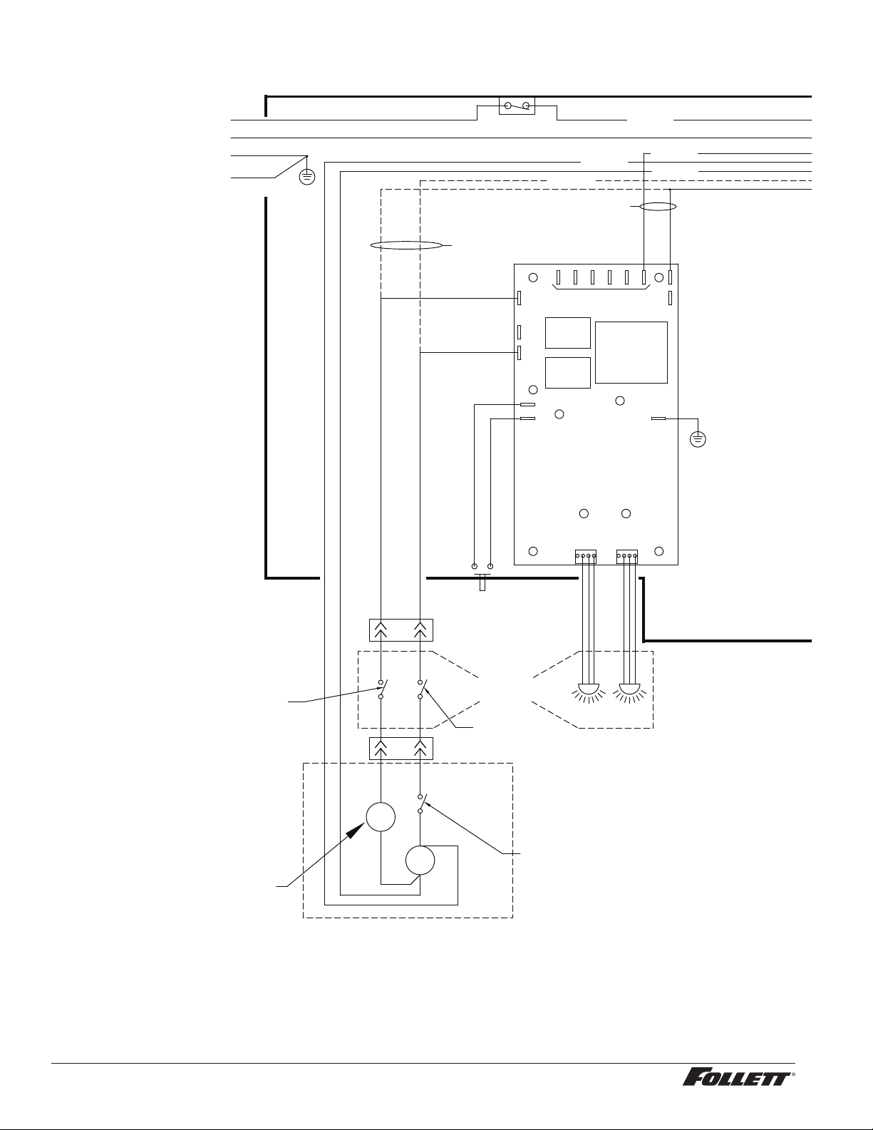
Wiring diagram - SensorSAFE only
SOL
WTR
NEUTRAL
SENSOR
WATER
SENSOR
ICE
CLN
WM
PWR
WTR
L1
GND
ICE
BLACK #21
WHITE #22
GRN #20
BLACK #38
BLACK #39
POWER SWITCH
SENSORSAFE ONLY
BLACK #24
BLACK #25
CLEAN SWITCH
4
1
WHEELMOTOR
M
4
1
S
SENSORSAFE ONLY
BLACK #19
BLACK #23
WHITE #22
WHITE #26
L1
GND
L2/N
MOUNTED ON
SPLASH PANEL
COMPONENTS
GRN #27
BLACK #23
WHITE #26
BLACK #25
BLACK #24
GND TO
MAIN FRAME
COMPONENTS
MOUNTED ON
MAIN FRAME
BLACK #33
BLACK #41
BLACK #32
WHITE #34
WATER
DISPENSE
SOLENOID
COVER
INTERLOCK
SWITCH
12CI425A, 12HI425A 23
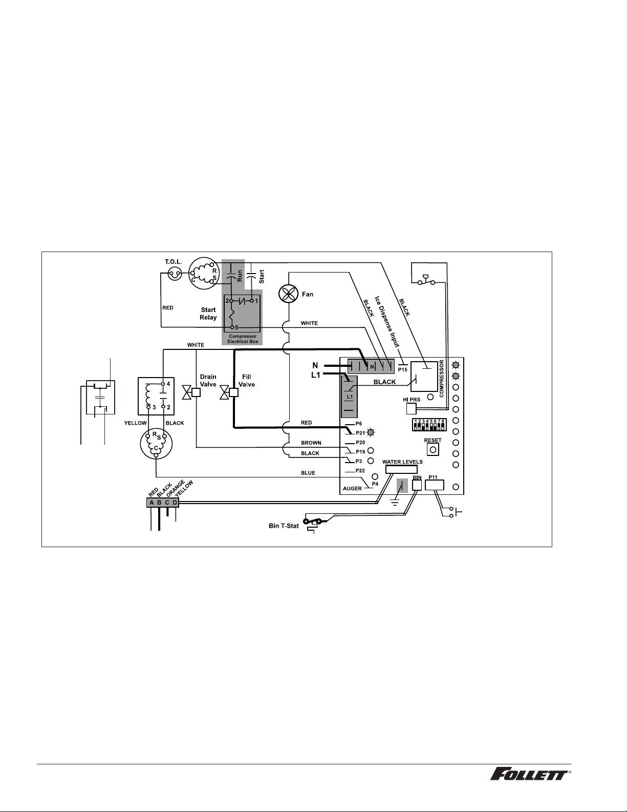
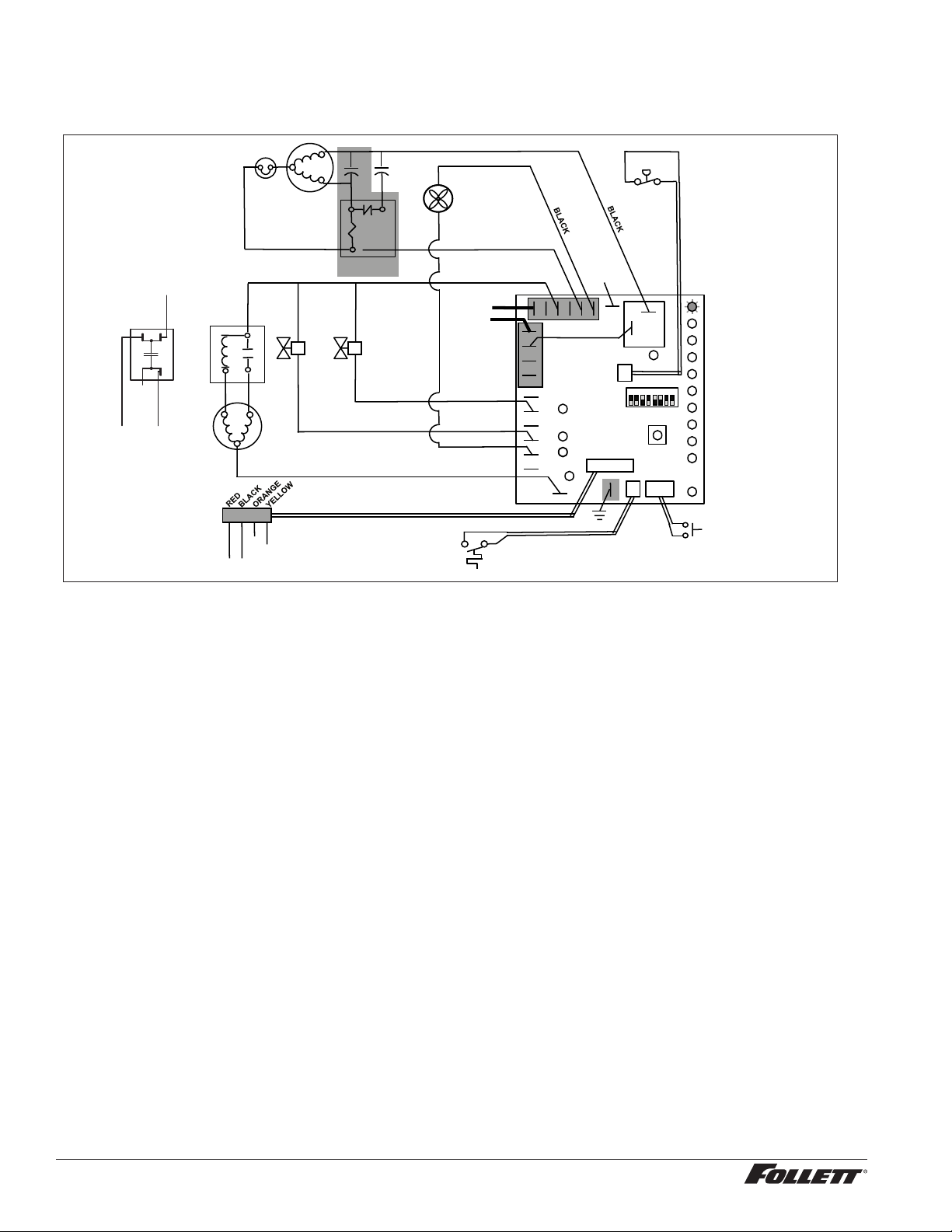
Ice machine operational and diagnostic sequences
The wiring diagrams that follow illustrate the circuitry of Follett ice machines used with 12 series ice dispensers.
Both normal operation (stages 1–8) and non-normal diagnostic sequences showing torque-out for use in
troubleshooting are shown.
Circuitry notes
§ Bin signal is contact closure only - DO NOT SUPPLY POWER.
Note: The operation stage descriptions that follow are based on the unit containing the split-phase gear
motor.
Normal operation – Stage 1
Power is supplied to L1 of the control board, the POWER LED light begins ashing. The ice level bin thermostat in
the dispenser is closed and calling for ice, supplying contact closure to the control board. The LOW BIN LED will
be on. The control board will now go through the start-up sequence. The board checks the water sensors (located
in the reservoir) for continuity between the common probe (B) and the high probe (C). If continuity is not sensed,
the water ll valve (P21) is energized.
Compressor
MAINTENANCE
LOW WATER
TIME DELAY
SLEEP CYCLE
MAKING ICE
LOW BIN
POWER
SERVICE
HI AMPS
HI PRESSURE
CLEANER FULL
Gearmotor
Water Sensors
Clean Switch
High
Pressure
Switch
Start
Relay
OR
Capacitor
BLACK
YELLOW
NO CONNECT
24 12CI425A, 12HI425A
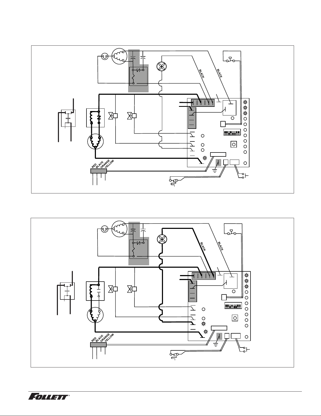
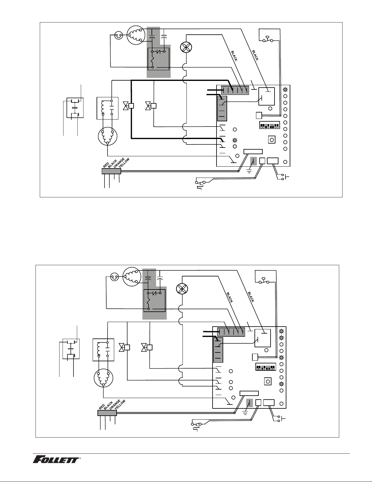
Normal operation – Stage 2
When continuity is seen between B and C, the water valve de-energizes, the AUGER output (P4) comes on along
with the MAKING ICE LED. The auger gearmotor’s start windings are energized through a current style start relay
that is pulled in by the initial high current draw of the gearmotor.
5
2
1
Start
Run
Compressor
T.O.L.
MAINTENANCE
LOW WATER
TIME DELAY
SLEEP CYCLE
MAKING ICE
LOW BIN
POWER
SERVICE
HI AMPS
HI PRESSURE
CLEANER FULL
High
Pressure
Switch
R
S
C
Gearmotor
Start
Relay
Start
Relay
N
L1
Fan
A B C D
Water Sensors
RESET
Fill
Valve
Drain
Valve
3
4
2
Bin T-Stat
Clean Switch
P6
P21
P20
P19
P3
P22
P4
AUGER
WATER LEVELS
BIN
P11
HI PRS
L1
R
S
C
RED
WHITE
WHITE
BLACK
BROWN
BLUE
RED
BLACK YELLOW
Compressor
Electrical Box
COMPRESSOR
1 2 3 4 5 6 7 8
BLACK
N
P15
Ice Dispense Input
OR
Capacitor
BLACK
YELLOW
NO CONNECT
PSC: Start winding
energized through
capacitor.
Normal operation – Stage 3
After the initial high current draw drops off, the gearmotor start relay contacts open, dropping out the start winding.
The condenser fan output (P3) comes on 0.5 seconds later.
5
2
1
Start
Run
Compressor
T.O.L.
MAINTENANCE
LOW WATER
TIME DELAY
SLEEP CYCLE
MAKING ICE
LOW BIN
POWER
SERVICE
HI AMPS
HI PRESSURE
CLEANER FULL
High
Pressure
Switch
R
S
C
Gearmotor
Start
Relay
Start
Relay
N
L1
Fan
A B C D
Water Sensors
RESET
Fill
Valve
Drain
Valve
3
4
2
Bin T-Stat
Clean Switch
P6
P21
P20
P19
P3
P22
P4
AUGER
WATER LEVELS
BIN
P11
HI PRS
L1
R
S
C
RED
WHITE
WHITE
BLACK
BROWN
BLUE
RED
BLACK YELLOW
Compressor
Electrical Box
COMPRESSOR
1 2 3 4 5 6 7 8
BLACK
N
P15
Ice Dispense Input
OR
Capacitor
BLACK
YELLOW
NO CONNECT
PSC: Start
windings stay
energized.
12CI425A, 12HI425A 25
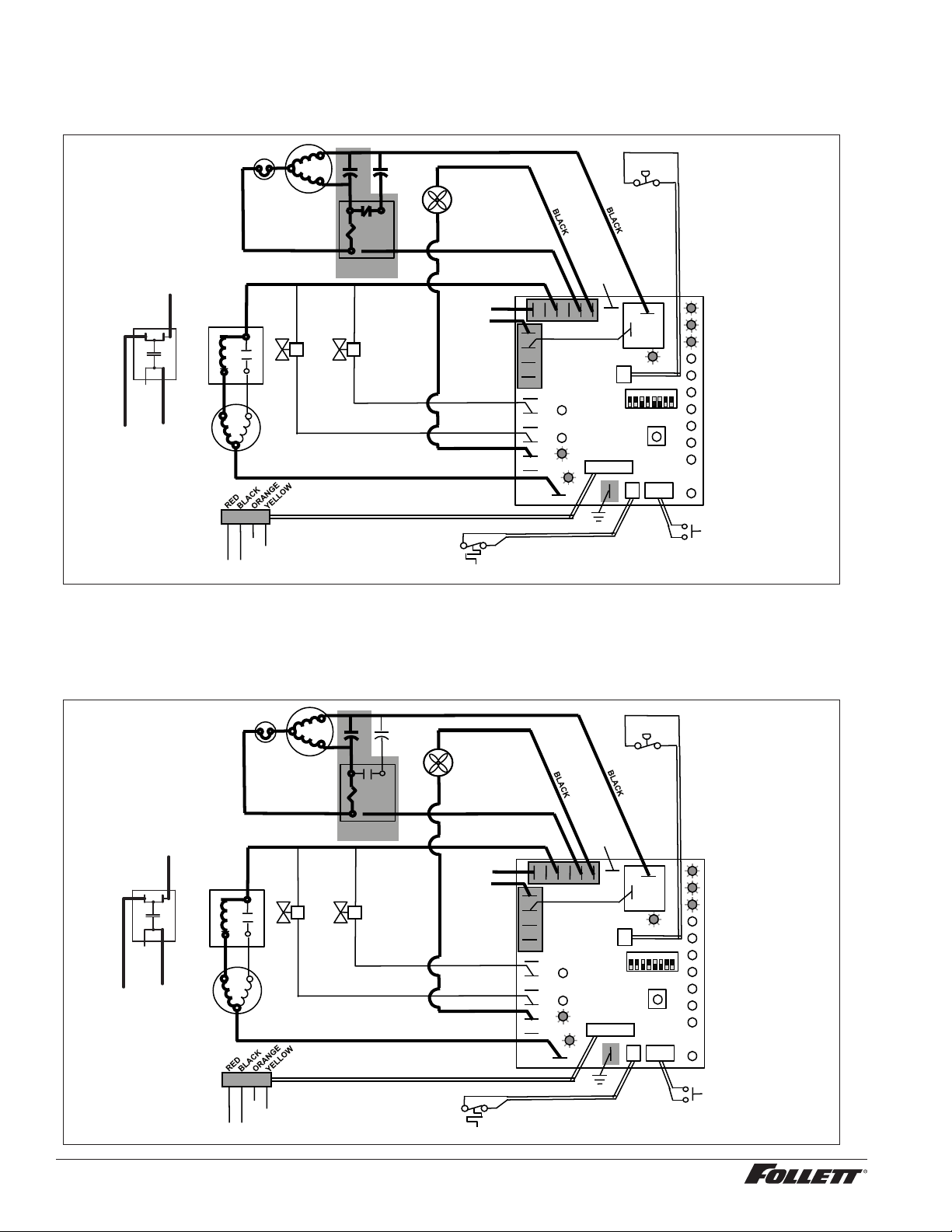
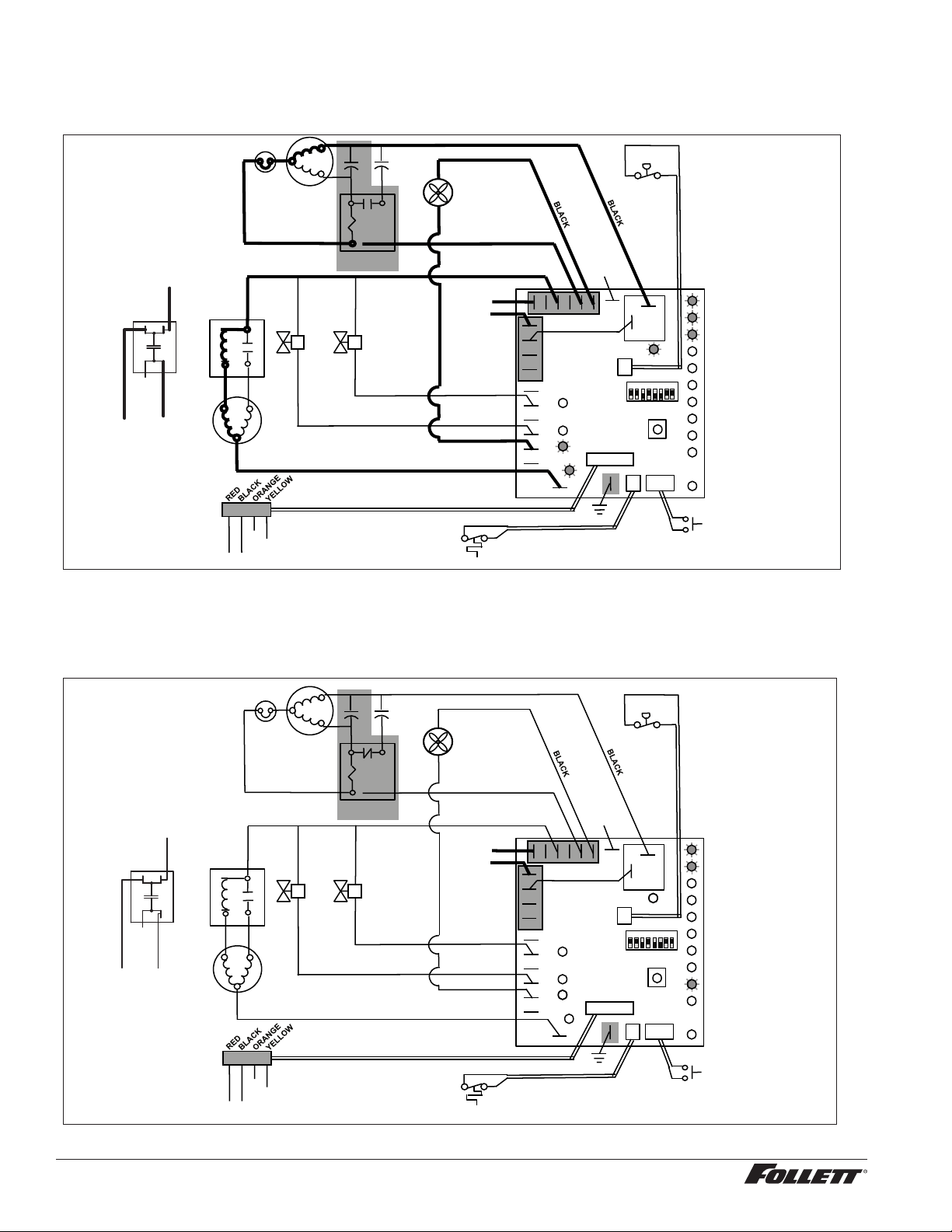
Normal operation – Stage 4
One second (1 s) after the fan comes on, the COMPRESSOR output comes on. The compressor circuit uses both
run and start capacitors along with a potential start relay. The start capacitor in energized through the normally
closed contacts of the start relay.
5
2
1
Start
Run
Compressor
T.O.L.
MAINTENANCE
LOW WATER
TIME DELAY
SLEEP CYCLE
MAKING ICE
LOW BIN
POWER
SERVICE
HI AMPS
HI PRESSURE
CLEANER FULL
High
Pressure
Switch
R
S
C
Gearmotor
Start
Relay
Start
Relay
N
L1
Fan
A B C D
Water Sensors
RESET
Fill
Valve
Drain
Valve
3
4
2
Bin T-Stat
Clean Switch
P6
P21
P20
P19
P3
P22
P4
AUGER
WATER LEVELS
BIN
P11
HI PRS
L1
R
S
C
RED
WHITE
WHITE
BLACK
BROWN
BLUE
RED
BLACK YELLOW
Compressor
Electrical Box
COMPRESSOR
1 2 3 4 5 6 7 8
BLACK
N
P15
Ice Dispense Input
OR
Capacitor
BLACK
YELLOW
NO CONNECT
Normal operation – Stage 5
As the compressor comes up to normal running speed, its start winding generates a voltage potential across the
relay’s coil. This energizes the coil to open the contact and drop out the start capacitor.
The ice machine is now in a normal ice making mode. The ice machine will produce ice until the bin level control in
the ice dispenser is satised.
5
2
1
Start
Run
Compressor
T.O.L.
MAINTENANCE
LOW WATER
TIME DELAY
SLEEP CYCLE
MAKING ICE
LOW BIN
POWER
SERVICE
HI AMPS
HI PRESSURE
CLEANER FULL
High
Pressure
Switch
R
S
C
Gearmotor
Start
Relay
Start
Relay
N
L1
Fan
A B C D
Water Sensors
RESET
Fill
Valve
Drain
Valve
3
4
2
Bin T-Stat
Clean Switch
P6
P21
P20
P19
P3
P22
P4
AUGER
WATER LEVELS
BIN
P11
HI PRS
L1
R
S
C
RED
WHITE
WHITE
BLACK
BROWN
BLUE
RED
BLACK YELLOW
Compressor
Electrical Box
COMPRESSOR
1 2 3 4 5 6 7 8
BLACK
N
P15
Ice Dispense Input
OR
Capacitor
BLACK
YELLOW
NO CONNECT
26 12CI425A, 12HI425A
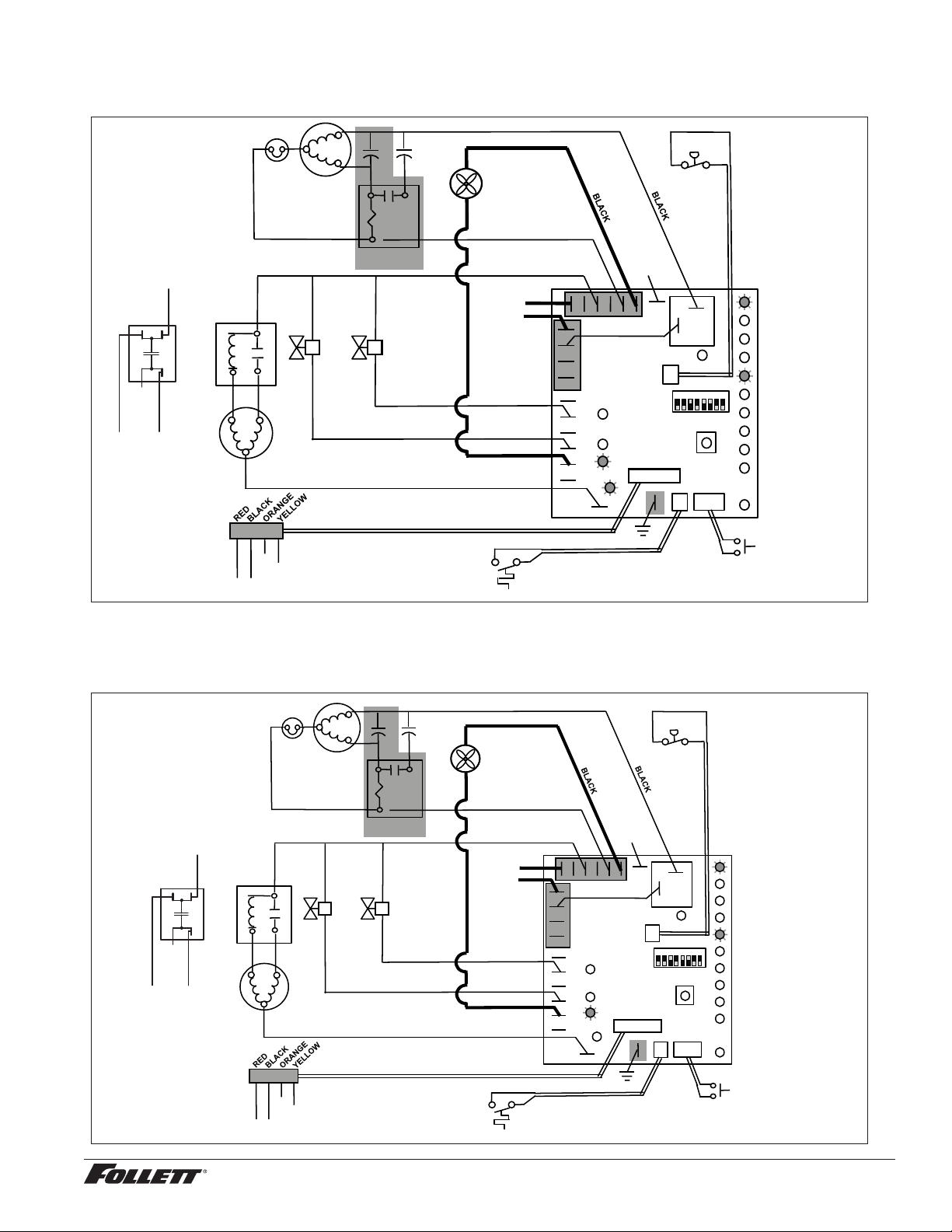
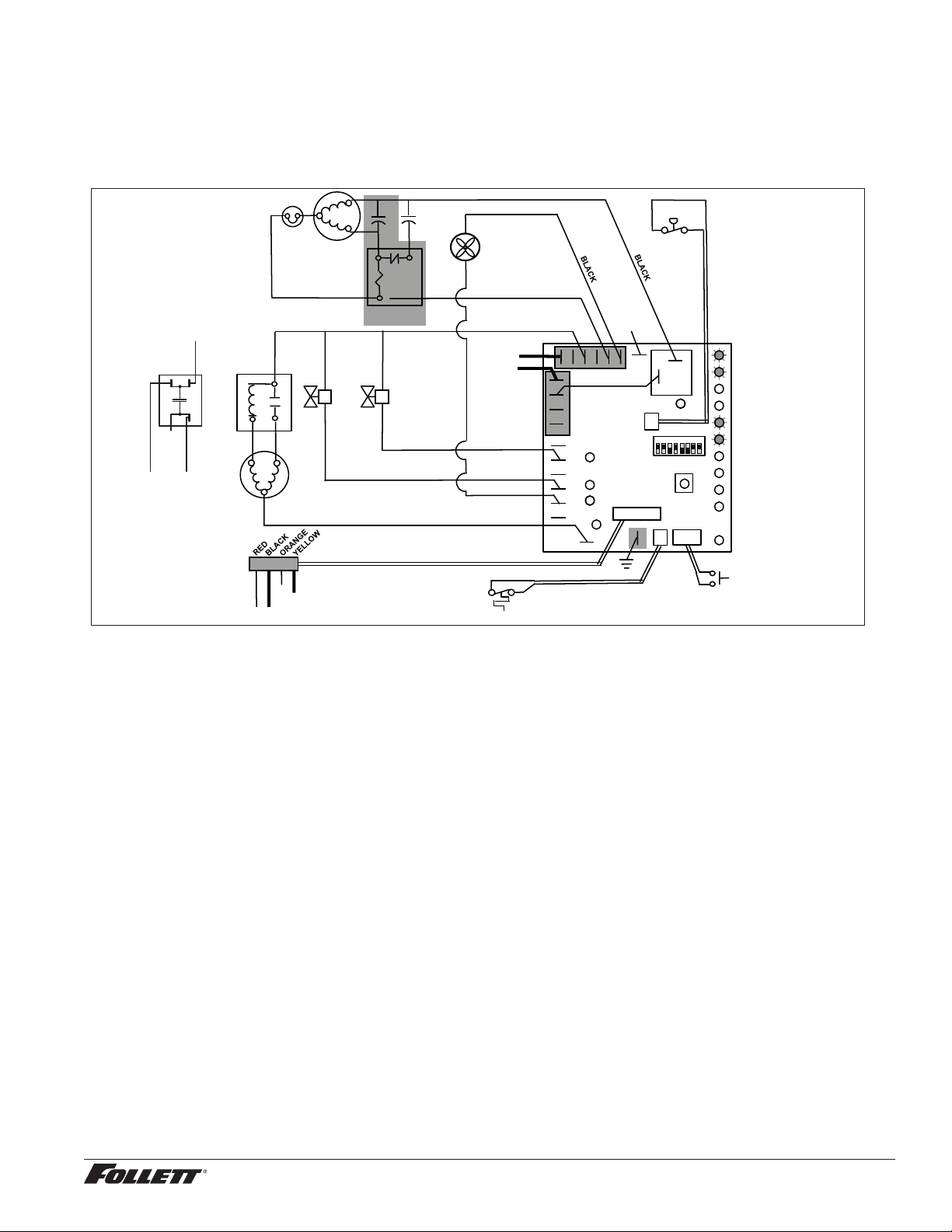
Normal operation – Stage 6
Once the bin thermostat control opens, the LOW BIN LED goes out. After a 10 second delay the compressor
output turns off, the MAKING ICE LED goes out and the TIME DELAY LED comes on.
5
2
1
Start
Run
Compressor
T.O.L.
MAINTENANCE
LOW WATER
TIME DELAY
SLEEP CYCLE
MAKING ICE
LOW BIN
POWER
SERVICE
HI AMPS
HI PRESSURE
CLEANER FULL
High
Pressure
Switch
R
S
C
Gearmotor
Start
Relay
Start
Relay
N
L1
Fan
A B C D
Water Sensors
RESET
Fill
Valve
Drain
Valve
3
4
2
Bin T-Stat
Clean Switch
P6
P21
P20
P19
P3
P22
P4
AUGER
WATER LEVELS
BIN
P11
HI PRS
L1
R
S
C
RED
WHITE
WHITE
BLACK
BROWN
BLUE
RED
BLACK YELLOW
Compressor
Electrical Box
COMPRESSOR
1 2 3 4 5 6 7 8
BLACK
N
P15
Ice Dispense Input
Capacitor
BLACK
YELLOW
OR
NO CONNECT
Normal operation – Stage 7
The fan motor continues for 10 minutes before shutting off. The TIME DELAY LED remains on for 20 minutes.
The ice machine will not start while the TIME DELAY LED is on. To restart the ice machine for troubleshooting
purposes, depress the reset button to clear the control board.
5
2
1
Start
Run
Compressor
T.O.L.
MAINTENANCE
LOW WATER
TIME DELAY
SLEEP CYCLE
MAKING ICE
LOW BIN
POWER
SERVICE
HI AMPS
HI PRESSURE
CLEANER FULL
High
Pressure
Switch
R
S
C
Gearmotor
Start
Relay
Start
Relay
N
L1
Fan
A B C D
Water Sensors
RESET
Fill
Valve
Drain
Valve
3
4
2
Bin T-Stat
Clean Switch
P6
P21
P20
P19
P3
P22
P4
AUGER
WATER LEVELS
BIN
P11
HI PRS
L1
R
S
C
RED
WHITE
WHITE
BLACK
BROWN
BLUE
RED
BLACK YELLOW
Compressor
Electrical Box
COMPRESSOR
1 2 3 4 5 6 7 8
BLACK
N
P15
Ice Dispense Input
OR
Capacitor
BLACK
YELLOW
NO CONNECT
12CI425A, 12HI425A 27
Normal operation – Stage 8
When the dwell time of 20 minutes has expired, the TIME DELAY LED goes off. If 5 seconds of ice has been
dispensed and the SLEEP CYCLE LED (Symphony Plus only) is off, the ice machine will go through the normal
start-up sequence when the bin level control signals the control board for ice.
5
2
1
Start
Run
Compressor
T.O.L.
MAINTENANCE
LOW WATER
TIME DELAY
SLEEP CYCLE
MAKING ICE
LOW BIN
POWER
SERVICE
HI AMPS
HI PRESSURE
CLEANER FULL
High
Pressure
Switch
R
S
C
Gearmotor
Start
Relay
Start
Relay
N
L1
Fan
A B C D
Water Sensors
RESET
Fill
Valve
Drain
Valve
3
4
2
Bin T-Stat
Clean Switch
P6
P21
P20
P19
P3
P22
P4
AUGER
WATER LEVELS
BIN
P11
HI PRS
L1
R
S
C
RED
WHITE
WHITE
BLACK
BROWN
BLUE
RED
BLACK YELLOW
Compressor
Electrical Box
COMPRESSOR
1 2 3 4 5 6 7 8
BLACK
N
P15
Ice Dispense Input
OR
Capacitor
BLACK
YELLOW
NO CONNECT
Quiet Night™/Sleep cycle (Symphony Plus only)
The board monitors ice dispensing through a line voltage input to P15. If the ice dispense has not be initiated for
more than 5 seconds during the 20 minute time delay, the SLEEP CYCLE LED comes on. The machine will stay off
for 12 hours unless 5 seconds of dispensing is seen. After 12 hours, the SLEEP CYCLE LED goes out and the ice
making will resume if the bin thermostat is closed. The sleep cycle dispense duration is adjustable using the DIP
switches on the control board.
Self-ushing (when enabled)
At the completion of the 20 minute time delay, the machine checks for a cumulative one hour of ice making time
since the last off-cycle ush. If the cumulative ice making time exceeds one hour, the machine will energize the
drain valve P19 for 60 seconds to drain the evaporator. It will then rell with water, ush again, rell and begin
making ice if the LOW BIN LED is on. If the ice making time is less than 1 hour, the machine will start and begin
making ice without draining the evaporator.
28 12CI425A, 12HI425A
5
2
1
Start
Run
Compressor
T.O.L.
MAINTENANCE
LOW WATER
TIME DELAY
SLEEP CYCLE
MAKING ICE
LOW BIN
POWER
SERVICE
HI AMPS
HI PRESSURE
CLEANER FULL
High
Pressure
Switch
R
S
C
Gearmotor
Start
Relay
Start
Relay
N
L1
Fan
A B C D
Water Sensors
RESET
Fill
Valve
Drain
Valve
3
4
2
Bin T-Stat
Clean Switch
P6
P21
P20
P19
P3
P22
P4
AUGER
WATER LEVELS
BIN
P11
HI PRS
L1
R
S
C
RED
WHITE
WHITE
BLACK
BROWN
BLUE
RED
BLACK YELLOW
Compressor
Electrical Box
COMPRESSOR
1 2 3 4 5 6 7 8
BLACK
N
P15
Ice Dispense Input
OR
Capacitor
BLACK
YELLOW
NO CONNECT
Diagnostic stages
High gearmotor amps – Stage 1
The HI AMPS error and TIME DELAY LEDs are on indicating that the control board has sensed an over-torque
condition at the P4 terminal (more than 3 amps from the gearmotor) or no current draw (0A) and shut the ice
machine down (strike one). The HI AMPS and TIME DELAY LEDs will remain on for 60 minutes after an over-
torque condition has occurred. The ice machine will remain off as long as these two LEDs are on. After the
60 minute time delay, these LED lights turn off, and the control board will try to go through a normal start-up
sequence.
5
2
1
Start
Run
Compressor
T.O.L.
MAINTENANCE
LOW WATER
TIME DELAY
SLEEP CYCLE
MAKING ICE
LOW BIN
POWER
SERVICE
HI AMPS
HI PRESSURE
CLEANER FULL
High
Pressure
Switch
R
S
C
Gearmotor
Start
Relay
Start
Relay
N
L1
Fan
A B C D
Water Sensors
RESET
Fill
Valve
Drain
Valve
3
4
2
Bin T-Stat
Clean Switch
P6
P21
P20
P19
P3
P22
P4
AUGER
WATER LEVELS
BIN
P11
HI PRS
L1
R
S
C
RED
WHITE
WHITE
BLACK
BROWN
BLUE
RED
BLACK YELLOW
Compressor
Electrical Box
COMPRESSOR
1 2 3 4 5 6 7 8
BLACK
N
P15
Ice Dispense Input
OR
Capacitor
BLACK
YELLOW
NO CONNECT
12CI425A, 12HI425A 29
High gearmotor amps – Stage 2
If the restart is successful the board will continue to monitor the current draw on P4 for 60 minutes looking for
a second high amps (above 3A) occurrence. If the ice machine runs without problems for 60 minutes and no
additional torque errors occur, the ice machine will continue normal operation.
5
2
1
Start
Run
Compressor
T.O.L.
MAINTENANCE
LOW WATER
TIME DELAY
SLEEP CYCLE
MAKING ICE
LOW BIN
POWER
SERVICE
HI AMPS
HI PRESSURE
CLEANER FULL
High
Pressure
Switch
R
S
C
Gearmotor
Start
Relay
Start
Relay
N
L1
Fan
A B C D
Water Sensors
RESET
Fill
Valve
Drain
Valve
3
4
2
Bin T-Stat
Clean Switch
P6
P21
P20
P19
P3
P22
P4
AUGER
WATER LEVELS
BIN
P11
HI PRS
L1
R
S
C
RED
WHITE
WHITE
BLACK
BROWN
BLUE
RED
BLACK YELLOW
Compressor
Electrical Box
COMPRESSOR
1 2 3 4 5 6 7 8
BLACK
N
P15
Ice Dispense Input
OR
Capacitor
BLACK
YELLOW
NO CONNECT
High gearmotor amps – Stage 3
If a second occurrence happens during the 60 minute monitoring period, the HI AMPS LED will come on again
and shut the machine down (strike two). The HI AMPS LED (without the TIME DELAY LED) will indicate to the
technician that two consecutive over-torque situations have occurred. The ice machine is shut down at this time
and locked out. It will not restart unless the manual reset button is depressed while power is on.
5
2
1
Start
Run
Compressor
T.O.L.
MAINTENANCE
LOW WATER
TIME DELAY
SLEEP CYCLE
MAKING ICE
LOW BIN
POWER
SERVICE
HI AMPS
HI PRESSURE
CLEANER FULL
High
Pressure
Switch
R
S
C
Gearmotor
Start
Relay
Start
Relay
N
L1
Fan
A B C D
Water Sensors
RESET
Fill
Valve
Drain
Valve
3
4
2
Bin T-Stat
Clean Switch
P6
P21
P20
P19
P3
P22
P4
AUGER
WATER LEVELS
BIN
P11
HI PRS
L1
R
S
C
RED
WHITE
WHITE
BLACK
BROWN
BLUE
RED
BLACK YELLOW
Compressor
Electrical Box
COMPRESSOR
1 2 3 4 5 6 7 8
BLACK
N
P15
Ice Dispense Input
OR
Capacitor
BLACK
YELLOW
NO CONNECT
30 12CI425A, 12HI425A
Loss of water
During operation, the water level cycles between the normal low (D) and normal high (C) water probes - the ll
valve (P21) cycling on and off. If continuity is not detected between the common probe (B) and normal low (D)
within 10 seconds, the LOW WATER and TIME DELAY LEDs will come on and the machine will shut down for
the one hour time delay period. After the time delay, the ll valve will re-energize and wait for continuity between
the common probe and normal high before restarting. LOW WATER LED will remain ON until the water level is
satised.
5
2
1
Start
Run
Compressor
T.O.L.
MAINTENANCE
LOW WATER
TIME DELAY
SLEEP CYCLE
MAKING ICE
LOW BIN
POWER
SERVICE
HI AMPS
HI PRESSURE
CLEANER FULL
High
Pressure
Switch
R
S
C
Gearmotor
Start
Relay
Start
Relay
N
L1
Fan
A B C D
Water Sensors
RESET
Fill
Valve
Drain
Valve
3
4
2
Bin T-Stat
Clean Switch
P6
P21
P20
P19
P3
P22
P4
AUGER
WATER LEVELS
BIN
P11
HI PRS
L1
R
S
C
RED
WHITE
WHITE
BLACK
BROWN
BLUE
RED
BLACK YELLOW
Compressor
Electrical Box
COMPRESSOR
1 2 3 4 5 6 7 8
BLACK
N
P15
Ice Dispense Input
OR
Capacitor
BLACK
YELLOW
NO CONNECT
12CI425A, 12HI425A 31
High refrigerant pressure
Should the refrigeration pressure rise above 425 psi, the high pressure switch contacts will open. The board sees
the open circuit and the HIGH PRESSURE and TIME DELAY LEDs will come on, the machine shuts down. After
the one hour time delay, the machine will attempt to restart. If the pressure has fallen below the reset point of 295
psi and the board see the contacts closed, the machine will resume normal operation. If the contacts are still open
after the restart, the board will again go into HIGH PRESSURE and TIME DELAY, cycling until contact closure is
seen.
5
2
1
Start
Run
Compressor
T.O.L.
MAINTENANCE
LOW WATER
TIME DELAY
SLEEP CYCLE
MAKING ICE
LOW BIN
POWER
SERVICE
HI AMPS
HI PRESSURE
CLEANER FULL
High
Pressure
Switch
R
S
C
Gearmotor
Start
Relay
Start
Relay
N
L1
Fan
A B C D
Water Sensors
RESET
Fill
Valve
Drain
Valve
3
4
2
Bin T-Stat
Clean Switch
P6
P21
P20
P19
P3
P22
P4
AUGER
WATER LEVELS
BIN
P11
HI PRS
L1
R
S
C
RED
WHITE
WHITE
BLACK
BROWN
BLUE
RED
BLACK YELLOW
Compressor
Electrical Box
COMPRESSOR
1 2 3 4 5 6 7 8
BLACK
N
P15
Ice Dispense Input
OR
Capacitor
BLACK
YELLOW
NO CONNECT
32 12CI425A, 12HI425A
Refrigeration system
Important: All service on refrigeration system must be performed in accordance with all federal, state and local
laws that pertain to the use of refrigerants. It is the responsibility of the technician to ensure that these requirements
are met.
Refrigeration cycle
high side
service port
filter dryer
condenser
low side service port
high pressure
switch
compressor
evaporator
thermostatic
expansion
valve
high
pressure
vapor
high
pressure
liquid
low
pressure
vapor
low
pressure
liquid
Refrigeration pressure data
Ambient Air Temperature ˚F/˚C
Inlet Water Temperature ˚F/˚C
F
C
50
10
60
16
70
21
80
27
90
32
60
16
460
208
437
198
415
188
405
184
395
179
70
21
425
193
405
184
385
175
375
170
365
166
80
27
390
177
372
169
355
161
345
156
335
152
90
32
355
161
340
154
325
147
315
142
305
138
100
38
320
145
307
139
295
134
285
129
275
125
lbs.
kg.
lbs.
kg.
lbs.
kg.
lbs.
kg.
lbs.
kg.
Air-cooled ice machine capacity/24 hrs.
Compressor data
Compressor current draw
Air-cooled
Air temp (F) 60 70 80 90 100
Comp Amperage (A) 5.8 6.1 6.2 6.2 6.3
High-side Pressure
(psi)
190 220 250 290 330
Low-side Pressure (psi) 27 29 31 33 36
Locked rotor amps 58.8A
Gearmotor data Split-Phase PSC (permanent split capacitor)
Gearmotor current 1.8A-1.9A (nominal) 0.8A-0.9A (nominal)
Locked rotor amps 14A 7A-14A (temperature dependent)
12CI425A, 12HI425A 33
R425 ice machine charge specications
Model Charge Refrigerant type
12CI425A, 12HI425A (air-cooled) 15 oz R404A
CAUTION!
§ Recharging of unit at other than factory specications will void ice machine warranty.
Refrigerant replacement requirements
1. Non-contaminated refrigerant removed from any Follett refrigeration system can be recycled and returned
to the same system after completing repairs. Recycled refrigerant must be stored in a clean, approved
storage container. If additional refrigerant is required, virgin or reclaimed refrigerant that meets ARI
standard 700-88 must be used.
2. In the event of system contamination (for example, a compressor burn out, refrigerant leak, presence of
non-condensibles or moisture), the system must be repaired, evacuated and recharged using virgin or
reclaimed refrigerant that meets ARI standard 700-88.
3. Follett Corporation does not approve of recovered refrigerants. Improper refrigeration servicing
procedures will void the factory warranty.
Evacuation
Evacuate the system to a level of 500 microns. When the 500 micron level is reached, close valves and both
manifold and shut down the vacuum pump. Allow the system to sit for approximately 20 minutes. During this period
the system pressure should not rise. If the system pressure rises and stabilizes there is moisture in the system and
further evacuation is needed. If the pressure continues to rise check the system for leaks.
Ice capacity test
Ice machine production capacity can only be determined by weighing ice produced in a specic time period.
1. Remove top panel and hopper lid of unit.
2. Weigh and record weight of container used to catch ice.
3. Run ice machine for at least 15 minutes.
4. Catch ice for 15 or 20 minutes.
5. Weigh harvested ice and record total weight.
6. Subtract weight of container from total weight.
7. Convert fractions of pounds to decimal equivalents (Ex. 6 lbs 8 oz = 6.5 lbs).
8. Calculate production using following formula:
1440 min. x wt. of ice produced
= Production capacity/24 hr. period
Total test time in minutes
9. Calculated amount per 24 hours should be checked against rated capacity for same ambient and
water temperatures in Ice Production Table (see page 31).
34 12CI425A, 12HI425A
Dispenser troubleshooting
CAUTION!
§ Disconnect power to unit before putting hands or arms in storage area or attempting any repair or service to
equipment.
Before calling for service
1. Check that no ice is in the dispenser bin area.
2. Check that congealed ice is not causing a jam
3. Check that all switches and circuit breakers are on
4. Check that all drains are clear.
5. Check water is supplied.
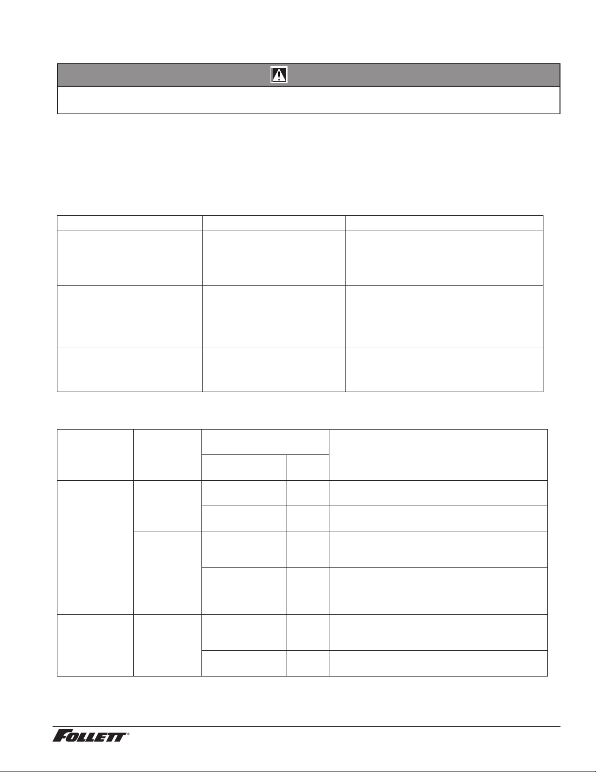
Lever model troubleshooting guide
Problem Indicators Corrective Action
Does not dispense ice. 1. Power switch off or faulty.
2. Faulty dispense switch.
3. Wheel motor malfunction.
1. Check switch – turn on or replace if
faulty.
2. Replace switch.
3. Check motor and replace
Dispense wheel rotates
continuously.
Dispense switch contacts are
burned out.
Replace dispense switch.
Ice machine runs continuously. Faulty or incorrectly positioned
bin stat.
Check for proper positioning. If stat does
not open when ice is placed on capillary
tube, replace stat.
Does not dispense water. 1. Faulty water solenoid valve.
2. Faulty dispense switch.
3. Power switch off or faulty.
1. Replace water solenoid valve.
2. Replace dispense switch.
3. Check switch - turn on or replace if faulty.
SensorSAFE model troubleshooting guide
Problem Action
SensorSAFE Board LED
Status
Corrective ActionPWR CLN
ICE/
WTR
Does not
dispense ice
and/or water.
Check
LEDs on the
SensorSAFE
control board.
OFF OFF OFF Check circuit breakers and power switch.
Restore power or replace defective switch.
ON ON OFF Press clean switch on lower left side of electrical
enclosure to return board to normal operation.
Place cup
under drop
zone (in front
of lens)
ON OFF OFF Troubleshoot appropriate lens/sensor
and replace if required (see lens/sensor
troubleshooting).
ON OFF ON Verify power on appropriate output terminal
(WTR or WM) on control board and replace
board if required. If board tests okay,
troubleshoot appropriate dispenser component.
Dispenses ice
and/or water
continuously.
Check LEDs
on control
board.
ON OFF ON Troubleshoot appropriate lens/sensor
and replace if required (see lens/sensor
troubleshooting).
ON OFF OFF If there is power on any output terminal 9WTR
or WM) on control board, replace board.
12CI425A, 12HI425A 35
SensorSAFE board guide
LEDs, when illuminated, indicate the following: PWR
(board power), CLN (clean button pressed WTR and
WM outputs disabled), ICE (ice dispensing activated),
WTR (water dispensing activated).
Terminals: L1 (incoming power, hot), L2 (neutral
terminals), WTR (power terminal for water solenoid),
WM (power terminal for wheelmotor), CLN (terminals
for clean cycle switch).
Note: SOL terminal not used in 12 series dispensers.
Fig. 17
SOL
WTR
NEUTRAL
CLN
WM
PWR
WTR
L1
GND
ICE
Lens/sensor troubleshooting
1. Turn dispenser power switch off and remove splash panel.
2. Disconnect wires from WTR and WM terminals on board.
3. Gently remove sensor/mounting block from splash panel.
4. Inspect lens and sensor, clean if necessary.
5. Restore dispenser power and test sensor by passing hand in front of sensor.
6. If LED on board turns on, sensor is operational. Re-assemble dispenser.
7. If LED does not come on switch sensor leads on board and retest.
8. If opposite LED comes on – replace defective board.
9. If opposite LED does not come on – replace defective sensor.
Disassembly and replacement instructions
Dispense wheel removal
1. Remove all ice from storage area of
dispenser.
2. Remove center thumbscrew (Fig. 18.1),
locking plate (Fig. 18.2), two wingnuts (Fig.
18.3) and backing plate (Fig. 18.4) from
front of storage hopper (see drawing at
right).
3. Remove threaded rod (Fig. 18.5), agitator
(Fig. 18.6), baffle (Fig. 18.7), and wheel
(Fig. 18.8) in this sequence.
Wheelmotor removal
1. Remove dispense wheel.
2. Remove four (4) dispenser motor bracket
mounting screws and washers (Fig. 19.1).
3. Remove (4) screws holding motor to
mounting bracket (Fig. 19.2).
Fig. 18
7
5
1
6
4
3
2
1
1
8
36 12CI425A, 12HI425A
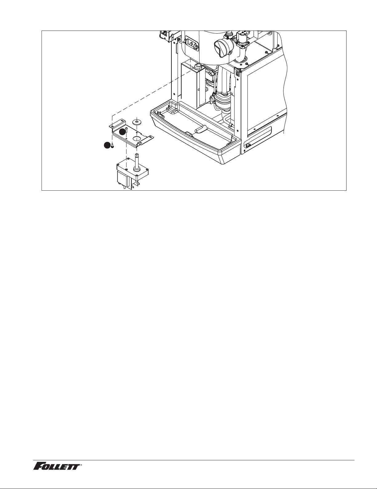
Fig. 19
1
2
12CI425A, 12HI425A 37
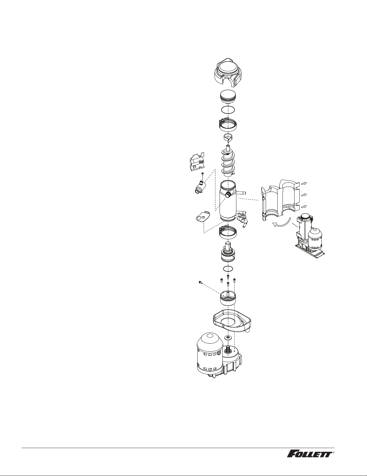
Evaporator disassembly
Note: The upper bearing, lower bearing and auger assemblies must be replaced as assemblies. The bottom and
top bearing assemblies cannot be eld assembled to factory specications.
1. Press CLEAN switch.
2. Wait for LOW WATER light to illuminate.
3. Turn OFF power.
4. Remove top bearing insulation.
5. Remove compression nozzle insulation.
6. Disconnect vent and drain tube from nozzle.
7. Disconnect compression nozzle from
evaporator.
8. Disconnect evaporator water feed line.
9. Remove nut and upper vee band coupling
from top of evaporator.
10. Lift top bearing assembly straight up with a
slight rotating motion and remove.
11. Remove ice compression loop located at
top of auger.
12. Lift auger straight up and out of evaporator.
13. Remove nut and lower vee band coupling
from bottom of evaporator.
14. Lift evaporator to clear bottom bearing
assembly.
15. Loosen hex head bolt in side of mounting
base with 5/16 wrench and lift lower bearing
assembly.
16. Remove condensate shield.
1 7. Remove 4 Allen head machine screws
holding mounting base to gearbox.
Fig. 20
38 12CI425A, 12HI425A
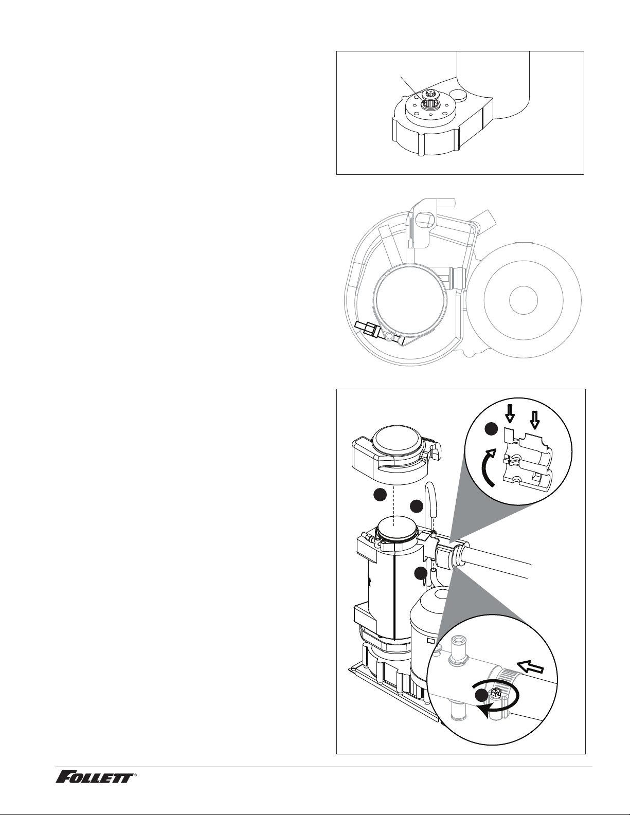
Evaporator reassembly
1. Clean gearmotor boss, output shaft and
shaft well.
2. Install drain pan and evaporator mounting
base.
3. Fill gearmotor shaft well with food grade
grease (Fig. 21).
4. Install condensate shield and seat against
gearmotor boss.
5. Install bearing O ring in groove in
evaporator mounting base.
Fig. 21
Apply grease in well
Evaporator drain pan and mounting base not shown for clarity.
6. While maintaining rm downward pressure
on bottom bearing assembly, tighten hex
head bolt with a 5/16 wrench.
7. Position evaporator over lower bearing
assembly and align grooves with pins in
bearing assembly.
8. Install vee band clamp and nut to 70 in/lb.
(Fig. 22).
Note: Clamp must be oriented as shown
in order for the insulation to be placed
properly.
9. Place auger in center of evaporator and
rotate to mate with drive pin.
10. Install ice compression loop, orienting loop.
11. Install upper bearing and seal assembly,
rotating bearing to slip pin into auger slot.
12. Install upper vee band clamp and nut to 70
in/lb.
13. Install compression nozzle and tubing.
14. Secure ice transport tube with clamp
(Fig.23.1).
Note: Clamp must be oriented as shown
in order for the insulation to be placed
properly.
15. Install compression nozzle insulation
(Fig.23.2).
16. Install vent and drain tube (Fig.23.3).
1 7. Install top bearing insulation (Fig.23.4).
Gearmotor replacement
1. Disassemble evaporator.
2. Disconnect the wire connectors.
3. Remove 4 screws holding gearmotor
mounting plate to base of ice machine and
lift gearbox and motor clear of ice machine.
4. Remove machine screws holding mounting
plate to motor.
5. Install new motor in reverse order.
Fig. 22
Fig. 23
4
3
3
1
2
12CI425A, 12HI425A 39
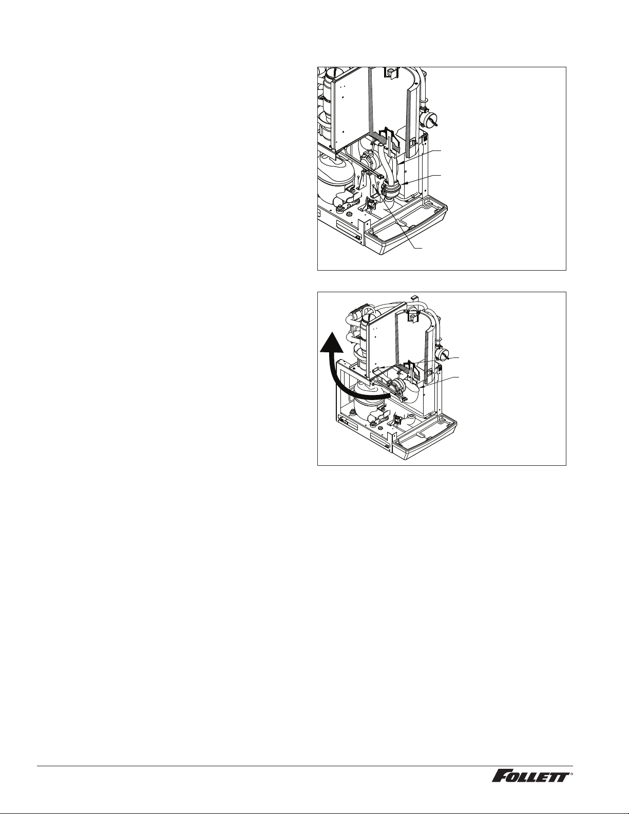
Fan removal
1. Remove 4 fan mounting screws and 3 drain
tubes from bracket.
Fig. 24
REMOVE DRAIN TUBES
FROM DRAIN CAP.
REMOVE DRAIN CUP
AND CAP.
REMOVE FAN BASE
MOUNTING SCREWS.
2. Rotate fan mounting bracket toward back of unit
and pull fan assembly toward front of unit.
Fig. 25
ROTATE BASE OF FAN
TOWARDS BACK OF UNIT.
MOVE FAN AWAY FROM
CONDENSER.
MOVE FAN TOWARDS
FRONT OF UNIT TO
COMPLETE REMOVAL.
40 12CI425A, 12HI425A
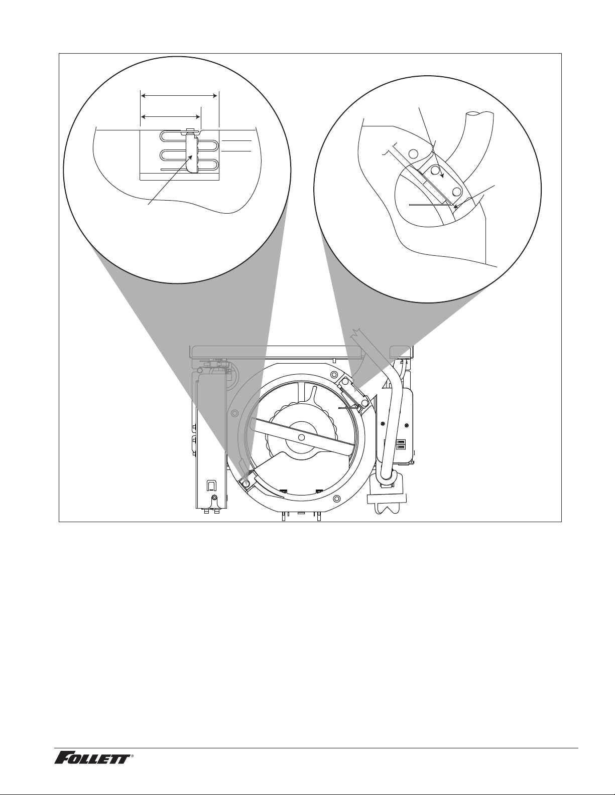
Thermostat and ice transport tube replacement
.25
ice tube
gasket
ice tube
retainer
3" (76 mm)
0.50 TYP
2" (51 mm)
capillary
tube
bracket
Thermostat: hand bend cap tube end as shown
Ice transport tube: tube may
extend a maximum
of 1/4" (6 mm) into ice bin
Ice transport tube replacement
1. Refer to Fig. 23.
12CI425A, 12HI425A 41
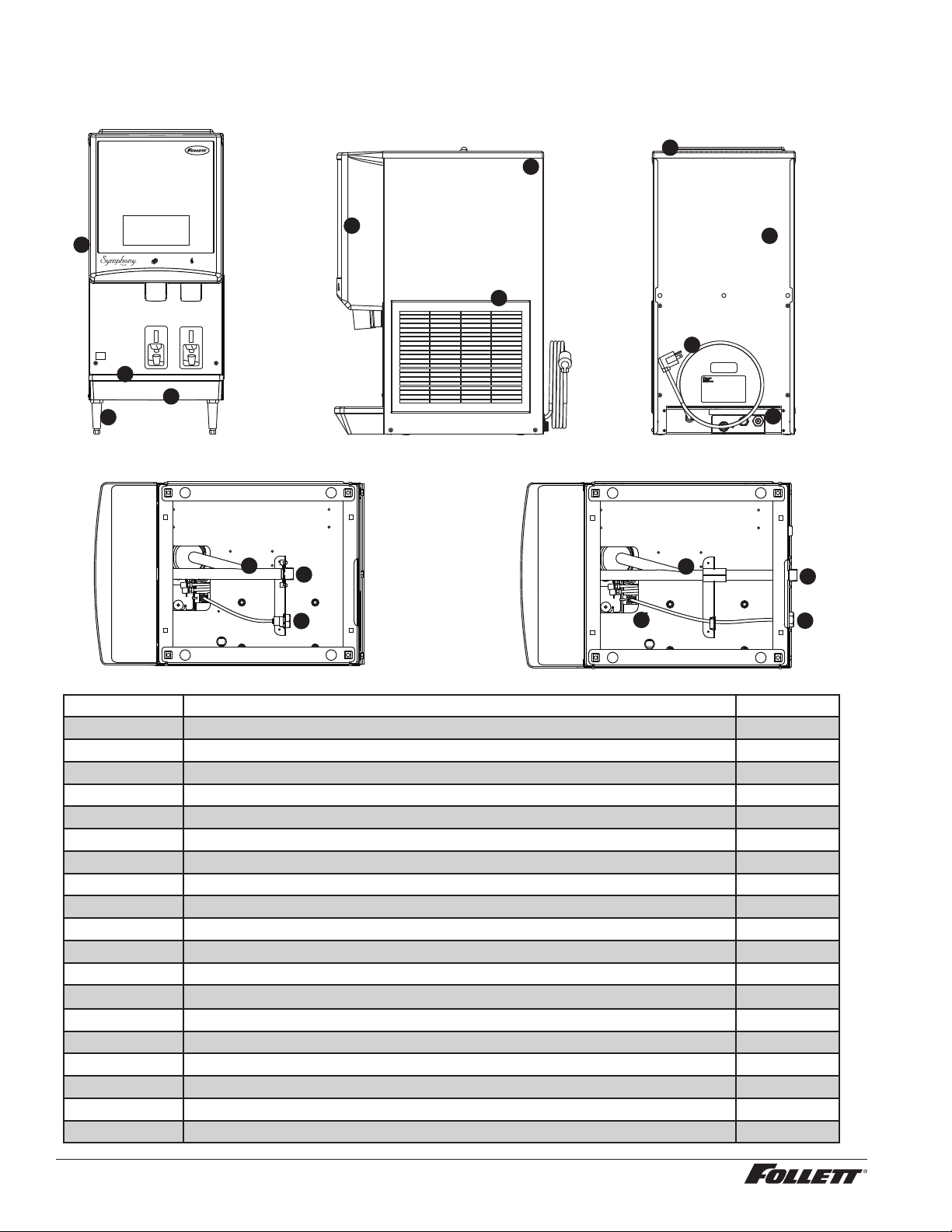
Replacement parts
Dispenser exterior
10
9
2
1
14
5
13
3
4
1
6
11
11
7
12
7
12
7
8
Reference # Description Part #
1 Cover, front, ice and water 01064575
Not shown Cover, front, ice only 01064583
2 Louver, intake, plastic 00967117
Not shown Grille, drain pan, gray plastic 01051614
3 Drain pan, plastic 00967059
4 Drain pan assembly (includes hardware, pan and grille) 502410
5 Panel, rear 01220904
6 Leg kit, 4" (10.2 cm), adjustable – set of 4 502399
7 Fitting, water inlet, brass 3/8" FPT x 1/4" john guest 01065275
8 Lid, top panel, plastic 00967091
9 Panel, right side 01220888
10 Panel, left side 01220896
11 Tube, drain pan/collector cup 01065390
12 Fitting, drain 00109728
13 Valve, 1/4" john guest 01035526
14 Cord and plug, power 01035682
Not shown Bracket, wall 16" (40.6 cm) 502873
Not shown Clip, valve 01035534
Not shown Grille, drain pan - case of 12 01071224
42 12CI425A, 12HI425A
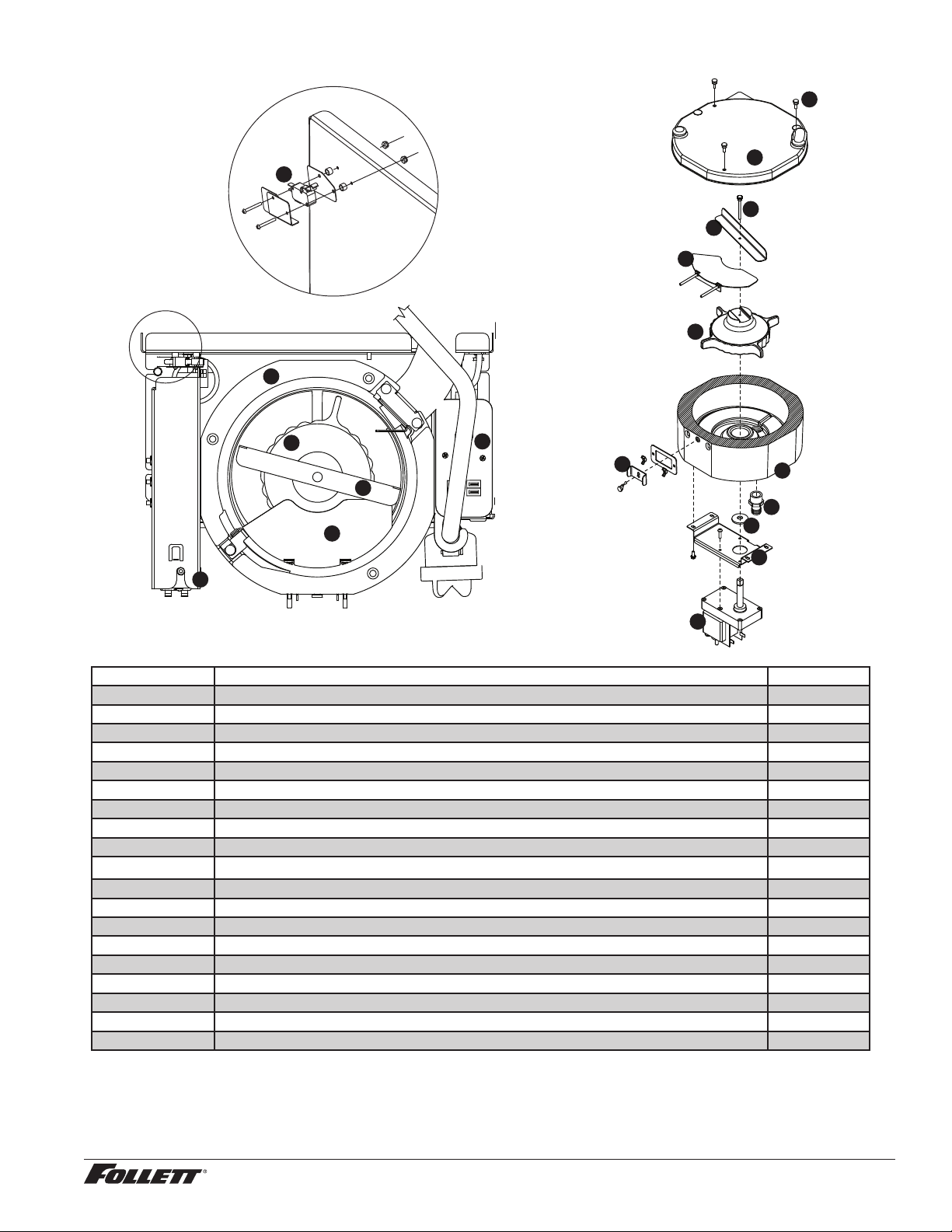
Wheelmotor and drive system
12
13
4
5
2
3
14
8
6
1
9
3
6
7
5
2
11
15
10
Reference # Description Part #
1 Motor, wheel, long shaft (includes gear motor shield) 502580
2 Baffle, ice (securing hardware, part# 00167973, included) 502414
3 Wheel with Agion, agitator 502387
4 Rod, threaded (includes knurled nut) 502390
5 Agitator, rotating 502386
See page 41 Bracket, capillary tube 502406
See page 41 Retainer, ice tube 00977314
See page 41 Gasket, ice tube 00977322
6 Assembly, hopper with Agion (includes drain tting) 502413
7
Reservoir body (includes fasteners) 01230622
8 Fitting, hopper drain, 3/4 MPT, 3/4" barb tting 207095
9 Switch, interlock 502416
10 Support plate, motor 502423
11 Cover, electrical box 502408
12 Screws, 10-32 x 1/2 (6 needed) 201022
13 Hopper lid with hopper lid safety switch actuation 00951541
Not shown Hopper lid, dispenser top cover, safety switch actuation (Before SN# B72959) 207809
14 Hardware, baffle securing 00167973
15 Shield, gear motor 502537
12CI425A, 12HI425A 43
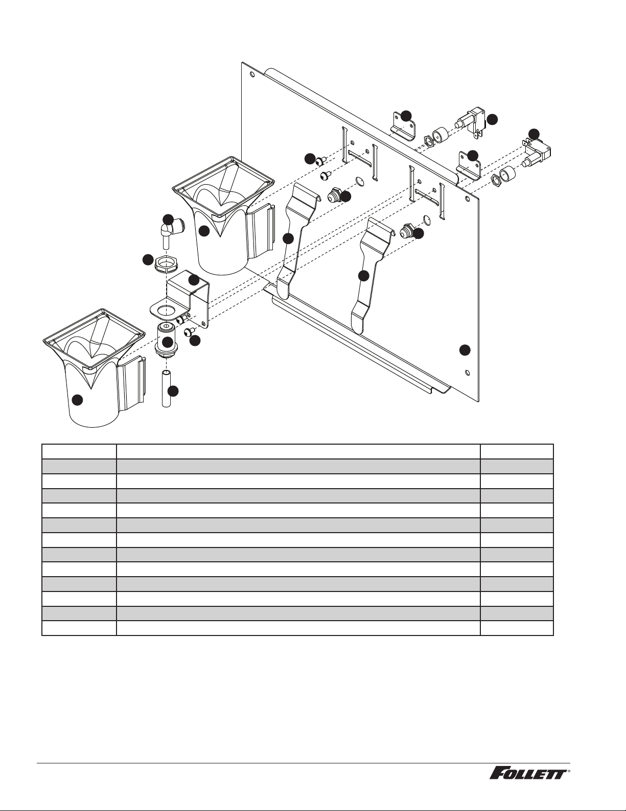
Dispense chute and splash panel (models with lever dispensing)
1
7
6
7
6
5
4
4
10
3
3
9
5
8
9
1
2
11
Reference # Description Part #
1 Chute, ice or water (with Agion
®
antimicrobial product protection
1
) 00967760
2 Support, water tube 00960682
3 Lever 00976845
4 Boot, dispense switch button 502418
5 Screw, panel 00982421
6 Switch, dispense 00981217
7 Bracket, lever support 00958793
8 Tube, water solenoid 502420
9 Fitting, bulkhead (with nut) 00976787
Not shown Splash panel (ice only) 01161256
10 Splash panel 00969980
11 Fitting, 1/4" stem x 1/4" push-in 00121699
1
Disclaimer: Antimicrobial protection is limited to the treated components and does not treat water or ice.
Agion is a registered trademark of Sciessent LLC.
44 12CI425A, 12HI425A
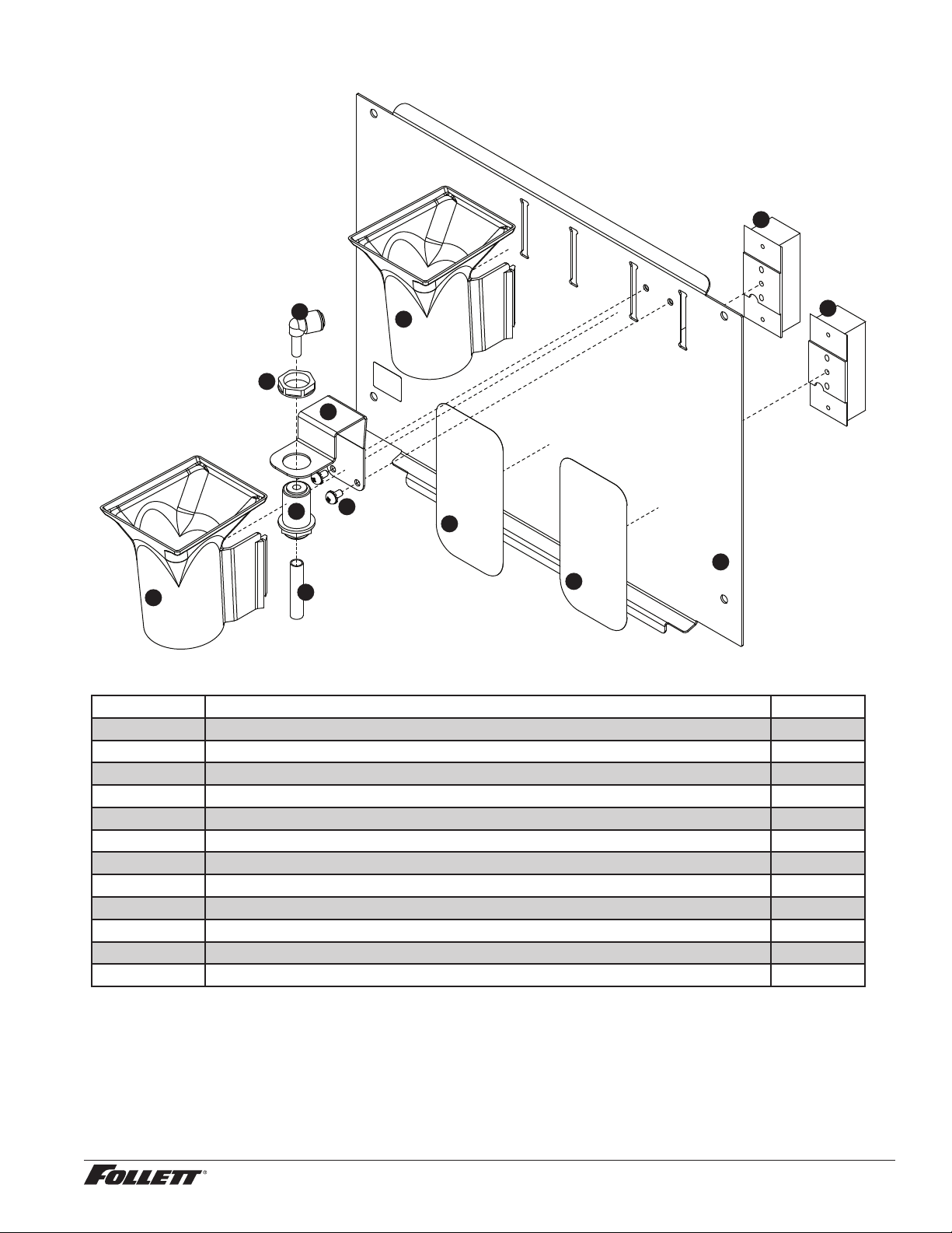
Dispense chute and splash panel (models with SensorSAFE infrared dispensing)
7
8
8
2
2
1
1
6
5
4
3
5
10
Reference # Description Part #
1 Chute, ice or water (with Agion) 00967760
2 Sensor (includes lens and Ty-rap*) 00122978
3 Support, water tube 00960682
4 Screw, panel 00982421
5 Fitting, bulkhead (with nut) 00976787
6 Tube, water solenoid 502420
Not shown Splash panel, without drain pan (includes 2 Ty-raps and 2 lenses) 00981357
7 Splash panel, (includes 2 Ty-raps and 2 lenses) 01161264
8 Lens, sensor (each) 502690
Not shown Splash panel, ice only (includes 1 Ty-raps and 1 lens) 01161272
9 Solenoid, assembly (includes ttings, screws) 00981209
10 Fitting, 1/4" stem x 1/4" push-in 00121699
* Ty-rap is a registered trademark of Thomas & Betts International, Inc.
12CI425A, 12HI425A 45
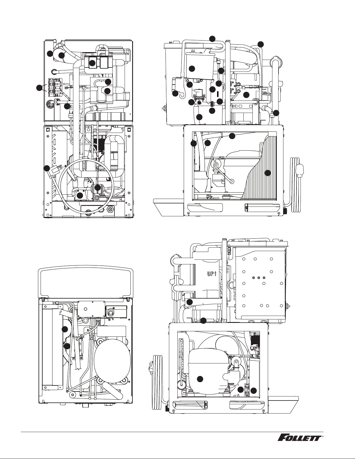
Ice machine components
5
17
12
7
20
23
14
3
3
22
13
8
26
19
28
24
3
25
27
2
25
Rear view Right side view
Left side viewTop view (lower section)
1
6
11
18
9
10
16
15
29
21
30
31
32
26
46 12CI425A, 12HI425A
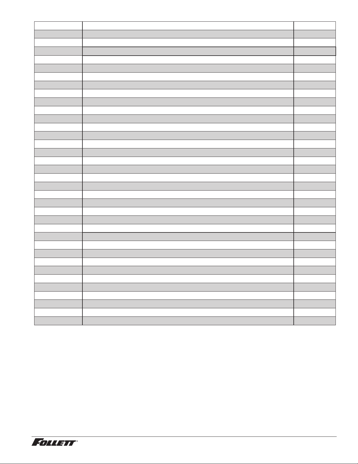
Reference # Description Part #
1 Drier 502724
2 Coil, condenser (includes shroud) 01065317
3
Reservoir (includes lid, gasket, fasteners, clean and vent tubing, cleaning cup) 01230622
Not shown Gasket, reservoir 00990978
4 Evaporator (see page 50 for detailed drawing) —
5 Drain pan, evaporator 502727
6 Valve, expansion, thermal 502726
7 Valve, shut-off, water, plastic, 1/4" 01035526
8 Gearbox & motor, 115 V, 60 Hz (includes 307192) 00142034
9 Fan blade 500474
10 Motor, fan, 115 V, 60 Hz 500672
11 Bracket, fan motor 01067107
Not shown Overload, compressor, 115 V, 60 Hz 01027572
12 Compressor, 115 V, 60 Hz 01065259
13 Tubing, polypropylene, reservoir supply (sold by the foot) 502079
14 Bracket, reservoir 01065408
15 Tube, ice transport 00168112
16 Insulation, ice tube, 12" (30.5 cm) required 501176
17 Bracket, gearmotor mounting 307192
18 Cord and plug, power 01035534
19 Hi-pressure cut-out 00117077
20 Clip, water shut-off valve 01035534
21 Tee, water, 1/4" 502923
Not shown Gasket, ice hose 00977322
22 Tubing, nozzle vent 01148691
23 Tubing, nozzle drain 01148790
24 Tubing, purge 01054790
25 Tubing, bin 01054782
26 Tube, ll/purge - reservoir-solenoid-evaporator feed (includes hose clamp) 01261536
27 Tubing, evaporator drain pan 01054154
28 Solenoid, purge 01261510
29 Solenoid, ll, dispense 01065283
30 Insulation, TEV 502830
31 Insulation, TEV bulb 00106534
32 Clamp, hose 01281450
12CI425A, 12HI425A 47
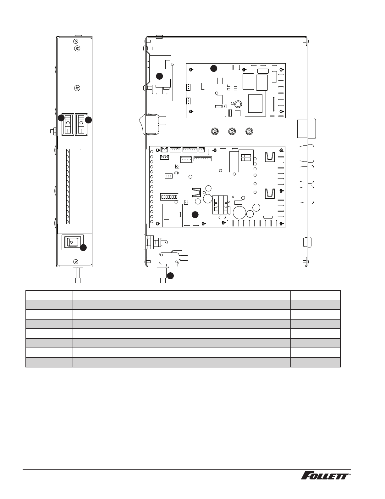
Electrical components
4
3
5
1
6
7
2
Reference # Description Part #
1 Board, control circuit, 115 V, 60 Hz 01064708
2 Switch, clean 01229418
3 Switch, rocker, power 502209
4 Switch, rocker, bin signal 502209
5 Switch, cleaning, SensorSAFE models 502409
6 Control board, SensorSAFE models 502242
7 Bin thermostat 500514
48 12CI425A, 12HI425A
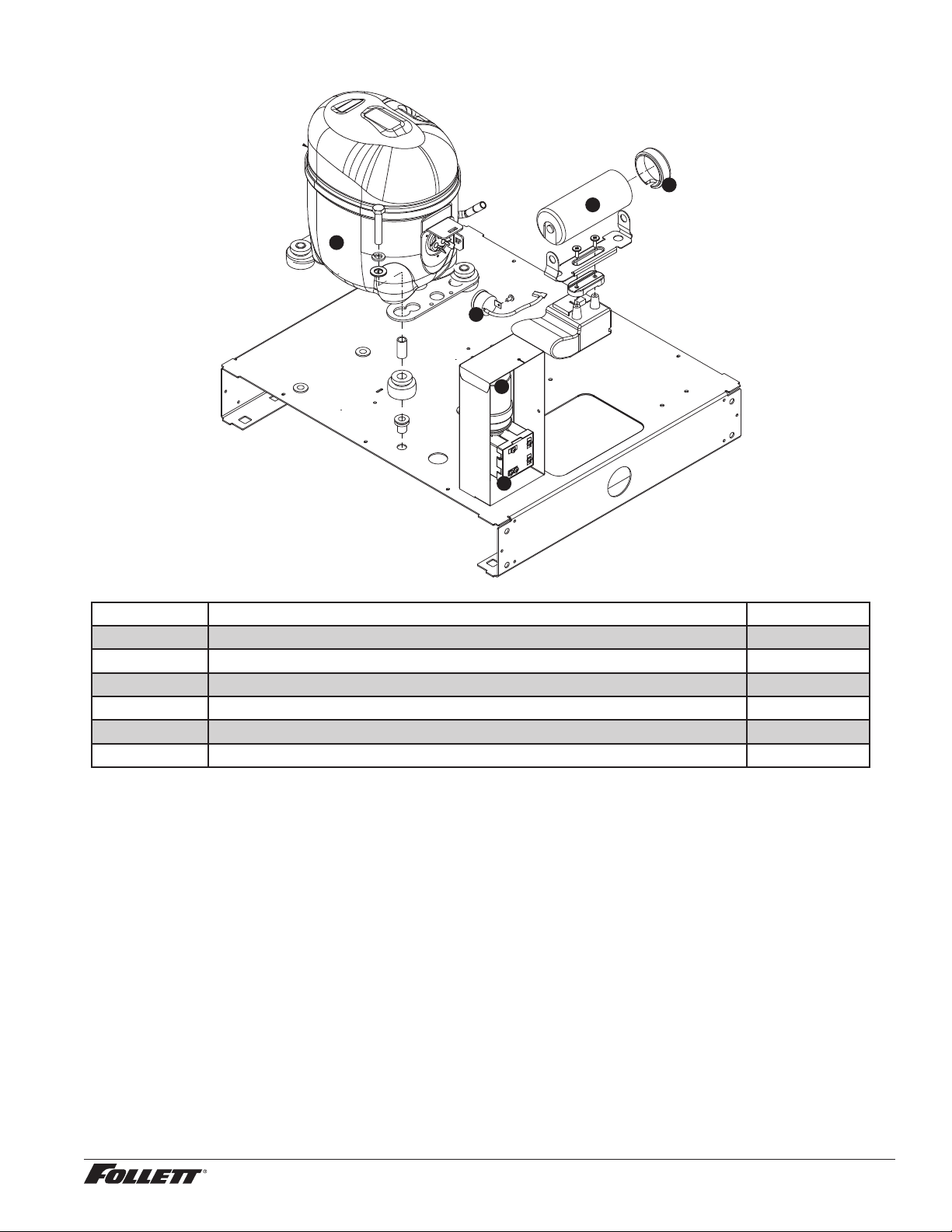
Compressor
1
2
4
3
5
6
Reference # Description Part #
1 Compressor, 120 V (includes start cap, run cap, and start relay) 01065259
2 Capacitor, start 01026145
3 Cap, end 01027556
4 Overload, compressor 01027572
5 Capacitor, run 00997759
6 Relay, start 00997726
12CI425A, 12HI425A 49
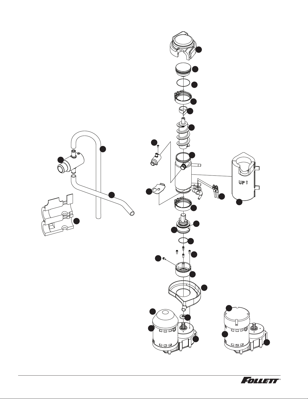
Evaporator replacement parts
HEALTHCARE
15
17
18
24
1
3
4
5
20
19
7
6
8
10
11
12
16
9
22
21
13
1
23
2
25
26
13
27
28
29
50 12CI425A, 12HI425A
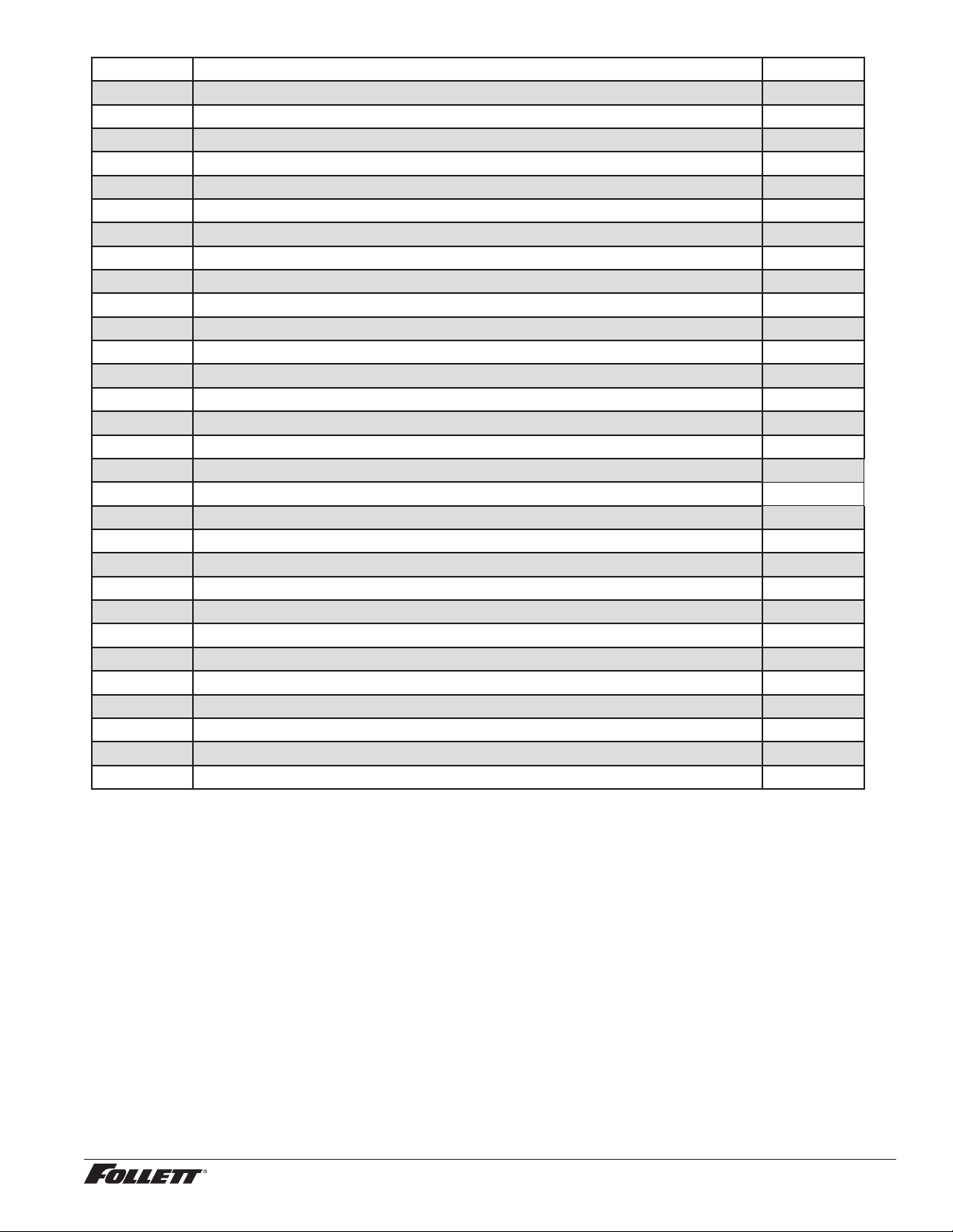
Reference # Description Part #
1 Coupling, vee band, includes nut 502735
2 Bearing assembly, top 502736
3 Loop, ice compression, beveled 502110
4 Auger (see below for Flaker-specic components) 502737
5 Evaporator (includes insulation jacket, and top bearing insulation) 01064658
6 Bearing assembly, bottom (includes O rings and condensate shield) 502738
7 O ring, bearing housing 500496
8 O ring, mounting base 501063
9 Shield, condensate 500744
10 Screw, Allen 1/4 20 x 1/2 (set of 4) 501080
11 Mounting base, evap. (includes 501063) 502733
12 Bolt, mounting base 502227
13 Gearbox & motor (includes mounting base) 00142034
Not shown Mounting base, gearbox 01067693
15 Compression nozzle, with single drain 01064674
16 Drain pan, evaporator 502727
17 Tube, compression nozzle vent
01148691
18 Tube, compression nozzle, single drain
01148790
Not shown Grease, Mobil FM222, 14 oz 501111
19 Bracket, vent hoses 01007087
20 Insulation jacket, evaporator 01049592
21 Relay, gearmotor 00142042
22 Cover, black plastic 01012228
23 O ring, top bearing 01064963
24 Insulation, top bearing 01049600
25 Insulation, compression nozzle, single drain 01049584
26 16 µF Capacitor (for PSC motor only) 01103142
27 Screw, compression nozzle 00956250
28 Cover, aluminum 01106376
Not shown O-ring, compression nozzle 00988097
12CI425A, 12HI425A 51
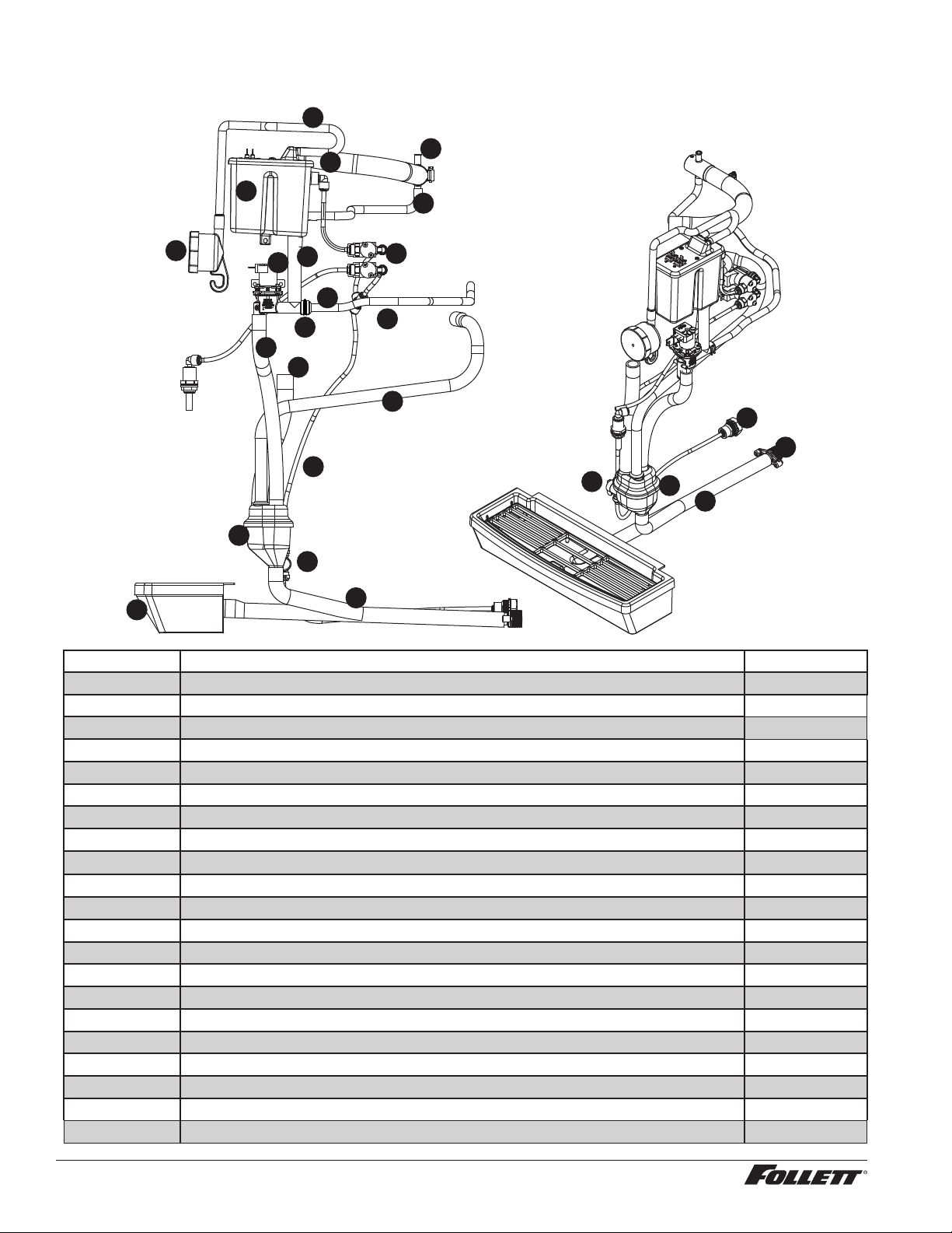
Water supply and drains
9
9
2
3
12
9
11
8
4
5
10
6
13
14
1
19
18
7
18
17
16
15
1
20
6
Reference # Description Part #
1 Cup, drain 01064690
2 Tube, nozzle vent 01148691
3 Tube, nozzle drain 01148790
4 Tube, purge 01054790
5 Tube, bin 01054782
6 Tube, ll/purge - reservoir-solenoid-evaporator feed (includes hose clamp) 01261536
7 Tube, evaporator drain pan 01054154
8 Solenoid, purge 01261510
9
Reservoir (includes lid, gasket, fasteners, clean and vent tubing, cleaning cup) 01230622
10 Tee, water, 1/4" 502923
11 Solenoid, ll, dispense 01065283
12 Fitting, 1/4" stem x 1/4" push-in 00121699
13 Tubing, 1/4" 502079
14 Clip, 1/4" valve 01035534
15 Valve, 1/4" 01035526
16 Fitting, 3/8" FPT x 1/4" push-in 01065275
17 Fitting, 3/4" MPT x 3/4" barb 00109728
18 Tube, drain pan/collector cup 01065390
19 Drain pan 00967059
Not shown Bracket, drain cup 01051945
20 Clamp, hose 01281450
52 12CI425A, 12HI425A
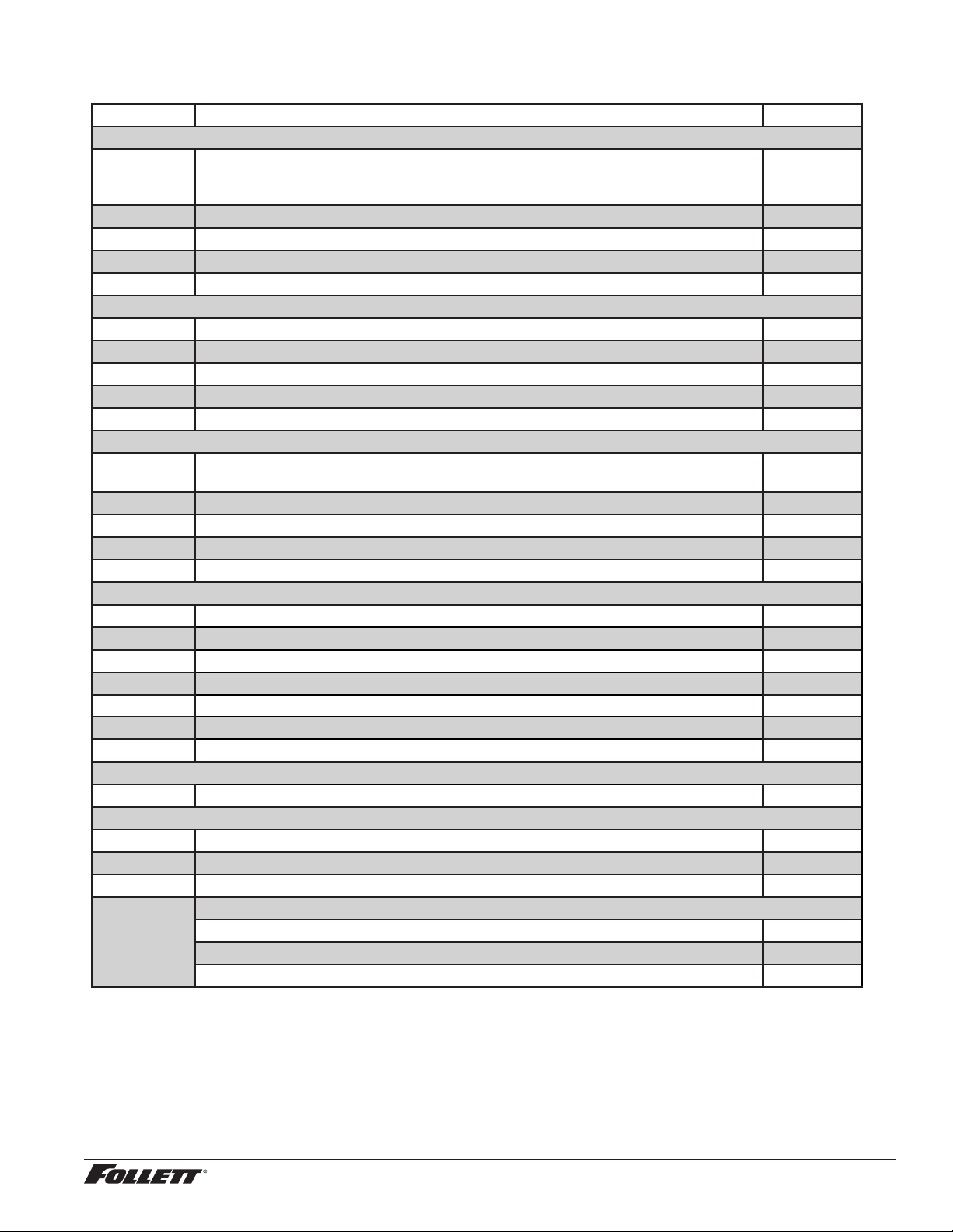
Water treatment accessories for Symphony Plus ice and water dispensers
Reference # Description Part #
Standard capacity lter system
Not shown Follett QC4-FL4S water lter system (includes FL4S primary cartridge and head, coarse
pre-lter and head, pressure gauge, ushing valve; assembled and installed on mounting
bracket), one per ice machine
00130229
Not shown Follett FL4S primary replacement cartridge 00130245
Not shown Water lter cartridge – primary, carton of 6 00954297
Not shown Everpure coarse pre-lter cartridge 00130211
Not shown Water pre-lter cartridge – pre-lter, carton of 12 00954305
High capacity lter system
Not shown High capacity water lter system (one per ice machine) 00978957
Not shown High capacity water lter cartridge – primary, single 00978965
Not shown High capacity water lter cartridge – primary, carton of 6 00978973
Not shown Water pre-lter cartridge – pre-lter, single 00130211
Not shown Water pre-lter cartridge – pre-lter, carton of 12 00954305
Carbonless high capacity lter system
Not shown Carbonless high capacity water lter system (one per ice machine) – Horizon™ and
MaestroPlus series ice machines
01050442
Not shown Carbonless high capacity water lter cartridge – primary, single 01050426
Not shown Carbonless high capacity water lter cartridge – primary, carton of 6 01050434
Not shown Water pre-lter cartridge – pre-lter, single 00130211
Not shown Water pre-lter cartridge – pre-lter, carton of 12 00954305
Other ltration
Not shown Claris hardness removal ltration system 00986059
Not shown Replacement lter for Claris system 00985127
Not shown Reverse osmosis system, 200 gallons per day 00986034
Not shown Replacement reverse osmosis cartridge 00985085
Not shown Replacement reverse osmosis pre-lter 00985077
Not shown Cleaning plug for reverse osmosis system 00985119
Not shown Cleaning cartridge for reverse osmosis system 00985101
Water pressure
Not shown Water pressure regulator (25 psi) 501781
Cleaning/Sanitizing
Not shown SafeCLEAN Plus, case of 6 01149954
Not shown SafeCLEAN Plus, case of 24 011499 62
Not shown Sponge, sanitary, each 00131524
Not shown IMS-III sanitizing concentrate
16 oz bottle 00979674
Case of 12 x 16 oz bottles 01038652
Sponge, sanitary, pack of 24 01075431
12CI425A, 12HI425A 53

54 12CI425A, 12HI425A
Warranty Registration and Equipment Evaluation
Thank you for purchasing Follett ® equipment. Our goal is to deliver high value products and services that earn your complete
satisfaction by delivering high-value products and services backed by outstanding customer and technical support.
Please review the installation instructions thoroughly. It is important that the installation be performed to factory specications so
your equipment operates at its maximum efficiency.
Follett LLC will not be liable for any consequential damages, expenses, connecting or disconnecting charges, or any losses
resulting from a defect of the machine. For full warranty details, visit our website www.follettice.com/productwarranties.
Registering your equipments helps Follett track your equipment's service history should you need to contact us for technical
support, and your feedback helps us improve our products and services. Please visit www.follettice.com/support to complete the
Warranty Registration form.
Should you have any questions, please contact Follett's technical support group at (877) 612-5086 or (610) 252-7301 and we will
be happy to assist you.

12CI425A, 12HI425A 55

01234608R06
© Follett LLC 3/20
801 Church Lane • Easton, PA 18040, USA
Toll free (877) 612-5086 • +1 (610) 252-7301
www.follettice.com
Calgon is a licensed trademark distributed by Nu-Calgon, in the United States.
Dow Corning is a registered trademark of Dow Corning Corporation in the United States and other countries.
SafeCLEAN, SaniSponge, SensorSAFE, and Symphony Plus are trademarks of Follett LLC.
Follett is a registered trademarks of Follett LLC, registered in US.