
NZ AU GB IE
590477A 02.13
OB60SL models
INSTALLATION INSTRUCTIONS
Built-in Oven
2
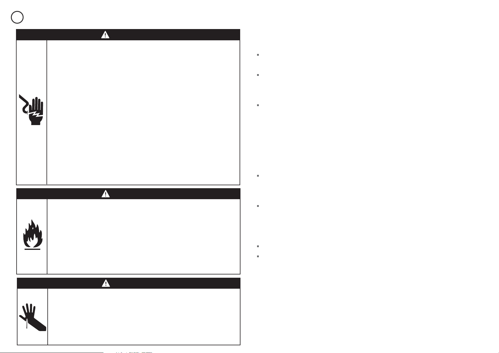
WARNING!
Electrical shock hazard
Before carrying out any work on the
electrical section of the appliance, it must
be disconnected from the mains electricity
supply.
Connection to a good earth wiring system
is absolutely essential and
mandatory.
Alterations to the domestic wiring
system must only be made by a qualified
electrician.
Failure to follow this advice may result in
electrical shock or death.
WARNING!
Cut hazard
Take care - some panel edges are sharp.
Failure to use caution could result in injury
or cuts.
SAFETY AND WARNINGS
1
WARNING!
Fire hazard
Do not use adapters, reducers, or
branching devices to connect this
appliance to the mains power supply.
Failure to follow this advice may result in
overheating, burning, or fire.
IMPORTANT SAFETY INSTRUCTIONS!
To avoid hazard, follow these instructions carefully
before installing or using this appliance.
Please make this information available to the person
installing the appliance - doing so could reduce your
installation costs.
This appliance must be installed and connected to
the mains power supply only by a suitably qualified
person according to these installation instructions
and in compliance with any applicable local building
and electricity regulations. Failure to install the
appliance correctly could invalidate any warranty or
liability claims.
If the power supply cable is damaged, it must be
replaced by the manufacturer, its service agent or
similarly qualified person in order to avoid a hazard.
Isolating switch: make sure this oven is connected
to a circuit which incorporates an isolating switch
providing full disconnection from the power supply
in accordance with the wiring rules.
The oven must be earthed.
Do not use adaptors, reducers or branching devices
to connect the oven to the mains electricity supply,
as they can cause overheating and burning.

3
PRIOR TO INSTALLATION
AFTER INSTALLATION
2
3
the benchtop and oven cavity are square and level, and are the required dimensions.
the installation will comply with all clearance requirements and applicable standards and regulations.
a suitable isolating switch providing full disconnection from the mains power supply is incorporated in the permanent wiring, mounted and positioned to comply with the local wiring rules and regulations. The
isolating switch must be of an approved type and provide a 3 mm air gap contact separation in all poles (or in all active [phase] conductors if the local wiring rules allow for this variation of the requirements).
the isolating switch will be easily accessible to the customer with the oven installed.
there is at least 1.5 m (and not more than 2 m) free length of power supply cable within the cavity for ease of installation and servicing.
the oven connection socket (if fitted) is outside the cavity if the oven is flush to the rear wall.
the oven will rest on a surface that can support its weight.
the height from the floor suits the customer.
you consult local building authorities and by-laws if in doubt regarding installation.
Important!
Some environmental factors and cooking habits can cause condensation in and around the oven during use. To protect surrounding cabinetry from possible damage caused by frequent or excessive condensation, we recommend
moisture-proofing the oven cavity.
Important!
Please take extra care not to damage the lower trim of the oven during installation. The trim is important for correct air circulation and allows the door to open and close without obstruction. The manufacturer does not accept any
responsibility for damage resulting from incorrect installation.
the oven door can open fully without obstruction.
the power supply cable does not touch any hot metal parts.
the isolating switch is easily accessible to the customer with the oven installed.
you complete the ‘Final checklist’ at the end of the installation.
If, after following the instructions given, correct performance cannot be achieved, please contact your nearest Fisher & Paykel Authorised Service Centre, Customer Care, or contact us through our local website listed at
the end of this document.
PARTS SUPPLIED
4
Screws (2)
4
5
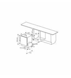
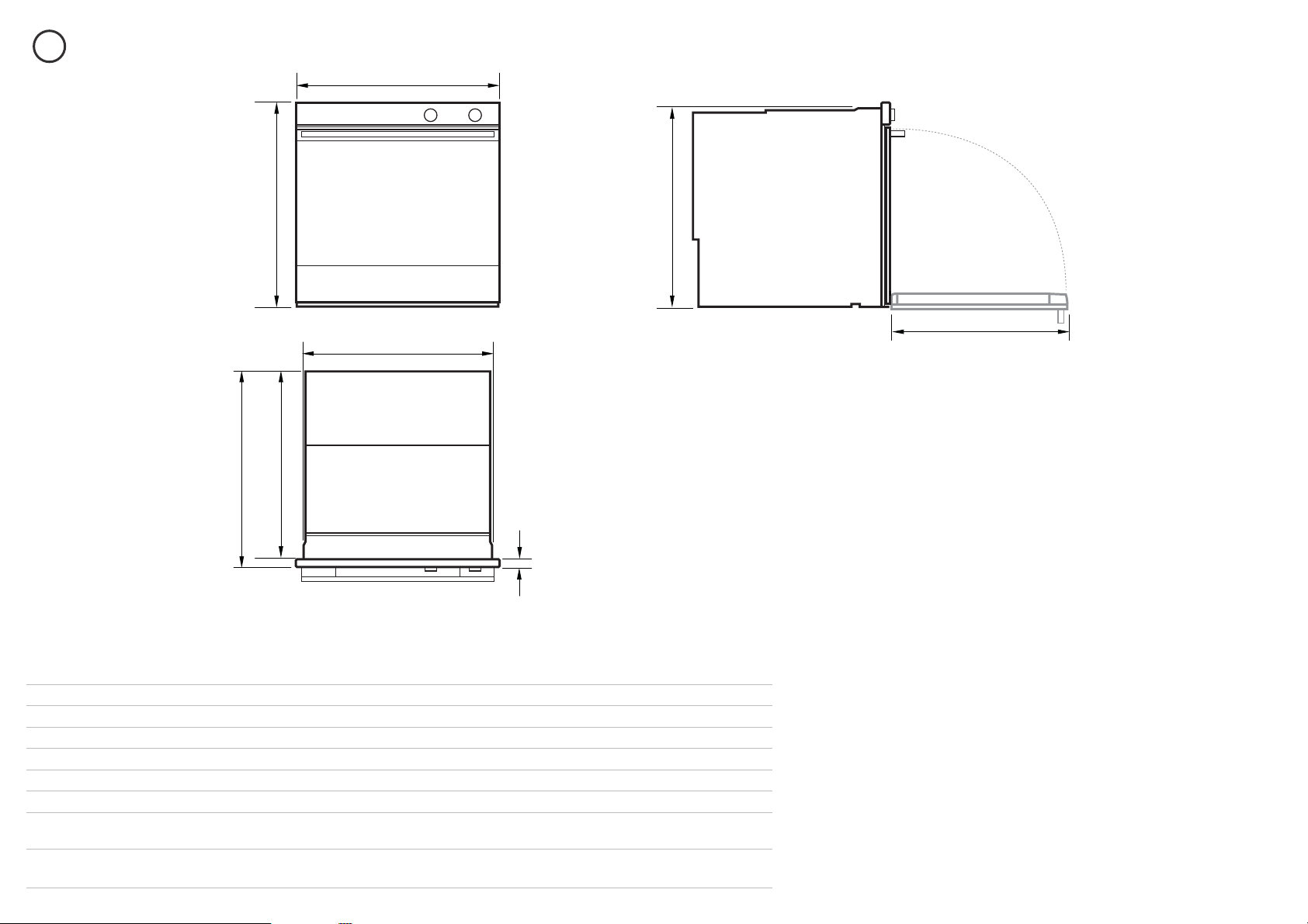
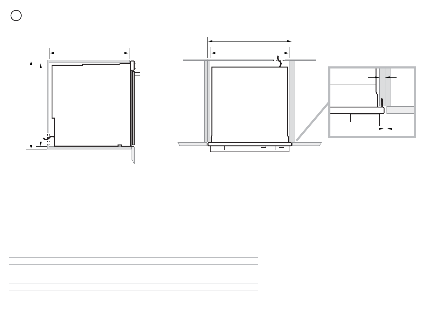
PRODUCT DIMENSIONS
Product dimensions (mm)
OB60SL7
OB60SL9
OB60SL11
A
overall height of product 598 598 598
B
overall width of product 597 597 597
C
overall depth of product (excluding handle and dials) 577 577 577
D
height of chassis 578 578 578
E
width of chassis 556 556 556
F
depth of chassis 557 557 557
G
depth of oven frame and control panel
(=distance between front of chassis and front of oven door, excl. knobs)
20 20 20
H
depth of oven door when fully open
(measured from front of control panel)
493 493 493
A
CF
B
E
G
H
D
TOP
FRONT SIDE
5
5
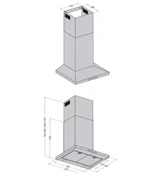
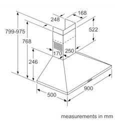
CABINETRY DIMENSIONS
Cabinetry dimensions (mm)
OB60SL7
OB60SL9
OB60SL11
I
minimum inside width of cavity 560 560 560
J
overall width of cabinetry 600 600 600
K
minimum inside height of cavity 580 580 580
L
overall height of cabinetry 600 600 600
M
minimum inside depth of cavity 560 560 560
Note: If installing a cooktop above the oven, ensure adequate clearance is provided for the cooktop as per the cooktop manufacturer’s
instructions.
I
J
K
L
M
16-20 mm
Electrical supply
min. 1.5 mm
TOP
SIDE
6
6
7
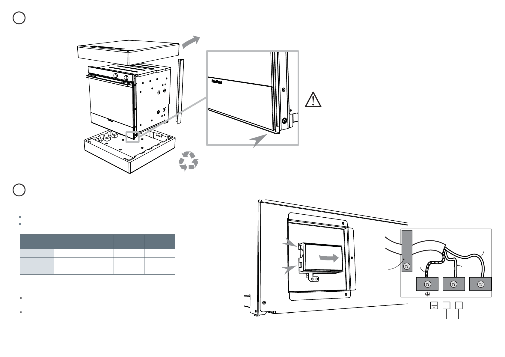
DISCARD PACKAGING RESPONSIBLY
CONNECT THE OVEN TO THE MAINS SUPPLY
Unclip
and lift up
L1N(L2)E
Brown
(Live)
Ensure cable
clamp is
tightened
with screw
(you may have
to remove the
screw rst before
tting the clamp)
L
N
Green
& Yellow
(Earth)
Blue
(Neutral)
Recycle responsibly
lower trim
Important!
When you remove the oven from the carton be
careful not to damage the lower trim. The trim is
important for both ventilation and to ensure the
door opens fully without obstruction.
Important!
This oven must be connected to the mains power supply only by a suitably qualified person.
This oven must be earthed.
Model code Max Power
(W)
Hz Voltage (V) Amps (A)
OB60SL7
3000 50 Hz 220 - 240 V~ 14
OB60SL9
3600 50 Hz 220 - 240 V~ 16
OB60SL11
3600 50 Hz 220 - 240 V~ 16
Before connecting the oven to the mains power supply, check that:
the domestic wiring system is suitable for the power drawn by the oven
(as speci ed on the rating plate)
the voltage corresponds to the value given on the rating plate.
7
8
9
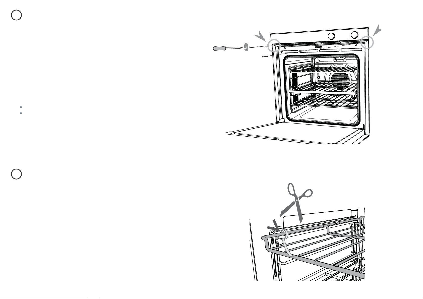
SECURE THE OVEN TO THE CABINETRY
REMOVE ALL CABLE TIES & PACKAGING HOLDING THE SHELVING IN PLACE
1
Position the oven in the prepared cavity.
Important!
Do not lift the oven by the door handle.
2
Open the oven door fully.
3
Use the supplied screws to secure the oven to the cabinetry.
Important!
Do not over-tighten the screws.
Do not seal the oven into the cabinetry with silicone or glue. This makes future
servicing difficult. Fisher & Paykel will not cover the costs of removing the oven,
or of damage caused by this removal.
Important!
Make sure you remove all the cable ties and
any internal packaging holding the shelving
in place. The cable ties, if left in the oven
during operation, may result in damage to the
oven.

10
FINAL CHECKLIST
Important!
SAVE THESE INSTRUCTIONS
The models shown in this document may not be available in all markets and are subject to change
at any time. For current details about model and specification availability in your country, please
visit our website listed at the end of this document or contact your local Fisher & Paykel dealer.
www. sherpaykel.com
TO BE COMPLETED BY THE INSTALLER
Make sure the oven is level and securely fitted to the cabinetry.
Check the lower trim is undamaged.
Open the oven door slowly until it is fully open and check there is adequate
clearance between the bottom of the door and the lower trim. This is to
ensure correct air circulation. Should the lower trim become damaged,
straighten the trim and ensure the oven door opens fully without
obstruction.
Make sure all cable ties and internal packaging has been removed from the
oven cavity.
Make sure all oven vents and openings are clear and free of any
obstruction or damage.
Important!
Failure to make sure all oven vents are clear may result in poor product
performance.
Make sure the isolating switch is accessible by the customer.
TEST OPERATION:
Turn the power to the oven on. The display should light up and show
0:00. Set the clock following the instructions in the ‘Quickstart Guide’ or
‘User guide’.
Turn the oven function to ‘Bake’. Inside the oven cavity, the oven light should
come on. Air should blow out of the vent at the top of the oven.
Have you demonstrated the basic operation to the customer?
Turn the temperature to 50
o
C. The temperature indicator should come on.
After five minutes, open the oven door: the air inside should feel warm.
Turn the oven function dial back to OFF.
Installer’s name:
Installer’s signature:
Installation company:
Date of installation:
LEAVE THESE INSTRUCTIONS WITH THE CUSTOMER