Loading ...
Loading ...

Page 3 of 6
ASSEMBLY INSTRUCTIONS (continued)
1.
Thread two headless screws (DD)
through the cross bar (AA), and then
secure them with four lock nuts (FF)
(two on each side of the cross bar(AA)).
Adjust the length of the headless
screws (DD) if necessary.
Note: Make sure that the headless
screws (DD) are lined up horizontally
to make the fixture level.
AA
DD
FF
AA
BB
1
2
3
2. Attach cross bar (AA) to outlet box
using two mounting screws (BB).
3. Pull out the source wires from the
outlet box. Make wire connections
using wire connectors as follows:
•Connect the hot wire (usually black
insulation) from the fixture to the black
wire from the power source.
•Connect the neutral wire (usually
white insulation) from the fixture
to the white wire from the power
source.
•Attach the fixture grounding
wire (usually green insulation or
bare wire) to the cross bar (AA) with
the green grounding screw, and
then connect it to the house
grounding wire with the wire connector (CC).
Carefully put all of the wires back
into the outlet box.
AA
CC
4. Attach the fixture to the cross
bar (AA) by inserting headless
screws (DD) into holes on back
plate (A), and then secure it with
two rubber pads (GG) and two
ball nuts (EE).
CAUTION:With silicone
caulking compound, caulk
completely around where the
back plate meets with the
wall surface to prevent water
from seeping into the outlet
box.
5. Install a bulb (not included).
Check relamping label at socket
area or packaging for maximum
allowed wattage.
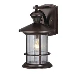
The Position of Adjustable Knob
Sensor
Lens
Adjustable
Knob
See Detail A
Fig.1
Fig.2
Fig.3
4
5
DD
A
GG
EE
AA
DD
Bulb type
A Max. 60W
(not include)
Socket
Loading ...
Loading ...
Loading ...