Loading ...
Loading ...
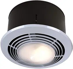
MODEL 9093WH
Page 3
HEATER
JUNCTION
BOX
YELLOW
BLUE
BLACK
RED
HOUSE
WIRING
SWITCH BOX
(REAR VIEW)
HOUSE
WIRING
120vAC
LINE
TO HOUSE
PANEL BOARD
BLACK
WHITE
GROUND
VENT
LIGHT
HEAT
NIGHT
LIGHT
T
WHITE
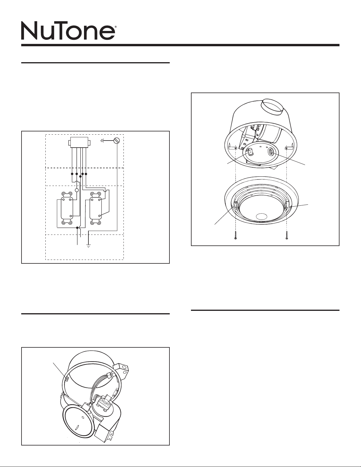
FIGURE 2
WIRING
Installation work and electrical wiring must be done by
a qualified person(s) in accordance with all applicable
codes and standards, including fire-rated construction
codes and standards.
Refer to Figure 2.
1. Run five (5) wires and ground of 12 gauge from heater’s
junction box to wall switch.
2. The switch installs in a double-gang outlet box. When a
thermostat or timer is used, connect at point marked “T”.
3. Replace junction box cover in heater housing when wiring
is complete.
COMPLETING INSTALLATION
Refer to Figure 3.
1. Insert hooked hinge on power unit to hanger bracket in
rough-in housing.
2. Swing fan and heater unit into place over mounting bracket
screws and tighten securely.
3. Plug in fan and heater assembly to receptacle in junction
box cover.
Refer to Figure 4.
4. Install 100 watt bulb and 7 watt lamp for night light.
5. Mount grille and lens assembly over mounting screws in
housing. Tighten securely.
INSTALLATING IN EXISTING
CONSTRUCTION
1. Review “WIRING” section of these instructions.
2. Drill a small hole in ceiling in proposed location (locate
this hole in attic or crawl space).
3. In attic, mark ceiling for cutout by using the housing as
a template. Mark around outside of plaster flange. Make
cutout along this line.
4. Connect wires from switch to heater before mounting
the housing.
5. Install a header between ceiling joists and nail housing to
one joist and header.
NOTE: The two (2) hanger bars (separate pieces) and two
mounting brackets (on the housing) are not needed for this
type of installation.
6. Install ductwork.
7. Install power unit, light bulbs and grille/lens assembly. Refer
to “COMPLETING INSTALLATION”.
NOTE: Please refer to your NuTone catalog for a complete
listing of optional accessory items.
FIGURE 3
SLOTTED
HANGER BRACKET
FIGURE 4
LIGHT
RECEPTACLE
NIGHT LIGHT
RECEPTACLE
KEY-HOLE
SLOT
KEY-HOLE
SLOT
Loading ...
Loading ...
Loading ...