
Operator's Manual
2-Cycle
WEEDWACKER® GAS TRIMMER
Model No. 316.791860
U_U_VASLE STA#T/N0 EA SE _
* SAFETY
* ASSEMBLY
* OPERATION
* MAINTENANCE
* PARTS LIST
* ESPANOL, R 11
CAUTION: Before using this
product, read this manual and
follow all safety rules and
operating instructions.
Sears, Roebuck and Co., Hoffman Estates, IL 60179, U.S.A.
Visit our website: www.sears.corn/craftsrnan
769-04884 P01 5/09
CALiFORNiA PROPOSiTiON 65 WARNING
THE ENGINE EXHAUST FROM THIS PRODUCT CONTAINS
CHEMICALS KNOWN TO THE STATE OF CALiFORNiA TO CAUSE
CANCER, BIRTH DEFECTS OR OTHER REPRODUCTIVE HARM.
TABLE OF CONTENTS
Safety Rules .......................................... 2
Warranty ............................................. 4
Know Your Unit ........................................ 4
Assembly instructions ................................... 4
Oil and Fuel information ................................. 5
Starting/Stopping instructions ............................ 5
Operating instructions ................................... 6
Maintenance and Repair instructions ....................... 6
Cleaning and Storage ................................... 8
Troubleshooting Chart ................................... 9
Specifications ........................................ 10
Parts List ............................................ 22
Service Numbers .............................. Back Cover
SPARK ARRESTOR NOTE
NOTE: For users on U.S. Forest Land and in the states of California,
Maine, Oregon and Washington. All U.S. Forest Land and the state of
California (Public Resources Codes 4442 and 4443), Oregon and
Washington require, by law that certain internal combustion engines
operated on forest brush and/or grass-covered areas be equipped with a
spark arrestor, maintained in effective working order, or the engine be
constructed, equipped and maintained for the prevention of fire. Check
with your state or local authorities for regulations pertaining to these
requirements. Failure to follow these requirements could subject you to
liability or a fine. This unit is factory equipped with a spark arrestor, if
it requires replacement, ask your LOCAL SERVICE DEALER to install the
Accessory Part #753-05169 Muffler Assembly
All information, illustrations, and specifications in this manual are based
on the latest product information available at the time of printing. We
reserve the right to make changes at any time without notice.
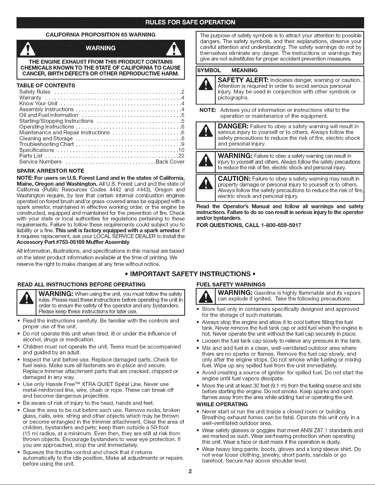
The purpose of safety symbols is to attract your attention to possible I
dangers. The safety symbols, and their explanations, deserve your I
careful attention and understanding. The safety warnings do not by I
themselves eliminate any danger. The instructions or warnings they I
give are not substitutes for proper accident prevention measures.
SYMBOL MEANING
SAFETY ALERT: indicates danger, warning or caution.
Attention is required in order to avoid serious personal
injury. May be used in conjunction with other symbols or
pictographs.
NOTE: Advises you of information or instructions vital to the
operation or maintenance of the equipment.
_ ANGER: Failure to obey a safety warning will result in
serious injury to yourself or to others. Always follow the
safety precautions to reduce the risk of fire, electric shock
and personal injury.
WARNING: Failureto obey a safety warning can result ininjury to yourself and others. Always follow the safety precautions
to reduce the risk of fire, electric shock and personal injury.
CAUTION: Failure to obey a safety warning may result in
property damage or personal injury to yourself or to others.
Always follow the safety precautions to reduce the risk of fire
electric shock and personal injury.
Read the Operator's Manual and follow all warnings and safety
instructions. Failure to do so can result in serious injuryto the operator
and/or bystanders.
FOR QUESTIONS, CALL 1-800-659-5917
= IMPORTANT SAFETY INSTRUCTIONS =
READ ALL INSTRUCTIONS BEFORE OPERATING
_ ARNING: When using the unit, you must follow the safety
rules. Please read these instructions before operating the unit in
order to ensure the safety of the operator and any bystanders.
Please keep these instructions for later use.
• Read the instructions carefully. Be familiar with the controls and
proper use of the unit.
Do not operate this unit when tired, ill or under the influence of
alcohol, drugs or medication.
Children must not operate the unit. Teens must be accompanied
and guided by an adult.
inspect the unit before use. Replace damaged parts. Check for
fuel leaks. Make sure all fasteners are in place and secure.
Replace trimmer attachment parts that are cracked, chipped or
damaged in any way.
Use only Hassle FreeTM XTRA QUIET Spiral Line. Never use
metal-reinforced line, wire, chain or rope. These can break off
and become dangerous projectiles.
Be aware of risk of injury to the head, hands and feet.
Clear the area to be cut before each use. Remove rocks, broken
glass, nails, wire, string and other objects which may be thrown
or become entangled in the trimmer attachment. Clear the area of
children, bystanders and pets; keep them outside a 50-foot
(15 m) radius, at a minimum. Even then, they are still at risk from
thrown objects. Encourage bystanders to wear eye protection, if
you are approached, stop the unit immediately.
Squeeze the throttle control and check that it returns
automatically to the idle position. Make all adjustments or repairs
before using the unit.
FUEL SAFETY WARNINGS
[_ ARNING: Gasoline is highly flammable and its vaporscan explode if ignited. Take the following precautions:
Store fuel only in containers specifically designed and approved
for the storage of such materials.
Always stop the engine and allow it to cool before filling the fuel
tank. Never remove the fuel tank cap or add fuel when the engine is
hot. Never operate the unit without the fuel cap securely in place.
Loosen the fuel tank cap slowly to relieve any pressure in the tank.
Mix and add fuel in a clean, well-ventilated outdoor area where
there are no sparks or flames. Remove the fuel cap slowly, and
only after the engine stops. Do not smoke while fueling or mixing
fuel. Wipe up any spilled fuel from the unit immediately.
Avoid creating a source of ignition for spilled fuel. Do not start the
engine until fuel vapors dissipate.
Move the unit at least 30 feet (9.1 m) from the fueling source and site
before starting the engine. Do not smoke. Keep sparks and open
flames away from the area while adding fuel or operating the unit.
WHILE OPERATING
= Never start or run the unit inside a closed room or building.
Breathing exhaust fumes can be fatal. Operate this unit only in a
well-ventilated outdoor area.
Wear safety glasses or goggles that meet ANSi Z87.1 standards and
are marked as such. Wear ear/hearing protection when operating
this unit. Wear a face or dust mask if the operation is dusty.
Wear heavy long pants, boots, gloves and a long sleeve shirt. Do
not wear loose clothing, jewelry, short pants, sandals or go
barefoot. Secure hair above shoulder level.
• Thetrimmerattachmentshieldmustalwaysbeinplacewhile • Turntheenginetooffanddisconnectthesparkplugfor
operatingtheunit.Donotoperateunitwithoutbothtrimminglines
extended,andtheproperlineinstalled.Donotextendthe
trimminglinebeyondthelengthoftheshield.
Thisunithasa clutch.Thetrimmerattachmentremainsstationary
whentheengineisidling.If itdoesnot,taketheunittoaSearsor
otherqualifiedservicedealerforanadjustment.
AdjusttheD-handletoyoursizeinordertoprovidethebestgrip.
Besurethetrimmerattachmentisnotincontactwithanything
beforestartingtheunit.
Usetheunitonlyindaylightorgoodartificiallight.
Avoidaccidentalstarting.Beinthestartingpositionwhenever
pullingthestarterrope.Theoperatorandunitmustbeinastable
positionwhilestarting.RefertoStarting/StoppingInstructions.
Usetherighttool.Onlyusethistoolforitsintendedpurpose.
Alwaysholdtheunitwithbothhandswhenoperating.Keepafirm
griponbothhandlesorgrips.
Keephands,face,andfeetawayfromallmovingparts.Donot
touchortrytostopthetrimmerattachmentwhenitrotates.
Donottouchtheengine,gearhousingormuffler.Thesepartsget
extremelyhotfromoperation,evenaftertheunitisturnedoff.
Donotoperatetheenginefasterthanthespeedneededtocut,trim
oredge.Donotruntheengineathighspeedwhennotcutting.
Alwaysstoptheenginewhencuttingisdelayedorwhenwalking
fromonecuttinglocationtoanother.
Ifyoustrikeorbecomeentangledwithaforeignobject,stoptheengine
immediatelyandcheckfordamage.Donotoperatebeforerepairing
damage.Donotoperatetheunitwithlooseordamagedparts.
maintenanceorrepair.
Useonlyreplacementpartsoraccessoriesrecommendedforthis
toolthataredistributedbySearsoraCraftsmanoutlet.Useof
anyreplacementpartsoraccessoriespurchasedelsewheremay
behazardous,andwillalsovoidyourwarranty.
Keepunitcleanofvegetationandothermaterials.Theymay
becomelodgedbetweenthetrimmerattachmentandshield.
Toreducefirehazard,replaceafaultymufflerandsparkarrestor.
Keeptheengineandmufflerfreefromgrass,leaves,excessive
greaseorcarbonbuildup.
OTHERSAFETYWARNINGS
Neverstoretheunitwithfuelinthetank,insidea buildingwhere
fumesmayreachanopenflame(pilotlights,etc.)orsparks
(switches,electricalmotors,etc.).
Allowtheenginetocoolbeforestoringortransporting.Besureto
securetheunitwhiletransporting.
Storetheunitinadryplace,securedorataheighttoprevent
unauthorizeduseordamage.Keepoutofthereachofchildren.
Neverdouseorsquirttheunitwithwateroranyotherliquid.Keep
handlesdry,cleanandfreefromdebris.Cleanaftereachuse,see
CleaningandStorageinstructions.
Keeptheseinstructions.Refertothemoftenandusethemto
instructotherusers.Ifyouloanthisunittoothers,alsoloanthem
theseinstructions.
SAVETHESE INSTRUCTIONS
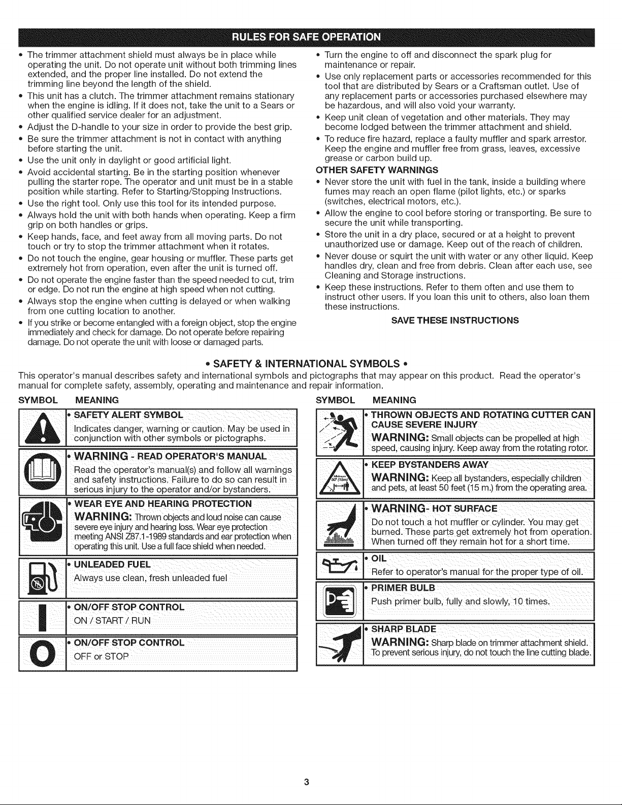
• SAFETY & INTERNATIONAL SYMBOLS •
This operator's manual describes safety and international symbols and pictographs that may appear on this product. Read the operator's
manual for complete safety, assembly, operating and maintenance and repair information.
SYMBOL MEANING SYMBOL MEANING
_b ' SAFETY ALERT SYMBOL
Indicates danger, warning or cautionl May be used in
conjunction with other symbols or pictographs:
,WARNING : READOPERATOR'S MANUAL
Read the operator,s manual(s) and follow ail warnings
and safety instructions, Failure to do SOcan result in
serious injury to the operator and/or bystandersl
_I ' WEAR EYE AND HEAR'NG PROTECT'ON
WARNING: _rown Objectsand 10udnoiseCancause
severe eye injuryand hearing loss:Wear eye protection
m_ting ANSI Z87:! ,! 989 standards and ear protection when
operating this unit. Use a fullface shield when needed.
, UNLADEDFUEL
_| Always use clean, fresh unleaded fuel
U
|, ON/OFFSTOPCONTROL
ON START RUN
A
• THROWN OBJECTS AND ROTATING CUTTER CAN
CAUSE SEVERE INJURY
WARNING: Small objects can be propelled at high
speed, causing injury.Keep away from the rotating rotor.
• KEEP BYSTANDERS AWAY
WARNING: Keep all bystanders, especially children
and pets, at least 50 feet (15 m.) from the operating area.
, WARNING- HOT SURFACE
Do not touch a hot muffler or cylinder. You may get
burned. These parts get extremely hot from operation.
When turned off they remain hot for a short time.
• OIL
Refer to operator's manual for the proper type of oil.
[_ _ PRIMER BULB
Push primer bulb, fully and slowly, 10 times.
• SHARP BLADE
.._ WARNING: Sharp blade on trimmer attachment shield.
-_ . To prevent serious injury, do not touch the line cutting blade.
3
CRAFTSMAN FU LL WAR RANTY
If this Craftsman product fails due to a defect in material or workmanship within two years from the date of purchase, return it to any Sears
store, Parts & Repair Service Center, or other Craftsman outlet in the United States for free repair (or replacement if repair proves impossible).
This warranty applies for only 90 days from the purchase date if this product is ever used for commercial or rental purposes.
This warranty covers ONLY defects in material and workmanship. Sears will NOT pay for:
• Expendable items that can wear out from normal use within the warranty period, such as cutting line, filters or spark plugs.
• Repairs necessary because of accident or failure to operate or maintain the product according to all supplied instructions.
• Preventive maintenance, or repairs necessary due to improper fuel mixture, contaminated or stale fuel.
This warranty gives you specific legal rights, and you may also have other rights which vary from state to state.
Sears, Roebuck and Co., Hoffman Estates, IL 60179
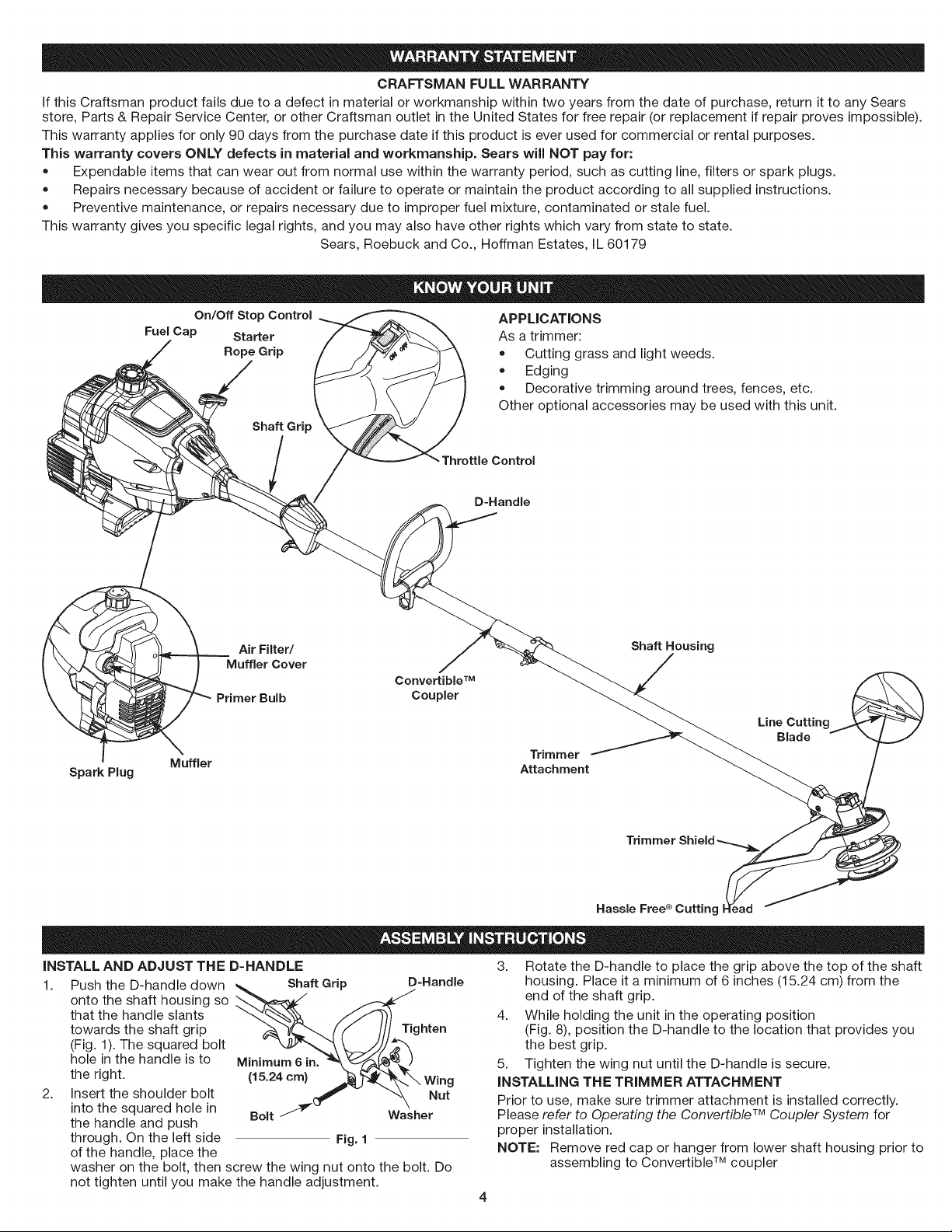
On/Off Stop Control
Fuel Cap Starter
Rope Grip
Shaft Grip
APPLICATIONS
As a trimmer:
• Cutting grass and light weeds.
Edging
Decorative trimming around trees, fences, etc.
Other optional accessories may be used with this unit.
Throttle Control
D-Handle
Spark Plug
Air Filter/ Shaft Housing
Muffler Cover
Convertible TM
Primer Bulb Coupler
Trimmer
Muffler Attachment
Line g
Blade
Trimmer Shield
Hassle Free ® Cutting d
INSTALL AND ADJUST THE D-HANDLE
1. Push the D-handle down Shaft Grip
onto the shaft housing so
that the handle slants
towards the shaft grip Tighten
(Fig. 1). The squared bolt
hole in the handle is to Minimum 6 in.
the right. (15.24 cm) Wing
2. Insert the shoulder bolt Nut
into the squared hole in
the handle and push Bolt Washer
through. On the left side Fig. 1
of the handle, place the
washer on the bolt, then screw the wing nut onto the bolt. Do
not tighten until you make the handle adjustment.
D=Handle
3. Rotate the D-handle to place the grip above the top of the shaft
housing. Place it a minimum of 6 inches (15.24 cm) from the
end of the shaft grip.
4. While holding the unit in the operating position
(Fig. 8), position the D-handle to the location that provides you
the best grip.
5. Tighten the wing nut until the D-handle is secure.
INSTALLING THE TRIMMER ATTACHMENT
Prior to use, make sure trimmer attachment is installed correctly.
Please refer to Operating the Convertible TM Coupler System for
proper installation.
NOTE: Remove red cap or hanger from lower shaft housing prior to
assembling to Convertible TM coupler
OILANDFUELMIXINGINSTRUCTIONS
Oldand/orimproperlymixedfuelarethemainreasonsfortheunitnot
runningproperly.Besuretousefresh,cleanunleadedfuel.Followthe
instructionscarefullyfortheproperfuel/oilmixture.
Definition of Blended Fuels
Today's fuels are often a blend of gasoline and oxygenates such as
ethanol, methanol, or MTBE (ether). Alcohol-blended fuel absorbs
water. As little as 1% water in the fuel can make fuel and oil
separate. It forms acids when stored. When using alcohol-blended
fuel, use fresh fuel (less than 60 days old).
Using Blended Fuels
If you choose to use a blended fuel, or its use is unavoidable, follow
recommended precautions:
= Always use the fresh fuel mix explained in your operator's manual
• Always agitate the fuel mix before fueling the unit
= Drain the tank and run the engine dry before storing the unit
Using Fuel Additives
The bottle of 2-cycle oil that came with your unit contains a fuel
additive which will help inhibit corrosion and minimize the formation of
gum deposits. It is recommended that you use our 2-cycle oil with this
unit. If unavailable, use a good 2-cycle oil de-signed for air-cooled
engines along with a fuel additive, such as STA-BIL_">Gas Stabilizer or
an equivalent. Add 0.8 oz. (23 ml) of fuel additive per gallon of fuel
according to the instructions on the container. NEVER add fuel
additives directly to the unit's fuel tank.
_ AUTION: For proper engine operation and maximum
reliability, pay strict attention to the oil and fuel mixing
instructions on the 2-cycle oil container. Using improperly
mixed fuel can severely damage the engine.
Thoroughly mix the proper ratio of 2-cycle engine oil with unleaded
gasoline in a separate fuel can. Use a 40:1 fuel/oil ratio. Do not mix
them directly in the engine fuel tank. See the table below for
specific gas and oil mixing
ratios.
NOTE: One gallon (3.8 liters) of
unleaded gasoline
mixed with one 3.2 oz.
(95 ml) bottle of 2-cycle
oil makes a 40:1 fuel/oil
ratio.
NOTE: Dispose of the old
fuel/oil mix in
accordance to
Federal, State and
Local regulations.
UNLEADED GAS
1 GALLON US
(3.8 LITERS}
1 LITER
A
2 CYCLE OIL
3.2 FL. OZ.
(95 ml}
25 ml
MIXING RATIO - 40:1
WARNING: Gasoline is extremely flammable, ignited
vapors may explode. Always stop the engine and allow it
to cool before filling the fuel tank. Do not smoke while
filling the tank. Keep sparks and open flames at a distance
from the area.
_lb ARNING: Remove fuel cap slowly to avoid injury from
fuel spray. Never operate the unit without the fuel cap
securely in place.
WARNING: Add fuel in a clean, well ventilated outdoor
area. Wipe up any spilled fuel immediately. Avoid creating
a source of ignition for spilt fuel. Do not start the engine
until fuel vapors dissipate.
,_ WARNING: Operate this unit only in a well-ventilatedoutdoor area. Carbon monoxide exhaust fumes can be
lethal in a confined area.
WARNING: Avoid accidental starting. Make sure you are
in the starting position when pulling the starter rope (Fig. 4).
To avoid serious injury, the operator and unit must be
in a stable position while starting.
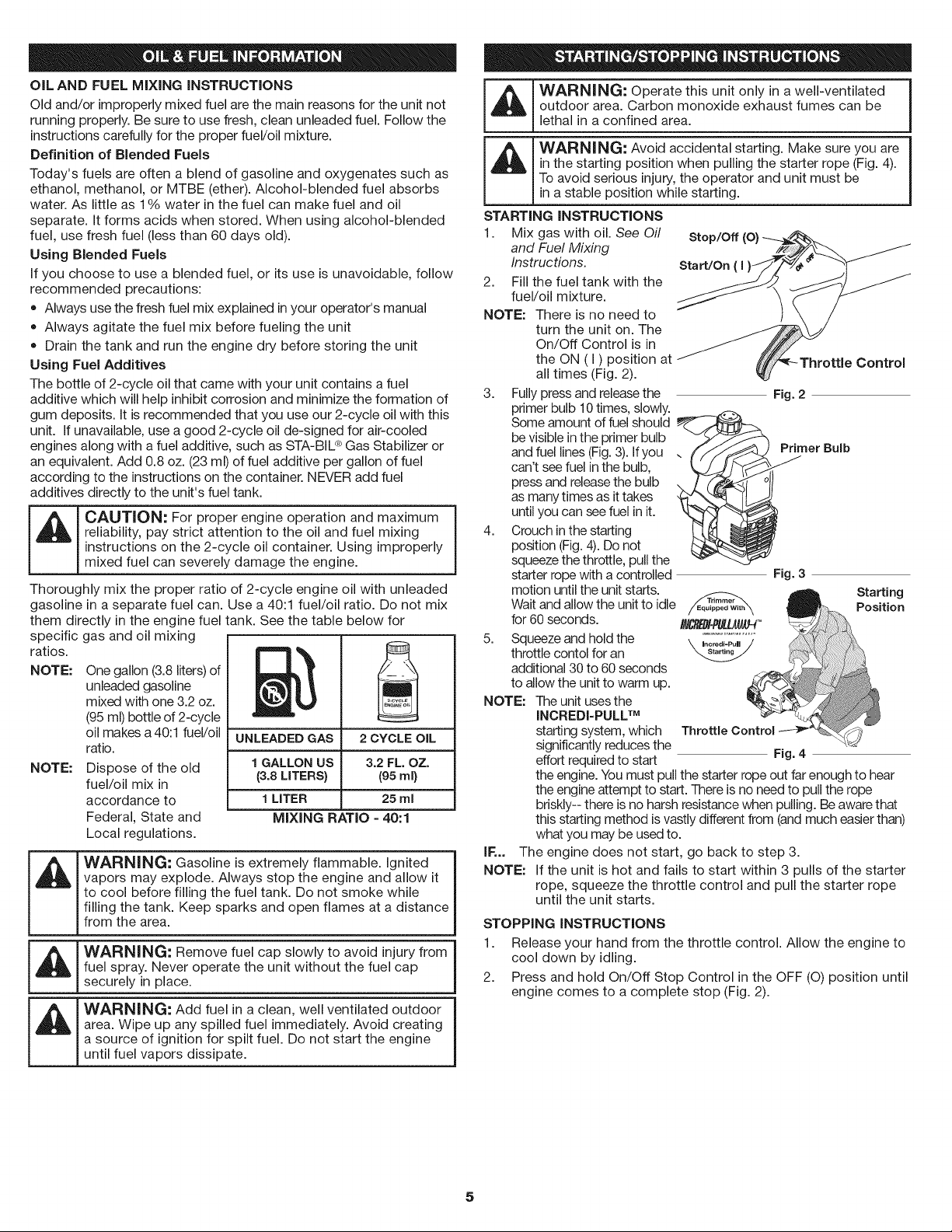
STARTING INSTRUCTIONS
1. Mix gas with oil. See Oil Stop/Off (O} ---_._/z_
and Fuel Mixing /_-Y/OL_ /
Instructions.
2. Fill the fuel tank with the
fuel/oil mixture.
NOTE: There is no need to
turn the unit on. The
On/Off Control is in
the ON (I) position at _ ////[i'_-Throttle Control
all times (Fig. 2). _J
3. Fully press and release the
primer bulb 10 times, slowly.
Some amount of fuel should
be visible in the primer bulb
and fuel lines (Fig.3). If you
can't see fuel in the bulb,
press and release the bulb
as many times as it takes
until you can see fuel in it.
4. Crouch in the starting
position (Fig. 4). Do not
squeeze the throttle, pull the
starter rope with a controlled
motion until the unit starts.
Wait and allow the unit to idle
for 60 seconds.
8,
NOTE:
Squeeze and hold the
throttle contol for an
additional 30 to 60 seconds
to allow the unit to warm up.
The unit uses the
INCREDI=PULLTM
starting system, which
significantly reduces the
effort required to start
Fig. 2
Primer Bulb
/
Fig. 3
Starting
Position
Fig. 4
the engine. You must pull the starter rope out far enough to hear
the engine attempt to start. There is no need to pull the rope
briskly-- there is no harsh resistance when pulling. Be aware that
this starting method is vastly different from (and much easier than)
what you may be used to.
IF... The engine does not start, go back to step 3.
NOTE: If the unit is hot and fails to start within 3 pulls of the starter
rope, squeeze the throttle control and pull the starter rope
until the unit starts.
STOPPING INSTRUCTIONS
1. Release your hand from the throttle control. Allow the engine to
cool down by idling.
2. Press and hold On/Off Stop Control in the OFF (O) position until
engine comes to a complete stop (Fig. 2).
5
OPERATING THE CONVERTIBLE TM COUPLER SYSTEM
WARNING: Before you begin using any attachment, read I
and understand the manual that came with the attachment.
IFollow all safety information contained within.
CAUTION: These attachments are to be snapped into I
the primary hole only. Using the wrong hole could lead to
1
personal injury or damage to the unit.
The Convertible TM coupler system enables the use of these optional
attachments.
• Edger
Cultivator
Turbo Blower
Brushcutter
Pole Saw
Blade Pruner
Hedge Trimmer
REMOVING THE TRIMMER ATTACHMENT OR OTHER ATTACHMENT
_ WARNING: To avoid serious personal injury and 1
damage to the unit, shut the unit off before removing or
installing attachment.
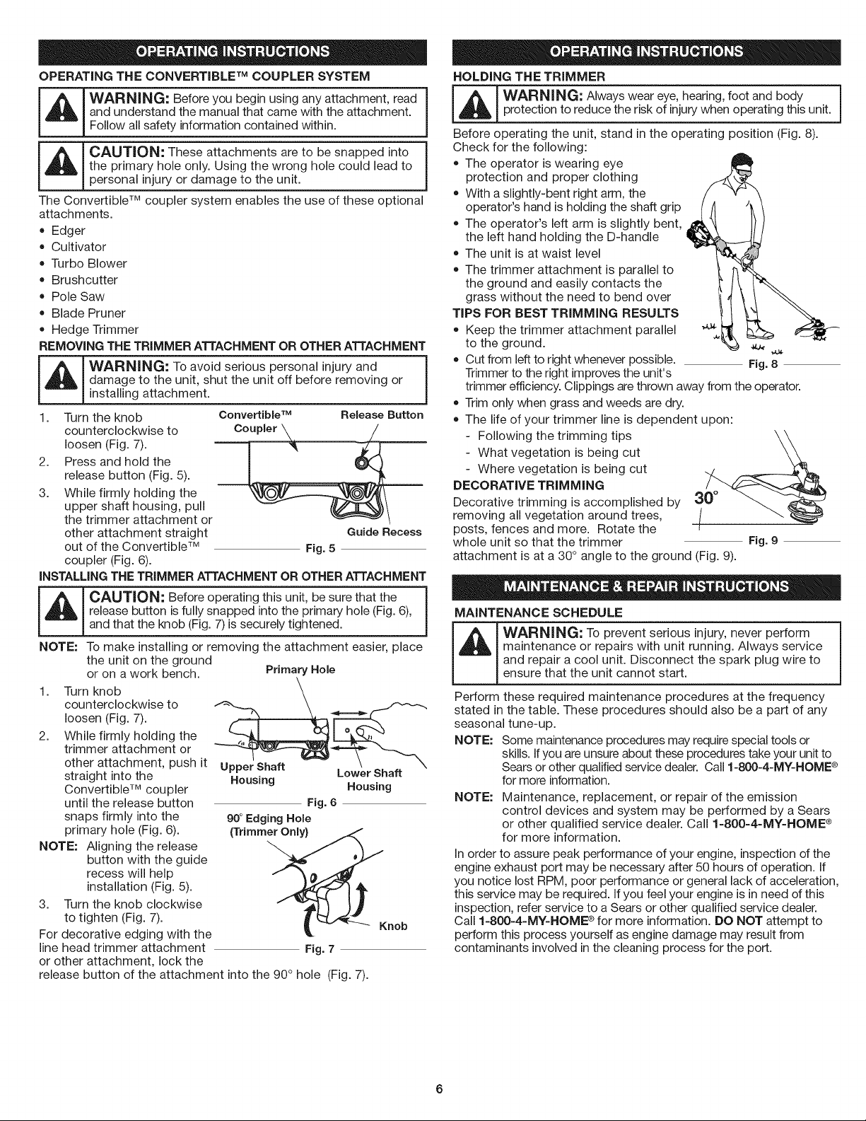
1. Turn the knob
counterclockwise to
loosen (Fig. 7).
2. Press and hold the
release button (Fig. 5).
3. While firmly holding the
upper shaft housing, pull
the trimmer attachment or
other attachment straight
out of the Convertible TM
coupler (Fig. 6).
Convertible TM Release Button
Guide Recess
Fig. 5
iNSTALLiNG THE TRIMMER ATTACHMENT OR OTHER ATTACHMENT
_ CAUTION: Before operating this unit, be sure that the
release button is fully snapped into the primary hole (Fig. 6),
1
and that the knob (Fig. 7) is securely tightened.
NOTE: To make installing or removing the attachment easier, place
the unit on the ground
or on a work bench. Primary Hole
1. Turn knob
counterclockwise to
loosen (Fig. 7).
2. While firmly holding the
trimmer attachment or
other attachment, push it
straight into the
Convertible TM coupler
until the release button
snaps firmly into the
primary hole (Fig. 6).
NOTE: Aligning the release
button with the guide
recess will help
installation (Fig. 5).
3. Turn the knob clockwise
to tighten (Fig. 7).
For decorative edging with the
line head trimmer attachment
or other attachment, lock the
Housing Housing
Fig. 6
90° Edging Hole
{Trimm_ ..... Knob
Fig. 7
release button of the attachment into the 90 ° hole (Fig. 7).
HOLDING THE TRIMMER
_L_ WARNING: Always wear eye, hearing, foot and body
protection to reduce the risk of injury when operating this unit.
Before operating the unit, stand in the operating position (Fig. 8).
Check for the following:
The operator is wearing eye
protection and proper clothing
With a slightly-bent right arm, the
operator's hand is holding the shaft grip
The operator's left arm is slightly bent,
the left hand holding the D-handle
The unit is at waist level
The trimmer attachment is parallel to
the ground and easily contacts the
grass without the need to bend over
TiPS FOR BEST TRIMMING RESULTS
• Keep the trimmer attachment parallel '_
to the ground.
Cut from left to right whenever possible. Fig. 8
Trimmer to the right improves the unit's
trimmer efficiency. Clippings are thrown away from the operator.
Trim only when grass and weeds are dry.
The life of your trimmer line is dependent upon:
Following the trimming tips
What vegetation is being cut
Where vegetation is being cut
DECORATIVE TRIMMING
Decorative trimming is accomplished by
removing all vegetation around trees,
posts, fences and more. Rotate the
whole unit so that the trimmer
attachment is at a 30 ° angle to the ground (Fig. 9).
MAINTENANCE SCHEDULE
WARNING: To prevent serious injury, never perform
maintenance or repairs with unit running. Always service
and repair a cool unit. Disconnect the spark plug wire to
ensure that the unit cannot start.
Perform these required maintenance procedures at the frequency
stated in the table. These procedures should also be a part of any
seasonal tune-up.
NOTE: Some maintenance procedures may require special tools or
skills. If you are unsure about these procedures take your unit to
Sears or other qualified service dealer. Call 1=800=4=MY=HOME®
for more information.
NOTE: Maintenance, replacement, or repair of the emission
control devices and system may be performed by a Sears
or other qualified service dealer. Call 1=800=4=MY=HOME ®
for more information.
In order to assure peak performance of your engine, inspection of the
engine exhaust port may be necessary after 50 hours of operation. If
you notice lost RPM, poor performance or general lack of acceleration,
this service may be required. If you feel your engine is in need of this
inspection, refer service to a Sears or other qualified service dealer.
Call 1=800=4-MY=HOME ® for more information. DO NOT attempt to
perform this process yourself as engine damage may result from
contaminants involved in the cleaning process for the port.
FREQUENCY MAINTENANCEREQUIRED SEE
Before starting Fill fuel tank with fresh fuel p. 5
engine
Every 10 hours Clean and re-oil air filter p. 7
Every 25 hours Check and clean spark arrestor p. 8
Check spark plug condition and gap p. 8
Every 50 hours Inspect exhaust port and spark p. 8
arrestor screen for clogging or
obstruction
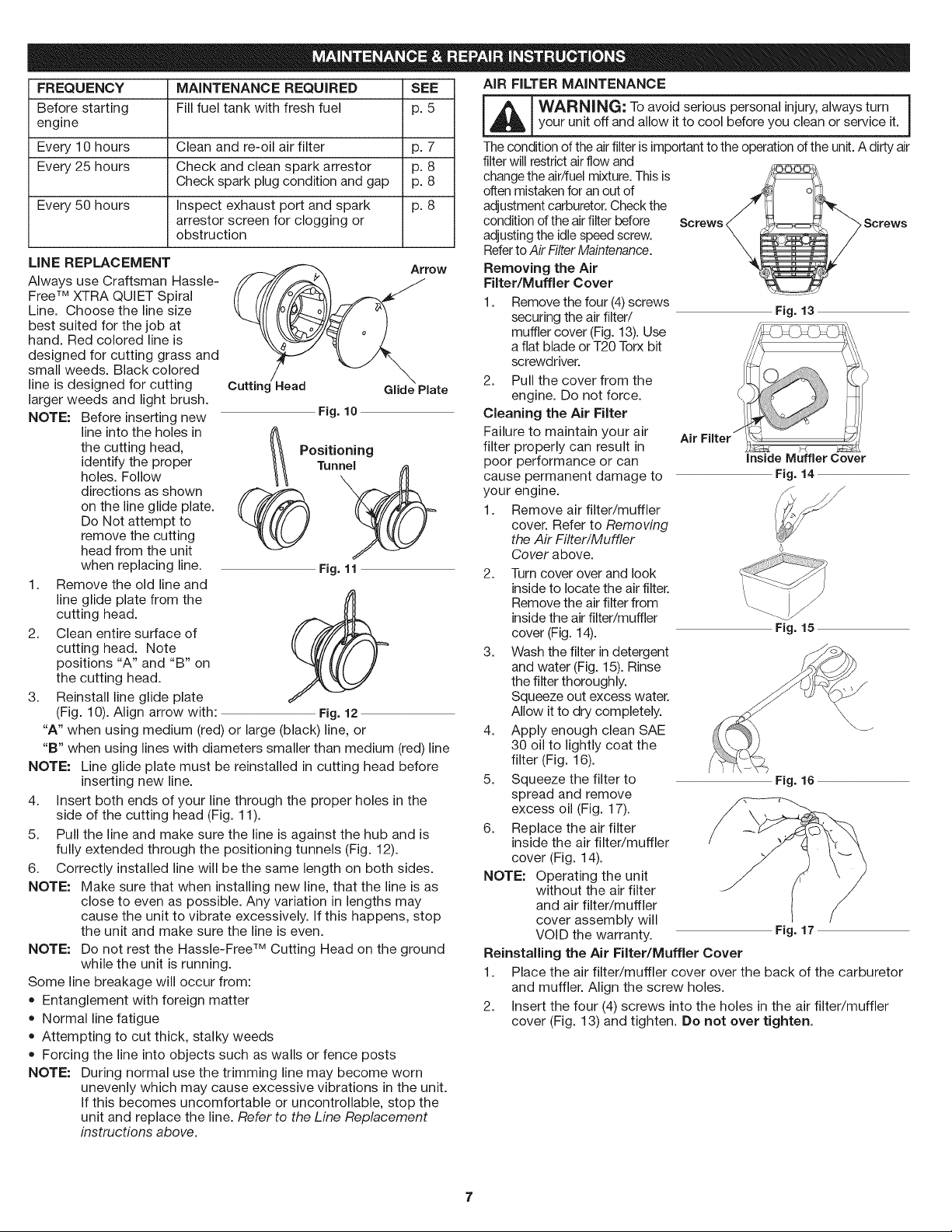
LINE REPLACEMENT
Always use Craftsman Hassle-
Free TM XTRA QUIET Spiral
Line. Choose the line size
best suited for the job at
hand. Red colored line is
designed for cutting grass and
small weeds. Black colored
line is designed for cutting
larger weeds and light brush.
NOTE: Before inserting new
line into the holes in
the cutting head,
identify the proper
holes. Follow
directions as shown
Arrow
Cuttinc Head
Glide Plate
on the line glide plate.
Do Not attempt to
remove the cutting
head from the unit
when replacing line.
1. Remove the old line and
line glide plate from the
cutting head.
2. Clean entire surface of
cutting head. Note
positions "A" and "B" on
the cutting head.
3. Reinstall line glide plate
(Fig. 10). Align arrow with:
Fig. 10
_ P°siTtin°nenlng
Fig. 11
Fig. 12
"A" when using medium (red) or large (black) line, or
"B" when using lines with diameters smaller than medium (red) line
NOTE: Line glide plate must be reinstalled in cutting head before
inserting new line.
4. insert both ends of your line through the proper holes in the
side of the cutting head (Fig. 11).
5. Pull the line and make sure the line is against the hub and is
fully extended through the positioning tunnels (Fig. 12).
6. Correctly installed line will be the same length on both sides.
NOTE: Make sure that when installing new line, that the line is as
close to even as possible. Any variation in lengths may
cause the unit to vibrate excessively. If this happens, stop
the unit and make sure the line is even.
NOTE: Do not rest the Hassle-Free TM Cutting Head on the ground
while the unit is running.
Some line breakage will occur from:
• Entanglement with foreign matter
Normal line fatigue
Attempting to cut thick, stalky weeds
Forcing the line into objects such as walls or fence posts
NOTE: During normal use the trimming line may become worn
unevenly which may cause excessive vibrations in the unit.
If this becomes uncomfortable or uncontrollable, stop the
unit and replace the line. Referto the Line Replacement
instructions above.
AIR FILTER MAINTENANCE
_L_ WARNING: To avoid serious personal injury, always turn
your unit off and allow it to cool before you clean or service it.
The condition of the air filter is important to the operation of the unit. A dirty air
filter will restrict air flow and
change the air/fuel mixture. This is
often mistaken for an out of
adjustment carburetor. Check the
condition of the air filter before Screws ,Screws
adjusting the idle speed screw.
Referto Air Filter Maintenance.
Removing the Air
Filter/Muffler Cover
1.
Remove the four (4)screws
securing the air filter/
muffler cover (Fig. 13). Use
a flat blade or T20 Torx bit
screwdriver.
2. Pull the cover from the
engine. Do not force.
Cleaning the Air Filter
Failure to maintain your air
filter properly can result in
poor performance or can
cause permanent damage to
your engine.
1. Remove air filter/muffler
cover. Refer to Removing
the Air Filter/Muffler
Cover above.
Fig. 13
inside Muffler Cover
Fig. 14
2. Turn cover over and look
inside to locate the air filter.
Remove the air filter from
inside the air filter/muffler
cover (Fig. 14).
3. Wash the filter in detergent
and water (Fig. 15). Rinse
the filter thoroughly.
Squeeze out excess water.
Allow it to dry completely.
4. Apply enough clean SAE
30 oil to lightly coat the
filter (Fig. 16).
5. Squeeze the filter to
spread and remove
excess oil (Fig. 17).
6. Replace the air filter
inside the air filter/muffler
cover (Fig. 14).
NOTE: Operating the unit
without the air filter
and air filter/muffler
cover assembly will
VOID the warranty.
Reinstalling the Air Filter/Muffler Cover
1.
2.
Fig. 15
Fig. 16
Fig. 17
Place the air filter/muffler cover over the back of the carburetor
and muffler. Align the screw holes.
Insert the four (4) screws into the holes in the air filter/muffler
cover (Fig. 13) and tighten. Do not over tighten.
7
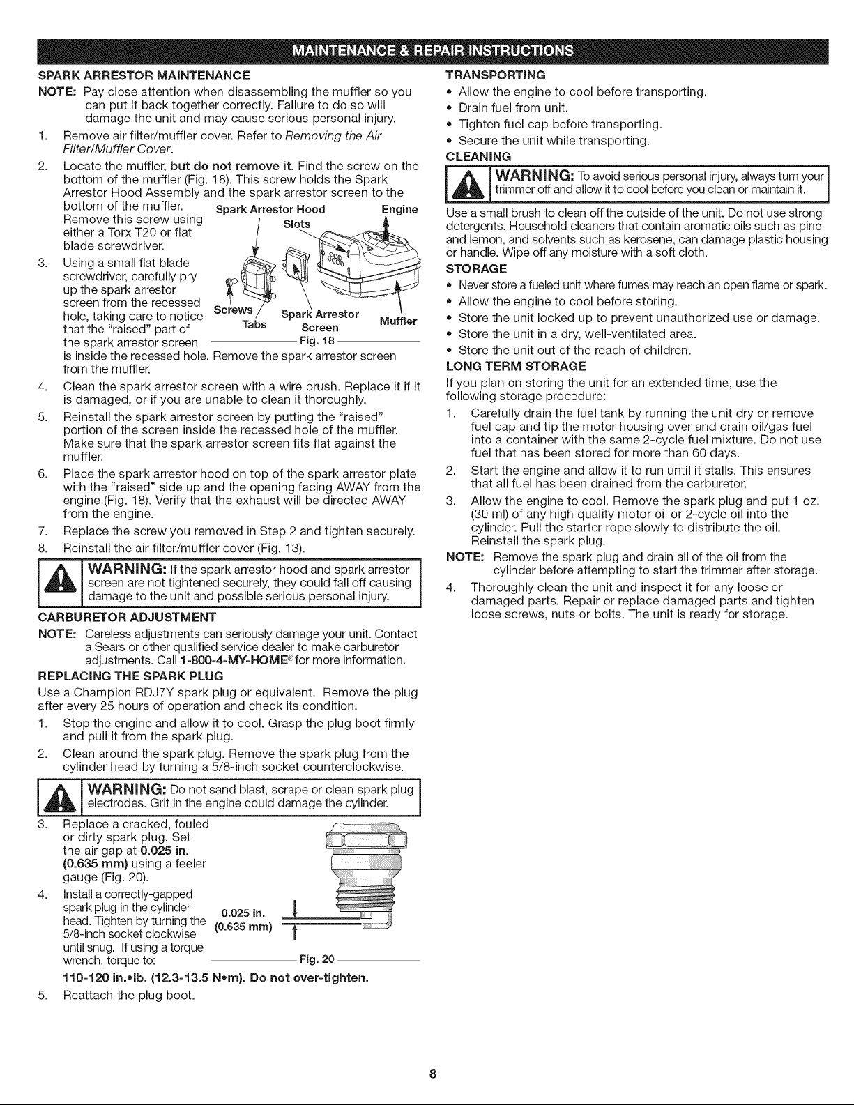
SPARKARRESTOR MAINTENANCE
NOTE: Pay close attention when disassembling the muffler so you
can put it back together correctly. Failure to do so will
damage the unit and may cause serious personal injury.
1. Remove air filter/muffler cover. Refer to Removing the Air
Filter/Muffler Cover.
2.
3.
Locate the muffler, but do not remove it. Find the screw on the
bottom of the muffler (Fig. 18). This screw holds the Spark
Arrestor Hood Assembly and the spark arrestor screen to the
bottom of the muffler.
Remove this screw using
either a Torx T20 or flat
blade screwdriver.
Using a small flat blade
screwdriver, carefully pry
up the spark arrestor
screen from the recessed
hole, taking care to notice
that the "raised" part of
the spark arrestor screen
Spark Arrestor Hood Engine
is,o
Tabs Screen Muffler
Fig. 18
is inside the recessed hole. Remove the spark arrestor screen
from the muffler.
4.
5.
Clean the spark arrestor screen with a wire brush. Replace it if it
is damaged, or if you are unable to clean it thoroughly.
Reinstall the spark arrestor screen by putting the "raised"
portion of the screen inside the recessed hole of the muffler.
Make sure that the spark arrestor screen fits flat against the
muffler.
6. Place the spark arrestor hood on top of the spark arrestor plate
with the "raised" side up and the opening facing AWAY from the
engine (Fig. 18). Verify that the exhaust will be directed AWAY
from the engine.
7. Replace the screw you removed in Step 2 and tighten securely.
8. Reinstall the air filter/muffler cover (Fig. 13).
L_J WARNING: If the spark arrestor hood and spark arrestor
screen are not tightened securely, they could fall off causing
J
damage to the unit and possible serious personal injury.
CARBURETOR ADJUSTMENT
NOTE: Careless adjustments can seriously damage your unit. Contact
a Sears or other qualified service dealer to make carburetor
adjustments. Call 1-800-4-MY-HOME">for more information.
REPLACING THE SPARK PLUG
Use a Champion RDJ7Y spark plug or equivalent. Remove the plug
after every 25 hours of operation and check its condition.
1. Stop the engine and allow it to cool. Grasp the plug boot firmly
and pull it from the spark plug.
2. Clean around the spark plug. Remove the spark plug from the
cylinder head by turning a 5/8-inch socket counterclockwise.
_ WARN,NG: Do not sand blast, scrape or clean spark plug ]
electrodes. Grit in the engine could damage the cylinder.
3. Replace a cracked, fouled
or dirty spark plug. Set
the air gap at 0.025 in.
(0.635 ram} using a feeler
gauge (Fig. 20).
4. Install a correctly-gapped
spark plug in the cylinder 0.025 in.
head. Tighten by turning the (0.635 ram)
5/8-inch socket clockwise |
until snug. If using a torque
wrench, torque to: Fig. 20
110-120 in.olb. (12.3-13.5 Nora). Do not over-tighten.
5. Reattach the plug boot.
TRANSPORTING
Allow the engine to cool before transporting.
Drain fuel from unit.
Tighten fuel cap before transporting.
Secure the unit while transporting.
CLEANING
WARNING: To avoid serious personal injury, always turn your I
tr miner off and a ow t to coo before you c ean or manta n t.
Use a small brush to clean off the outside of the unit. Do not use strong
detergents. Household cleaners that contain aromatic oils such as pine
and lemon, and solvents such as kerosene, can damage plastic housing
or handle. Wipe off any moisture with a soft cloth.
STO RAG E
Never store a fueled unit where fumes may reach an open flame or spark.
Allow the engine to cool before storing.
Store the unit locked up to prevent unauthorized use or damage.
Store the unit in a dry, well-ventilated area.
Store the unit out of the reach of children.
LONG TERM STORAGE
If you plan on storing the unit for an extended time, use the
following storage procedure:
1. Carefully drain the fuel tank by running the unit dry or remove
fuel cap and tip the motor housing over and drain oil/gas fuel
into a container with the same 2-cycle fuel mixture. Do not use
fuel that has been stored for more than 60 days.
2. Start the engine and allow it to run until it stalls. This ensures
that all fuel has been drained from the carburetor.
3. Allow the engine to cool. Remove the spark plug and put 1 oz.
(30 ml) of any high quality motor oil or 2-cycle oil into the
cylinder. Pull the starter rope slowly to distribute the oil.
Reinstall the spark plug.
NOTE: Remove the spark plug and drain all of the oil from the
cylinder before attempting to start the trimmer after storage.
4. Thoroughly clean the unit and inspect it for any loose or
damaged parts. Repair or replace damaged parts and tighten
loose screws, nuts or bolts. The unit is ready for storage.

PROBLEM
Primer bulb wasn't pressed enough
Old or improperly mixed fuel
Plugged spark arrestor
The outside temperature is above 90 ° F
SOLUTION
Press primer bulb fully and slowly 10 times
Drain gas tank and add fresh fuel mixture
Clean or replace spark arrestor
Pull the starter rope up to 10-15 times
Old or improperly mixed fuel
Old or improperly mixed fuel
Trimmer attachment bound with grass
Plugged spark arrestor
Drain gas tank and add fresh fuel mixture
Drain gas tank and add fresh fuel mixture
Stop the engine and clean the trimmer attachment
Clean or replace spark arrestor
Old or improperly mixed fuel
Air filter is plugged
Plugged spark arrestor
Drain gas tank and add fresh fuel mixture
Replace or clean air filter
Clean or replace spark arrestor
9
EngineType.................................................................................... Air-Cooled,2-Cycle
Displacement.................................................................................... 31.5cc(1.95cuin.)
IdleSpeedRPM.................................................................................. 2,600- 3,600rpm
OperatingRPM........................................................................................ 6,800+rpm
IgnitionType...................................................................................... ElectronicIgnition
IgnitionSwitch...................................................................................... RockerSwitch
SparkPlugGap................................................................................. 0.025in.(0.635mm)
SparkPlug......................................................................... ChampionRDJ7Yorequivalentplug
Lubrication......................................................................................... Fuel/OilMixture
Fuel/OilRatio................................................................................................ 40:1
Carburetor................................................................................... Diaphragm,All-Position
Starter............................................................................. Incredi-PullTM Starting Auto Rewind
Muffler .......................................................................................... Baffled with Guard
Throttle ....................................................................................... Manual Spring Return
Fuel Tank Capacity ................................................................................... 13 oz. (384 ml)
Drive Shaft Housing ................................................................ Steel Tube (Craftsman Convertible TM)
Throttle Control ................................................................................... Finger-Tip Trigger
Approximate Unit Weight (No fuel, with Hassle Free®,shield, and D-handle) ........................................ 14 Ibs. (6 kg)
Trimmer Mechanism .............................................................................. Hassle FreeTM Head
Trimming Line .................................................................... Hassle Free TM XTRA QUIET Spiral Line
* All specifications are based on the latest product information available at the time of printing. We reserve the right to make changes at
any time without notice.
REPAIR PROTECTION AGREEMENTS
Congratulations on making a smart purchase. Your new Craftsman® product is designed and manufactured for years of dependable
operation. But like all products, it may require repair from time to time. That's when having a Repair Protection Agreement can save you
money and aggravation.
Here is what the Repair Protection Plan Agreement includes:
[] Expert service by our 10,000 professional repair specialists
[] Unlimited service and no charge for parts and labor on all covered repairs
[] Product replacement up to $1500 if your cover product can not be fixed
[] Discount of 10% from regular price of service and related installed parts not covered by the agreement; also, 10% off regular price of
preventive maintenance checks
[] Fast help by phone - we call it Rapid Resolution - phone support from a Sears representative. Think of us as a "talking owner's maunal."
Once you purchase the Repair Protection Agreement, a simple phone call is all that it takes for you to schedule service. You can call anytime
day or night, or schedule a service appointment online.
The Repair Protection Agreement is a risk-free purchase. If you cancel for any reason during the product warranty period, we will provide a full refund.
Or a prorated refund anytime after the prodduct warranty period expires. Purchase you Repair Protection Agrrement today!
Some limitations and exclusions apply. For prices and additional information call 1-800-827-6655.
*Coverage in Canada varies on some items. For full datails call Sears Canada at 1-800-361-6665.
Sears installation Service
For Sears professional installation of home appliances, garage door openers, water heaters, and other major home items, in the U.S.A. or
Canada call 1-800-4-MY-HOME ®.
10

Manual del Operador
2-Tiempos
WEEDWACKER_ RECORTADOR A GASOLINA
Model No. 316.791860
U_U_VASLE STA#FINtt EA SE _
* SEGURIDAD
* MONTAJE
* FUNCIONAMIENTO
* MANTENIMIENTO
* LISTADO DE PIEZAS
PRECAUCION: Lea eJ manual
del operador y siga todas Jas
advertencias e instrucciones
de seguridad.
Sears, Roebuck and Co., Hoffman Estates, JL60179, U.S.A.
Visite nuestro sitio web: www.sears.com/craftsman
769-04884 P01 5/09
PROPOSlCION 65 DE CALIFORNIA Toda la informaci6n, las ilustraciones y las especificaciones contenidas en
LAS EMISIONES DEL MOTOR DE ESTE PRODUCTO CONTIENEN
SUBSTANCIAS QUIMICAS QUE EL ESTADO DE CALiFORNiA
CONOCE COMO CAUSANTES DECANCER, DEFECTOS DE
NACIMIENTO U OTROS DA_IOS REPRODUCTIVOS.
INDICE DE CONTENIDOS
Normas para una operaci6n segura ....................... 12
Garantia ............................................. 14
Conozca su unidad .................................... 14
Instrucciones de ensamble .............................. 14
Informaci6n del aceite y del combustible ................... 15
Instrucciones de arranque y apagado ...................... 15
Instrucciones de operaci6n .............................. 16
Instrucciones de mantenimiento y reparaci6n ............... 17
Limpieza y almacenamiento ............................. 18
Resoluci6n de problemas ............................... 19
Especificaciones ...................................... 20
Lista de piezas ....................................... 22
Numeros de servicio ......................... Contraportada
PARAC H ISPAS
NOTA:Para los usuariosen tierras forestaies de los EE.UU.yen losestados
de California, Maine, Oregon y Washington. Todos los terrenosforestales de
losEE.UU.y el estado de California(C6digosde RecursosPOblicos4442y 4443),
Oregony Washington,requierenpot decreto,que ciertos motores de combusti6n
internaque se hagan funcionar en zonas boscosas y/o zonas cubiertas por
pastizales,esten equipados con un parachispas,que sean mantenidos en buen
estado de funcionamiento o que el motor sea construido, este equipado y sea
mantenido para evitar incendios.Consulte los reglamentos pertinentes a esos
requisitos con las autoridades estatales o locales.El incumplimientode esos
requisitospuede responsabilizarleo someterlea laimposici6nde unamulta. Esta
unidadfue equipada en lafAbrica con un parachispas.Si requieresustituci6n,
hay una Pantalla Parachispas disponible, Pieza #753=05169al contactar el
departamento de servicio.
este manual se basan en la informaci6n mas reciente disponJble en el
momento de impresi6n del manual. Nos reservamos el derecho de hacer
cambios en cualquier momento sin aviso previo.
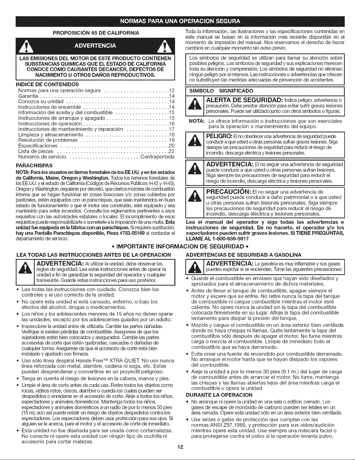
Los simbolos de seguridad se utilizan para Ilamar su atenci6n sobre I
posibles peligros. Los sfmbolos de seguridad y sus explicaciones merecen I
toda su atenci6n y comprensi6n. Los s[mbolos de seguridad no efiminan I
ningun peligro por si mismos. Las instrucciones o advertencias que ofrecen I
no substituyen las medidas adecuadas de prevenci6n de accidentes. J
SIMBOLO SIGNIFICADO
ALERTA DE SEGURIDAD: Indicapeligro, advertencia o
precauci6n. Debeprestar atenci6n para evitarsufrir graves lesiones
personales. Puedeser utilizadojunto con otros simbolos o figuras.
NOTA: Le ofrece informaci6n o instrucciones que son esenciales
para la operaci6n o mantenimiento del equipo.
PELIGRO: Elno obedecer una advertenciade seguridadpuede
conducir a que usted u otras personassufrangraves lesiones.Siga
siemprelas precaucionesde seguridad para reducirel riesgode
incendio,descargaelectricay lesionespersonales.
ADVERTENCIA: El no seguJr una advertencia de seguridad
puede conducir a que usted u otras personas sufran lesiones.
Siga siempre las precauciones de seguridad para reducir el
rieego de incendio,descarga electrica y lesiones personales.
811
PREOAUCION: El no seguir una advertencia de
seguridad puede conducir a da_o patrimonial o a que usted
u otras personas sufran lesiones personales. Siga siempre
las precauciones de seguridad para reducir el riesgo de
incendio, descarga electrica y lesiones personales.
Lea el manual del operador y sJga todas las advertencias e
instrucciones de seguridad. De no hacerlo, el operador y/o los
espectadores pueden sufrir graves lesiones. Sl TIENE PREGUNTAS,
LLAME AL 1=800=659=5917
• IMPORTANTE INFORMACION DE SEGURIDAD •
LEA TODAS LAS INSTRUCCIONES ANTES DE LA OPERACION
I _ I ADVERTENCIA: AI utilizarla unidad, debe observar las
reglas de seguridad. Lea estas instruccionesantes de operar la
unJdada fin de garantJzarla seguridad del operador y cualquier
transeunte. Guarde estas instrucciones para uso posterior.
• Lea todas las instrucciones con cuidado. Conozca bien los
controles y el uso correcto de la unidad.
No opere esta unidad siesta cansado, enfermo, o bajo los
efectos del alcohol, drogas o medicamentos.
Los ni_os y los adolescentes menores de 15 a_os no deben operar
las unidades, excepto por los adolescentes guiados por un adulto.
Inspeccione la unidad antes de utJlizarla.Cambie las partes da_adas.
Verifiquesi existen perdidas de combustible. Asegurese de que los
sujetadores esten bien colocados y asegurados. Cambie las partes
accesorias de corte que esten quebradas, cascadas o da_adas de
cualquier form& Asegurese de que el accesorJode corte esta bien
instalado y ajustado con firmeza.
Use s61o linea despiral Hassle Free TM XTRA QUIET. No use nunca
linea reforzada con metal, alambre, cadena ni soga, etc. Estas
pueden desprenderse y convertirse en un proyectil peligroso.
Tenga en cuenta el riesgo de lesiones en la cabeza, manos y pies.
Limpie el Areade corte antes de cada uso. Retiretodos los objetos como
rocas, vidrios rotos, clavos, alambre o cuerda los cuales pueden ser
despedJdoso enredarse en el accesorJode corte. Aleje a todos los ni_os,
espectadores y animales domesticos. Mantenga todos los ni_os,
espectadores y animales domesticos a un radio de por Io menos 50 pies
(15 m); aun asf puede existir un riesgo de objetos despedidos contra los
espectadores. Los espectadores deben usar proteccbn para sus ojos. Si
alguien se le acerca, pare el motor y el accesorio de corte de inmediato.
Esta unidad no fue dise_ada para ser usada como cortamalezas.
No conecte ni opere esta unidad con ningQn tipo de cuchilla ni
accesorio para cortar malezas.
ADVERTENCIAS DE SEGURIDAD A GASOLINA
[_ A[:)VERTI=I_CIA: La gasolinaes muy inf'amabley sus gases jpueden explotar si se encienden.Tome lassiguientesprecauciones:
Guarde el combustible en envases que hayan sido dise_ados y
aprobados para el almacenamiento de dichos materiales.
Antes de Ilenar el tanque de combustible, apague siempre el
motor y espere que se enfrie. No retire nunca la tapa del tanque
de combustible ni cargue combustible mientras el motor este
caliente. No opere nunca la unidad sin la tapa del combustible
colocada firmemente en su lugar. Afloje la tapa del combustible
lentamente para disipar la presi6n del tanque.
Mezcle y cargue el combustible en un Area exterior bien ventilada
donde no haya chispas ni llamas. Quite lentamente la tapa del
combustible s61o despues de apagar el motor. No fume mientras
carga o mezcla el combustible. Limpie de inmediato todo el
combustible que se haya derramado.
Evite crear una fuente de encendido pot combustible derramado.
No arranque el motor hasta que se hayan disipado los vapores
del combustible.
Aleje la unidad a pot Io menos 30 pies (9.1 m.) del lugar de carga
de combustible antes de arrancar el motor. No fume, mantenga
las chispas y las llamas abiertas lejos del Area mientras carga el
combustible u opera la unidad.
DURANTE LA OPERACION
• No arranque ni opere la unidad en una sala o edificio cerrado. Los
gases de escape de mon6xido de carbono pueden ser letales en un
Area cerrada. Opere esta unidad s61oen un b,rea exterior bien ventilada.
Use lentes o gafas de protecci6n que cumplan con las
normas ANSI Z87.1989, y protecci6n para sus oidos/audici6n
mientras opere esta unidad. Use siempre una mascara facial o
para protegerse contra el polvo si la operaci6n levanta polvo.
12
• Usepantaloneslargosygruesos,botas,guantesycamisademanga
larga.Nouseropaholgada,alhajas,pantalonescortos,sandaliasni
estedescalzo.Sostengaelcabellosobreelniveldeloshombros.
Laprotecci6naccesoriadecortedebeestarsiemprecolocadaen
sulugarmientrasoperelaunidad.Nooperelaunidadconlasdos
lineasdecorteextendidas,y lalineacorrectainstalada.No
extiendalalineadecortemasaliadelaIongituddelaprotecci6n.
Estaunidadcuentaconunembrague.Elaccesoriodecorte
permaneceestacionariocuandoelmotorestaenmarchalenta.Sino
Iohace,hagaajustarlaunidadporunt6cnicodeservicioautorizado.
AjustelamanijaenDasutama_odemodoquelebrindeelmejoragarre.
AsegQresedequeelaccesoriodecortenoestaencontactocon
ningQnobjetoantesdearrancarlaunidad.
UselaunidadQnicamenteconlaluzdeldiaoconbuenaluzartificial.
Evitearrancarlaunidadaccidentalmente.Col6queseenposici6n
deiniciosiemprequetiredelacuerdadearranque.Eloperadory
launidaddebenestarenunaposici6nestablealcomenzar.Lea
lasinstruccionesdeArranqueyApagado.
Uselaherramientaadecuada.Nouseestaunidadparaninguna
tareaparalacualnohasidodise_ada.
Sostengasiemprelaunidadconambasmanosmientrasesteen
funcionamiento.Sostengaconfirmezatantoelmangocomola
manijaauxiliar.
Mantengalasmanos,lacaraylospieslejosdetodaslaspartes
m6viles.Nointentetocarnidetenerelaccesoriodecortemientrasgira.
Notoqueelmotor,elbastidordelengranajenielsilenciador.
Estaspartessecalientanmuchoconlaoperaci6n.Luegode
apagarlaunidad,permanecencalientesduranteuntiempobreve.
Noopereelmotoraunavelocidadmayorquelanecesariapara
cortar,recortarorecortarlosbordes.Nohagafuncionarelmotor
aaltavelocidadmientrasnoestacortando.
Apaguesiempreelmotorcuandodemoreelcorteomientras
caminaentrezonasdecorte.
SigolpeaoseenredaconalgQnobjetoextra,o,apagueelmotorde
inmediatoyverifiquesihayda_os.Reparetodoslosda_osantesde
volveraintentaroperarlaunidad.Nooperelaunidadsitienepiezas
flojasoda_adas.
Apagueelmotorpararealizartodoelmantenimiento,
reparacionesocambiodelaccesoriodecorteuotrosaccesorios.
Uses61opiezasyaccesoriosderepuestodelfabricantedelequipo
originalparaestaunidad.Puedeobtenerlosensuproveedordeservicio
autorizado.Elusodepiezasyaccesoriosquenosonequipoorigina;
puedecausargraveslesionesaloperadoroelda_odesuunidad,yla
cancelaci6ndesugarantfa.
Mantengalaunidadlibredevegetaci6nyotrosmateriales.
Puedenalojarseentreelaccesoriodecorteylaprotecci6n.
Parareducirelriesgodeincendio,cambielossilenciadoresy
amortiguadoresdechispasdefectuosos,mantengaelmotoryelsilenciador
libredepasto,hojas,grasaexcesivaoacumulacionesdecarbono.
OTRASADVERTENCIASDE SEGURIDAD
= No guarde nunca la unidad con combustible en el tanque en un edificio
donde los gases puedan Ilegar a una llama abierta o a una chispa.
Espere que el motor se enfrie antes de guardar o transportar la
unidad. AsegOrese de que la unidad este segura al transportarla.
Guarde la unidad bajo Ilave en un lugar adecuado y seco para
evitar que sea usada por personas no autorizadas y se da_e,
fuera del alcance de los ni_os.
Nunca moje ni rode la unidad con agua ni con ningun otro Ifquido.
Mantenga las manijas secas, limpias y sin residuos. Limpie la unidad
luego de cada uso, lea las instrucciones de Limpieza y Almacenamiento.
Guarde estas instrucciones. ConsQItelas con frecuencia y
utilicelas para ense_ar a otros usuarios. Si le presta esta unidad a
alguien, prestele tambien estas instrucciones.
CONSERVE ESTAS INSTRUCCIONES
='SIMBOLOS DE SEGURIDAD E INTERNACIONALES "
Este manual del operador describe los simbolos y figuras de seguridad e internacionales que pueden aparecer en este producto. Lea el
manual del operador para obtener informaci6n completa acerca de la seguridad, ensamble, operaci6n y mantenimiento y reparaci6n.
SIMBOLO SIGNIFICADO SIMBOLO SIGNIFICADO
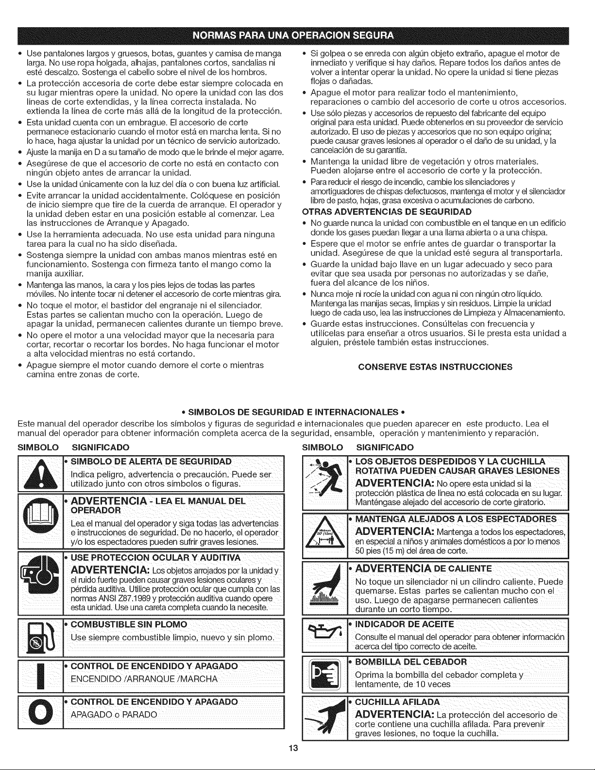
_, "' SIMBOLO DE ALERTA DE SEGURIDAD
_ !ndica peligr01 advertencia o precauci6n: Puede set
_ utilizado junto con otros s[mbolos o figurasl
, ADVERTENCIA : LEA EL MANUAL DEL
OPERADOR
CeaelmanualdeioPeradoryS gat0das advertenciaS
e instrucciones de seguridad: De no hacerlo, el operador
y/o los espectadores pueden sufrir graves lesiones.
,,USE PROTECCION OCULAR Y AUDITIVA
ADVERTEN CIA: LoSobjet0sarrojad0s pot la Unidady
el ruido fuerte pueden Causargraves !esionesocularesy
p_rdida auditiva. Utilice Protecci6n ocular que cumpla con las
normas ANSI Z87;1989 y protecci6n auditiva cuando opere
esta unidad. Use una caretacompleta cuando la necesite.
% •COMBUST BLESINPLOMO
Oses'e pre
I
| CONTROLDEENCEND DOy APAGADO
[ ENCEND DO/ARRANQUE !MARCHA
CONTROL DE ENCENDIDO Y APAGADO
APA AOOoPA AOO
.,,17..,,._l_ " LOS OBJETOS DESPEDIDOSY LA CUCHILLA
//_---_'_ ROTATIVA PUEDEN CAUSAR GRAVES LESIONES
___f._,, ADVERTENCIA: No opere esta unidad si la
protecci6n plAstica de linea no estA colocada en su lugar.
Mantengase alejado del accesorio de corte giratorio.
, MANTENGA ALEJADOS A LOS ESPECTADORES
ADVERTENCIA: Mantenga a todos los espectadores,
en especial a ni_os y animales dom6sticos a por Io menos
50 pies (15 m) del Area de corte.
, ADVERTENOIA DE CALIENTE
No toque un silenciador nun cilindro caliente Puede
quemarse. Estas partes se calientan mucho con el
uso. Luego de apagarse permanecen calientes
durante un corto tiempo.
l • INDICADOR DE ACEITE
_1 Consulte el manual del operador para obtener informaci6n
.[ acerca de t po correcto de ace te.
' • BOMBILLA DEL CEBADOR
_" I Oprima la bombilla del cebador completa y
J entamente, de 10 veces
'= CUCNILLA AFILADA
..__ ADVERTENCIA: La protecci6n del accesorio de
-_ corte contiene una cuchilla afilada. Para prevenir
graves lesiones, no toque la cuchilla.
13
GARANTJATOTAL DE CRAFTSMAN
Si este producto de Craftsman Professional falla debido a un defecto en el material o en la mano de obra dentro de un periodo de tres a_os
a partir de la fecha de compra, devuelvalo a cualquier tienda o Centro de Servicio de Piezas y Reparaciones Sears u otto establecimiento de
Craftsman en los Estados Unidos para que sea reparado sin costo alguno (o ser reemplazado si resulta imposible repararlo).
Esta garantia se aplica solamente durante 90 dias si este producto en algQn momento se utiliza para fines comerciales o de alquiler.
Esta garant{a abarca SOLAMENTE los defectos en el material o en la mano de obra. Sears NO pagar_:
• Los articulos consumibles que se desgasten debido al uso normal dentro del periodo de garantia.
• Las reparaciones necesarias debidas a accidente asi como por no operar o no mantener el equipo de acuerdo con todas las instruccionesprovistas.
• Mantenimiento preventivo, o las reparaciones necesarias debido a mezcla incorrecta de combustible, combustible contaminado o viejo.
Esta garantia le concede a usted derechos legales especificos, y usted pudiera tener otros derechos que varian de un estado a otro.
Sears, Roebuck and Co., Hoffman Estates, IL 60179
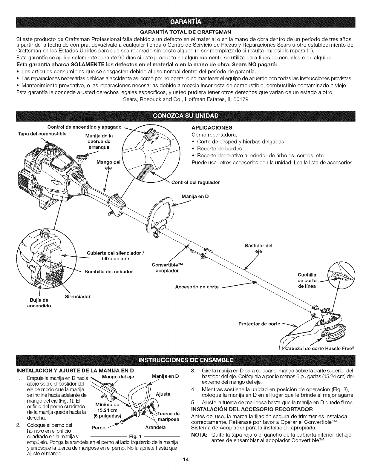
Control de encendido y apagado
Tapa del combustible Manija de la
cuerda de
arranque
Mango del
eje
APLICACIONES
Como recortadora;
Corte de cesped y hierbas delgadas
Recorte de bordes
Recorte decorativo alrededor de arboles, cercos, etc.
Puede usar otros accesorios con la unidad. Lea la lista de accesorios.
Control del regulador
Manija en D
Bujfa de
encendido
Cubierta del silenciador /
filtro de aire
Bombilla del cebador
Silenciador
Convertible TM
acoplador
Accesorio de corte
Bastidor del
eje
Cuchilla
de corte
de Ifnea
Protector de corte
INSTALACION Y AJUSTE DE LA MANIJA EN D
1. Empuje la manija en D hacia Mango del eje
abajo sobre el bastidor del
eje de modo que la manija
se incline hacia adelante del
mango del eje (Fig. 1). El
orificio del perno cuadrado
de la manUaqueda hacia la
derecha.
2.
Manija en D
Coloque el perno del
hombro en el orificio
cuadrado en la manUay Fig. 1
emp0jelo. Ponga la arandela en el pemo al lado izquierdo de la manUa
y enrosque la tuerca de mariposa en el pemo. No la apriete hasta que
ajuste el mango.
Minirno de
15,24 crn
(6 pulgadas) de
rnariposa
Perno _ Arandela
3. Gire la manija en D para colocar el mango sobre la parte superior del
bastidor del eje. Col6quela a pot Io menos 6 pulgadas (15.24 cm) del
extremo del mango del eje.
4. Mientras sostiene la unidad en posici6n de operaci6n (Fig. 8),
coloque la manija en D en el lugar que le brinde el mejor agarre.
5. Ajuste la tuerca de mariposa hasta que la manija en D quede firme.
INSTALACION DEL ACCESORIO RECORTADOR
Antes del uso, la marca la fijaci6n segura de trimmer es instalada
correctamente. Refierase por favor a Operar el Convertible TM
Sistema de Acoplador para la instalaci6n apropiada.
NOTA: Quite la tapa roja o el gancho de la cubierta inferior del eje
antes de ensamblar al acoplador Convertible TM
14
INSTRUCCIONES PARA MEZCLAR EL ACEITE Y EL COMBUSTIBLE
El combustible viejo o mal mezclado son los motivos principales del
mal funcionamiento de la unidad. AsegQrese de usar combustible
nuevo, limpio y sin plomo. Siga las instrucciones en detalle para
mezclar correctamente el aceite y el combustible.
Definici6n de los combustibles de mezcla
Los combustibles actuales con frecuencia son una mezcla de gasolina y
oxigenantescomo por ejemplo etanol, metanol o MTBE (eter).Elcombustible
mezclado con alcohol absorbe agua. Una cantidad tan pequeSacomo el 1%
de agua en el combustible puede causar la separaci6n del combustible y el
aceite. Forma Acidoscuando estAalmacenado. Cuando use combustible
mezdado con alcohol, use combustible nuevo (demenos de 60 d{as).
Uso de combustibles de rnezcla
Si usted opta por usar un combustible de mezcla o si su uso es
inevitable, tome las precauciones recomendadas.
• Use siempre una mezcla fresca de combustible segQn Io indica
su manual del operador.
• Agite siempre la mezcla de combustible antes de cargado en la unidad.
• Drene el tanque y haga funcionar el motor en seco antes de
guardar la unidad.
Uso de aditivos en el combustible
La botella de aceite de 2 ciclos que vino con su unidad contiene un aditivo
en el combustible que ayudara a inhibir la corrosi6n y a reducir la formaci6n
de dep6sitos de goma. Se recomienda que use s61oel aceite de 2 ciclos
con esta unidad. Si es inevitable, use un buen aceite de 2 ciclos elaborado
para motores enfriados por airejunto con un aditivo para el combustible
como por ejemplo el estabilizador de gasolina STA-BIL® o similar.Agregue
23 mL (0,8 onzas) de aditivo de combustible por gal6n de combustible de
acuerdo con las instrucciones del envase. NUNCA agregue aditivos
directamente en el tanque de combustible de la unidad.
_J RI=CAUCION: Para que el motor funcione correctamente
y con la mayor fiabilidad, preste mucha atenci6n alas
instrucciones de mezcla de aceite y combustible del envase de
aceite de 2 ciclos. El uso de combustible mezclado en forma
incorrecta puede daSar seriamente el motor.
Mezcle bien la proporci6n correcta de aceite para motor de 2 ciclos y
gasolina sin plomo en una lata de combustible por separado. Use una
proporci6n de 40:1 de combustible y aceite. No los mezcle directamente
en el tanque de combustible de la unidad. Consulte las proporciones
especificas de mezcla de gasolina y aceite en latabla siguiente.
NOTA:
NOTA:
3,8 litros (un gal6n) de
gasolina sin plomo
mezclada con una
botella de 95 mL (3,2
onzas) de aceite de 2
ciclos es una
proporci6n de 40:1 de
combustible y aceite.
GASOLINA SiN
PLOMO
ACEITE DE 2
ClCLOS
Elimine la mezcla vieja 3,8 MTROS 95 rnL
de aceite y (1 GALON de (3,20NZAS
combustible de EE.UU.) FLUIDAS)
acuerdo con los 1 MTRO 25 mL
reglamentos federales
estatales y locales. PROPORClON DE LA MEZCLA = 40:1
ADVERTENClA: La gasolina es muy inflamable. Los i
gases pueden explotar si se encienden. Apague siempre elI
motor y espere que se enfrie antes de cargar el tanque de
combust b e. No fume m entras ena e tanque. Mantengalas chispas y las llamas lejos del Area.
ADVERTENCIA: Saque la tapa del combustible lentamente
para evitar lesionarse con el rociado del combustible. No opere
nunca la unidad sin la tapa del combustible firmemente colocada
en su lugar.
ADVERTENCIA: Cargue el combustible en un Area exterior
limpia y bien ventilada. Limpie de inmediato todo combustible
que se haya derramado. Evite crear una fuente de encendido con
el combustible derramado. No arranque el motor hasta que se
hayan evaporado los gases del combustible.
15
_, DVERTENClA: Use esta unidad s61o en un Area
exterior bien ventilada. Los gases de escape de mon6xido
de carbono pueden ser letales en un Area cerrada.
ADVERTENOIA: Evite losarranques accidentales.Col_uese
en posici6n de inicio cuandotire de la cuerda de arranque(Fig.4).El
operadory la unidad deben estar en una posici6nestable al arrancar
la unidad para evitar graves lesionespersonales.
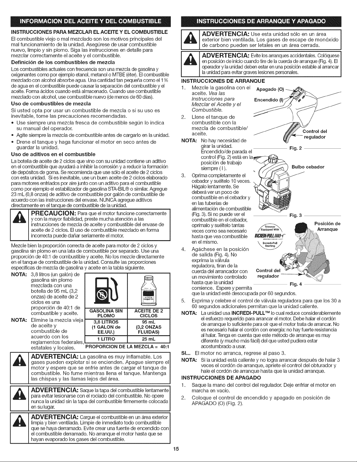
INSTRUCCIONES DE ARRANQUE
1. Mezcle la gasolina con el
aceite. Vea las
Instrucciones para
Mezclar el Aceite y el
Combustible.
2.
Llene el tanque de
combustible con la
mezcla de combustible/
aceite.
No hay necesidad de
girar la unidad.
Encendido/de parada el
control (Fig.2) estAen la
posici6n de trabajo
siempre (I). , (
3. Optima completamente el
k
cebador y sueltelo 10 veces.
Hagalo lentamente. Se
debera ver un poco de
combustible en el cebador y
en las tuber{as de
alimentaci6n de combustible
(Fig.3). Si no puede ver el
combustible en el cebador,
oprfmalo y sueltelo tantas
veces como sea necesario
hasta que vea combustible
en el mismo.
NOTA:
Apagado (O)
Encendido
Control del
ulador
Fig. 2
Bulbo cebador
Fig. 3
Posici6n de
Arranque
2. Coloque el control de encendido y apagado en posici6n de
APAGABO (O)(Fig. 2).
1. Saque la mano del control del regulador. Deje enfriar el motor en
marcha en vacio.
4. Agachese en la posici6n
de salida (Fig.4). No
exprima la valvula
reguladora, tiran de la
cuerda del arrancador con Control del
un movimiento controlado regulador --
hasta que la unidad Fig. 4
comience. Esperey permita
que la unidad este desocupada pot 60 segundos.
5. Exprima y celebre el control de valvula reguladora para que los 30 a
60 segundos adicionales permitan que la unidad caliente.
NOTA: La unidad usa INCREBI-PULL TM Io cual reduce considerablemente
el esfuerzo requerido para arrancar el motor. Debe halar el cord6n
de arranque Io suficiente para oir que el motor trata de arrancar. No
es necesario halar el cord6n con energia:no hay fuerte resistencia
al halar. Tengaen cuenta que este metodo de arranque es muy
diferente (y mucho mas facil)del que usted pudiera estar
acostumbrado a usar.
SL. El motor no arranca, regrese al paso 3.
NOTA: Si la unidad esta caliente y no Iogra arrancar despu6s de halar 3
veces el cord6n de arranque, apriete el control del obturador y
hale el cord6n de arranque hasta que la unidad arranque.
INSTRUCCIONES DE APAGADO
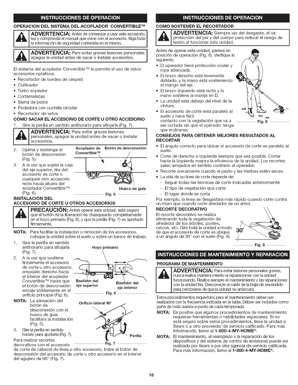
OPERACIONDEL SISTEMA DEL ACOPLADOR CONVERTIBLE TM
_ ADVERTENCIA: Antes de comenzar a usar este accesorio, I
lea y comprenda el manual que viene con el accesorio. Siga toda I
[a informaci6n de seguridad contenida en el mismo. J
ADVERTENOIA: Para evitar graves lesiones personales_[
apague la unidad antes de sacar o instalar accesorios. J
El sistema del acoplador Convertible TM le permite el uso de estos
accesorios optativos.
• Recortador de bordes de cesped
Cultivador
Turbo soplador
Cortamalezas
Sierra de poste
Podadora con cuchilla circular
Recortador de setos
COMO SACAR EL ACCESORIO DE CORTE U OTRO ACCESORIO
1. Gire la perilla en sentido antihorario para aflojarla (Fig. 7).
_1 ADVERTENOIA: Para evitar graves lesiones
I persona.les, apague la unidad antes de sacar o instalar
L===._ accesor os.
J
2. Opimaysostenga el
bot6n de desconexi6n
(Fig. 5).
3. A la vez que sujeta la caja
del eje superior, tire del
accesorio de corte o
cualquier otto accesorio
recto hacia afuera del
acoplador Convertible TM
(Fig. 6).
INSTALACION DEL
Acoplador de Bot6n de desconexi6n
Convert,bie'_ __
Hueeo de gun
Fig. 5
ACCESORIO DE CORTE U OTROS ACCESORIOS
_ RECAUCION: Antes operar esta unidad, est,. seguro
que el bot6n de la liberaci6n es chasqueado completamente
en el hoyo primario (Fig. 6), y que la perilla (Fig. 7) es apretado
firmemente.
NOTA: Para facilitar la instalaci6n o remoci6n de los accesorios,
coloque la unidad sobre el suelo o sobre un banco de trabajo.
1. Gire la perilla en sentido
antihorario para aflojarla Hoyo primario
/Fig7/
2. A la vez que sostiene
firmemente el accesorio
de corte u otro accesorio, _ _1 _x-_l o _h--'_
empQjelo derecho hacia __-_,"
el interior del acoplador
Convertible TM hasta que Bastidor del Bastidor del
el bot6n de desconexi6n eje superior eje inferior
encaje s61idamente en el
orificio principal (Fig. 6). Fig. 6
NOTA: La alineaci6n del
bot6n de Orificio lateral 90°
desconexi6n con el _, J "_ _.
hueco de guia
facilitara la instalaci6n
(Fig. 5).
3. Girela periila en sentido
horatio para ajustarla (Fig.7). riila
Para realizar recortes
decorativos con el accesorio Fig. 7
de corte de cabezal de linea u otto accesorio, trabe el bot6n de
desconexi6n del accesorio de corte u otro accesorio en el interior
del agujero de 90° (Fig. 7).
COMO SOSTENER EL RECORTADOR
[ _ [ ADVERTENOIA: Siempre ojo del desgaste, el oir,
protecci6n del pie y del cuerpo para reducir el riesgo de
lesi6n al funcionar esta unidad.
Antes de operar esta unidad, p_.rese en
posici6n de operaci6n (Fig. 8). Verifique Io
siguiente:
El operador tiene protecci6n ocular y
ropa adecuada.
El brazo derecho esta levemente
doblado, y la mano esta sosteniendo
el mango del eje.
El brazo izquierdo est,. recto y la
mano sostiene la manija en D.
La unidad esta debajo del nivel de la
cintura.
El accesorio de corte esta. paralelo al
suelo y hace fb.cil
contacto con la vegetaci6n que va a
ser cortada sin que el operador tenga
que inclinarse.
CONSEJOS PARA OBTENER MEJORES RESULTADOS AL
RECORTAR
El angulo correcto para ubicar el accesorio de corte es paralelo al
suelo.
Corte de derecha a izquierda siempre que sea posible. Cortar
hacia la izquierda mejora la eficiencia de la unidad. Los recortes
salen arrojados en sentido contrario al operador.
Recorte Onicamente cuando el pasto y las hierbas esten secas.
La vida de su [[nea de corte depende de:
Seguir todas las tecnicas de corte indicadas anteriormente
El tipo de vegetaci6n que corte
El lugar donde se corta
Por ejemplo, la linea se desgastara mas rapido cuando corte contra
un muro que cuando corte alrededor de un arbol.
RECORTE DECORATIVO
El recorte decorativo se realiza
eliminando toda la vegetaci6n de
alrededor de los _.rboles, postes,
cercos, etc. Gire toda la unidad a modo
de que el accesorio de corte se ubique
a un a.ngulo de 30° con el suelo (Fig. 9).
Fig. 9
PROGRAMA DE MANTENIMIENTO
_ DVERTENCIA: Para evitar lesionespersonales graves,
nunca realice manteni-miento ni reparaciones con la unidad
funcionando. Reaiicesiempre el mantenimiento y las reparaciones
con [a unidad fria. Desconecte el cable de la bujia de encendido
para cerciorarse de que la unidad no arrancar&
Estos procedimientos requeridos para el mantenimiento deben ser
realizados con [a frecuencia indicada en latabla. Deben ser incluidos como
parte de toda puesta a punto de cada temporada.
NOTA: Es posible que algunos procedimientos de mantenimiento
requieran herramientas o habilidades especiales. Si no
est,. seguro sobre estos procedimientos, Ileve la unidad a
Sears o a otto proveedor de servicio calificado. Para mas
informaci6n, Ilame al 1-800-4-MY-HOME ®.
NOTA: El mantenimiento, el reemplazo o la reparaci6n de los
dispositivos y del sistema de control de emisiones puede ser
realizado por Sears o por otra agencia de servicio calificada.
Para mas informaci6n, Ilame al 1-800-4-MY-HOME ®.
16
AfindegarantizarelrendimientomAximodesumotor,pudieraser
necesarialainspecci6ndelalumbreradeescapedelmotordespuesde50
horasdeoperaci6n.Siustednotap@didadeRPM,unrendimiento
insuficienteounafaltageneraldeaceleraci6n,pudierarequerirseeste
servicio.Siustedconsideraquesumotornecesitaestainspecci6n,
consulteconSearsuotraagenciadeserviciocalificada.Paramb,s
informaci6n,Ilameal1=800-4=MY-HOME®.NOtratederealizareste
procesoustedmismoyaquepudierada_arelmotorcomoresultadode
contaminantespresentesenelprocesodelimpiezadelalumbrera.
FRECUENCIA MANTENIMIENTO CONSULTE
REQUERIDO
Antes de Uene el tanque de combustible p. 17
arrancar el motor con la mezcla correcta de aceite
y combustible
Cada 10 horass Limpie y vuelva a aceitar el p. 19
filtro de aire
Cada 25 horass Examine el parachispas y limpielo p. 20
Inspeccione la condici6n y la p. 20
separaci6n de la bujia de
encendido
Cada 50 horas Inspeccione si la lumbrera de p. 20
escape y la rejilla del
parachispas estb,n tupidas u
obstruidas para garantizar los
niveles maximos de rendimiento
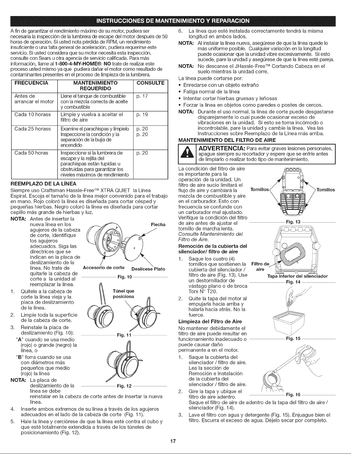
REEMPLAZO DE LA LJNEA
Siempre uso Craftsman Hassle-Free TM XTRA QUIET la Linea
Espiral. Escoja el tama_o de la linea mejor convenido para el trabajo
en mano. Rojo color6 la linea es dise_ada para cortar cesped y
peque_as hierbas. Negro color6 la linea es dise_ada para cortar
cepillo mas grande de hierbas y luz.
NOTA: Antes de insertar la
nueva linea en los
agujeros de la cabeza
de corte, identifique
los agujeros
adecuados. Siga las
directrices que se
indican en la placa de
deslizamiento de la
linea. No trate de
quitarle la cabeza de
corte a la unidad al
reemplazar la linea. _-_
1. Quitele a la cabeza de /_1 Tenel que
corte la linea vieja y la posieiona
placa de deslizamiento \ H
de la linea. /'_..,_.
%0
2. Limpie toda la superficie
de la cabeza de corte.
3. Reinstale la placa de
deslizamiento (Fig. 10): Fig. 11
"A" cuando se usa medio
(rojo) o grande (negro)la ff{I
linea, o
"B" forra cuando se usa
con diametros mas
peque_os que medio
(rojo) la linea
NOTA: La placa de
deslizamiento de la Fig. 12
linea se debe
Flecha
Deslfcese Plato
Fig. 10
reinstalar en la cabeza de corte antes de insertar la nueva
linea.
4. Inserte ambos extremos de su linea a traves de los agujeros
adecuados en el lado de la cabeza de corte (Fig. 11).
5. Hale la linea y cerci6rese de que la linea este contra el cubo y
que este totalmente extendida a traves de los tQneles de
posicionamiento (Fig. 12).
6. La linea que este instalada correctamente tendra la misma
Iongitud en ambos lados.
NOTA: AI instalar la linea nueva, asegQrese de que la linea quede Io
mas uniforme posible. Cualquier variaci6n en la Iongitud
puede ocasionar que la unidad vibre excesivamente. Si esto
sucede, pare la unidad y asegQrese de que la linea este pareja.
NOTA: No descanse el JHassle-Free TM Cortando Cabeza en el
suelo mientras la unidad corre.
La linea puede cortarse por:
• Enredarse con un objeto extra_o
• Fatiga normal de la linea
• Intentar cortar hierbas gruesas y le_osas
• Forzar la linea en objetos como paredes o postes de cercos.
NOTA: Durante el uso normal, la linea de corte puede desgastarse
disparejamente Io cual puede ocasionar exceso de
vibraciones en la unidad. Si esto se torna inc6modo o
incontrolable, pare la unidad y cambie la linea. Vea las
Instrucciones sobre Reemplazo de la Linea mas arriba.
MANTENIMIENTO DEL FILTRO DE AIRE
_ DVERTENCIA: Para evitar graves lesiones personales,
apague siempre su recortador y espere que se enfrie antes
de limpiarlo o realizar todo tipo de mantenimiento.
La condici6n del filtro de aire
es importante para la
operaci6n de la unidad. Un
filtro de aire sucio limitara el
flujo de aire y cambiara la
mezcla de combustible y aire
en el carburador. Esto con
frecuencia se confunde con
un carburador mal ajustado.
Verifique la condici6n del filtro
de aire antes de ajustar el
tornillo de marcha lenta.
Consulte Mantenimiento del
Filtro de Aire.
Remoci6n de la cubierta del
silenciador/filtro de Bite
1.
Saque los cuatro (4)
tornillos que sostienen la
cubierta del silenciador /
filtro de aire (Fig. 13). Use
un destornillador de
vastago piano o de broca
Torx N ° T20.
TorniUos,
Tornillos
Fig. 13
Tapa interior del silenciador
Fig. 14
2. Quite la tapa del motor al
empujarla hacia arriba y
halarla hacia atras. No la
fuerce.
Limpieza del Filtro de Aire
No mantener debidamente el
filtro de aire puede resultar en
funcionamiento inadecuado o
puede causar da_o
permanente a en el motor.
1. Saque la cubierta del
silenciador / filtro de aire.
Lea la secci6n de
Remoci6n e Instalaci6n
de la cubierta del
silenciador / filtro de aire.
Fig. 15
2. Gire la tapa y ubique el
filtro de aire adentro. Fig. 16
Saque el filtro de aire de adentro de la tapa del filtro de aire /
silenciador (Fig. 14).
3. Lave el filtro con agua y detergente (Fig. 15). Enjuague bien el
filtro. Escurra el exceso de agua. Dejelo secar por completo.
17
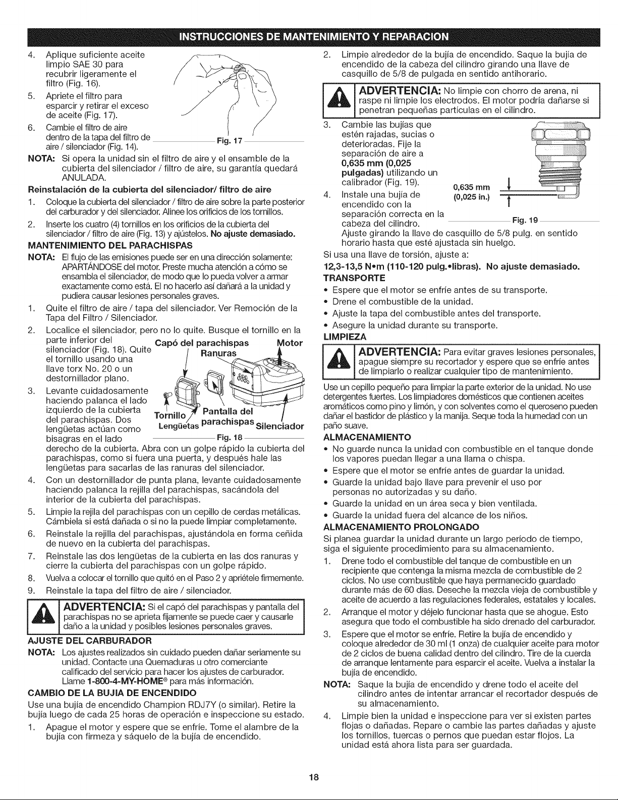
4. Apliquesuficienteaceite
limpioSAE30para
recubrirligeramenteel
filtro(Fig.16).
5. Aprieteelfiltropara
esparciryretirarelexceso
deaceite(Fig.17).
6. Cambieelfiltrodeaire
dentrodelatapadelfiltrode Fig. 17
aire / silenciador (Fig. 14).
NOTA: Si opera la unidad sin el filtro de aire y el ensamble de la
cubierta del silenciador / filtro de aire, su garantia quedara
AN ULADA.
Reinstalaci6n de la cubierta del silenciador/filtro de aire
1. Coloque la cubierta del silenciador / filtro de airesobre la parte posterior
del carburador y del silenciador.Alinee los orificios de los tornillos.
2. Inserte los cuatro (4)tornillos en losorificios de la cubierta del
silenciador / filtro de aire (Fig. 13)y ajOstelos. No ajuste demasiado.
MANTENIMIENTO DEL PARAOHISPAS
NOTA: El flujo de las emisiones puede ser en una direcci6n solamente:
APARTANDOSEdel motor. Preste mucha atenci6n a c6mo se
ensambla el silenciador, de modo que Io pueda volver a armar
exactamente como estA. El no hacerlo ad daSarAa la unidad y
pudiera causar lesiones personales graves.
1. Quite el filtro de aire / tapa del silenciador. Ver Remoci6n de la
Tapa del Filtro / Silenciador.
2. Localice el silenciador, pero no Io quite. Busque el tornillo en la
3.
parte inferior del
silenciador (Fig. 18). Quite
el tornillo usando una
Ilave torx No. 20 o un
destornillador piano.
Levante cuidadosamente
haciendo palanca el lado
izquierdo de la cubierta
del parachispas. Dos
lengQetas actOan como
bisagras en el lado
Cap6 del parachispas Motor
Lengaetas parachlspas Silenciador
Fig. 18
derecho de la cubierta. Abra con un golpe rapido la cubierta del
parachispas, como si fuera una puerta, y despues hale las
lengQetas para sacarlas de las ranuras del silenciador.
4. Con un destornillador de punta plana, levante cuidadosamente
haciendo palanca la rejilla del parachispas, sacandola del
interior de la cubierta del parachispas.
5. Limpie la rejila del parachispas con un cepillo de cerdas metalicas.
Cambiela siesta dadada o si no la puede limpiar completamente.
6. Reinstale la rejilla del parachispas, ajustandola en forma ce5ida
de nuevo en la cubierta del parachispas.
7. Reinstale las dos lengQetas de la cubierta en las dos ranuras y
cierre la cubierta del parachispas con un golpe rapido.
8. Vuelvaa colocar el tornillo que quit6 en el Paso 2 y aprietele firmemente.
9. Reinstale la tapa del filtro de aire / silenciador.
paracHspas no se aprieta fijamente se puede caer y causade
dano a la unidad y posibles lesiones personales graves.
AJUSTE DEL CARBURADOR
NOTA: Los ajustes realizados sin cuidado pueden danar seriamente su
unidad. Contacte una Quemaduras u otro comerciante
calificado del servicio para hacer los ajustes de carburador.
Llame 1-800-4-MY-HOME ® para mAs informaci6n.
CAMBIO DE LA BUJIA DE ENCENDIDO
Use una bujia de encendido Champion RDJ7Y (o similar). Retire la
bujia luego de cada 25 horas de operaci6n e inspeccione su estado.
1. Apague el motor y espere que se enfrie. Tome el alambre de la
bujia con firmeza y saquelo de la bujia de encendido.
2. Limpie alrededor de la bujia de encendido. Saque la bujia de
encendido de la cabeza del cilindro girando una Ilave de
casquillo de 5/8 de pulgada en sentido antihorario.
_ ADVERTENCIA: No limpie con chorro de arena, ni
raspe ni limpie los electrodos. El motor podria da5arse si
penetran peque5as particulas en el cilindro.
3. Cambie las bujias que
esten rajadas, sucias o
deterioradas. Fije la
separaci6n de aire a
0,635 man (0,025
pulgadas) utilizando un
calibrador (Fig. 19). 0,635 mrn
4. Instale una bujia de (0,025 in.)
encendido con la
separaci6n correcta en la
cabeza del cilindro. Fig. 19
Ajuste girando la Ilave de casquillo de 5/8 pulg. en sentido
horario hasta que este ajustada sin huelgo.
Si usa una Ilave de torsi6n, ajuste a:
12,3-13,5 Noan (110-120 pulg.olibras}. No ajuste deanasiado.
TRANSPORTE
Espere que el motor se enfrie antes de su transporte.
• Drene el combustible de la unidad.
Ajuste la tapa del combustible antes del transporte.
Asegure la unidad durante su transporte.
LIMPIEZA
ADVERTENClA: Para evitar graves lesiones personales, 1
apague siempre su recortador y espere que se enfrie antes
de limpiarlo o realizar cualquier tipo de mantenimiento.
Use un cepillo pequeSo para limpiar la parte exterior de la unidad. No use
detergentes fuertes. Los limpiadores domesticos que contienen aceites
aromaticos como pino y lim6n, y con solventes como el queroseno pueden
daSar el bastidor de plastico y la manija. Seque toda la humedad con un
paso suave.
ALMACENAMIENTO
= No guarde nunca la unidad con combustible en el tanque donde
los vapores puedan Ilegar a una llama o chispa.
Espere que el motor se enfrie antes de guardar la unidad.
Guarde la unidad bajo Ilave para prevenir el uso por
personas no autorizadas y su dado.
Guarde la unidad en un area seca y bien ventilada.
Guarde la unidad fuera del alcance de los ni5os.
ALMAOENAMIENTO PROLONGADO
Si planea guardar la unidad durante un largo periodo de tiempo,
siga el siguiente procedimiento para su almacenamiento.
1. Drene todo el combustible del tanque de combustible en un
recipiente que contenga la misma mezcla de combustible de 2
ciclos. No use combustible que haya permanecido guardado
durante mas de 60 dias. Deseche la mezcla vieja de combustible y
aceite de acuerdo alas regulaciones federales, estatales y locales.
2. Arranque el motor y dejelo funcionar hasta que se ahogue. Esto
asegura que todo el combustible ha sido drenado del carburador.
3. Espere que el motor se enfrie. Retire la bujia de encendido y
coloque alrededor de 30 ml (1 onza) de cualquier aceite para motor
de 2 ciclos de buena calidad dentro del cilindro. Tire de la cuerda
de arranque lentamente para esparcir el aceite. Vuelva a instalar la
bujia de encendido.
NOTA: Saque la bujia de encendido y drene todo el aceite del
cilindro antes de intentar arrancar el recortador despues de
su almacenamiento.
4.
Limpie bien la unidad e inspeccione para vet si existen partes
flojas o da_adas. Repare o cambie las partes da_adas y ajuste
los tornillos, tuercas o pernos que puedan estar flojos. La
unidad esta ahora lista para ser guardada.
18
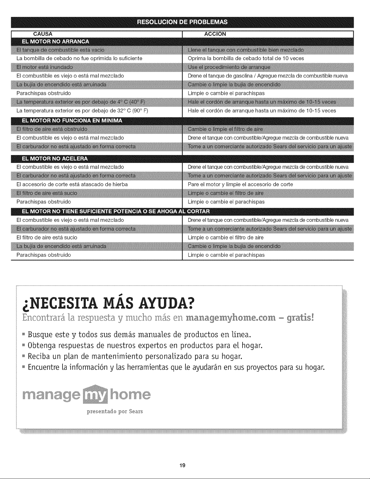
CAUSA
LabombilladecebadonofueoprimidaIosuficiente
Elcombustibleesviejooestamalmezclado
Parachispasobstruido
Latemperaturaexteriorespordebajode32°C(90° F)
Elcombustibleesviejooestamalmezclado
ACCION
Oprima la bombilla de cebado total de 10 veces
Drene el tanque de gasolina / Agregue mezcla de combustible nueva
Limpie o cambie el parachispas
Hale el cord6n de arranque hasta un maximo de 10-15 veces
Drene el tanque con combustible/Agregue mezcla de combustible nueva
El combustible es viejo o esta mal mezclado
El accesorio de corte esta atascado de hierba
Parachispas obstruido
Drene el tanque con combustible/Agregue mezcla de combustible nueva
Pare el motor y limpie el accesorio de corte
Limpie o cambie el parachispas
El combustible es viejo o esta mal mezclado
El filtro de aire esta sucio
Parachispas obstruido
Drene el tanque con combustible/Agregue mezcla de combustible nueva
Limpie o cambie el filtro de aire
Limpie o cambie el parachispas
£SITA AYUDA?
Encontrar_ _a respuesta y mucho m_ en managemyhomeocOm - gratis!
o Busque este y todos sus demos manua[es de productos en [fnea.
o 0btenga respuestas de nuestros expertos en productos para e[ hogar.
o Redba un p[an de mantenimiento persona[izado para su hogar.
o Encuentre [a informad6n y [as herramientas que [e ayudar_n en sus proyectos para su hogar.
presentado [_or Sears
19
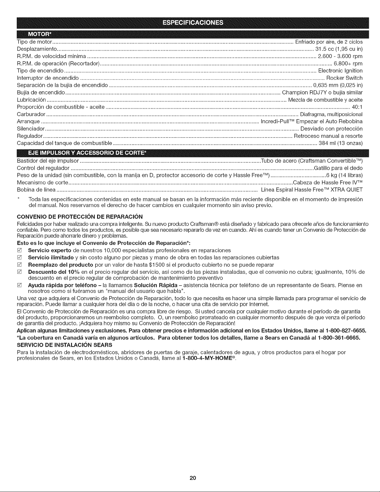
Tipodemotor............................................................................................................................................................Enfriadoporaire,de2ciclos
Desplazamiento......................................................................................................................................................................31.5cc(1,95cuin)
R.RM.develocidadminima....................................................................................................................................................2.600- 3.600rpm
R.RM.deoperaci6n(Recortador)......................................................................................................................................................6.800+rpm
Tipodeencendido...................................................................................................................................................................ElectronicIgnition
Interruptordeencendido..............................................................................................................................................................RockerSwitch
Separaci6ndelabujiadeencendido...................................................................................................................................0,635mm(0,025in)
Bujiadeencendido...........................................................................................................................................ChampionRDJ7Yobujiasimilar
Lubricaci6n...........................................................................................................................................................Mezcladecombustibleyaceite
Proporci6ndecombustible- aceite..............................................................................................................................................................40:1
Carburador...................................................................................................................................................................Diafragma,multiposicional
Arranque.............................................................................................................................................Incredi-PullTM Empezar el Auto Rebobina
Silenciador .................................................................................................................................................................... Desviado con protecci6n
Regulador ................................................................................................................................................................. Retroceso manual a resorte
Capacidad del tanque de combustible .................................................................................................................................... 384 ml (13 onzas)
Bastidor del eje impulsor ..................................................................................................................... Tubo de acero (Craftsman Convertible TM)
Control del regulador ............................................................................................................................................................. Gatillo para el dedo
Peso de la unidad (sin combustible, con la manija en D, protector accesorio de corte y Hassle Free TM) .................................... 6 kg (14 libras)
Mecanismo de corte ................................................................................................................................................. Cabeza de Hassle Free IVTM
Bobina de linea .................................................................................................................................. Linea Espiral Hassle Free TM XTRA QUIET
* Toda las especificaciones contenidas en este manual se basan en la informaci6n mAs reciente disponible en el momento de impresi6n
del manual. Nos reservamos el derecho de hacer cambios en cualquier momento sin aviso previo.
CONVENIO DE PROTECCION DE REPARACION
Felicidades por haber realizado una compra inteligente.Su nuevo producto Craftsman® est#,dise_ado y fabricado para ofrecerle anos de funcionamiento
confiable. Pero como todos los productos, es posible que sea necesario repararlo de vez en cuando. Ahi es cuando tener un Convenio de Proteccbn de
Reparacbn puede ahorrarle dinero y problemas.
Esto es Io que incluye el Convenio de Protecci6n de Reparaci6n*:
[] Servicio experto de nuestros 10,000 especialistas profesionales en reparaciones
[] Servicio ilimitado y sin costo alguno por piezas y mano de obra en todas las reparaciones cubiertas
[] Reemplazo del producto por un valor de hasta $1500 si el producto cubierto no se puede reparar
[] Descuento de110% en el precio regular del servicio, asi como de las piezas instaladas, que el convenio no cubra; igualmente, 10% de
descuento en el precio regular de comprobaci6n de mantenimiento preventivo
[] Ayuda rApida pot tel_fono - la Ilamamos Soluci6n RApida - asistencia tecnica por telefono de un representante de Sears. Piense en
nosotros como si fueramos un "manual del usuario que habla".
Una vez que adquiera el Convenio de Protecci6n de Reparaci6n, todo Io que necesita es hacer una simple Ilamada para programar el servicio de
reparaci6n. Puede Ilamar a cualquier hora del dia o de la noche, o hacer una cita de servicio por Internet.
El Convenio de Protecci6n de Reparaci6n es una compra libre de riesgo. Si usted cancela por cualquier motivo durante el periodo de garantia
del producto, proporcionaremos un reembolso completo. O, un reembolso prorrateado en cualquier momento despues de que venza el periodo
de garantia del producto, iAdquiera hoy mismo su Convenio de Protecci6n de Reparaci6n!
Aplican algunas limitaciones y exclusiones. Para obtener precios e informaci6n adicional en los Estados Unidos, llame al 1-800=827=6655.
*La cobertura en Canada varia en algunos articulos. Para obtener todos los detalles, llarne a Sears en Canada al 1-800-361-6665.
SERVIClO DE INSTALACION SEARS
Para la instalaci6n de electrodomesticos, abridores de puertas de garaje, calentadores de agua, y otros productos para el hogar por
profesionales de Sears, en los Estados Unidos o CanadA, Ilame al 1-800-4-MY-HOME ®.
2O

21
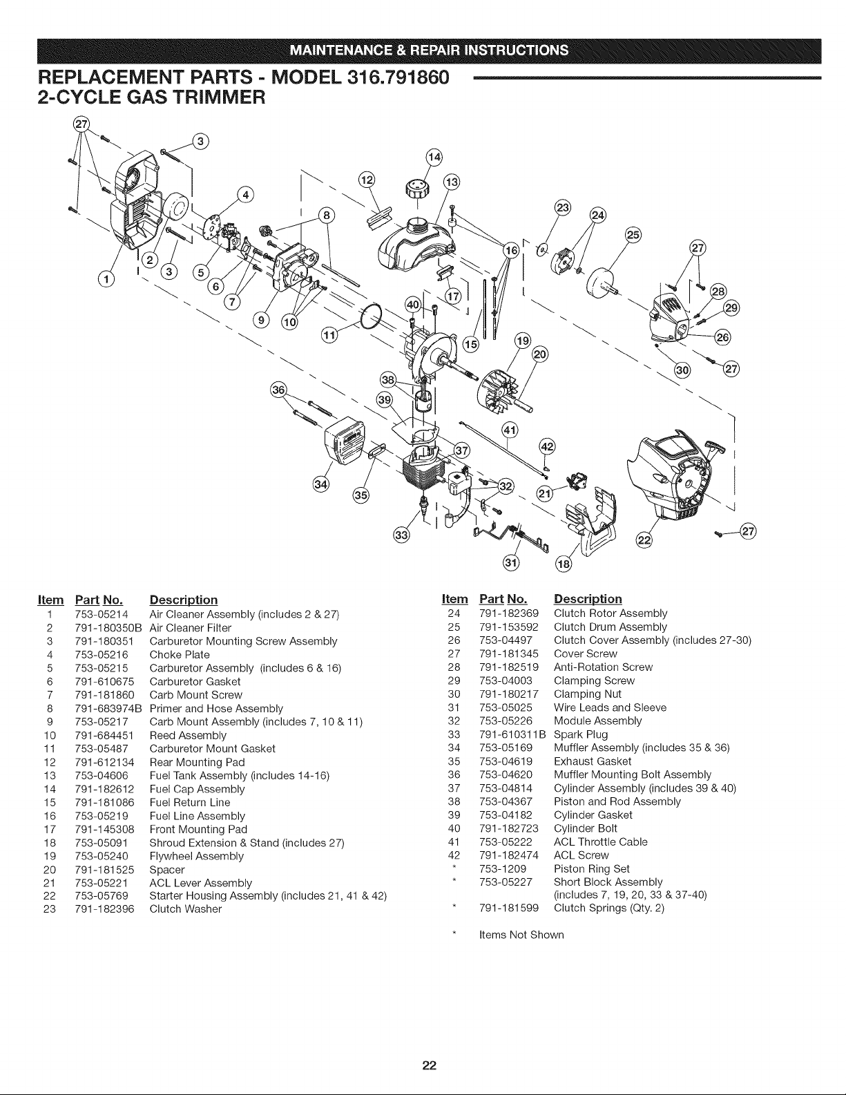
REPLACEMENT PARTS - MODEL 316.791860
2-CYCLE GAS TRIMMER
I
,3
Item Part No.
1 753-05214
2 791-180350B
3 791-180351
4 753-05216
5 753-05215
6 791-610675
7 791-181860
8 791-683974B
9 753-05217
10 791-684451
11 753-05487
12 791-612134
13 753-04606
14 791-182612
15 791-181086
16 753-05219
17 791-145308
18 753-05091
19 753-05240
20 791-181525
21 753-05221
22 753-05769
23 791-182396
Description
Air Cleaner Assembly (includes 2 & 27)
Air Cleaner Filter
Carburetor Mounting Screw Assembly
Choke Plate
Carburetor Assembly (includes 6 & 16)
Carburetor Gasket
Carb Mount Screw
Primer and Hose Assembly
Carb Mount Assembly (includes 7, 10 & 11)
Reed Assembly
Carburetor Mount Gasket
Rear Mounting Pad
Fuel Tank Assembly (includes 14-16)
Fuel Cap Assembly
Fuel Return Line
Fuel Line Assembly
Front Mounting Pad
Shroud Extension & Stand (includes 27)
Flywheel Assembly
Spacer
ACL Lever Assembly
Starter Housing Assembly (includes 21,41 & 42)
Clutch Washer
Item Part No.
24 791-182369
25 791-153592
26 753-04497
27 791-181345
28 791-182519
29 753-04003
30 791-180217
31 753-05025
32 753-05226
33 791-610311B
34 753-05169
35 753-04619
36 753-04620
37 753-04814
38 753-04367
39 753-04182
40 791-182723
41 753-05222
42 791-182474
* 753-1209
* 753-05227
* 791-181599
Description
Clutch Rotor Assembly
Clutch Drum Assembly
Clutch Cover Assembly (includes 27-30)
Cover Screw
Anti-Rotation Screw
Clamping Screw
Clamping Nut
Wire Leads and Sleeve
Module Assembly
Spark Plug
Muffler Assembly (includes 35 & 36)
Exhaust Gasket
Muffler Mounting Bolt Assembly
Cylinder Assembly (includes 39 & 40)
Piston and Rod Assembly
Cylinder Gasket
Cylinder Bolt
ACL Throttle Cable
ACL Screw
Piston Ring Set
Short Block Assembly
(includes 7, 19, 20, 33 & 37-40)
Clutch Springs (Qty. 2)
* Items Not Shown
22
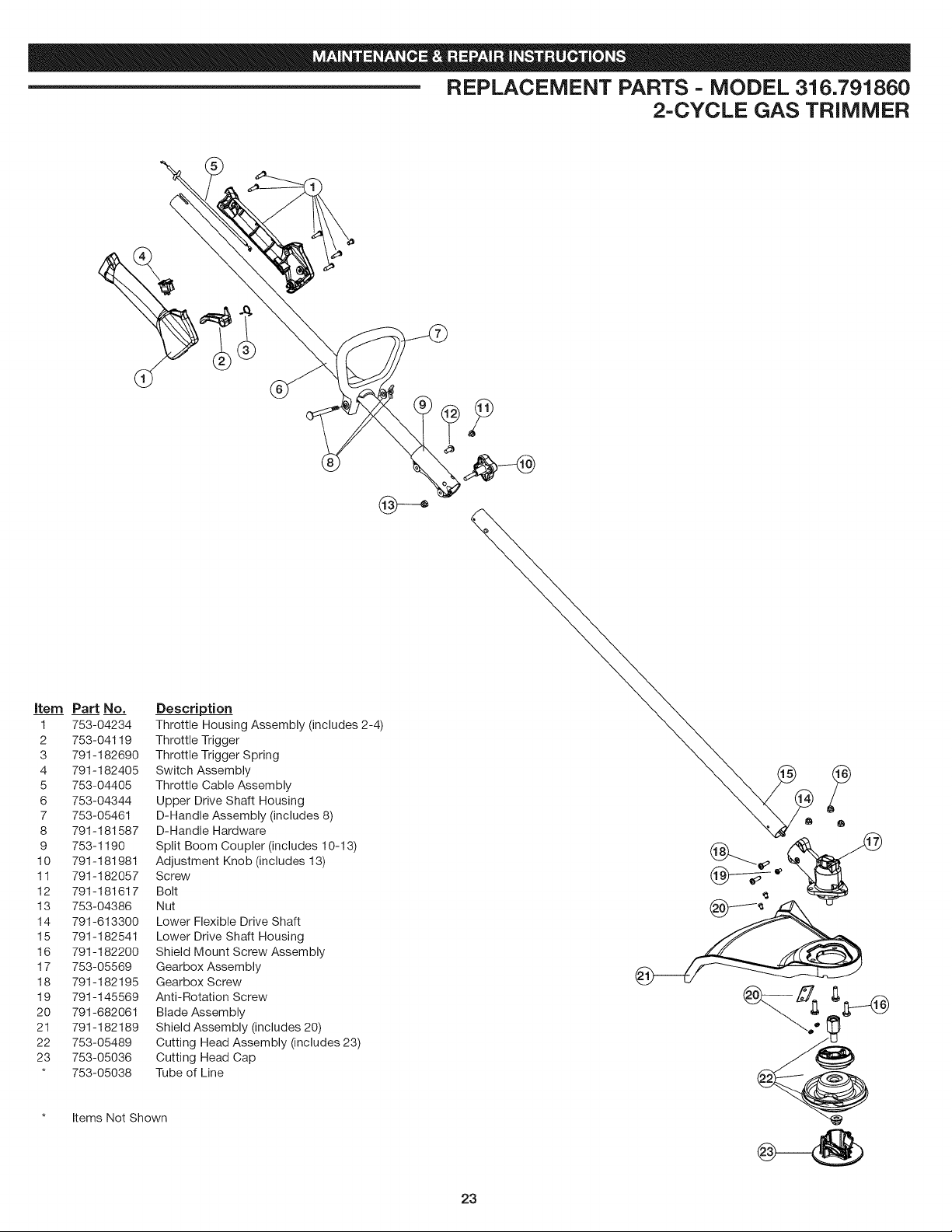
REPLACEMENT PARTS - MODEL 316.791860
2-CYCLE GAS TRIMMER
item Part No.
1 753-04234
2 753-04119
3 791-182690
4 791-182405
5 753-04405
6 753-04344
7 753-05461
8 791-181587
9 753-1190
10 791-181981
11 791-182057
12 791-181617
13 753-04386
14 791-613300
15 791-182541
16 791-182200
17 753-05569
18 791-182195
19 791-145569
20 791-682061
21 791-182189
22 753-05489
23 753-05036
* 753-05038
Description
Throttle Housing Assembly (includes 2-4)
Throttle Trigger
Throttle Trigger Spring
Switch Assembly
Throttle Cable Assembly
Upper Drive Shaft Housing
D-Handle Assembly (includes 8)
D-Handle Hardware
Split Boom Coupler (includes 10-13)
Adjustment Knob (includes 13)
Screw
Bolt
Nut
Lower Flexible Drive Shaft
Lower Drive Shaft Housing
Shield Mount Screw Assembly
Gearbox Assembly
Gearbox Screw
Anti-Rotation Screw
Blade Assembly
Shield Assembly (includes 20)
Cutting Head Assembly (includes 23)
Cutting Head Cap
Tube of Line
Items Not Shown
23

Your Home
For expert troubleshooting and home solutions advice:
@111111@@
www.managernyhome.com
For repair - in your home - of all major brand appliances,
lawn and garden equipment, or heating and cooling systems,
no matter who made it, no matter who sold it!
For the replacement parts, accesspries and
owner's manuals that you need to do-it-yourself.
For Sears professional installation of home appliances
and items like garage door openers and water heaters.
1-800-4-MY=HOME ® ( -8oo-469-466s)
Call anytime, day or night (U.S.A. and Canada)
WW3N.sears.com www.sears.ca
Our Home
For repair of carry-in items like vacuums, lawn equipment,
and electronics, call anytime for the location of your nearest
Sears Parts & Repair Service Center
1-800-488-1222 (U.S.A.)
www.sears.com
1-800-469-4663 (Canada)
www.sears.ca
To purchase a protection agreement on a product serviced by Sears:
1-800-827-6655 (U.S.A.) 1-800-361-6665 (Canada)
Para pedir servicio de reparaci6n Au Canada pour service en fran(_ais:
a domicilio, y para ordenar piezas: 1-800-LE-FOYER Mc
1-800-SU - HOGAR ® (1-800-533-6937)
(1-888-784-6427) www.sears.ca
SM
® Registered Trademark / TMTrademark / Service Mark of Sears Brands, LLC
® Marca Registrada / TMMarca de F&brica / SMMarca de Servicio de Sears Brands, LLC
MCMarque de commerce / MDMarque d6pos6e de Sears Brands, LLC © Sears Brands, LLC