For additional information, refer to . . .
Control Supplement and Gas
Control Parts
for EG/PEG – Natural gas only
for EGH – Natural or Liqueed Petroleum
(Propane) gas
(tankless heater application optional)
EG
PEG
EGH
• Installation
• Startup
• Maintenance
• Parts
Boiler Manual
This manual must only be used by a qualified heating installer/service technician. Before installing, read all instructions,
including this manual, the burner manual and any related supplements. Perform steps in the order given. Failure to
comply could result in severe personal injury, death or substantial property damage.
EG/PEG/EGH
Series 5
Gas-Fired Boilers
Part No. 550-142-905/0319

3DUW1XPEHU
2
Contents
The following defined terms are used throughout this manual to bring attention to the presence of hazards of various risk levels, or
to important information concerning the life of the product.
Indicates presence of hazards that will cause severe personal injury, death or substantial property damage.
Indicates presence of hazards that can cause severe personal injury, death or substantial property damage.
Indicates presence of hazards that will or can cause minor personal injury or property damage.
Indicates special instructions on installation, operation or maintenance that are important but not related to personal
injury or property damage.
+a]ard 'eÀnLtLons . . . . . . . . . . . . . . . . . . . . . . . . . . . . . . . . . . . . . . . . . . 2
5ead tKLs paJe Àrst. . . . . . . . . . . . . . . . . . . . . . . . . . . . . . . . . . . . . . . . . . 4
Codes and CKeFNlLst . . . . . . . . . . . . . . . . . . . . . . . . . . . . . . . . . . . . . . . . . 4
Prepare EoLler loFatLon . . . . . . . . . . . . . . . . . . . . . . . . . . . . . . . . . . . . . . . 5
Prepare tKe EoLler . . . . . . . . . . . . . . . . . . . . . . . . . . . . . . . . . . . . . . . . . . . 9
ConneFt pLpLnJ ³ Zater EoLlers . . . . . . . . . . . . . . . . . . . . . . . . . . . . . . 14
ConneFt pLpLnJ ³ steam EoLlers . . . . . . . . . . . . . . . . . . . . . . . . . . . . . . 17
,nstall EoLler Fontrols . . . . . . . . . . . . . . . . . . . . . . . . . . . . . . . . . . . . . . . 20
ConneFt pLpLnJ ³ tanNless Keater
. . . . . . . . . . . . . . . . . . . . . . . . . . . . . .
21
ConneFt Jas suppl\ pLpLnJ . . . . . . . . . . . . . . . . . . . . . . . . . . . . . . . . . . . 22
ConneFt Àeld ZLrLnJ to EoLler. . . . . . . . . . . . . . . . . . . . . . . . . . . . . . . . . 23
Start-up . . . . . . . . . . . . . . . . . . . . . . . . . . . . . . . . . . . . . . . . . . . . . . . . . . 24
'epartment oI (nerJ\ ² ComplLanFe . . . . . . . . . . . . . . . . . . . . . . . . . . . . 2
SerYLFe and maLntenanFe . . . . . . . . . . . . . . . . . . . . . . . . . . . . . . . . . . . . . 29
+andlLnJ ÀEerJlass and FeramLF ÀEer materLals . . . . . . . . . . . . . . . . . . .
.33
5eplaFement parts ³ (GP(G. . . . . . . . . . . . . . . . . . . . . . . . . . . . . . . . . . 34
5eplaFement parts ³ (G+ . . . . . . . . . . . . . . . . . . . . . . . . . . . . . . . . . . . . 36
'LmensLonal data . . . . . . . . . . . . . . . . . . . . . . . . . . . . . . . . . . . . . . . . . . . 3
5atLnJs . . . . . . . . . . . . . . . . . . . . . . . . . . . . . . . . . . . . . . . . . . . . . . . . . . . 39
Standard and optLonal eTuLpment . . . . . . . . . . . . . . . . . . . . . . . . . . . . . 40
+a]ard deÀnLtLons
EG
&
PEG SERIES 5
s
EGH SERIES 5 GAS-FIRED BOILERS — BOILER MANUAL
3DUW1XPEHU
3
5ead tKLs paJe Àrst
Failure to adhere to the guidelines below can result in severe personal injury, death or substantial property damage.
When servicing boiler —
To avoid electric shock, disconnect all
electrical supplies to the boiler before
performing maintenance.
To avoid severe burns, allow boiler to cool
before performing maintenance.
This boiler contains ceramic fiber and
fiberglass materials. Refer to the WARN-
ING and instructions on page 33.
Boiler operation —
Do not block flow of combustion or ven-
tilation air to boiler.
Should overheating occur or gas supply
fail to shut off, do not turn off or discon-
nect electrical supply to pump. Instead,
shut off the gas supply at a location ex-
ternal to the appliance.
Combustion air —
DO NOT install combustion air intake
where there is a risk of combustion air
contamination.
Boiler water —
Do not use petroleum-based cleaning
or sealing compounds in boiler system.
Gaskets and seals in the system may be
damaged. This can result in substantial
property damage.
DO NOT use “ homemade cures ” or “
boiler patent medicines”. Serious dam-
age to boiler, personnel and/or property
may result.
Continual fresh make-up water will re-
duce boiler life. Mineral buildup in eat
exchanger reduces heat transfer, overheats
the aluminum heat exchanger, and causes
failure. Addition of oxygen carried in by
make-up water can cause internal cor-
rosion. Leaks in boiler or piping must
be repaired at once to prevent make-up
water. Use this boiler ONLY in a closed-
loop system.
Do not add cold water to a hot boiler.
Thermal shock can cause sections to crack.
Freeze protection fluids —
NEVER use automotive or standard
glycol antifreeze. Use only freeze-
protection fluids made for hydronic
systems. Follow all guidelines given
by the antifreeze manufacturer.
Thoroughly clean and flush any re-
placement boiler system that has used
glycol before installing the new boiler
Frozen Water Damage
Hazard
Residences or buildings that are unat-
tended in severely cold weather, boiler
system components failures, power out-
ages, or other electrical system failures
could result in frozen plumbing and water
damage in a matter of hours. For your
protection, take preventative actions such
as having a security system installed that
operates during power outages, senses low
temperature, and initiates an effective ac-
tion. Consult with your boiler contractor
or a home security agency.
If any part of a boiler, burner or its controls has
been sprayed with or submerged under water,
either partially or fully, DO NOT attempt to op-
erate the boiler until the boiler has been either
replaced or completely repaired, inspected, and
you are sure that the boiler and all components
are in good condition and fully reliable.
Otherwise, by operating this boiler, you will
cause a fire or explosion hazard, and an electrical
shock hazard, leading to serious injury, death, or
substantial property damage. See the instructions
at right.
3ALTWATER $AMAGE — The exposure of boiler components to
saltwater can have both immediate and long-term effects. While the
immediate effects of saltwater damage are similar to those of fresh-
water (shorting out of electrical components, washing out of critical
lubricants, etc.), the salt and other contaminants left behind can lead
to longer term issues after the water is gone due to the conductive
and corrosive nature of the salt residue. Therefore, Weil-McLain
equipment contaminated with saltwater or polluted water will no
longer be covered under warranty and should be replaced.
%LECTRICAL $AMAGE — If any ELECTRICAL COMPONENT or WIRING
came into contact with water, or was suspected to have come into
contact with water, replace the boiler with a new Weil-McLain boiler.
)NSTALLER— Read all instructions, including this
manual and all other information shipped with the
boiler, before installing. Perform steps in the order
given.
5SER— This manual is for use only by a qualified
heating installer/service technician. Refer to User’s
Information Manual for your reference.
5SER — Have this boiler serviced/inspected by a
qualified service technician, at least annually.
Failure to comply with the above could result in severe
personal injury, death or substantial property damage.
Improper installation, adjustment, alteration, ser-
vice or maintenance can cause property damage,
personal injury, exposure to hazardous materials,
or loss of life. Installation and service must be
performed by a qualified installer, service agency
or the gas supplier who must read and follow the
supplied instructions before installing, servicing or
removing this boiler. This boiler contains possibly
carcinogenic, to humans.
Write in the CP number in the space provided on the
)NSTALLATIONAND3ERVICE#ERTIlCATE on page 27, if
not already shown.
When calling or writing about the boiler— Please
have the boiler model number from the boiler rating
label and the CP number from the boiler jacket.
Consider piping and installation when determining
boiler location.
Any claims for damage or shortage in shipment
must be filed immediately against the transportation
company by the consignee.
EG and EGH boilers for tankless or storage heater
application are available only on special order as
factory-installed optional equipment. Tankless
heater cannot be added to standard block assem-
bly. Block assembly must be ordered with heater
openings. Standard boilers cannot be adapted for
heater use.
EG
&
PEG SERIES 5
s
EGH SERIES 5 GAS-FIRED BOILERS — BOILER MANUAL

3DUW1XPEHU
4
Installation must follow these codes:
s Local, state, provincial, and national codes, laws, regulations and ordinances.
s National Fuel Gas Code, ANSI Z223.1/NFPA 54 - latest edition.
s National Electrical Code, ANSI/NFPA 70 – latest edition, and/or the Canadian Electrical Code
Part I, CSA C22.1, Electrical Code.
s Canadian installations must comply with the Natural Gas and Propane Installation Code,
CAN/CSA B149.1 or B149.2 Installation Codes.
s Where required by the authority having jurisdiction, the installation must conform to the
Standard for Controls and Safety Devices for Automatically Fired Boilers, ANSI/ASME
CSD1.
The equipment shall be installed in accordance with those installation regulations in force in
the local area where the installation is to be made. These shall be carefully followed in all cases.
Authorities having jurisdiction shall be consulted before installations are made.
Commonwealth of Massachusetts
When the boiler is installed within the Commonwealth of Massachusetts:
s 4HISPRODUCTMUSTBEINSTALLEDBYALICENSEDPLUMBER
s )FANTIFREEZEISUSEDAREDUCEDPRESSUREBACKmOWPREVENTERDEVICESHALLBEUSED
Certification
Safe operating and other performance criteria were met with the gas manifold
and control assembly provided on boiler when boiler underwent tests specified
in ANSI Z21.13 - latest edition.
Before locating the boiler:
❏ Check for nearby connection to:
s6ENTINGCONNECTIONS
s'ASSUPPLYPIPING
s%LECTRICALPOWER
❏ Check area around boiler. Remove any combustible materials, gasoline and other flammable
liquids.
Failure to keep boiler area clear and free of combustible materials, gasoline and
other flammable liquids and vapors can result in severe personal injury, death or
substantial property damage.
❏ Boiler must be installed so that gas control system components are protected from dripping
or spraying water or rain during operation or service.
❏ If new boiler will replace existing boiler, check for and correct system problems, such as:
s3YSTEMLEAKSCAUSINGOXYGENCORROSIONORSECTIONCRACKSFROMHARDWATERDEPOSITS
Glycol — potential fire hazard —
All glycol is flammable when exposed to high temperatures. If glycol is allowed to accumulate
in or around the boiler or any other potential ignition source, a fire can develop. In order to
prevent potential severe personal injury, death or substantial property damage from fire and/
or structural damage:
s .EVERSTOREGLYCOLOFANYKINDNEARTHEBOILERORANYPOTENTIALIGNITIONSOURCE
s -ONITORANDINSPECTTHESYSTEMANDBOILERREGULARLYFORLEAKAGE2EPAIRANYLEAKSIMMEDI-
ately to prevent possible accumulation of glycol.
Codes CKeFNlLst
EG
&
PEG SERIES 5
s
EGH SERIES 5 GAS-FIRED BOILERS — BOILER MANUAL

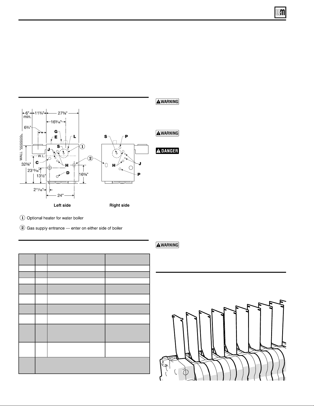
&IGUREAlcove installation (EG & PEG only)
EGH installations
1. See Table 1 for clearances to boiler and system compo-
nents.
2. Provide the clearances for service and clearance to com-
bustible materials as listed on this page.
3. Install in a space that is large in comparison to the size of
the boiler (see National Fuel Gas Code for details).
3DUW1XPEHU
5
4ABLE EG, PEG & EGH -Service and combustible
materials clearances
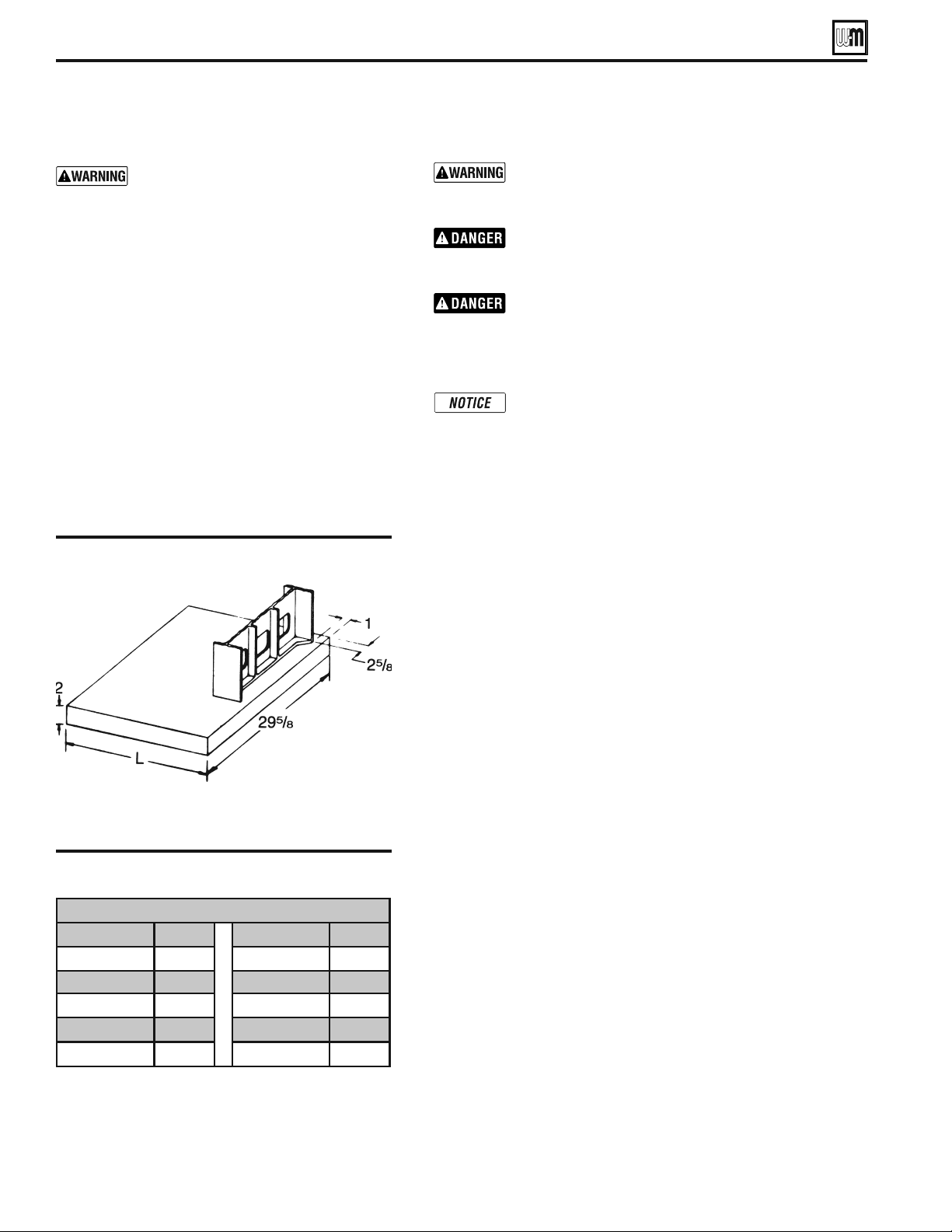
Prepare EoLler loFatLon
Recommended Service clearances
1. Provide minimum clearances for cleaning and servicing
the boiler and for access to controls and components as
listed in the table at right.
2. Provide at least screwdriver clearance to jacket front panel
screws for removal of front panel for inspection and minor
service. If unable to provide at least screwdriver clearance,
install unions and shutoff valves in system so boiler can be
moved for servicing.
Combustible material clearances
General
1. See Table 1 for clearances to boiler and system components.
2. Clearances to Type B vent materials are as specified by the
vent manufacturer.
Alcove (not closet) installations only
%'AND0%'BOILERSARENOTAPPROVEDFOR
CLOSETINSTALLATION
EG and PEG boilers are approved for ALCOVE
installation, with minimum clearances to
combustible surfaces as shown in Table 1. See
Figure 1. The front side must be completely open
— that is, a three-walled room.
%'(BOILERSARENOTAPPROVEDFORALCOVEOR
CLOSETINSTALLATION
EG, PEG & EGH - Clearance for service Minimum
Clearance to boiler jacket
Top IRUFOHDQLQJÀXHZD\V 46”
Front
IRUDFFHVVWRFRQWUROVDQGFRPSRQHQWV 18”
Back 6”
Left side IRUFOHDQLQJDQGVHUYLFLQJ 24”
Right side 6”
Clearance to combustible materials
Minimum
EG & PEG
Minimum
EGH
Clearance to boiler jacket
Top
46” 46”
Front SURYLGHVPHDQVRIDFFHVV
3” 18”
Back
6” 24”
Left side SURYLGHVPHDQVRIDFFHVV
4” 24”
Right side
4” 24”
Clearance to piping and vent components
Water and steam pipes
1/2” 1/2”
Vent pipe (other than Type B vent)
6” 6”
Type B vent piping
Per B vent
PDQXIDFWXUHU
Per B vent
PDQXIDFWXUHU
Vent damper
6” 6”
Residential garage installations
Take the following special precautions when installing the boiler in
a residential garage. If the boiler is located in a residential garage,
per ANSI Z223.1/NFPA 54:
s -OUNTTHEBOILERAMINIMUMOFINCHESABOVETHEmOOROF
the garage to assure the burner and ignition devices will be
NOLESSTHANINCHESABOVETHEmOOR
s ,OCATE OR PROTECT THE BOILERSO IT CANNOTBE DAMAGED BYA
moving vehicle.
EG
&
PEG SERIES 5
s
EGH SERIES 5 GAS-FIRED BOILERS — BOILER MANUAL
4ABLEMinimum foundation size
&IGURE Boiler foundation
3DUW1XPEHU
6
Vent System
Failure to follow all instructions can result in flue gas
spillage and carbon monoxide emissions, causing severe
personal injury or death.
Inspect existing chimney before installing boiler. Failure
to clean or replace perforated pipe or tile lining will cause
severe personal injury or death.
Do not alter boiler draft diverter or place any obstruction
or non-certified vent damper in breeching or vent system.
CSA certification will become void. Flue gas spillage and
carbon monoxide emissions will occur causing severe
personal injury or death.
The following requirements apply when you remove
an existing boiler from a vent system shared with other
appliances. If the new boiler will not use the common
vent, you must test (as described below) each remaining
appliance — operating by itself — to verify that the vent
system operates adequately.
When removing boiler from existing common vent system:
At the time of removal of an existing boiler, the following steps shall
be followed with each appliance remaining connected to the common
venting system placed in operation, while the other appliances remaining
connected to the common venting system are not in operation.
a. Seal any unused openings in the common venting system.
b. Visually inspect the venting system for proper size and horizontal
pitch and determine there is no blockage or restriction, leakage, cor-
rosion or other deficiencies which could cause an unsafe condition.
c. Test vent system — Insofar as is practical, close all building doors and
windows and all doors between the space in which the appliances
remaining connected to the common venting system are located and
other spaces of the building. Turn on clothes dryers and any appli-
ance not connected to the common venting system. Turn on any
exhaust fans, such as range hoods and bathroom exhausts, so they
will operate at maximum speed. Do not operate a summer exhaust
fan. Close fireplace dampers.
d. Place in operation the appliance being inspected. Follow the
op-
erating instructions. Adjust thermostat so appliance will operate
continuously.
e. Test for spillage at draft diverter relief opening after 5 minutes of
main burner operation. Use the flame of a match or candle.
f. After it has been determined that each appliance remaining con-
nected to the common venting system properly vents when tested
as outlined above, return doors, windows, exhaust fans, fireplace
dampers, and any other gas-burning appliance to their previous
conditions of use.
Any improper operation of the common venting system should be cor-
rected so the installation conforms with the National Fuel Gas Code,
ANSI Z223.1/NFPA 54 - latest edition and/or Natural Gas and Propane
Installation Code, CAN/CGA B149 or B149.2, Installation Codes. When
resizing any portion of the common venting system, the common venting
system should be resized to approach the minimum size as determined
using the appropriate tables in the National Fuel Gas Code, ANSI Z223.1/
NFPA 54 - latest edition and/or Natural Gas and Propane Installation
Code, CAN/CSA B149.1 or B149.2, Installation Codes.
Flooring and foundation
Do not install boiler on combustible
flooring or carpeting even if a concrete or
aerated foundation is used. Fire can result,
causing severe personal injury, death or
substantial property damage.
1. See Figure 2. A level concrete or solid brick pad is
required if:
a) There is a possibility of the floor becoming
flooded.
b) Non-level conditions exist.
2. An aerated boiler foundation is recommended if
any of the following conditions exist:
a) Electrical wiring or telephone cables buried in
the concrete floor of the boiler room.
b) Concrete floor is “green.”
c) There is a history of the floor becoming flooded.
d) Water is channeled under the concrete.
1 Prepare EoLler loFatLon (continued)
Boiler Foundation Size - Inches
Boiler No. “L” Boiler No. “L”
EG 30-35 19 EGH 85 40 1/4
EG 40-45 23 1/4 EGH 95 44 1/2
EG 50-55 27 1/2 EGH 105 48 3/4
EG 65 31 3/4 EGH 115 53
EG 75 36 EG 125 57 1/4
EG
&
PEG SERIES 5
s
EGH SERIES 5 GAS-FIRED BOILERS — BOILER MANUAL
3DUW1XPEHU
7
Products to avoid
6SUD\FDQVFRQWDLQLQJFKORURÀXRURFDUERQV
3HUPDQHQWZDYHVROXWLRQV
&KORULQDWHGZD[HVFOHDQHUV
&KORULQHEDVHGVZLPPLQJSRROFKHPLFDOV
&DOFLXPFKORULGHXVHGIRUWKDZLQJ
6RGLXPFKORULGHXVHGIRUZDWHUVRIWHQLQJ
Refrigerant leaks
3DLQWRUYDUQLVKUHPRYHUV
+\GURFKORULFDFLGPXULDWLFDFLG
&HPHQWVDQGJOXHV
$QWLVWDWLFIDEULFVRIWHQHUVXVHGLQFORWKHVGU\HUV
&KORULQHW\SHEOHDFKHVGHWHUJHQWVDQGFOHDQLQJVROYHQWV
IRXQGLQKRXVHKROGODXQGU\URRPV
$GKHVLYHVXVHGWRIDVWHQEXLOGLQJSURGXFWVDQGRWKHUVLPLODU
SURGXFWV
Areas likely to have contaminants
'U\FOHDQLQJODXQGU\DUHDVDQGHVWDEOLVKPHQWV
6ZLPPLQJSRROV
0HWDOIDEULFDWLRQSODQWV
Beauty shops
Refrigeration repair shops
Photo processing plants
$XWRERG\VKRSV
3ODVWLFPDQXIDFWXULQJSODQWV
)XUQLWXUHUH¿QLVKLQJDUHDVDQGHVWDEOLVKPHQWV
1HZEXLOGLQJFRQVWUXFWLRQ
5HPRGHOLQJDUHDV
*DUDJHVZLWKZRUNVKRSV
%XLOGLQJVXQGHUFRQVWUXFWLRQZKHUHDLULVFRQWDPLQDWHGZLWK
particulates)
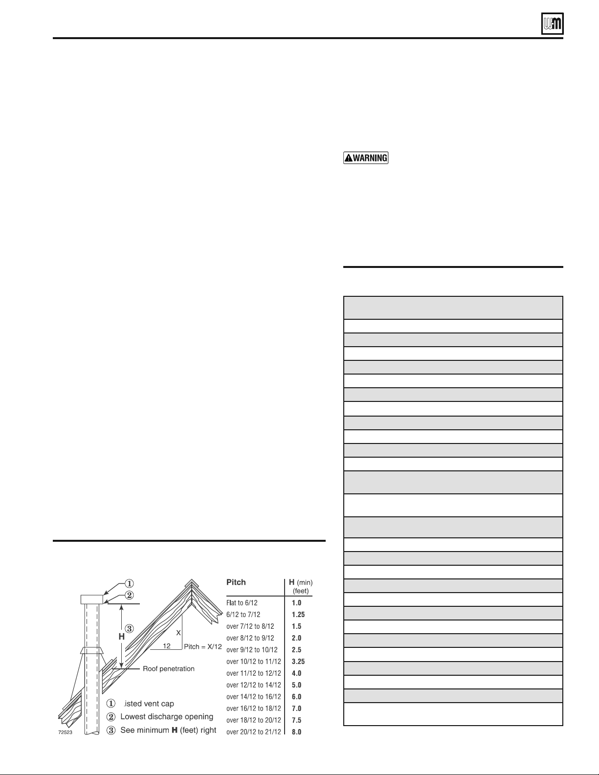
&IGURE Terminations with Type B vent fitted with listed cap,
provided vent is at least 8 feet from any vertical wall or
similar obstruction
Vent System (continued)
Chimney or vent requirements
1. Venting must be installed according to the National Fuel Gas Code,
ANSI Z223.1/NFPA 54–latest edition and applicable building codes.
Canadian installations must comply with Natural Gas and Propane
Installation Code, B149.1 or B149.2 Installation Codes.
3EEh2ATINGSvON PAGE FORMINIMUM CHIMNEY ORVENTSIZES
Chimney or vent termination:
s A chimney, or any vent other than a Type B vent with listed vent
cap, must extend at least 3 feet above the highest point where it
passes through a roof of a building, and at least 2 feet higher than
any portion of a building within a horizontal distance of 10 feet.
s 4YPE"VENTSWITHLISTEDCAPSMAYTERMINATEASIN&IGUREIFNO
CLOSERTHANFEETFROMAVERTICALWALLORSIMILAROBSTRUCTION
s /THERWISE4YPE"VENTSMUSTTERMINATEATLEASTFEETABOVETHE
roof penetration and at least 2 feet higher than any portion of a
building within 10 feet.
s Ensure proper clearance above grade or snowline. Keep vents/air
intake area clear of accumulating snow.
3. A lined chimney is preferred and must be used when required by
local, state, provincial and national codes, laws, regulations and
ordinances. Vitreous tile linings with joints that prevent retention
of moisture and linings made of noncorrosive materials are best.
Advice for flue connections and chimney linings can be obtained
from local gas utility. Type B double-wall metal vent pipe or single-
wall vent pipe may be used as a liner.
4. Cold masonry chimneys, also known as outside chimneys, typically
have one or more walls exposed to outside air. When any atmospheric
gas-fired boiler with automatic vent damper is vented through this
type of chimney, the potential exists for condensation to occur.
Condensation can damage a masonry chimney. The following are
recommended to prevent possible damage.
a. Line chimney with corrosion-resistant metal liner such as AL29-4C®
single-wall stainless steel or B-vent. Size liner per National Fuel Gas
Code ANSI Z223.1/NFPA 54–latest edition.
b. Provide drain trap to remove any condensate.
5. Where two or more gas appliances vent into a common chimney or
vent, equivalent area should be at least equal to area of vent outlet
on largest appliance plus 50 percent of vent outlet area of additional
appliances.
Air contamination
1. Please review the following information on potential
combustion air contamination problems.
2. See Table 3 for products and areas which may cause
contaminated combustion air.
To prevent potential of severe personal injury
or death, check for products or areas listed
below before installing boiler. If any of these
contaminants are found:
s2EMOVECONTAMINANTSPERMANENTLY
— OR —
s)SOLATEBOILERANDPROVIDEOUTSIDECOMBUS-
tion air. See national, provincial or local
codes for further information.
Prepare EoLler loFatLon
4ABLE Contaminants to avoid
EG
&
PEG SERIES 5
s
EGH SERIES 5 GAS-FIRED BOILERS — BOILER MANUAL
3DUW1XPEHU
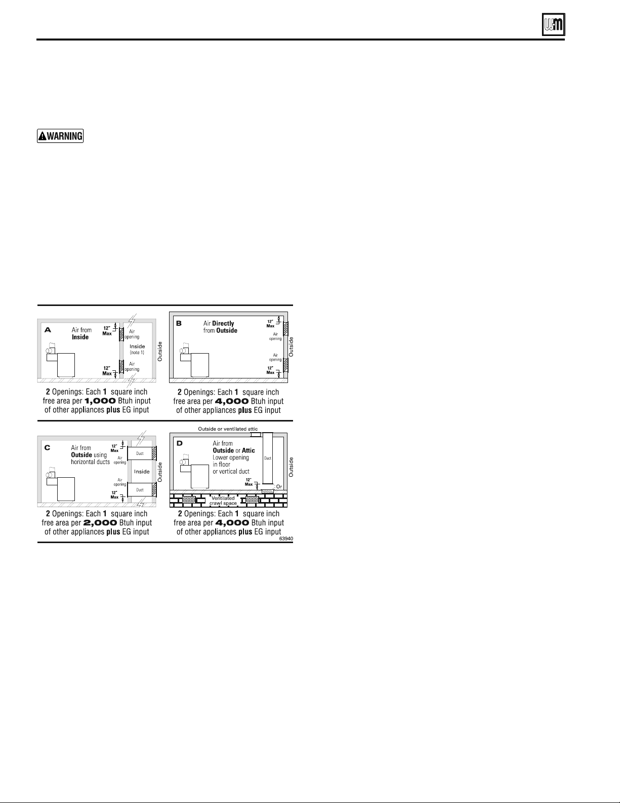
!IROPENINGS
Provide adequate combustion and ventilation air
to assure proper combustion and reduce the risk
of severe personal injury, death or substantial prop-
erty damage caused by flue gas spillage and carbon
monoxide emissions.
Combustion air and ventilation openings must comply with
the National Fuel Gas Code, ANSI Z223.1/NFPA 54 – latest edi-
tion, or applicable local building codes. Canadian installations
must comply with Natural Gas and Propane Installation Code,
B149.1 or B149.2 Installation Codes.
Air opening sizes in the following are given in free area (after
correction for louver obstruction).
Option 1 — Provide (2) openings:
Option 2 — Provide (1) opening:
A single combustion air opening can be used, provided:
s 4HE
opening must commence within 12 inches of the ceiling.
s 4HEBOILERMUSTHAVECLEARANCESOFATLEASTINCHFROMBOTH
sides and back, and 6 inches from the front.
s 4HEOPENINGMUSTCONNECTDIRECTLYTOTHEOUTDOORSORTOA
space that communicates directly to the outdoors.
s 4HEAIRCANBEPROVIDEDTHROUGHADIRECTOPENINGORTHROUGH
a horizontal or vertical duct.
s 4HEFREEAREAOFTHEOPENINGMUSTBEATLEASTEQUALTOTHESUM
of all vent connectors in the space.
s 4HEFREEAREAOFTHEOPENINGMUSTBEATLEASTSQUAREINCH
per 3000 Btu/hr input rating of all equipment located in the
space.
Tight construction — Definition:
Tight construction means (per ANSI Z223.1/NFPA 54):
s 7ALLSANDCEILINGSEXPOSEDTOTHEOUTSIDEATMOSPHEREHAVEA
continuous water vapor retarder with a rating of 1 perm or
less with openings gasketed AND
s Weather-stripping has been added on openable windows and
doors AND
s #AULKINGORSEALANTSAREAPPLIEDTOAREASSUCHASJOINTSAROUND
windows and door frames, between sole plates and floors, be-
tween wall-ceiling joints, between wall panels, at penetrations
for plumbing, electrical, and gas lines, and in other openings.
Tight construction requirements
If building is of tight construction and air is taken from inside
the building, provide two openings in building outside wall, one
within 12 inches of ceiling, the other within 12 inches of the floor.
Each opening must have a minimum free area of 1 square inch
per 1,000 Btuh of all appliances in the building.
Exception
NO combustion air openings are needed when the boiler (and
other appliances) are installed in a space with a volume NO LESS
than 50 cubic feet per 1,000 Btuh of all installed appliances. Sum
the total input of all appliances in MBH (1,000’s of Btuh) and
multiply this number times 50. Building must not be of Tight
construction (see above).
Example: For total input of 100 MBH (100,000 Btuh), minimum
VOLUMEISXCUBICFEET!TACEILINGHEIGHTOFFEET
SPACEMUSTHAVEATLEAST¿SQUAREFEETFEETX
feet, for instance).
Exhaust fans and air movers
The appliance space must never be under a negative pressure.
Always provide air openings sized not only to the dimensions
required for the firing rate of all appliances, but also to handle
the air movement rate of the exhaust fans or air movers using air
from the building or space.
Motorized air dampers
If the air openings are fitted with motorized dampers, electrically
interlock the damper to:
s 0REVENTTHEBOILERFROMlRINGIFTHEDAMPERISNOTFULLYOPEN
s 3HUTTHEBOILERDOWNSHOULDTHEDAMPERCLOSEDURINGBOILER
operation.
To accomplish this interlock, wire an isolated contact (proving the
damper open) in series with the thermostat input to the boiler.
The boiler will not start if this damper is closed, and will shut
down should damper close during operation.
0LACEMENTANDSETUP
Place boiler/crate near position
1. Leave boiler in crate and on pallet until installation site is
ready.
2. Move entire crate and pallet next to selected location.
3. Remove crate. Leave boiler on pallet.
4. Unbolt boiler from pallet.
5. Remove boiler from pallet.
Prepare tKe loFatLon
EG
&
PEG SERIES 5
s
EGH SERIES 5 GAS-FIRED BOILERS — BOILER MANUAL
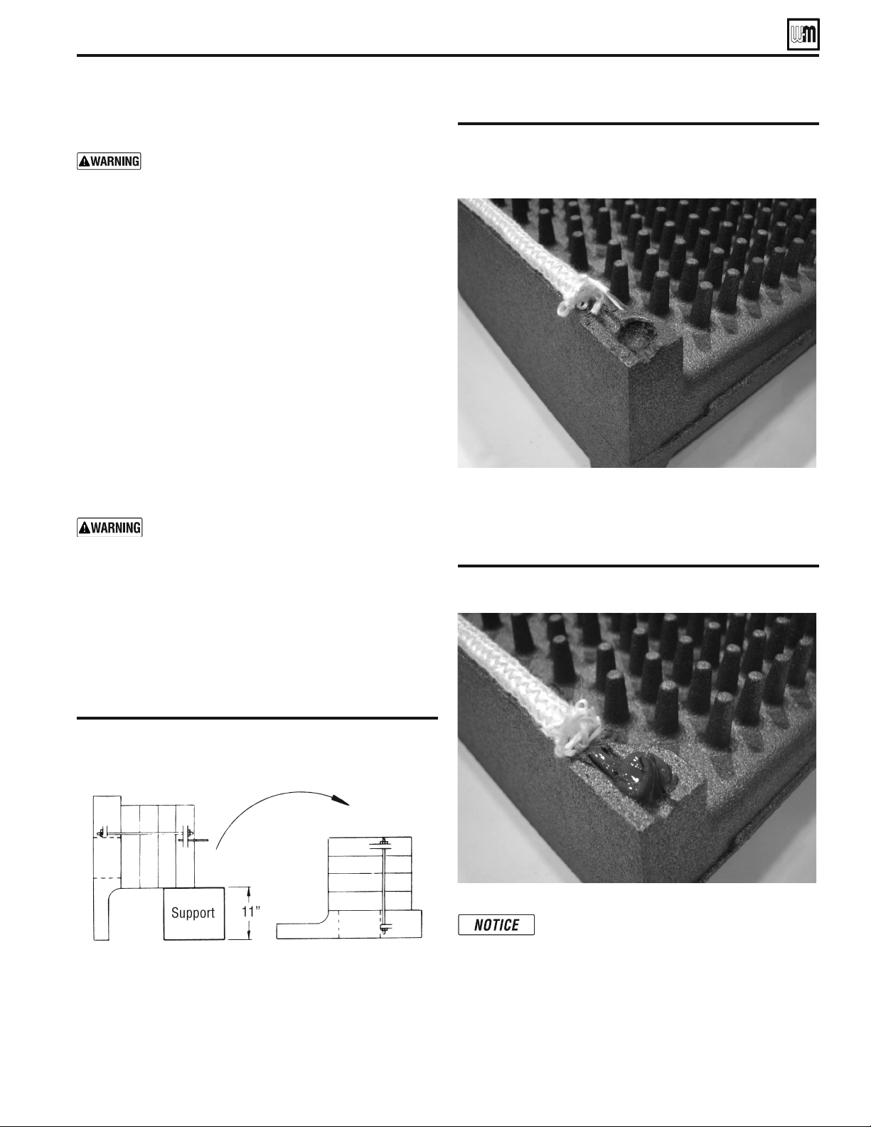
&IGURE Handling split blocks
3DUW1XPEHU
9
Placing the boiler
Block assembly is extremely heavy. Handle with
caution to avoid personal injury.
EGH boilers only —
When an EGH block assembly is taken apart for handling:
1. Put a support under center of block. Support must be
within ½ inch of block bottom.
2. Detach seal replacement kit from the draw rod. Remove
short center draw rods.
3. Tip half blocks on end as shown in Figure 4. Save elas-
tomer sealing ring between sections.
4. Remove the exposed silicone from the socket areas
located in the bottom-front and top-rear corners of the
casting. See Figure 4a. Do not remove the rope seal.
5. After moving half-blocks into desired location,
clean port surfaces with clean, dry rag. Do not use
petroleum-based solvents. Place sealing rings in
recessed ports. Place new silicone in the socket area as
seen in Figure 4b. It is critical to place enough silicone
in this area to reseal the castings.
Do not use petroleum-based cleaning or
sealing compounds in boiler system. Severe
damage to system components can result,
causing substantial property damage.
6. Re-assemble block in reverse order. When drawing sec-
tions together, use 45 ( ± 5 ) ft-lbs torque.
Figure 4a Corner after exposed silicone has
been removed.
Figure 4b Placing of new silicone in the sockets.
Place enough silicone in the socket to
make a seal with the mating surface on the
adjacent casting when assembled.
Prepare tKe EoLler
EG
&
PEG SERIES 5
s
EGH SERIES 5 GAS-FIRED BOILERS — BOILER MANUAL
3DUW1XPEHU
10
Hydrostatic pressure test
Pressure test before attaching gas piping or electrical supply.
1. Plug any necessary boiler tappings or openings.
2. Do not use gauge supplied with boiler for pressure testing.
Install gauge with appropriate range.
3. Fill boiler with water. Vent all air. Test steam boilers between
45 - 55 psi. Test water boilers at 1-1/2 times maximum work-
ing pressure.
Do not leave boiler unattended. A cold water fill could
expand and cause excessive pressure, resulting in severe
personal injury, death or substantial property damage.
4. Verify gauge pressure is maintained. Check for leaks. Repair
if found.
Leaks must be repaired at once. Failure to do so can
cause boiler damage, resulting in substantial property
damage.
Do not use petroleum-based sealing compounds in
boiler system. Severe damage to boiler will result,
causing substantial property damage.
5. Drain boiler and repair leaks if found.
6. Retest boiler after repairing leaks.
7. Remove plugs from any tappings that will be used for controls
and accessories. Refer to Table 4 and Figure 5.
/N INITIALSTARTUP CHECKFORLEAKSIN THE SYSTEM PIPING)F
found, repair at once.
Installation of flue baffles (EGH only)
1. Bend the two (2) tabs on the flue baffle approx. 90 degrees in
opposite directions.
2. Slide flue baffles (notch down and to the back) in between
each section.
The installer must install all flue baffles for proper
boiler operation.
&IGURE Boiler tappings (see Table 4)
4ABLE Control tapping (see Figure 5)
Prepare tKe EoLler (continued)
Tapping
Size
EG, PEG & EGH
Steam Boilers
EG & PEG only
Water Boilers
C
¾”
3UREHW\SHORZZDWHUFXWRII 3UREHW\SH/:&2ZKHQXVHG
D
¾”
Drain Drain
E
¾”
Safety valve Safety relief valve
G
¾”
3OXJJHG
3LSLQJWRFRPSUHVVLRQWDQNRU
auto air vent
H
½”
*DXJHJODVVDQGRURSWLRQDOORZZDWHU
cutoff
&RPELQDWLRQSUHVVXUH
WHPSHUDWXUHJDXJH
J
Ǫ´
Tri cock tappings
3OXJJHGRQ)ORDWW\SH
/:&2
L
½”
6LSKRQSUHVVXUHJDXJHKLJKOLPLW
3UREHW\SH/:&2
&RPELQDWLRQSUHVVXUH
WHPSHUDWXUHJDXJH
P
(EGH
Only)
1
)ORDWW\SHORZZDWHUFXWRIISUHVVXUHOLPLW
FRQWURODQGSUHVVXUHJDXJHRUORZZDWHU
FXWRIIDQGIHHGHUFRPELQDWLRQRUORZ
ZDWHUFXWRIIDQGSXPSFRQWURO
––
S
1 ½”
¾”
(note 1)
6NLPWDSSLQJ
––
/LPLWFRQWURO
/LPLWFRQWURO
Notes:
$YDLODEOHRQVSHFLDOUHTXHVWRQO\ZKHQWDQNOHVVKHDWHULVVSHFL¿HG
/LPLWFRQWURODQGVXSSO\SLSLQJPXVWEHRQWKHVDPHHQGRIWKH(*+ERLOHU
:KHQDQLQWHUQDOW\SHZDWHUKHDWHULVLQVWDOOHGXVHWKHWDSSLQJLQWKHKHDWHUIRUDQ
DGGLWLRQDORSHUDWLQJFRQWURO
&IGUREA EGH - Flue baffles
Installation of optional indirect water
heater
1. For a boiler ordered with internal type indirect water heater,
remove heater opening cover plate (water boilers – round
plate on left side; steam boilers – rectangular plate on front).
)NSTALLHEATERSASSHOWNONPAGE$ONOTOVERTIGHTEN
studs and nuts - damage to the gasket can occur.
EG
&
PEG SERIES 5
s
EGH SERIES 5 GAS-FIRED BOILERS — BOILER MANUAL
%HQGWDEVRQHDFKSODWHWR
NHHSIURPIDOOLQJWKURXJK
ÀXHZD\
3DUW1XPEHU
11
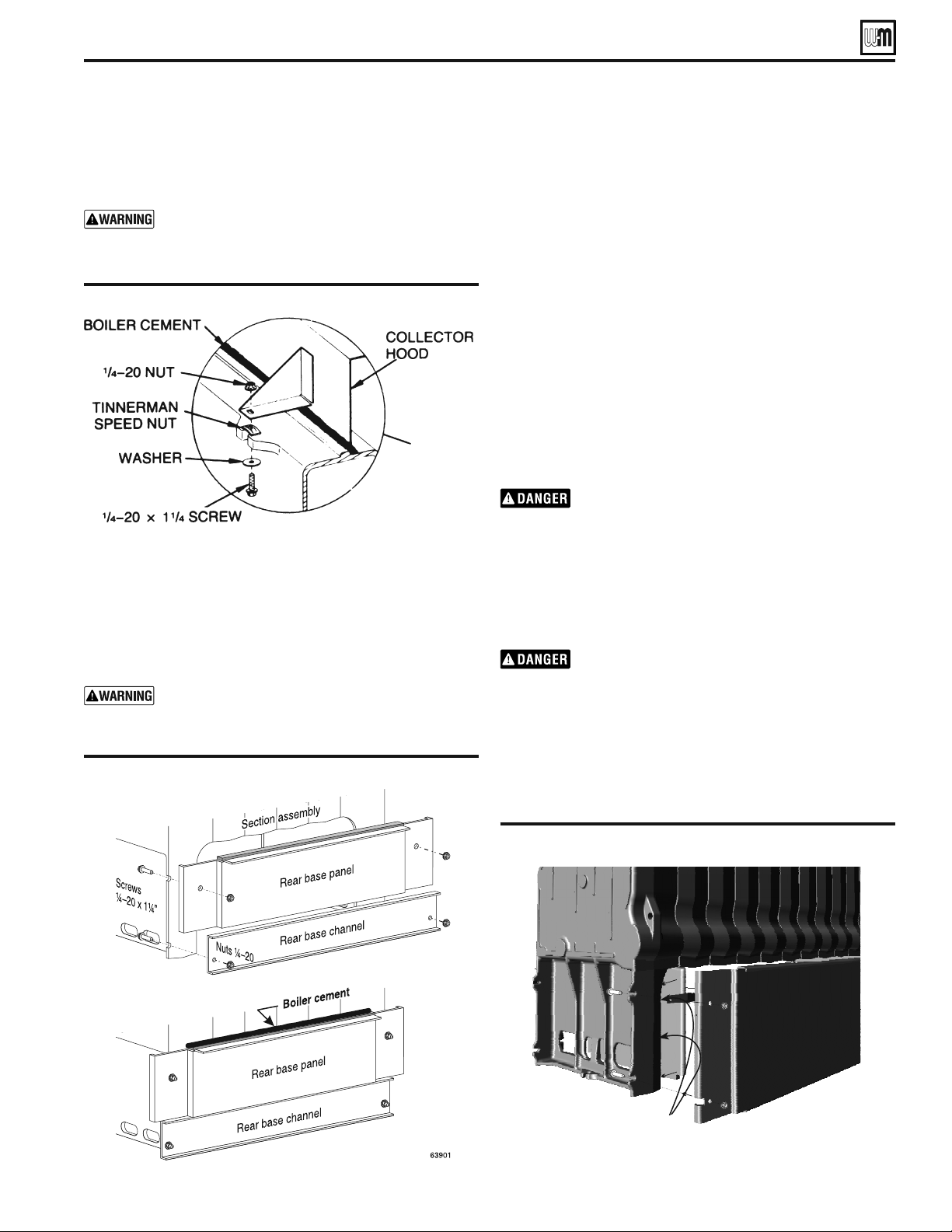
Installation of flue collector hood
(Factory installed on PEG boilers)
Set flue collector hood on boiler as shown in Figure 6b. Use boiler
cement furnished to provide gas-tight seal.
Failure to maintain gas-tight seal can cause flue gas
spillage and carbon monoxide emissions, resulting
in severe personal injury or death.
Installation of rear base panels
(Factory installed on PEG boilers)
&OR%'THROUGHSEE&IGUREAFOR%'(THROUGH
see Figure 7b. Fasten rear base panel (7 5/16 inch high - EG/
PEG - 2 pieces) and rear base (11 17/32 inch high - EGH - 1
piece) channel to section assembly. Seal with boiler cement
along top of insulation panels.
Failure to maintain gas-tight seal can cause flue
gas spillage and carbon monoxide emissions,
resulting in severe personal injury or death.
&IGUREA EG/PEG - Rear base panel and base channel
Prepare tKe EoLler (continued)
Installation of side refractory -EGH only
1. See Figure 7b & 7d. Hardware for drawer assembly must
be installed (See Figure 10), before sliding refractory in to
place.
2. Apply silicone to the inside surface of the cast iron end
section leg.
3. Slide refractory (2 pieces left & right side) into place.
4. Install four (4) refractory clips (See Figure 7b & 7d) to hold
refractory in place.
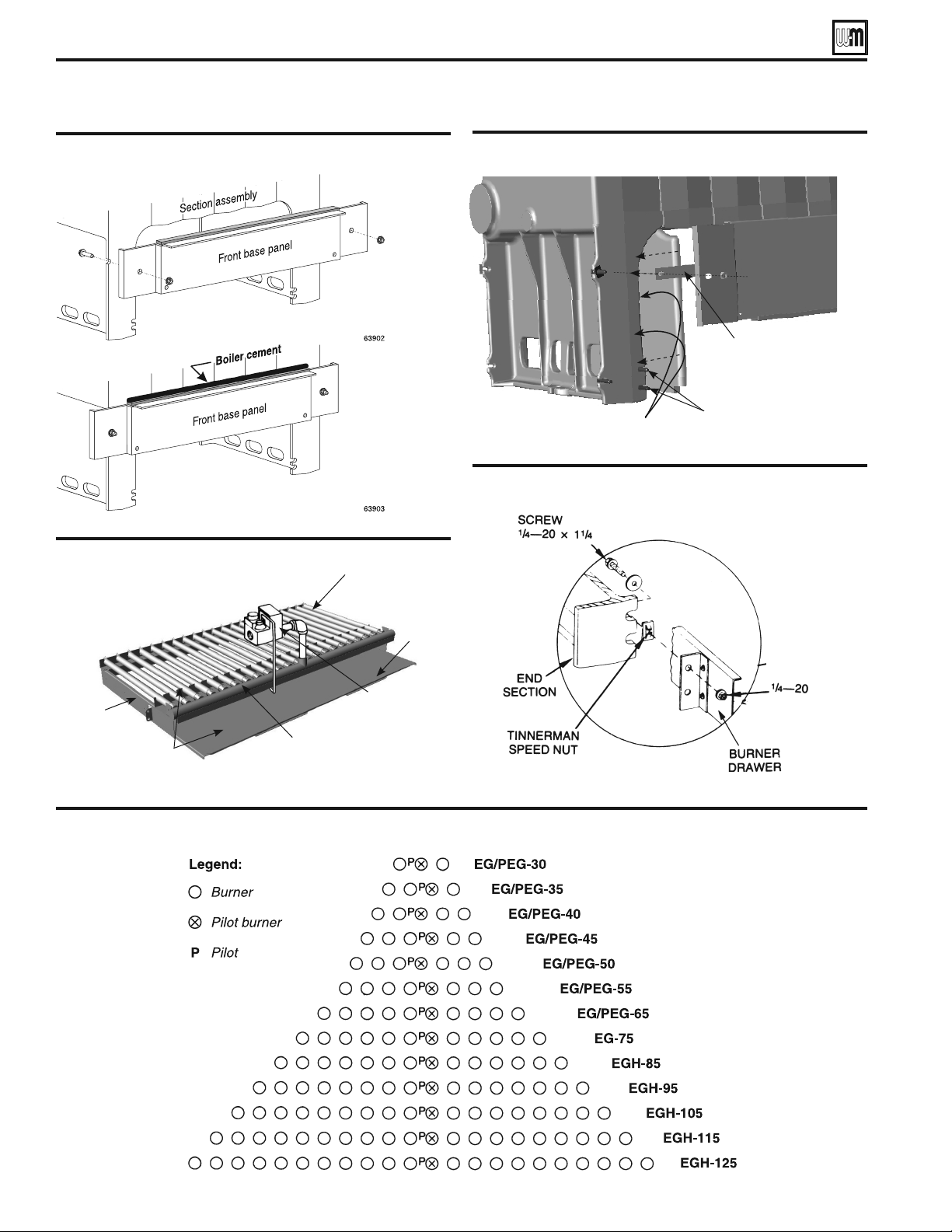
Installation of drawer assembly, front
base panels – EG/EGH
(Factory installed on PEG boilers)
1. See Figure 7c. Fasten front base panel (6 ¹⁄₈ inch high) and
rear base channel to section assembly. Seal with boiler cement
along top of insulation panels.
2. The burner drawer assembly consists of the burner drawer,
main burners, gas manifold, pilot burner, etc.
3. Check for proper orifice sizing from Table 5, page 13.
Proper orifices must be used. Failure to do so will
cause severe personal injury, death or substantial
property damage.
4. 0LACEBURNERSINTHEDRAWERASSEMBLYASSHOWNIN&IGURES
and 9, page 12.
5. Slide the drawer assembly under the front base panel and at-
tach to the section assembly as shown in Figure 10, page 12.
6. Level and straighten burners.
Burners must be properly seated in slots in back
burner support with openings facing up. Gas
orifices must inject down center of burner. Failure
to properly seat burners will result in severe personal
injury, death or substantial property damage.
7.
%'n%' only: Install rollout thermal fuse element with
wire terminals facing up on front access panel as shown in
Figure 11, page 13. Wire per the appropriate Control Supple-
ment.
&IGUREB Flue collector hood
&IGUREB EGH - Rear base panel & refractory and
refractory clip
EG
&
PEG SERIES 5
s
EGH SERIES 5 GAS-FIRED BOILERS — BOILER MANUAL
Note! Silicone to be applied to inside
of leg of cast surface.
3DUW1XPEHU
12
Prepare tKe EoLler (continued)
&IGURE Burner drawer installation
&IGURE Burner and pilot burner locations
&IGURE EGH Burner drawer assembly
&IGUREC %'%'( Front base panel
(Factory installed on PEG boilers)
&IGURED EGH - Refractory placement & front base panel
EG
&
PEG SERIES 5
s
EGH SERIES 5 GAS-FIRED BOILERS — BOILER MANUAL
Burner
&RPELQDWLRQ
Gas Valve
(*+VKRZQ
See page 35
for EG
%XUQHUEDVHVKLHOG
on EGH Boilers only
0DQLIROG
'UDZHU
3LORW%XUQHUQRWVKRZQ
See Figure 9 for locations
)RXUUHIUDFWRU\FOLSVZLOO
KROGUHIUDFWRU\
´+DUGZDUHIRUPRXQWLQJIURQW
DQGUHDUEDVHSDQHOVQHHGVWREHLQ
SODFHEHIRUHUHIUDFWRU\SLHFHVOHIW
ULJKWVLGHDUHVOLGLQWRSODFH
Flange
to front
RIERLOHU
Note! Silicone to be applied to
inside of leg of cast surface.
3DUW1XPEHU
13
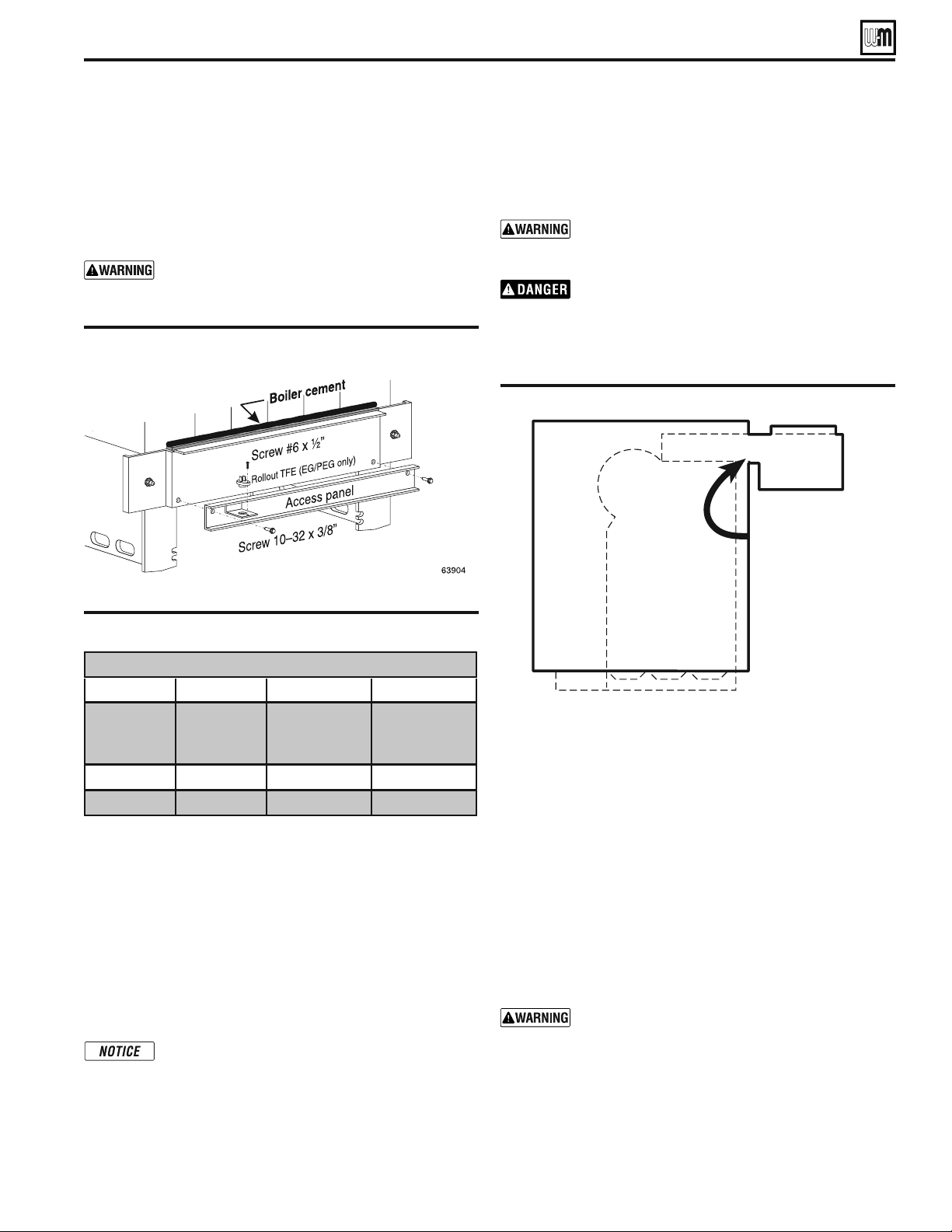
&IGURE EG/EGH - Access panel
&ACTORYINSTALLEDon PEG boilers)
Spill switch installation
%'n%' and 0%'n0%' boilers only, fasten spill
switch to draft hood as shown on page 34, Drawing Ref. Letter “K”.
Connect wires as shown in the appropriate Control Supplement.
Damper installation
If damper will be installed, see Control Supplement for informa-
tion.
Breeching erection
Connect from draft hood or damper outlet to chimney or vent
with same size breeching. Where possible, vertical venting to the
outside from draft hood or damper outlet will offer best perfor-
mance. Where horizontal breeching is used, slope upward at least
1/4 inch per lineal foot toward chimney or vent and support with
hangers to prevent sagging.
A vertical height of 3 feet to 5 feet of breeching before
any elbow or horizontal breeching is recommended
to reduce chances of flue gas spillage at draft hood
on EGH-95 thru -125 boilers (not restricted on any
%'OR%'(,ONGHORIZONTALBREECHINGSEXCES-
sive numbers of elbows or tees, or other obstructions
which restrict the flow of combustion gases should
be avoided.
Breeching must not be connected to any portion of a mechanical
draft system operating under positive pressure.
Inspect burners – PEG boilers
1. PEG boiler are factory-assembled, but the burners and base
panels should be inspected to ensure they are in good condi-
tion.
2. Remove the access panel (Figure 11) and inspect the burners
per step 6 above. Replace the access panel.
Jacket installation (Factory installed on PEG)
1. Remove the proper knockout discs from panels as shown in
Table 4, page 10.
Tankless and storage heater knockouts must be
removed for EG and EGH boilers with optional
tankless heaters prior to jacket installation.
2. Follow Jacket Instructions in jacket carton.
&IGURE Draft hood
Prepare tKe EoLler (continued)
4ABLE Orifice drill sizes
Ori¿ce Drill Sizes
EG/PEG EGH
Type of Gas
Heating
Value
BTU/cu. ft.
6WDQGDUG
2UL¿FH
GULOOVL]H
6WDQGDUG
2UL¿FH
GULOOVL]H
Natural
PP PP
Propane
PP PP
Draft hood installation
Attach draft hood to flue collector hood using #10 x 1/2” sheet
metal screws provided. Use boiler cement furnished to provide
gas tight seal.
Failure to maintain gas-tight seal can cause flue gas
spillage and carbon monoxide emissions, resulting
in severe personal injury or death.
Do not alter boiler draft hood or place any obstruc-
tion or non-approved damper in the breeching or
vent system. CSA certification will become void.
Flue gas spillage and carbon monoxide emissions
will occur causing severe personal injury or death.
Installation of base shield - EGH only
3EE&IGURESLIDEBASESHIELDUNDERBURNERDRAWERASSEM-
bly.
2. The flanged end of the shield should be located at the front
of the boiler.
The installer must install base shield, flanged end of
shield at front of boiler for proper boiler operation.
EG
&
PEG SERIES 5
s
EGH SERIES 5 GAS-FIRED BOILERS — BOILER MANUAL
Seal across back of
block assembly with
boiler cement between
cast iron and sheet
metal edge of draft hood
3DUW1XPEHU
14
General
Install the boiler jacket before connecting return piping. (Supply piping
can be connected before or after jacket installation.) Connect controls
after all piping is connected.
If installation is to comply with ASME or Canadian requirements, an ad-
ditional high temperature limit may be needed. Install control in supply
piping between boiler and isolation valve. Set second control to minimum
20 °F above setpoint of first control. Maximum allowable setpoint is 240
°F. See page 23 for wiring.
A low water cutoff device is required when boiler is installed above radia-
tion level or by certain state or local codes or insurance companies. The
boiler has a pre-installed water temperature sensor. An additional external
low water cutoff device may be used simultaneously if necessary.
Use backflow check valve in cold water supply if required by local codes.
Isolation valves
Isolation valves are required to enable servicing of the boiler’s temperature
sensor. Install as shown in appropriate piping diagram.
Near-boiler piping
Boiler connections
1. EG — Connect supply and return to left end.
2. Plug all unused connections.
Systems operating at or above 130°F
1. See Table 6 and Figure 14 (diaphragm-type or bladder-type expansion
tank) or Figure 13 (closed-type expansion tank) on page 12 for near-
boiler piping for systems designed for return water at least 130 °F.
Low-temperature systems
1. See page 16 (Figures 16 and 17) for near-boiler piping for low-tem-
perature or high-volume systems.
2. See page 15 (Figure 15) for boilers used with refrigeration systems.
Relief valve
Install relief valve vertically in ¾” tapping on side of boiler. See the tag
attached to the relief valve for manufacturer’s instructions.
To avoid water damage or scalding due to valve operation,
discharge line must be connected to relief valve outlet and
run to a safe place of disposal. Terminate the discharge line
to eliminate possibility of severe burns should the valve
discharge.
s $ISCHARGELINEMUSTBEASSHORTASPOSSIBLEANDBETHESAME
size as the valve discharge connection throughout its entire
length.
s $ISCHARGELINEMUSTPITCHDOWNWARDFROMTHEVALVEANDTER-
minate at least 6” above the floor drain where any discharge
will be clearly visible.
s 4HEDISCHARGELINESHALLTERMINATEPLAINNOTTHREADEDWITH
a material serviceable for temperatures of 375 °F or greater.
s $ONOTPIPETHEDISCHARGETOANYPLACEWHEREFREEZINGCOULD
occur.
s .OSHUTOFFVALVESHALLBEINSTALLEDBETWEENTHERELIEFVALVE
and boiler, or in the discharge line. Do not plug or place any
obstruction in the discharge line.
s &AILURETOCOMPLYWITHTHEABOVEGUIDELINESCOULDRESULTIN
failure of the relief valve to operate, resulting in possibility of
severe personal injury, death or substantial property damage.
s 4ESTTHEOPERATIONOFTHEVALVEAFTERlLLINGANDPRESSURIZING
system by lifting the lever. Make sure the valve discharges
freely. If the valve fails to operate correctly, replace it with a
new relief valve.
Circulator
The circulator is not provided, but wiring is pre-
attached to boiler to allow you to locate it either in the
return or supply piping, as desired. See page 12 for a
typical installation. Pipe the expansion tank to the suc-
tion side of the circulator whenever possible. Install an
air separator in the supply piping. Connect the expan-
sion tank to the air separator only if the separator is
on the suction side of the circulator. Always install the
system fill connection at the same point as the expansion
tank connection to the system. Figures 13 and 14 show
typical near-boiler piping connections.
Expansion tank
Diaphragm-type or bladder-type tank — Figure 14
1. Ensure expansion tank size will handle boiler and
system water volume and temperature. Tank must
be located in boiler return piping as close to boiler
as possible, before inlet side of circulator. See tank
manufacturer’s instructions for details.
2. Install an automatic air vent as shown.
Closed-type tank — Figure 13
1. Ensure expansion tank size will handle boiler and
system water volume and temperature. See tank
manufacturer’s instructions for details.
2. Connect tank to ½” NPT tapping located behind
supply outlet, using ½” NPT piping. Pitch any
horizontal piping up towards tank 1 inch per 5 feet
of piping.
Undersized expansion tanks cause system
water to be lost from relief valve and
makeup water to be added through fill
valve. Eventual section failure can result.
Water piping — multiple zone systems
Install system piping using either circulator zoning or
zone valve zoning. Install expansion tank on suction side
of system circulator. Always connect fill line only at the
expansion tank — never at another point in the system.
4ABLE Minimum recommended pipe sizes
ConneFt pLpLnJ ² Zater EoLlers ² (G onl\
Minimum Recommended Pipe Sizes (for 20°F rise)
Boiler
number
Forced-Àow systems Gravity-Àow systems
Supply
“A”
Return
“B”
Supply
“A”
Return
“B”
EG-30, 35
1” 1” 1 ½” 1 ½”
EG-40, 45, 50
1 ¼” 1 ¼” 2” 2”
EG-55, 65
1 ½” 1 ½” 2 ½” 2 ½”
EG-75
2” 2” 2 ½” 2 ½”
Note:
$OOVXSSO\DQGUHWXUQSLSHVL]HVDUHEDVHGXSRQD)
WHPSHUDWXUHULVHWKURXJKWKHERLOHU
EG
&
PEG SERIES 5
s
EGH SERIES 5 GAS-FIRED BOILERS — BOILER MANUAL
3DUW1XPEHU
15
&IGURE Recommended piping – forced hot water boilers
with closed type expansion tanks
&IGURE Recommended piping – forced hot water boilers
with diaphragm type expansion tanks
Water piping — refrigeration systems
Prevent chilled water from entering boiler
Install boiler so that chilled medium is piped in par-
allel with the heating boiler. Use appropriate valves
to prevent chilled medium from entering boiler. See
Figure 15 for typical installation of balancing valve
and check valve.
Use Figure 13 or Figure 14 only for systems designed
for return water at least 130 °F. For systems with
low return water temperature possible, such as con-
verted gravity systems and radiant heating systems,
install bypass piping (see page 16) to protect boiler
against condensation. Failure to prevent low return
water temperature to the boiler could cause corro-
sion of the boiler sections or burners, resulting in
severe personal injury, death or substantial property
damage.
If system includes radiant heating circuits, provide
piping and controls to regulate the temperature sup-
plying the radiant circuits. Failure to comply could
result in substantial property damage.
&IGURE Recommended piping – refrigeration systems
Install boiler so that chilled medium is piped in
parallel with heating boiler (Figure 15). Use ap-
propriate valves to prevent chilled medium from
entering boiler. Consult AHRI Installation and
Piping Guides.
If boiler is connected to heating coils located in
air handling units where they can be exposed to
refrigerated air, use flow control valves or other au-
tomatic means to prevent gravity circulation during
cooling cycle. Circulation of cold water through the
boiler could result in damage to the heat exchanger,
causing possible severe personal injury, death or
substantial property damage.
ConneFt pLpLnJ ² Zater EoLlers ² (G onl\ (continued)
$/./4CONNECTDIRECTLYFROMWIREZONE
VALVESTO THE44 TERMINALS ON THE BOILER
.
When using 3-wire zone valves, install an isolation
relay. Connect the zone valve end switch wires to
the isolation relay coil. Connect the isolation relay
contact across the boiler T-T terminals. Failure
to comply can result in damage to boiler com-
ponents or cause unreliable operation, resulting
in severe property damage.
EG
&
PEG SERIES 5
s
EGH SERIES 5 GAS-FIRED BOILERS — BOILER MANUAL
3DUW1XPEHU
16
&IGURE System bypass piping in boiler loop with separate
system circulator, using primary/secondary
piping.
&IGURE Boiler bypass piping — use only for high water
content systems —DO NOT use for radiant panel
systems.
ConneFt pLpLnJ ² Zater EoLlers ² (G onl\ (continued)
Install all components specified above and adjust valves as described to prevent low temperature in the boiler. Failure to
prevent low water temperature in the boiler could cause corrosion of the boiler sections or burners, resulting in severe
personal injury, death or substantial property damage.
System bypass method
1. Apply bypass piping of Figure 16 to high water content
systems, radiant panel systems or any system that is likely
to operate with low return water temperature for extended
periods.
2. The bypass arrangement shown protects the boiler from dam-
age caused by condensate corrosion due to low return water
temperature and protects low temperature systems from too
high a supply temperature.
3. Adjust the bypass valves as indicated below.
Adjust bypass valves 1 and 2 as follows:
1. Start with valve 2 fully closed, valve 1 fully open.
2. Slowly open valve 2 while closing valve 1. Adjust the valves
until the boiler pressure/temperature gauge reads 160 °F or
higher. As you open the valves, pause long enough to allow
temperatures to level off. It takes a while for the boiler water
temperature to rise as the flow changes.
3. Bypass valve 2 allows hot boiler outlet water to blend with
colder return water, raising the supply temperature to the
boiler. Bypass valve 1 balances the pressure drop through valve
2.
4. The purpose of this piping is to raise the return water temperature
to the boiler enough to prevent condensation of flue gases.
Boiler bypass method
1. Apply bypass piping of Figure 17 to high water content
systems, such as converted gravity systems.
2. The bypass arrangement shown protects the boiler from
damage caused by condensate corrosion due to low return
water temperature. This method does not provide protection
from high temperature water being supplied to the system.
3. DO NOT apply this piping to radiant panel systems.
4. Adjust the bypass valves as indicated below.
Adjust bypass valves 1 and 2 as follows:
1. Start with valve 1 fully closed, valve 2 fully open.
2. Slowly open valve 1 while closing valve 2. Adjust the valves
until the boiler pressure/temperature gauge reads approxi-
mately 60 °F higher than the system temperature gauge. As
you open the valves, pause long enough to allow temperatures
to level off. It takes a while for the boiler water temperature
to rise as the flow changes.
3. Bypass valve 1 controls system flow rate. Bypass valve 2
controls flow through the boiler.
4. The purpose of this piping is to cause a high enough tem-
perature rise in the boiler that the average temperature will
be warm enough to prevent condensation of flue gases.
EG
&
PEG SERIES 5
s
EGH SERIES 5 GAS-FIRED BOILERS — BOILER MANUAL
H
H
A
J
J
J
Water line
Close nipple
Reducing elbow or
elbow with bushing
Condensate return
23 / "
13
16
2"
Boiler
front
Steam to system
73832
EG/PEG
H
H
A
J
J
J
Water line
Close
nipple
Reducing elbow or
elbow with bushing
Condensate
return
23 / "
13
16
2"
Boiler
front
Steam to
system
73832a
Install offset header
to prevent bending
at section tappings
EGH
B
Part Number 550-142-905/0319
17
General
Failure to properly pipe the boiler may result in
improper operation and damage to the boiler or
building.
Steam supply must be on same end as controls.
Return may be from either end.
1. Install the boiler jacket before connecting return piping. (Sup-
ply piping can be connected before or after jacket installation.)
Connect controls after all piping is connected.
2. See Table 7 for recommended pipe sizing.
3. See Figure 5, page 10, for tapping locations.
4. EGH only - install 3/4” system blow-off (drain) valve in lowest
part of return piping close to boiler.
Condensate return —
• Satisfactoryoperationofasteamheatingsystemdepends
on adequate condensate return to boiler to maintain a
steady water level.
• Avoidaddingrawmakeupwater.
• Wherecondensatereturnisnotadequate,installlowwater
cutoff/pump control, condensate receiver and condensate
boiler feed pump. Refer to Table 5, page 16, for sizing.
Connecting to parallel-flow piping
1. See Figure 18 for parallel-flow steam systems.
Connecting to counterflow piping
Whenconnectingtoacounterowsystem,theboilersteamsupply
must connect into the top of the counterflow system header, as
shown in Figure 19, page 18.
Figure 18 Recommended piping for parallel-flow systems
Table 7 Recommended steam boiler pipe sizing
Steam Boiler Piping Minimum Recommended Pipe Sizes
Boiler Model
Riser Pipe Size
Header *
H
Equalizer
J
A B
EG-30, 35
PEG-30, 35
2” –– 2” 1 ½”
EG-40, 45, 50
PEG-40, 45, 50
2 ½” –– 2 ½”
1 ½”
2” 2” 2 ½”
EG-55, 65, 75
PEG-55, 65
2” 2”
3” 1 ½”
3” ––
EGH-85, 95
2” 2” 3” 1 ½”
EGH-105
2 ½” 2 ½” 3” 1 ½”
EGH-115, 125
2 ½” 2 ½” 4” 1 ½”
*
24” minimum from waterline to bottom of header.
Connect piping – steam boilers (continued)
EG
&
PEG sEriEs 5
•
EGH sEriEs 5 Gas-firEd boilErs — boilEr manual
3DUW1XPEHU
Installing the relief valve
Install relief valve in tapping on top of boiler. See Table 4, page
10, for control tapping locations. See the tag attached to the relief
valve for manufacturer’s instructions.
Follow the steps below to avoid potential severe per-
sonal injury, death or substantial property damage.
s 7HENINSTALLINGTHERELIEFVALVEENSURETHATALLCONNEC-
tions, including the valve inlet, are clean and free from
any foreign matter.
s -OUNTTHERELIEFVALVEONLYINTHEVERTICALPOSITIONDIRECTLY
connected to the tapping designated in the manual on top
of the boiler.
s 5SEPIPECOMPOUNDSPARINGLYORTAPEONEXTERNALTHREADS
only.
s $O NOT USE A PIPE WRENCH5SE PROPERTYPE AND SIZE
wrench on wrench pads only.
During operation, this valve may discharge large
amounts of steam and/or hot water. Therefore, to
reduce the potential for bodily injury and property
damage, a discharge line MUST be installed that:
s )SCONNECTEDFROMTHEOUTLETTOASAFEPOINTOFDISCHARGE
with no intervening valve.
s !LLOWSCOMPLETEDRAINAGEOFBOTHTHEVALVEANDTHEDIS-
charge line.
s )SINDEPENDENTLYSUPPORTEDANDSECURELYANCHOREDSOAS
to avoid applied stress as possible.
s 4ERMINATESFREELYTOATMOSPHEREWHEREANYDISCHARGEWILL
be clearly visible and is at no risk of freezing.
s )SOVERITSENTIRELENGTHOFAPIPESIZEEQUALTOORGREATER
than that of the valve outlet.
Use only schedule 40 metal pipe for discharge. (Do not
USESCHEDULEEXTRASTRONGORDOUBLESTRONGPIPEOR
connections.) DO NOT CAP, PLUG OR OTHERWISE
/"3425#4$)3#(!2'%0)0%/54,%4)FDISCHARGE
is piped upward, a condensate drain must be provided in
the elbow below the vertical pipe to prevent condensate
from returning into the valve. Failure to comply with these
instructions will cause a dangerous spray of hot water and
steam that would cause severe personal injury or death.
&IGURE Connection to counterflow steam piping
ConneFt pLpLnJ ² steam EoLlers (continued)
EG
&
PEG SERIES 5
s
EGH SERIES 5 GAS-FIRED BOILERS — BOILER MANUAL
4ABLE Boiler feed system sizing
&IGURE Recommended piping for parallel-flow systems
with optional reservoir pipe
3DUW1XPEHU
19
Condensate return
Modern steam boilers are designed to steam for less time than
older, larger boilers. When replacing an older steam boiler the
system condensate return time may be longer than the steaming
time. This could cause the following problems:
1. Boilers fitted with an automatic water feed could overfill.
2. Units fitted with only a low water cutoff would shut down
and cycle while waiting for condensate to return.
Following is a simple method for determining whether or not a
reservoir pipe is required to lengthen steaming time for a resi-
dential installation:
1. Disconnect condensate return line at existing boiler.
2. Heat
boiler and allow to steam for 10 minutes. Turn off boiler.
3. Measure length of time from when boiler started to steam to
when condensate begins to return through condensate line.
4. Measure length of time from when condensate begins to
return to when it stops returning. Divide this time by 2.
5. Add time measured in step 3 to time calculated in step 4. This
sum is the average time required for condensate to return to
the boiler.
6. If this total time is 10 minutes or less, no reservoir pipe is
needed.
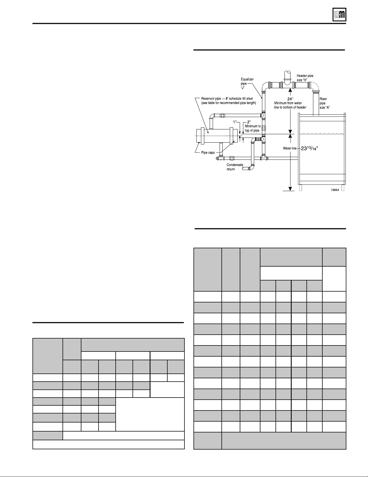
If total time for condensate to return to boiler (from step 5) is
more than 10 minutes, a reservoir pipe (or boiler feed system) is
RECOMMENDED3EE4ABLEAND&IGUREFORSUGGESTEDRESERVOIR
pipe size. Install as shown in Figure 20.
&ORLARGERSYSTEMSASNOTEDIN4ABLEUSEABOILERFEEDSYSTEM
with a condensate tank and feed pump. You will have to install a
low water cutoff/pump control on the boiler to operate the pump.
Use Table 9 to size boiler feed systems. See Figure 5, page 10, for
tapping locations. (The use of a combination condensate tank and
float-controlled condensate return pump is not recommended.)
For most residential installations a reservoir pipe may be all that
is necessary to ensure proper operation.
Boiler
model
number
Max.
boiler
gross
output
Time from initial steaming to average condensate return
ERLOHUVWHDPLQJFDSDFLW\EDVHGRQ%WXSHUSRXQGRIVWHDP
15 minutes 20 minutes 30 minutes
MBH gallons
pipe
length
(feet)
gallons
pipe
length
(feet)
gallons
pipe
length
(feet)
EG/PEG-30,-35
75 ¾ ¾ 1 ½ 1 ½ 3 2 ½
EG/PEG-40,-45
125 1 ¼ 1 ¼ 2 ½ 2 ¼
8VHERLOHUIHHG
V\VWHP
EG/PEG-50
145 1 ½ 1 ½ 3 2 ½
EG/PEG-55
167 1 ¾ 1 ¾
8VHERLOHUIHHG
V\VWHP
EG/PEG-65
209 2 ¼ 2 ¼
EG-75
247 2 ½ 2 ½
EGH-85
243 2 ½ 2 ½
EGH-95 up Not recommended –– Use boiler feed system if needed
'HVLJQHGIXOOFDSDFLW\VWHDPLQJWLPHRIPRGHUQERLOHUVLVPLQXWHV
4ABLE Reservoir pipe sizing
Boiler
Model
Gross
Output
Pounds
Steam
Per
Hour
Gallons
Conden-
sate
Per
Hour
Minimum Condensate
Receiver Capacity (Gal.)
Recom-
mended
Maximum
Minutes of boiler
operation:
Feed
Pump
Capacity
GPM
*
15 30 45 60
EG/PEG-30
65 7 ½ 2 5 7 10 0.3
EG/PEG-35
86 10 3 7 10 13 0.3
EG/PEG-40
108 12 ½ 4 8 12 17 0.4
EG/PEG-45
130 15 5 10 15 20 0.5
EG/PEG-50
151 17 ½ 6121723 0.6
EG/PEG-55
174 20 7 13 20 27 0.7
EG/PEG-65
218 25 8 17 25 33 0.8
EG-75
257 29 ½ 10 20 29 39 1.0
EGH-85
253 29 10 19 29 39 1.0
EGH-95
290 33 ½ 11 22 33 45 1.1
EGH-105
325 37 ½ 12 25 37 50 1.3
EGH-115
361 41 ½ 14 28 41 55 1.4
EGH-125
398 46 15 31 45 61 1.5
*
,ISXPSFDSDFLW\H[FHHGVFDSDFLW\VKRZQSXPSFDQ
EHWKURWWOHGZLWKJOREHRUEDOOYDOYH
ConneFt pLpLnJ ² steam EoLlers (continued)
EG
&
PEG SERIES 5
s
EGH SERIES 5 GAS-FIRED BOILERS — BOILER MANUAL
3DUW1XPEHU
20
Failure to properly install, pipe and wire boiler
controls may result in severe damage to the
boiler, building and personnel.
Water boiler - EG only
1. Install controls as shown on Control Tapping Table and
Figure 5, page 10.
2. Low water cut off for water boilers:
a) Must be installed if boiler is located above radiation level.
b) May be required on water boilers by certain state, lo-
cal or territorial codes or insurance companies. If
a low water cut-off is used on a water boiler, use a
control designed especially for water installations.
An electrode probe type may be located in a tee in the
supply line above boiler, also see Table 4, page 10.
3. If system is to be ASME inspected and approved, an ad-
ditional high temperature limit is needed. Purchase and
install in supply line above boiler.
Steam boiler - EG, PEG & EGH
Water line dimension are measured from bot-
tom of boiler section leg where it rests on the
boiler room floor or boiler foundation.
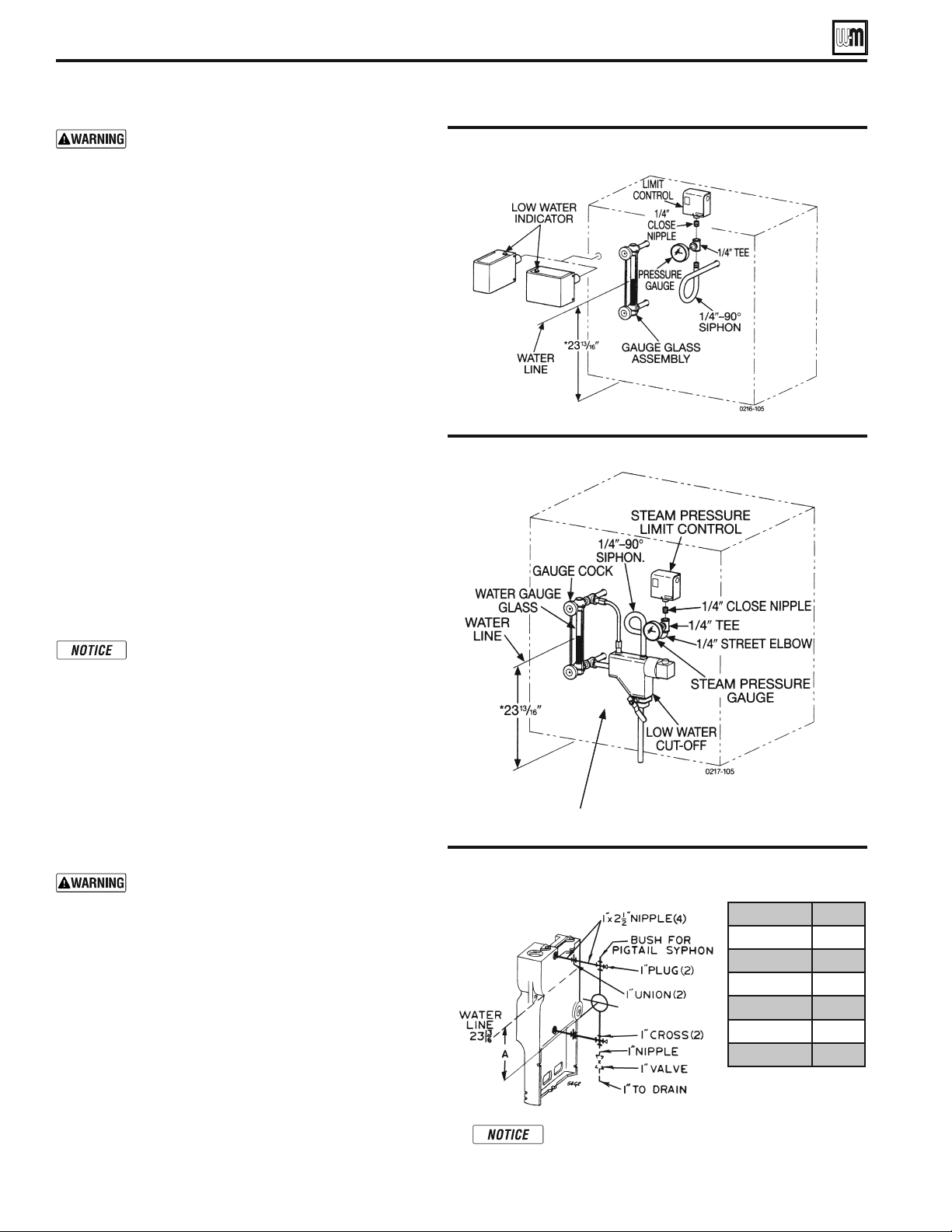
1. For steam boilers furnished with probe-type low water
cut-offs, install as shown in Figure 21.
2. For steam boilers furnished with float type low water
cut-off, install controls as illustrated in Figure 22.
Install blowdown line in bottom of cutoff. See Figure 22
and control manufacturer’s instructions for details.
Pipe blowdown line near floor close to floor
drain to eliminate potential of severe burns.
Do not plug, valve or place any obstruction in
blowdown line.
a) Other float-type water-level controls for EGH steam boilers
are shown in Figure 23. (Use 1 inch I.P.S. connections).
b) Water feeders are not recommended for primary control.
A low-water cut-off with pump controller is recommended
with a condensate receiver and feed pump.
3. Install remaining controls as shown in Table 4 and Fig-
ure 5, page 10.
,nstall EoLler Fontrols
&IGURE %'(ONLY - Piping for optional float-type water level
controllers for steam boilers
LWCO model numbers are manufacturer’s part
numbers that can be found in the Weil-McLain
Trade Price Schedule.
LWCO Dim A.
No. 247-2
7
³/16”
No. 61 ǫ´
No. 63 ǫ´
No. 51-2 1 ½”
1R 2 ¼”
No. 93 ǫ´
3ULPDU\ÀRDW/:&2RUVHFRQGDU\PDQXDO
UHVHW/:&2ZLWKSULPDU\SUREH/:&2
EG
&
PEG SERIES 5
s
EGH SERIES 5 GAS-FIRED BOILERS — BOILER MANUAL
&IGURE Probe-type low water cut-off
&IGURE Float-type low water cut-off
3DUW1XPEHU
21
EG and EGH boilers for tankless heater applica-
tion are available only on special order as factory-
installed optional equipment. Standard boilers
cannot be adapted for heater use. Install a tankless
heater only in a steam boiler or forced hot water.
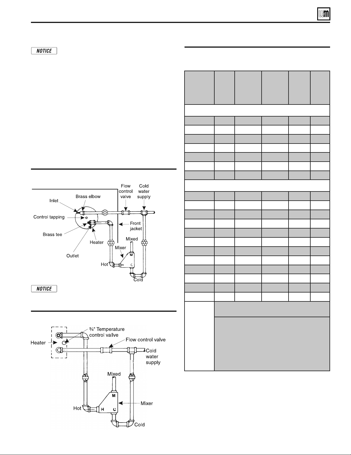
For correct operation, install as shown in Figure 24 (water boilers)
or Figure 25 (steam boilers).
1. Automatic mixing valve must be installed per mixing valve
manufacturer’s instructions.
2. Flow regulating valve must be installed. Size according to
intermittent draw of heater as shown in following table.
3. Operating control with a small differential scale is recom-
mended. Install in temperature control tapping in heater plate.
4. In hard water areas, it is advisable to soften cold domestic
supply water to the tankless heater to prevent lime buildup.
&IGURE Tankless heater piping EG (water boiler)
ConneFt pLpLnJ ² tanNless Keater optLonal
4ABLE Minimum recommended pipe sizes
Piping Connections not furnished. Use brass plugs
in tees and crosses to facilitate cleaning in hard
water areas.
&IGURE Tankless heater piping EG/PEG/EGH (steam boiler)
Boiler Model
Heating
Number
(Note 3)
Intermittent
Draw GPM
100°F Av.
Temp. Rise
(Note 1)
Continuous
Draw GPM
100°F Av.
Temp. Rise
(Note 2)
Inlet and
Outlet
Tappings
Temp.
Control
Tapping
Water
EG-35 E-624 3.00 1.60
½” ¾”
EG-40 E-624 3.00 2.00
½” ¾”
EG-45 E-624 3.25 2.40
½” ¾”
EG-50 E-626 4.00 2.80
½” ¾”
EG-55 E-626 4.25 3.20
½” ¾”
EG-65 E-632 4.50 4.00
½” ¾”
EG-75 E-632 4.50 4.80
½” ¾”
Steam
EG/PEG-35 35-S-29 3.00 1.60
¾” ¾”
EG/PEG-40 35-S-29 3.00 2.00
¾” ¾”
EG/PEG-45 35-S-29 3.25 2.40
¾” ¾”
EG/PEG-50 35-S-29 3.25 2.80
¾” ¾”
EG/PEG-55 35-S-29 3.50 3.20
¾” ¾”
EG/PEG-65 35-S-29 3.75 4.00
¾” ¾”
EG-75 35-S-29 4.00 4.80
¾” ¾”
EGH-85 35-S-29 4.00 5.00
¾” ¾”
EGH-95 35-S-29 4.00 5.00
¾” ¾”
EGH-105 35-S-29 4.00 5.00
¾” ¾”
EGH-115 35-S-29 4.00 5.00
¾” ¾”
EGH-125 35-S-29 4.00 5.00
¾” ¾”
127(6
:HLO0F/DLQUDWLQJVEDVHGRQ36,*GRPHVWLFZDWHUSUHV-
sure at heater.
*DOORQVRIZDWHUSHUPLQXWHKHDWHGIURP)WR)
ZLWK)ERLOHUZDWHUWHPSHUDWXUH
&RQWLQXRXVGUDZ±QRUHFRYHU\SHULRG
7KHVHVLQJOHZDOOKHDWH[FKDQJHUVFRPSO\ZLWK1DWLRQDO
6WDQGDUG3OXPELQJ&RGHSURYLGHGWKDW
ERLOHUZDWHULQFOXGLQJDGGLWLYHVLVSUDFWLFDOO\QRQWR[LF
KDYLQJDWR[LFLW\UDQJHRUFODVVRIDVOLVWHGLQ&OLQLFDO
7R[LFRORJ\RI&RPPHUFLDO3URGXFWVDQG
ERLOHUZDWHUSUHVVXUHLVOLPLWHGWRPD[36,*E\
DSSURYHGZDWHURUVWHDPUHOLHIYDOYH
EG
&
PEG SERIES 5
s
EGH SERIES 5 GAS-FIRED BOILERS — BOILER MANUAL
3DUW1XPEHU
22
Connecting gas supply piping
1. Size gas piping considering:
a) Diameter and length of gas supplying piping.
b) Number of fittings.
c) Maximum gas consumption (including any possible future
expansion).
d) Allowable loss in gas pressure from gas meter outlet to boiler.
For pressure drops, see ANSI Z223.1/NFPA 54 - latest edition.
Canadian installations must comply with Natural Gas and Pro-
pane Installation Code, CAN/CSA B149.1 or B149.2 Installation
Codes.
2. For natural gas:
a) Refer to Table 11 or the National Fuel Gas Code. To obtain cubic
feet per hour, divide the input by 1000.
b) Size for rated boiler input.
c) Inlet gas pressure: 5” W.C. minimum
13”
W.C. maximum
d) Manifold gas pressure: 3¹⁄₂"
W.C.
e) Install 100% lock-up gas pressure regulator in supply line if inlet
pressure exceeds 13" W.C., then adjust for 13" W.C. maximum.
3. For propane gas:
a) Inlet gas pressure: 11” W.C. minimum
13” W.C. maximum
b) Manifold gas pressure: 10” W.C.
c) Gas pressure regulator provided by gas supplier must be adjusted
for maximum pressure of 13”
W.C.
d) Contact gas supplier to size pipes, tanks and regulator.
4. Remove knock-out disc from jacket panel which gas supply
is to be piped.
5. Follow good piping practices.
6. Pipe joint compound (pipe dope) must be resistant to cor-
rosive action of liquefied petroleum gases. Apply sparingly
only to make threads of pipe joints.
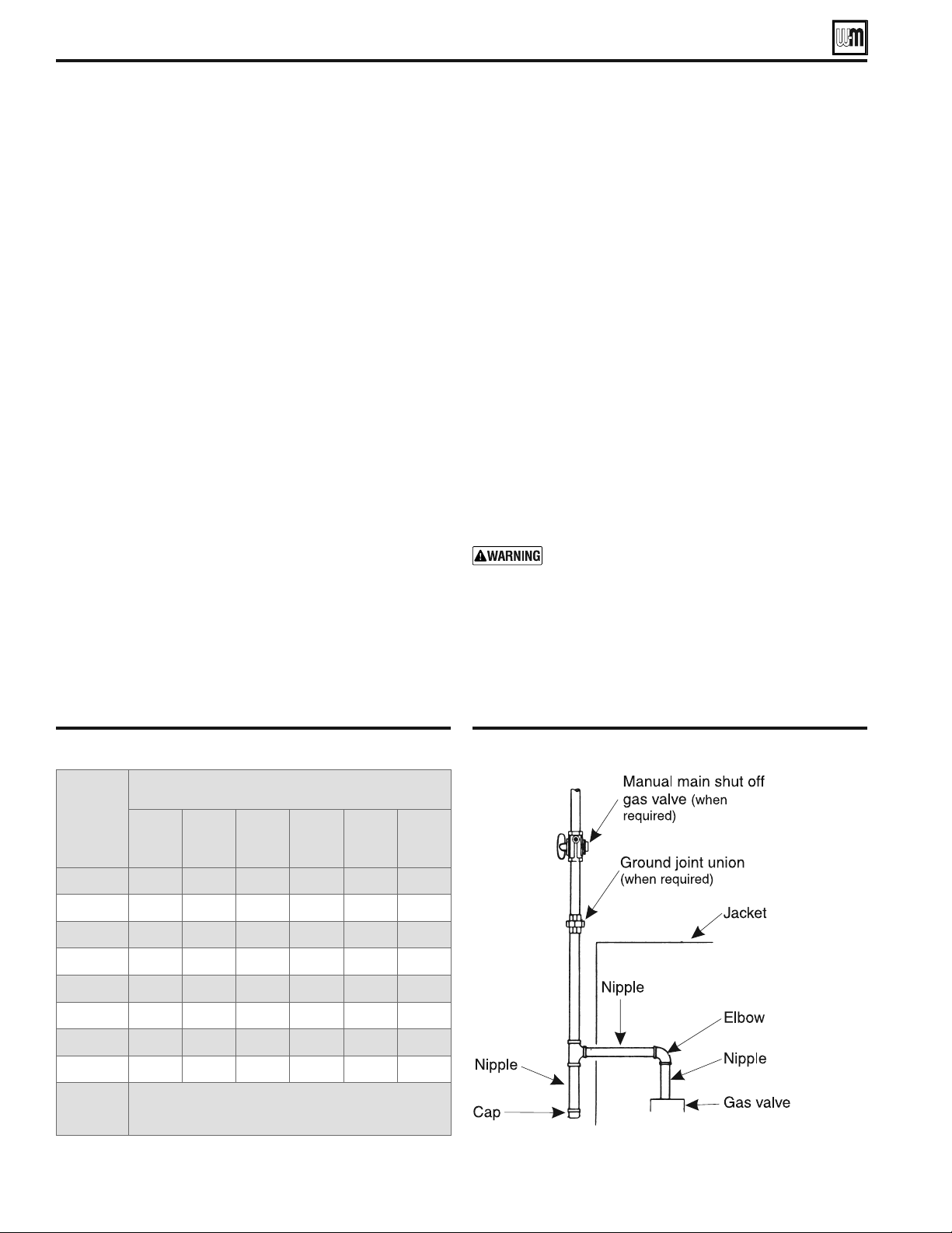
7. Install drip leg at inlet of gas connection to boiler. Where local
utility requires, extend drip leg to floor.
)NSTALLGROUNDJOINTUNIONWHENREQUIREDFORSERVICING3EE
Figure 26.
9. Install manual shut-off valve outside boiler jacket as shown
in Figure 26 when required by local codes.
10. Support piping by hangers, not by boiler or its accessories.
11. In Canada only, the manual main shut off valve (when used)
must be identified by the installer.
12. Purge all air from piping.
13. Before placing boiler in operation, check boiler and its gas
connection for leaks.
Do not check for gas leaks with an open flame – use
bubble test. Failure to do so can cause severe per-
sonal injury, death or substantial property damage.
a) Close manual main shut-off valve during any pressure testing
at less than 13 inches water column.
b) Disconnect boiler and gas valve from gas supply piping during
any pressure test greater than 13 inches water column.
&IGURE Gas supply piping
ConneFt Jas suppl\ pLpLnJ
4ABLE Gas pipe capacities
Adjusted
length
of gas
supply
piping in
feet *
Capacity of pipe for pipe sizes in
cubic feet of gas per hour **
½” ¾” 1” 1¼” 1½” 2”
10 132 278 520 1050 1600 3050
20 92 190 350 730 1100 2100
30 73 152 285 590 860 1650
40 63 130 245 500 760 1450
50 56 115 215 440 670 1270
75 45 93 175 360 545 1020
100 38 79 150 305 460 870
150 31 64 120 250 380 710
Notes *
Include measured length of gas supply piping and allowance
in feet for number and size of fittings.
**
Specific Gravity - 0.60; Pressure loss - 0.30” w.c.
EG
&
PEG SERIES 5
s
EGH SERIES 5 GAS-FIRED BOILERS — BOILER MANUAL
3DUW1XPEHU
23
For your safety, turn off electrical power supply at ser-
vice entrance panel before making any electrical con-
nections to avoid possible electric shock hazard. Fail-
ure to do so can cause severe personal injury or death.
Refer to the Control Supplement for additional
information, operating instructions and control
wiring diagram.
Wiring must be N.E.C. Class 1.
If rollout thermal fuse element wire supplied with
boiler must be replaced, type 200 °C wire or equiva-
lent must be used. If other original wiring supplied
with boiler must be replaced, use only type 105 °C
wire or equivalent.
Boiler must be electrically grounded as required
by National Electrical Code ANSI/NFPA 70–latest
edition.
Electrical installation must comply with:
1. National Electrical Code ANSI/NFPA 70–latest edition and any
other national, state, provincial or local codes or regulations.
2. In Canada, CSA C22.1 Canadian Electrical Code Part 1, and
any local codes
Wiring connections
1. Boiler is shipped with controls completely wired, except
spill switch and vent damper. See wiring diagram in Control
Supplement for details.
2. Installer must attach wiring diagram inside jacket door.
3. See Figure 26 for field wiring. A separate 120VAC electrical
circuit with a fused disconnect switch (15 amp recommended)
should be used for the boiler.
4. A strain relief bushing and adapter must be used at each point
where wiring passes through control case (see Figure 27) to
protect wiring insulation.
5. Multiple zones — Refer to zone valve manufacturer’s literature
for wiring and application. A separate transformer is required
to power zone valves. Zoning with circulators requires a relay
for each circuit.
Room thermostat
1. Connect thermostat as shown on wiring diagram on boiler.
2. Install on inside wall away from influences of drafts, hot or
cold water pipes, lighting fixtures, television, sunrays or fire-
places.
3. If thermostat has a heat anticipator, set heat anticipator in
thermostat to match power requirements of equipment con-
nected to it. Refer to the appropriate Control Supplement for
instructions on the thermostat anticipator setting.
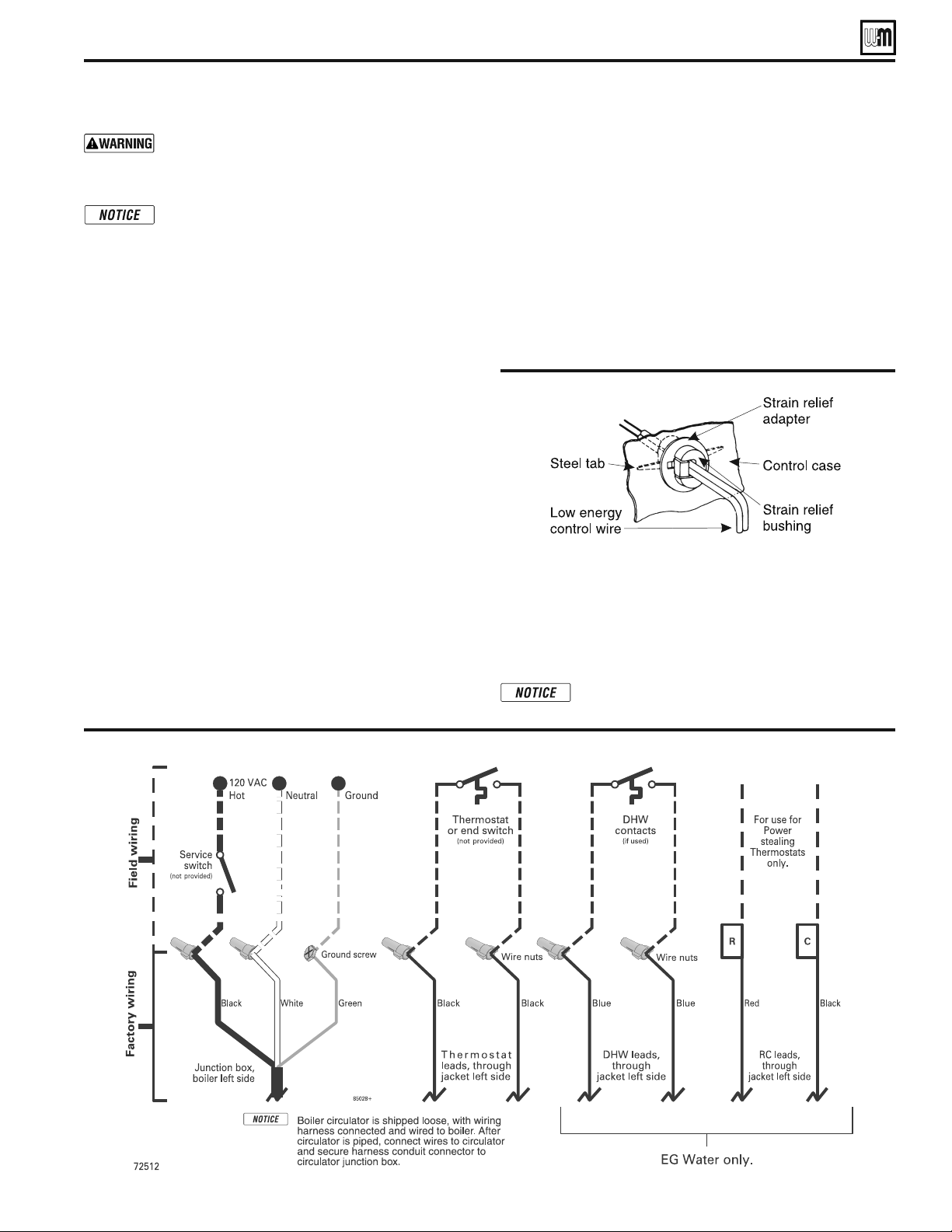
&IGURE Provide strain relief
ConneFt Àeld ZLrLnJ to EoLler
&IGURE Connect field wiring in boiler junction box as shown below. See Control Supplement for more details.
DHW (if used)
Connect the DHW aquastat as shown in wiring below. The
Economy function of the control is not utilized with DHW
input.
R & C Connections (if used)
6!#LEADSSHOULDBEUSEDFORPOWERSTEALINGTHERMOSTATSONLY
Other devices requiring 24 VAC should have sepa-
rate power supply.
EG
&
PEG SERIES 5
s
EGH SERIES 5 GAS-FIRED BOILERS — BOILER MANUAL

3DUW1XPEHU
24
Freeze protection (when used)
Use antifreeze especially made for hydronic systems. Inhibited
propylene glycol is recommended.
Do not use automotive, ethylene glycol or undiluted
antifreeze. Severe personal injury, death or substan-
tial property damage can result.
A 50% glycol solution provides protection to about -30°F.
Local codes may require back-flow preventer or actual disconnect
from city water supply.
Determine quantity according to system water content. Boiler
WATERCONTENTISLISTEDONPAGE2EMEMBERTOADDINEXPANSION
tank water content.
Follow antifreeze manufacturer’s instructions.
Filling water systems
1. Close manual air vents, drain cock, and automatic air vent, if
used.
2. Fill to correct system pressure. Correct pressure will vary with
each application. Residential systems are often designed for
12 PSIG of cold fill pressure.
3. Open automatic air vent one turn, if used.
4. Open manual water feed valve.
a) Starting on lowest floor, open air vents one at a time until
water squirts out. Close vent.
b) Repeat with remaining vents.
5. Close manual water feed valve when correct boiler pressure
is reached.
6. If purge valve is used - located in the return piping above
isolation valve:
a) Connect hose to purge valve.
b) Close isolation valve. Open purge valve.
c) Open hand water feed valve and allow system to purge all
air. If system has more than one circuit, purge each circuit
separately by opening each balancing valve one at a time.
d) Close purge valve and water feed valve cock.
e) Open isolation valve.
f) Fill system to correct pressure.
Filling steam boilers
1. Fill to normal waterline, halfway up gauge glass.
"OILERWATERP(TOISRECOMMENDED
3. Follow skimming procedure.
Wiring multiple zones
Refer to zone valve manufacturer’s literature for wiring and ap-
plication. A separate transformer is required to power zone valves.
Zoning with circulators requires a relay for each circulator.
$/./4CONNECTDIRECTLYFROMWIRE
ZONEVALVESTOTHE44TERMINALSONTHE
BOILER
. When using 3-wire zone valves, install
an isolation relay. Connect the zone valve
end switch wires to the isolation relay coil.
Connect the isolation relay contact across the
boiler T-T terminals. Failure to comply can
result in damage to boiler components or
cause unreliable operation, resulting in severe
property damage.
Check for gas leaks
Before starting the boiler, and during initial opera-
tion, smell near the floor and around the boiler for
gas odorant or any unusual odor. Do not proceed
with start-up if there is any indication of a gas leak.
Repair any leak at once.
Propane boilers only — Your propane supplier mixes
an odorant with the propane to make its presence
detectable. In some instances, the odorant can fade
and the gas may no longer have an odor.
s 0ROPANEGASCAN ACCUMULATEATmOORLEVEL 3MELL
near the floor for the gas odorant or any unusual
odor. If you suspect a leak, do not attempt to light
the pilot.
s 5SECAUTIONWHENATTEMPTINGTOLIGHTTHEPROPANE
pilot. This should be done by a qualified service
technician, particularly if pilot outages are common.
s 0ERIODICALLYCHECKTHEODORANTLEVELOFYOURGAS
s )NSPECTBOILER ANDSYSTEMATLEASTYEARLYTOMAKE
sure all gas piping is leak-tight.
s #ONSULTYOURPROPANESUPPLIERREGARDINGINSTALLA-
tion of a gas leak detector. There are some products
on the market intended for this purpose. Your sup-
plier may be able to suggest an appropriate device.
Fill the system
Do not fill (except for leakage tests) until the boiler
is ready to be fired.
Determine if water treatment is needed
Do not use petroleum-based cleaning or sealing
compounds in boiler system. Severe damage to
boiler will occur, resulting in substantial property
damage.
Eliminate all system leaks. Continual fresh makeup
water will reduce boiler life. Minerals can build up
in sections, reducing heat transfer, overheating cast
iron, and causing section failure.
Consult local water treatment companies for unusually hard water
areas (above 7 grains hardness) or low pH water conditions (below
"OILERWATERP(OFTOISRECOMMENDED
Start-up
EG
&
PEG SERIES 5
s
EGH SERIES 5 GAS-FIRED BOILERS — BOILER MANUAL
3DUW1XPEHU
25
Operate boiler
Check system and boiler
DO NOT proceed with boiler operation unless
boiler and system have been filled with water and
all instructions and procedures of previous manual
sections have been completed. Failure to do so could
result in severe personal injury, death or substantial
property damage.
Before starting the boiler . . .
s 3EE #ONTROL3UPPLEMENTFORh
Operating Instruc-
tions”.
s 6ERIFYTHEBOILERANDSYSTEMWATERLEVELISCORRECT
(Steam — no more than ½ of gauge glass or less
than ¼” above bottom of gauge glass).
s 6ERIFYTHEh0REPARATIONvPROCEDURESONTHEPREVIOUS
pages have been completed.
Start the boiler
1. Steam boilers — Check boiler water level — Should be ap-
proximately ½ way up gauge glass.
2. Remove boiler jacket door and note the gas valve manufacturer
and model number.
3. Follow the Lighting or Operating Instructions in the Control
Supplement, depending on gas valve installed in boiler. Use
only the Operating Instruction which applies to this gas valve.
(The Operating Instruction label on the boiler provides the
same information.)
4. If boiler fails to start, see “If boiler doesn’t start . . . Check for:”
on the next page.
Check system and boiler
Eliminate all system leaks. Continual fresh makeup
water will reduce boiler life. Minerals can build up
in sections, reducing heat transfer, overheating cast
iron, and causing section failure.
If you discover evidence of any gas leak, shut down
the boiler at once. Find the leak source with bubble
test and repair immediately. Do not start boiler
again until corrected. Failure to comply could re-
sult in severe personal injury, death or substantial
property damage.
Do not use petroleum-based cleaning or sealing
compounds in boiler system. Severe damage to
boiler will occur, resulting in substantial property
damage.
1. Check system piping for leaks. If found, shut down boiler and
repair immediately.
2. Inspect vent system thoroughly for signs of deterioration from
corrosion, physical damage or sagging. Verify that masonry
chimney liners are in good condition, with no obstructions,
and there are no openings into the chimney.
3. Check around the boiler for gas leaks following the procedure
of step 13, page 22.
4. Verify operation using procedures below. Perform “Checkout
procedure”, page 27, and fill in the “Installation and Service
Certificate”.
Skim the steam boiler
Clean all newly installed steam boilers to remove
oil and grease. Failure to properly clean can result
in violent fluctuations of water level, water passing
into steam mains or high maintenance costs on
strainers, traps and vents.
Do not use petroleum-based cleaning or sealing
compounds in boiler system. Severe damage to
boiler will occur, resulting in substantial property
damage.
1. Provide 1½” piping from skim tapping to floor drain.
2. Adjust waterline to midpoint of skim tapping. See Figure 5,
page 10.
3. Follow “
Operating Instructions” in the Control Supplement
to fire boiler to maintain temperature below steaming rate.
4. Feed in water to maintain water level. Cycle burners to prevent
rise in steam pressure.
5. Continue skimming until discharge is clear. May take several
hours.
6. Drain boiler. While boiler is warm, but not hot, flush all inte-
rior surfaces under full pressure until drain water runs clear.
7. Remove skim piping. Plug tapping.
#LOSEDRAINCOCK&ILLWITHFRESHWATERTOWATERLINE3TARTBURN-
ers and steam for 15 minutes to remove dissolved gases. Stop
burners.
9. Check traps and air vents for proper operation.
10. Process may need to be repeated after several weeks of opera-
tion.
Inspect base insulation
The boiler contains ceramic fiber and fiberglass
materials. Use care when handling these materials
per instructions on page 33 of this manual. Failure
to comply could result in severe personal injury.
Check to make sure insulation is secure against all four sides of
the base. If insulation is damaged or displaced, do not operate
boiler. Replace or reposition insulation.
Failure to replace damaged insulation or reposition
insulation can result in a fire hazard, causing se-
vere personal injury, death or substantial property
damage.
Start-up (continued)
EG
&
PEG SERIES 5
s
EGH SERIES 5 GAS-FIRED BOILERS — BOILER MANUAL
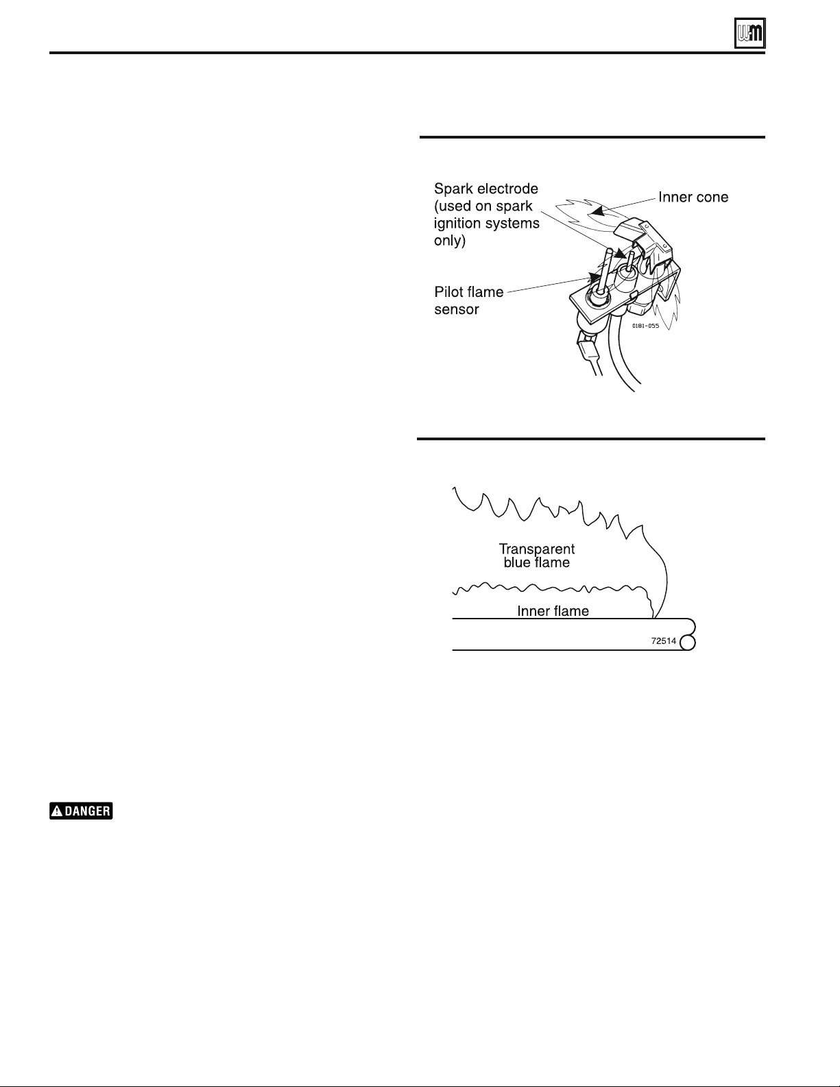
3DUW1XPEHU
26
4. Repeat Steps 2 through 4 several times to verify operation.
5. Return thermostat to normal setting.
6. Set thermostat heat anticipator setting indicated on wiring
diagram.
Check venting system operation
With boiler firing, hold a candle or match below lower edge of
draft diverter “skirt.” If flame does not blow out, but burns undis-
turbed, the vent system is working properly. If flame blows out or
flickers severely, the vent system must be checked for obstructions
or other causes of improper venting.
Verify operation
Check burner flame — Pilot burner
0ROPERPILOTmAMESEE&IGURE
a. Blue flame.
b. Inner cone engulfing thermocouple.
c. Thermocouple glowing cherry red.
2. Proper pilot flame:
a. Overfired — Large flame lifting or blowing past thermocouple.
b. Underfired — Small flame. Inner cone not engulfing thermo-
couple.
c. Lack of primary air — Yellow flame tip.
d. Incorrectly heated thermocouple.
Check burner flame — Main burner
1. Proper main burner flame (see Figure 29):
a. Yellow-orange streaks may appear (caused by dust).
2. Improper main burner flame:
a. Overfired — Large flames.
b. Underfired — Small flames.
c. Lack of primary air — Yellow tipping on flames (sooting will
occur).
Check vent damper operation
1. Raise room thermostat to call for heat — Vent damper actua-
tor will slowly open vent damper.
2.
7HENVENTDAMPERISFULLYOPEN — Pilot will light, then
allow main burners to ignite.
Vent damper must be fully open before main burn-
ers light. If vent damper does not fully open, flue
products such as carbon monoxide will escape into
house, causing severe personal injury or death.
3. Lower thermostat setting — Main burner flames will go out,
then vent damper will close.
Start-up (continued)
If boiler doesn’t start . . . Check for:
1. Loose connections, blown fuse or service switch off?
2. High limit switch set below boiler pressure?
3. Thermostat set below room temperature?
4. Gas not turned on at meter or boiler?
5. Incoming gas pressure less than:
5” w.c. for natural gas? 11” w.c. for propane gas?
6. If none of the above corrects the problem, see “Troubleshoot-
ing” in the Control Supplement.
&IGURE Typical pilot burner flame
&IGURE Typical main burner flame
EG
&
PEG SERIES 5
s
EGH SERIES 5 GAS-FIRED BOILERS — BOILER MANUAL
3DUW1XPEHU
27
Check-out procedure
Check-off steps as completed.
❏ System properly filled with water?
❏ Automatic air vent, if used, open one turn (water boilers only)?
❏ Air purged from system (water boilers only)?
❏ Steam boilers properly skimmed?
❏ Air purged from gas piping? Piping checked for leaks?
❏ Are proper orifices installed? Check page 11 for proper size.
Proper orifices must be used. Failure to do so will
cause severe personal injury, death or substantial
property damage.
❏ Follow operating instruction label on boiler for proper start-
up. Also refer to “Operate boiler,” page 25.
❏ Proper burner flame? See “Check burner flame — Main
burner” and “Check burner flame — Pilot burner,” page 26.
❏ Test temperature limit — While burners are operating, turn
Boiler Temp adjustment knob counterclockwise until display
reading is below actual boiler water temperature. Burners
should go off while circulator continues to operate (water
boilers only). Turn Boiler Temp adjustment knob clockwise
until display reading is above boiler water temperature and
ignition sequence should resume.
❏ Test any additional field-installed controls: If boiler has an
additional low water cut off, additional high limit or other
controls, test for operation as outlined by manufacturer.
Burners should be operating and should go off when con-
trols are tested. When controls are restored, burners should
reignite.
❏ EG only - button on spill switch pushed in?
❏ To test ignition system shut-off device:
Connect manometer to outlet side of gas valve. Start
boiler, allowing for normal start-up cycle to occur and
main burners to ignite. With main burners on, manually
shut off gas supply at manual main shutoff gas valve. Burn-
ers should go off. Open manual main shut-off gas valve.
Manometer should confirm there is no gas flow. Pilot will
relight, flame sensing element will sense pilot flame and
main burners reignite.
❏ Set Boiler Temp adjustment knob to system temperature re-
quirements. Adjust balancing valves and controls to provide
design temperature to system. (water boilers)
❏ Limit control set to design temperature or pressure require-
ments of system? Maximum limit setting - 240°F - 15#
(steam boilers).
❏ For multiple zones, flow adjusted so it is about the same in
each zone (water boilers only)?
❏ Thermostat heat anticipator set properly? Refer to “Room
Thermostat,” page 20 and correct wiring diagram.
❏ Boiler cycled with the thermostat? Raise to highest setting.
Boiler should go through normal start-up cycle. Lower to
lowest setting. Boiler should go off.
❏ Measure gas input (natural gas only):
a. Operate boiler 10 minutes.
b. Turn off other appliances.
c. At the natural gas meter, measure time (in seconds) required to
use one cubic foot of gas.
d. Calculate gas input:
3600 x 1000
number of seconds from step c
= Btuh
e. Btuh calculated should approximate input rating on rating label.
❏ Check manifold gas pressure by connecting a manometer
to the downstream test tapping on main gas valve.
MANIFOLD GAS PRESSURE
NAT = 3.5" W.C.
LP = 10.0"
W.C.
❏ Several operating cycles observed for proper operation? If
damper is provided, see Control Supplement for check- out
procedure.
❏ Room thermostat set to desired temperature?
❏ Installation and Service Certificate on this page completed?
❏ All instructions shipped with this boiler reviewed with owner
or maintenance person, returned to envelope and given to
owner or displayed near boiler?
Start-up (continued)
Installation and service certificate
Boiler model __________________ Series __________ CP number ___________ Date installed ___________
Measured Btuh input ____________________
Installer ________________________ ________________________________ ________________________
(company) (address) (phone)
Installer’s signature: _____________________________________
❏ Installation instructions have been followed.
❏ Check out sequence has been performed.
❏ Above information is certified to be correct.
❏ Information received and left with owner/maintenance person
EG
&
PEG SERIES 5
s
EGH SERIES 5 GAS-FIRED BOILERS — BOILER MANUAL

3DUW1XPEHU
'epartment oI (nerJ\ ² ComplLanFe
(G Zater EoLlers onl\
This boiler is equipped with a control system that automatically adjusts a time delay period to turn on the boiler
during a call for heat. This is accomplished by circulating available hot water in the system while measuring
water boiler water temperature changes. The control calculates a suitable delay based on temperature measure-
ments and turns the boiler on only after it determines that the demand for heat cannot be satisfied with the
available hot water,
Due to the wide variety of controls used in boiler installations, this control is also equipped with an adjustment
for the calculated time delay period (ECONOMY ADJUST). In the MIN position, the time delay is zero and the
IMPORTANT notice below must be observed:
IMPORTANT
In accordance with Section 325 (f) (3) of the Energy Policy and Conservation Act, this boiler is equipped with
a feature that saves energy by reducing the boiler water temperature as the heating load decreases. This feature
is equipped with an override which is provided primarily to permit the use of an external energy management
system that serves the same function.
THIS OVERRIDE MUST NOT BE USED UNLESS AT LEAST ONE OF THE FOLLOWING CONDITIONS IS TRUE:
s An external energy management system is installed that reduces the boiler water temperature as the heating load
decreases.
s This boiler is part of a modular or multiple boiler system having a total input of 300,000 BTU/hr or greater.
s This boiler is equipped with a tankless coil.
EG
&
PEG SERIES 5
s
EGH SERIES 5 GAS-FIRED BOILERS — BOILER MANUAL
3DUW1XPEHU
29
4ABLE 3ERVICEANDMAINTENANCESCHEDULESSERVICETECHNICIANANDOWNER
Follow the “Service and maintenance” procedures given throughout this manual, the Control Supplement and in com-
ponent literature shipped with the boiler. See “Read this page first” on page 2. Failure to perform the service and main-
tenance could result in damage to the boiler or system. Failure to follow the directions in this manual and component
literature could result in severe personal injury, death or substantial property damage.
SerYLFe and maLntenanFe
Label all wires prior to disconnection when servic-
ing controls. Wiring errors can cause improper and
dangerous operation.
To avoid personal injury, death or property damage,
keep boiler area clear and free from combustible
materials, gasoline and other flammable vapors
and liquids.
Do not block flow of air to boiler. Incomplete
combustion and flue gas spillage can occur.
Do not store sources of hydrocarbons (i.e., bleaches,
cleaners, chemicals, sprays, paint removers, fabric
softeners, etc.) in boiler area. This can contribute
to shortened boiler/vent system life.
Service technician
(see following pages for instructions)
Owner maintenance
(see User’s Information Manual for instructions)
A
NNUAL
START
-
UP
Inspect:
s Reported problems
s Boiler area
s Air openings
s Flue gas vent system
s Pilot and main burner flames
s Piping
s Boiler heating surfaces
s Burners and base
Service:
s Gauge glass
s Temperature sensor
Start-up:
s Perform start-up per manual
s EGH - Check base insulation & fastener clips
Check/test:
s Gas piping
s Boiler waterline
s Limit controls and cutoffs
s Boiler relief valve
Review:
s Review with owner
Daily
s Check boiler area
s Check air openings
s Check boiler pressure/
temperature gauge
Monthly
s Check boiler interior piping
s Check venting system
s Check air vents
s Check boiler relief valve
s Check pilot and main burner flames
Periodically
s Test low water cutoff (if used)
End of season
s Shut down procedure
EG
&
PEG SERIES 5
s
EGH SERIES 5 GAS-FIRED BOILERS — BOILER MANUAL

3DUW1XPEHU
30
The boiler should be inspected and started annu-
ally, at the beginning of the heating season, only
by a qualified service technician. In addition, the
maintenance and care of the boiler designated in
Table 12, page 29 and explained on the following
pages must be performed to assure maximum
boiler efficiency and reliability. Failure to service
and maintain the boiler and system could result in
equipment failure.
Electrical shock hazard — Turn off power to the
boiler before any service operation on the boiler
except as noted otherwise in this manual. Failure
to turn off electrical power could result in electrical
shock, causing severe personal injury or death.
The boiler contains ceramic fiber and fiberglass
materials. Use care when handling these materials
per instructions on page 33 of this manual. Failure
to comply could result in severe personal injury.
Inspect . . . . . . . . . .
Reported problems
Inspect any problems reported by owner and correct before
proceeding.
Boiler area
1. Verify that boiler area is free of any combustible materials,
gasoline and other flammable vapors and liquids.
2. Verify that boiler area is free of any of the contaminants listed
on page 7 of this manual. If any of these are present in the
boiler intake air vicinity, they must be removed. If they can-
not be removed, install combustion air piping to the boiler
in accordance with national, provincial or local codes.
Air openings
1. Verify that combustion and ventilation air openings to the
boiler room and/or building are open and unobstructed.
Check operation and wiring of automatic combustion air
dampers, if used.
2. Verify that boiler vent discharge and air intake are clean and
free of obstructions.
Flue gas vent system
1. Visually inspect entire flue gas venting system for blockage,
deterioration or leakage. Repair any joints that show signs of
leakage in accordance with vent manufacturer’s instructions.
2. Verify that masonry chimneys are lined, lining is in good
condition, and there are not openings into the chimney.
Failure to inspect for the above conditions and have
them repaired can result in severe personal injury
or death.
Pilot and main burner flames
Visually inspect pilot burner and main burner flames as directed
on page 26 of this manual.
Piping
1. Check the boiler interior piping and all system piping for signs
of leaks. Repair any leaks before proceeding.
Do not use petroleum-based cleaning or sealing
compounds in boiler system. Severe damage to
boiler will occur, resulting in substantial property
damage.
Eliminate all system or boiler leaks. Continual
fresh makeup water will reduce boiler life. Minerals
can build up in sections, reducing heat transfer,
overheating cast iron, and causing section failure.
Leaking water may also cause severe property
damage.
Boiler heating surfaces
The boiler contains ceramic fiber and fiberglass
materials. Use care when handling these materials
per instructions on page 33 of this manual. Failure
to comply could result in severe personal injury.
1. Disconnect the vent pipe at the boiler draft diverter and re-
move draft diverter after turning off power to the boiler.
2. Use a bright light to inspect the boiler flue collector and heat-
ing surfaces.
3. If the vent pipe or boiler interior surfaces show evidence of
soot, follow “Cleaning boiler heating surfaces”, page 30. Re-
move the flue collector and clean the boiler if necessary after
closer inspection of boiler heating surfaces.
4. If there is evidence of rusty scale deposits on boiler surfaces,
check the water piping and control system to make sure the
boiler return water temperature is properly maintained (per
this manual).
5. Re
connect vent and draft diverter. Replace all boiler components
before returning to service.
6. Check inside and around boiler for evidence of any leaks from
the boiler. If found, locate source of leaks and repair.
Burners and base
1. After turning off power to the boiler, remove the jacket door
and base access panel.
2. Inspect burners and all other components in the boiler base.
3. If burners must be cleaned, raise rear of each burner to release
from support slot, slide forward and remove. Then brush and
vacuum the burners thoroughly, making sure all ports are free
of debris. Carefully replace all burners, making sure burner
with pilot bracket is replaced in its original position and all
burners are upright (ports up).
4. Inspect the base insulation.
a. Verify that the insulation is intact and secure against all four
sides of the base and attachment clips are still in place.
If insulation is damaged or displaced, do not oper-
ate the boiler. Replace or reposition insulation as
necessary. Failure to replace damaged insulation
can result in a fire hazard, causing severe personal
injury, death or substantial property damage.
SerYLFe and maLntenanFe (continued)
EG
&
PEG SERIES 5
s
EGH SERIES 5 GAS-FIRED BOILERS — BOILER MANUAL
3DUW1XPEHU
31
SerYLFe and maLntenanFe (continued)
❏ 3ERVICE
Gauge glass (steam boilers)
Normal waterline is halfway up gauge glass. Clean
when needed.
1. Close lower gauge cock.
2. Open pet cock.
3. Open lower gauge cock and allow a small amount of water to
flush out through open pet cock.
4. Close pet cock.
5. Open lower gauge cock.
Temperature sensor
1. The temperature sensor may accumulate deposits on the
probe surface. Annual inspection and cleaning of the probe
will improve boiler performance.
Disconnect power, unplug harness from sensor.
a. Drain boiler water to a level below the sensor.
b. Remove sensor from boiler.
c. Wipe any built up contaminates from probe and insulator
surfaces.
d. Reinstall sensor into boiler
Boiler pressure must be low to eliminate potential
of severe burns.
If gauge glass breaks, close both gauge cocks. Replace
gauge glass. Do not replace with thin glass tubing.
Failure to comply could cause severe personal injury,
death or substantial property damage.
❏ 3TARTUP
1. Perform “Start-up” procedures in this manual, pages 24–27,
including “Verify operation” of burners and vent damper on
page 26.
2. C
heck gas piping, per pages 22 and 24, verifying no indica-
tions of leakage and all piping and connections are in good
condition.
3. Read the “Operating Instructions” in the Control Supplement.
4. Start the boiler following the “Operating Instructions.”
❏ #HECKTEST
Gas piping
1. Sniff near floor and around boiler area for any indication of
a gas leak.
2. Test gas piping using bubble test, per page 22 of this manual,
if there is any indication of a leak.
Boiler waterline
Normal waterline is halfway up gauge glass.
Limit controls
1. Inspect and test the boiler limit control. Verify operation by
turning control set point below boiler pressure. Boiler should
cycle off. Return dial to original setting.
Probe-type low water cutoff (when used)
Clean probe-type low water cutoff (when used) for
proper operation.
1. Turn off power to boiler and wait 5 minutes.
2. Drain water to bottom of gauge glass.
3. Turn on power.
4. Set thermostat to call for heat. Red neon lamp on lower water
cutoff should light.
5. Wait 5 minutes. Boiler should not fire.
6. Refill boiler to correct waterline. Red lamp should go off.
7. Wait 5 minutes. Boiler should fire.
2ETURNTHERMOSTATTONORMALSETTING
Float-type low water cutoff (when used)
Clean float-type low water cutoff to clear float
chamber of sediment.
1. Open blowdown valve at bottom control.
2. Drain water into a bucket.
Scald potential. Boiler pressure must be low to avoid
the potential of severe burns from steam.
3. Check float-type low water cutoff for proper operation:
a. Turn operating control to call for heat.
b. Before water gets hot, drain to bottom of gauge glass. Boiler
should shut off after water level lowers a few inches.
c. Refill boiler to correct waterline. Boiler should come back on.
EG
&
PEG SERIES 5
s
EGH SERIES 5 GAS-FIRED BOILERS — BOILER MANUAL

3DUW1XPEHU
32
❏ #HECKTEST
Boiler relief valve
1. After following the warning directions below, if the relief valve
weeps or will not seat properly, replace the relief valve.
Before testing, make certain discharge pipe is proper-
ly connected to valve outlet and arranged to contain
and safely dispose of boiler discharge. Wear gloves
to protect your hands from hot surfaces. Verify that
discharge piping is installed in accordance with this
manual and the instructions on the relief valve tag.
Failure to comply will expose operator and others
to severe personal injury or death.
Safety relief valves should be reinspected AT LEAST
ONCE EVERY THREE YEARS, by a licensed plumb-
ing contractor or authorized inspection agency, to
ensure that the product has not been affected by
corrosive water conditions and to ensure that the
valve and discharge line have not been altered or
tampered with illegally. Certain naturally occurring
conditions may corrode the valve or its compo-
nents over time, rendering the valve inoperative.
Such conditions are not detectable unless the valve
and its components are physically removed and
inspected. This inspection must only be conducted
by a plumbing contractor or authorized inspection
agency — not by the owner. Failure to reinspect the
boiler relief valve as directed could result in unsafe
pressure buildup, which can result in severe personal
injury, death or substantial property damage.
Check the setting of the boiler limit control. The
control should never be set with a pressure above
10 PSIG. Operating at a higher pressure can cause
damage to the boiler relief valve.
The boiler relief valve must be tested at least monthly
during the heating season to verify the valve and
discharge piping flow freely. If corrosion and/or
deposits are noticed within the valve body, testing
must be performed more often. A “try lever test”
must also be performed at the end of any non-
service period. Follow the instructions below for a
“try lever test”:
With the system at operating pressure, lift and hold
the test lever fully open for at least 5 seconds to flush
the valve seat free of sediment and debris. Then
release lever and permit the valve to snap shut.
❏ 2EVIEWWITHOWNER
1. Review the User’s Information Manual with the owner.
2. Emphasize the need to perform the maintenance schedule
specified in the User’s Information Manual (and in this
manual as well).
3. Remind the owner of the need to call in a licensed contractor
should the boiler or system exhibit any unusual behavior.
4. Remind the owner to follow the proper shutdown procedure
and to schedule an annual start-up at the beginning of the
next heating season.
❏ #LEANINGBOILERHEATINGSURFACES
The boiler contains ceramic fiber and fiberglass
materials. Use care when handling these materials
per instructions on page 33 of this manual. Failure
to comply could result in severe personal injury.
1. Follow shut-down procedure
2. Disconnect breeching and remove damper (if used) and draft
hood.
3. Remove upper rear jacket panel. Turn back jacket insulation
to expose collector hood.
4. Remove collector hood. Clean excess boiler cement from col-
lector hood and cast iron sections.
5. Remove burners from base of boiler. Follow “Cleaning main
burners” to thoroughly clean burners. Place newspaper in base
of boiler to collect soot that will fall.
6. With a wire flue brush, clean between the sections.
7. Remove paper and soot. Vacuum or brush base and surround-
ing area.
2EPLACECOLLECTORHOOD3EALWITHBOILERCEMENT
9. Replace draft hood, damper (if used) and breeching.
10. Replace insulation and jacket panel.
11. Replace main burners.
Cleaning main burners
1. Vacuum or brush burners to remove dust and lint.
When replacing, burner tubes must be seated in slots
in the back with openings face up. Gas orifices must
inject down center of burner. Failure to properly seat
burners will result in severe personal injury, death
or substantial property damage.
Annual shut-down procedure
1. Follow correct operating instructions on boiler.
2. Do not drain system unless exposure to freezing temperatures
will occur. If antifreeze is used with system, do not drain.
3. If complete boiler and piping system must be drained to avoid
freezing, provide method to drain water from both ends of
boiler at or below return tapping level.
SerYLFe and maLntenanFe (continued)
EG
&
PEG SERIES 5
s
EGH SERIES 5 GAS-FIRED BOILERS — BOILER MANUAL

3DUW1XPEHU
33
REMOVAL OF COMBUSTION CHAMBER LINING OR BASE PANELS
+andlLnJ ÀEerJlass and FeramLF ÀEer materLals
The combustion chamber lining or base insulation panels in this product contains ceramic fiber
materials that have been identified as carcinogenic, or possibly carcinogenic, to humans
. Ceramic
fibers can be converted to cristobalite in very high temperature applications. The International
Agency for Research on Cancer (IARC) has concluded, “Crystalline silica inhaled in the form
of quartz or cristobalite from occupational sources is carcinogenic to humans (Group 1).”:
■ Avoid breathing dust and contact with skin and eyes.
s 5SE.)/3(CERTIlEDDUSTRESPIRATOR.4HISTYPEOFRESPIRATORISBASEDONTHE
OSHA requirements for cristobalite at the time this document was written. Other types
of respirators may be needed depending on the job site conditions. Current NIOSH
recommendations can be found on the NIOSH web site at http://www.cdc.gov/niosh/
homepage.html. NIOSH approved respirators, manufacturers, and phone numbers are
also listed on this web site.
s 7EARLONGSLEEVEDLOOSElTTINGCLOTHINGGLOVESANDEYEPROTECTION
■ Apply enough water to the combustion chamber lining or base insulation to prevent air-
borne dust.
■ Remove combustion chamber lining or base insulation from the boiler and place it in a
plastic bag for disposal.
■ Wash potentially contaminated clothes separately from other clothing. Rinse clothes washer
thoroughly.
NIOSH stated First Aid.
■ Eye: Irrigate immediately.
■ Breathing: Fresh air.
5(029$/ 2) ),%(5G/$SS :22/ ³ 25 ³
INSTALLATION OF FIBERGLASS WOOL, COMBUSTION CHAMBER
LINING OR BASE PANELS:
This product contains fiberglass jacket insulation and ceramic fiber materials in combustion
chamber lining or base panels in gas fired products. Airborne fibers from these materials have
been listed by the State of California as a possible cause of cancer through inhalation.
■ Avoid breathing dust and contact with skin and eyes.
s 5SE.)/3(CERTIlEDDUSTRESPIRATOR.4HISTYPEOFRESPIRATORISBASEDONTHE
OSHA requirements for fiberglass wool at the time this document was written. Other
types of respirators may be needed depending on the job site conditions. Current
NIOSH recommendations can be found on the NIOSH web site at http://www.cdc.
gov/niosh/homepage.html. NIOSH approved respirators, manufacturers, and phone
numbers are also listed on this web site.
s 7EARLONGSLEEVEDLOOSElTTINGCLOTHINGGLOVESANDEYEPROTECTION
■ Operations such as sawing, blowing, tear out, and spraying may generate airborne fiber
concentration requiring additional protection.
■ Wash potentially contaminated clothes separately from other clothing. Rinse clothes washer
thoroughly.
NIOSH stated FLrst ALd.
■ Eye: Irrigate immediately.
■ Breathing: Fresh air.
EG
&
PEG SERIES 5
s
EGH SERIES 5 GAS-FIRED BOILERS — BOILER MANUAL
3DUW1XPEHU
34
ReplaFement parts ³ EGPEG
4ABLE EG/PEG replacement parts
Item Description Boiler
Models
Part Number
A
/HIWKDQGHQGVHFWLRQZLWKKHDWHURSHQLQJ
(Pattern No. 1814)
––
311-800-014
/HIWKDQGHQGVHFWLRQZLWKRXWKHDWHURSHQLQJ
(Pattern No. 1813)
––
311-800-007
B
5LJKWKDQGHQGVHF
WLRQZLWKRXWKHDWHURSHQLQJ
(Pattern No. 18118)
––
311-800-029
C
,QWHUPHGLDWHVHFWLRQ3DWWHUQ1R
––
311-800-010
D
'UDIWKRRG
EG-30 450-021-255
EG-35 450-021-256
EG-40 450-021-257
EG-45 450-021-258
EG-50 450-021-259
EG-55 450-021-260
EG-65 450-021-261
EG-75 450-021-262
E
&ROOHFWRUKRRG
EG-30, 35 450-014-733
EG-40, 45 450-014-734
EG-50, 55 450-014-735
EG-65 450-014-736
EG-75 450-014-737
F
%XUQHUVWDLQOHVVWXEHUHJXODU
––
512-200-000
F
1
%XUQHUVWDLQOHVVWXEHZLWKSLORWEUDFNHW
––
512-200-001
G
0DQLIROG
EG-30 591-125-533
EG-35 591-125-538
EG-40 591-125-534
EG-45 591-125-539
EG-50 591-125-535
EG-55 591-125-540
EG-65 591-125-541
EG-75 591-125-542
0DLQEXUQHURUL¿FHQDWXUDOJDVPP
––
560-528-987
6HFWLRQDVVHPEO\FRPSOHWHZLWKKHDWHURSHQLQJ
QRWVKRZQ
EG-30, 35
321-811-095
6HFWLRQDVVHPEO\FRPSOHWHZLWKRXWKHDWHURSHQLQJ
QRWVKRZQ
EG-35
321-811-100
6HFWLRQDVVHPEO\FRPSOHWHZLWKKHDWHURSHQLQJ
QRWVKRZQ
EG-40, 45
321-811-110
6HFWLRQDVVHPEO\FRPSOHWHZLWKRXWKHDWHURSHQLQJ
QRWVKRZQ
EG-40, 45
321-811-115
6HFWLRQDVVHPEO\FRPSOHWHZLWKKHDWHURSHQLQJ
QRWVKRZQ
EG-50, 55 321-811-120
6HFWLRQDVVHPEO\FRPSOHWHZLWKRXWKHDWHURSHQLQJ
QRWVKRZQ
EG-50, 55 321-811-125
6HFWLRQDVVHPEO\FRPSOHWHZLWKKHDWHURSHQLQJ
QRWVKRZQ
EG-65 321-811-130
6HFWLRQDVVHPEO\FRPSOHWHZLWKRXWKHDWHURSHQLQJ
QRWVKRZQ
EG-65 321-811-135
6HFWLRQDVVHPEO\FRPSOHWHZLWKKHDWHURSHQLQJ
QRWVKRZQ
EG-75 321-811-140
6HFWLRQDVVHPEO\FRPSOHWHZLWKRXWKHDWHURSHQLQJ
QRWVKRZQ
EG-75 321-811-145
5HWRUWFHPHQWTXDUWQRWVKRZQ ––
591-602-913
)OXHEUXVKQRWVKRZQ ––
591-706-214
Item Description Boiler
Models
Part Number
H
)URQWEDVHSDQHO
EG-30, 35 451-800-000
EG-40, 45 451-800-001
EG-50, 55 451-800-002
EG-65 451-800-003
EG-75 451-800-004
H
1
Base insulation kit LQFOXGHVIURQWDQGUHDUEDVHSDQHO
LQVXODWLRQZDWHUJODVVDQGERLOHUFHPHQW
––
510-811-660
H
2
%DVHIURQWDFFHVVSDQHOZLWKÀDPHUROORXWVZLWFK
EUDFNHW
EG-30, 35 451-800-040
EG-40, 45 451-800-041
EG-50 451-800-039
EG-55 451-800-042
EG-65 451-800-043
EG-75 451-800-044
H
3
%DFNEXUQHUVXSSRUW
EG-30 451-800-085
EG-34 451-800-086
EG-40 451-800-087
EG-45 451-800-088
EG-50 451-800-089
EG-55 451-800-090
EG-65 451-800-092
EG-75 451-800-094
I
%DFNEDVHSDQHO
EG-30, 35 451-800-010
EG-40, 45 451-800-011
EG-50, 55 451-800-012
EG-65 451-800-013
EG-75 451-800-014
I
2
%DFNEDVHFKDQQHO
EG-30, 35 451-800-020
EG-40, 45 451-800-021
EG-50, 55 451-800-022
EG-65 451-800-023
EG-75 451-800-024
J
%DVHVLGHUDLOUHTXLUHG
––
451-800-070
K
6SLOOVZLWFK
––
510-300-013
L
Cover plate for heater opening (rectangular)
––
389-900-103
L
2
Gasket for cover plate (rectangular)
––
590-317-579
L
3
&RYHUSODWHIRUKHDWHURSHQLQJURXQG
––
389-900-101
L
4
*DVNHWIRUFRYHUSODWHURXQG
––
590-317-495
6HFWLRQUHSODFHPHQWNLWLQFOXGHV´DQG´HODVWR-
PHUVHDOSLHFHVRIURSHWXEHRIVLOLFRQHRUGHU
SHUMRLQWEHWZHHQVHFWLRQVQRWVKRZQ
––
381-800-667
´'LDPHWHUERWWRPHODVWRPHUVHDOSHUMRLQW ––
592-800-010
´'LDPHWHUWRSHODVWRPHUVHDOSHUMRLQW ––
592-800-007
6HDOHUIRUVHFWLRQVSLHFHVRIURSHWXEHRI
VLOLFRQHSHUMRLQWEHWZHHQVHFWLRQVQRWVKRZQ
––
591-641-865
ò´[´7LHURGZRQXWSHUERLOHUQRWVKRZQ
EG-30, 35 560-234-470
ò´[ò´7LHURGZRQXWSHUERLOHUQRWVKRZQ
EG-40, 45 560-234-475
ò´[ô´7LHURGZRQXWSHUERLOHUQRWVKRZQ
EG-50, 55 560-234-480
ò´[´7LHURGZRQXWSHUERLOHUQRWVKRZQ
EG-65 560-234-485
ò´[ó´7LHURGZRQXWSHUERLOHUQRWVKRZQ
EG-75 560-234-490
ò´1XWSHUWLHURGQRWVKRZQ
––
561-928-221
ò´/RFNZDVKHUSHUWLHURGQRWVKRZQ
––
562-248-668
1RWH2UGHUVXI¿FLHQWTXDQWLWLHVWRUHSODFHDOORUL¿FHVZLWKLQDEDVH
EG
&
PEG SERIES 5
s
EGH SERIES 5 GAS-FIRED BOILERS — BOILER MANUAL
3DUW1XPEHU
35
ReplaFement parts ³ EGPEG (continued)
The boiler contains ceramic fiber and fiberglass materials. Use care when handling these materials per instructions on
page 33
of this manual. Failure to comply could result in severe personal injury.
EG
&
PEG SERIES 5
s
EGH SERIES 5 GAS-FIRED BOILERS — BOILER MANUAL
3DUW1XPEHU
36
ReplaFement parts ³ EGH
4ABLE EGH replacement parts
Item Description Boiler
Models
Part Number
A
/HIWKDQGHQGVHFWLRQZLWKKHDWHURSHQLQJ
(Pattern No. 1814)
––
311-800-014
/HIWKDQGHQGVHFWLRQZLWKRXWKHDWHURSHQLQJ
(Pattern No. 1813)
––
311-800-007
B
5LJKWKDQGHQGVHFWLRQZLWKKHDWHURSHQLQJ
(Pattern No. 1819)
––
311-800-022
5LJKWKDQGHQGVHFWLRQZLWKRXWKHDWHURSHQLQJ
ZLWKFRQWUROWDSSLQJV3DWWHUQ1R
––
311-800-032
C
,QWHUPHGLDWHVHFWLRQ3DWWHUQ1R
––
311-800-010
,QWHUPHGLDWHVHFWLRQZLWKWLHURGOXJV
(Pattern No. 1817)
––
311-800-026
C
1
´'LDPHWHUERWWRPHODVWRPHUVHDOSHUMRLQW
––
592-800-010
´'LDPHWHUWRSHODVWRPHUVHDOSHUMRLQW
––
592-800-007
D
)OXHEDIÀHSHUMRLQW
––
460-003-790
E
'UDIWKRRG
EGH-85 450-206-240
EGH-95 450-206-241
EGH-105 450-206-242
EGH-115 450-206-243
EGH-125 450-206-244
F
&ROOHFWRUKRRG
EGH-85 450-014-750
EGH-95 450-014-751
EGH-105 450-014-752
EGH-115 450-014-753
EGH-125 450-014-754
G
%XUQHUVWDLQOHVVWXEHUHJXODU
–– 512-200-000
G
1
%XUQHUVWDLQOHVVWXEHZLWKSLORWEUDFNHW
–– 512-200-001
H
0DQLIROG
EGH-85 591-125-543
EGH-95 591-125-544
EGH-105 591-125-545
EGH-115 591-125-546
EGH-125 591-125-547
not
VKRZQ
0DLQEXUQHURUL¿FHQDWXUDOJDVPP
––
560-528-975
0DLQEXUQHURUL¿FHSURSDQHJDVPP
––
560-528-972
I
)URQWEDVHSDQHOLQEDVHSDQHOFDUWRQ
––
––
I
1
)URQWEDVHLQVXODWLRQLQEDVHSDQHOFDUWRQ
––
––
I
2
%DVHIURQWDFFHVVSDQHOLQEDVHSDQHOFDUWRQ
––
––
I, I
1
I
2,
J,
J
1,
&
J
2
Base panel carton
EGH-85 381-700-241
EGH-95 381-700-246
EGH-105 381-700-251
EGH-115 381-700-256
EGH-125 381-700-262
J
%DFNEDVHSDQHOLQEDVHSDQHOFDUWRQ
––
––
J
1
%DFNEDVHLQVXODWLRQLQEDVHSDQHOFDUWRQ
––
––
K
6LGHUDLOIRUEXUQHUSDQHOZLWKEUDFNHWIRUEXUQHUSDQ
––
451-800-070
K
1
%DFNEXUQHUVXSSRUW
EGH-85 451-800-095
EGH-95 451-800-096
EGH-105 451-800-097
EGH-115 451-800-098
EGH-125 451-800-099
Item Description Boiler
Models
Part Number
L
1
Cover plate for heater opening (rectangular)
––
389-900-103
L
2
Gasket for cover plate (rectangular)
––
590-317-579
L
3
&RYHUSODWHIRUKHDWHURSHQLQJURXQG
––
389-900-101
L
4
*DVNHWIRUFRYHUSODWHURXQG
––
590-317-495
6HFWLRQDVVHPEO\FRPSOHWHZLWKKHDWHURSHQLQJ
QRWVKRZQ
EGH-85 321-711-100
6HFWLRQDVVHPEO\FRPSOHWHZLWKRXWKHDWHURSHQLQJ
QRWVKRZQ
EGH-85 321-711-105
6HFWLRQDVVHPEO\FRPSOHWHZLWKKHDWHURSHQLQJ
QRWVKRZQ
EGH-95 321-711-110
6HFWLRQDVVHPEO\FRPSOHWHZLWKRXWKHDWHURSHQLQJ
QRWVKRZQ
EGH-95 321-711-115
6HFWLRQDVVHPEO\FRPSOHWHZLWKKHDWHURSHQLQJ
QRWVKRZQ
EGH-105 321-711-120
6HFWLRQDVVHPEO\FRPSOHWHZLWKRXWKHDWHURSHQLQJ
QRWVKRZQ
EGH-105 321-711-125
6HFWLRQDVVHPEO\FRPSOHWHZLWKKHDWHURSHQLQJ
QRWVKRZQ
EGH-115 321-711-130
6HFWLRQDVVHPEO\FRPSOHWHZLWKRXWKHDWHURSHQLQJ
QRWVKRZQ
EGH-115 321-711-135
6HFWLRQDVVHPEO\FRPSOHWHZLWKKHDWHURSHQLQJ
QRWVKRZQ
EGH-125 321-711-140
6HFWLRQDVVHPEO\FRPSOHWHZLWKRXWKHDWHURSHQLQJ
QRWVKRZQ
EGH-125 321-711-145
6HFWLRQUHSODFHPHQWNLWLQFOXGHV´DQG´
HODVWRPHUVHDOSLHFHVRIURSHWXEHRIVLOLFRQH
RUGHUSHUMRLQWEHWZHHQVHFWLRQVQRWVKRZQ
––
381-800-667
M
%XUQHUVKLHOGUROORXW
EGH-85 451-800-120
EGH-95 451-800-121
EGH-105 451-800-122
EGH-115 451-800-123
EGH-125 451-800-124
N
5HIUDFWRU\/HJ/HIWDQG5LJKW
––
591-222-183
P
Refractory clip
–– 421-800-208
Q
%DVHVKLHOG
EGH-85 451-800-136
EGH-95 451-800-137
EGH-105 451-800-138
EGH-115 451-800-139
EGH-125 451-800-140
6HDOHUIRUVHFWLRQVSLHFHVRIURSHWXEHRI
VLOLFRQHSHUMRLQWEHWZHHQVHFWLRQVQRWVKRZQ
––
591-641-865
ò´[´7LHURGZRQXWSHUERLOHU
QRWVKRZQ
––
560-234-465
ò´[´7LHURGZRQXW±(*+
QRWVKRZQ (2 – EGH-95)
––
560-234-472
ò´[ó´7LHURGZRQXW±(*+
QRWVKRZQ(2 – EGH-115)
(4 – EGH-125)
––
560-234-477
ò´[ó´7LHURGZRQXW±(*+
QRWVKRZQ (4 – EGH-125)
––
560-234-482
ò´1XWSHUWLHURGQRWVKRZQ
––
561-928-221
ò´/RFNZDVKHUSHUWLHURGQRWVKRZQ
––
562-248-668
5HWRUWFHPHQWTXDUWQRWVKRZQ
––
591-602-913
)OXHEUXVKQRWVKRZQ
––
591-706-214
1RWH2UGHUVXI¿FLHQWTXDQWLWLHVWRUHSODFHDOORUL¿FHVZLWKLQDEDVH
EG
&
PEG SERIES 5
s
EGH SERIES 5 GAS-FIRED BOILERS — BOILER MANUAL
3DUW1XPEHU
37
ReplaFement parts ³ EGH (continued)
EG
&
PEG SERIES 5
s
EGH SERIES 5 GAS-FIRED BOILERS — BOILER MANUAL
L
4
L
3
L
2
L
1
The boiler contains ceramic fiber and fiberglass materials. Use care when handling these materials per instructions on
page 33
of this manual. Failure to comply could result in severe personal injury.
C
1
F
E
A
J
N
B
C
P
Q
K
K
1
H
D
I
1
I
2
M
J
1
I
G
3DUW1XPEHU
'LmensLonal data
4ABLE Dimensional data
Tapping Size Steam Boilers Water Boilers - EG only Tapping Size Steam Boilers Water Boilers - EG only
C ¾
PUREHW\SHORZZDWHUFXWRII
3UREHW\SH/:&2ZKHQXVHG
P
(EGH Only)
1
FORDWW\SH/:&2SUHVVXUHOLPLWFRQWURODQG
SUHVVXUHJDXJHRU/:&2DQGIHHGHU
FRPELQDWLRQRU/:&2DQGSXPSFRQWURO
)ORDWW\SH/:&2RU/:&2DQGIHHGHU
FRPELQDWLRQRU/:&2DQGSXPSFRQWURO
D ¾
Drain Drain
S
1 ½
6NLPWDSSLQJ /LPLWFRQWURO
E ¾
Safety valve Safety relief valve
¾
–– (note 1) /LPLWFRQWURO
G ¾
3OXJJHG
3LSLQJWRFRPSUHVVLRQWDQNRUDXWRDLUYHQW
T1
–– 2SWLRQDOWDQNOHVVKHDWHUIRUZDWHUERLOHUV
H ½
*DXJHJODVVDQGRURSWLRQDO/:&2 &RPELQDWLRQSUHVVXUHWHPSHUDWXUHJDXJH
T2
––
2SWLRQDOWDQNOHVVKHDWHUIRU(*+ZDWHU
ERLOHUVRQO\
J Ǫ
Tri cock tappings 3OXJJHG
T3
2SWLRQDOVWHDPERLOHUWDQNOHVVKHDWHU
––
L ½
6\SKRQSUHVVXUHJDXJHKLJKOLPLW
SUREHW\SH/:&2
&RPELQDWLRQSUHVVXUHWHPSHUDWXUHJDXJH
Z
0DQXDOVKXWRIIJDVYDOYHVXSSOLHGE\LQVWDOOHU
Notes
1. $YDLODEOHRQVSHFLDOUHTXHVWRQO\ZKHQWDQNOHVVKHDWHULVVSHFL¿HG
Notes
2. :KHQDWDQNOHVVZDWHUKHDWHUFRLOLVLQVWDOOHGXVHWKHWDSSLQJLQWKHKHDWHUIRUDQDGGLWLRQDO
operating control.
Model
number
Supply
EG/EGH
Return
EG/EGH
Dimensions
6HHQRWHIRU3(*WR3(*FUDWHGLPHQVLRQV
Gas Connection
“F”
Draft hood
outlet size
Approx.
ship wt.
WABB1V
(note 2) T (note 1) OEV
EG & PEG-30 & -35 1 - 3”
1 - 2 ½” 17” 5” 11 ¾”6 ¾”6”
:DWHUERLOHU
tankless coil
UHPRYDO
FOHDUDQFH
(´
(´
(´
½”
5”
430
EG & PEG-40 & -45 1 - 3” 1 - 2 ½” 21 ¼” 6” 11 ¾”6 ¾”6 ½”
½”
6”
505
EG & PEG-50 & -55 1 - 3” 1 - 2 ½” 25 ½”7”11 ¾”6 ¾”9”
½”
7”
585
EG & PEG-65 1 - 3” 1 - 2 ½” 29 ¾”8”11 ¾”6 ¾”9 ½”
¾”
8”
660
EG-75 1 - 3” 1 - 2 ½” 34” 8” 15 ¾”8 ¾”
––
¾”
8”
735
EGH-85 2 - 3” 2 - 2 ½” 38 ¼” 9” 15 ¾”8 ¾”
––
N/A
¾”
9”
825
EGH-95 2 - 3” 2 - 2 ½” 42 ½” 10” 15 ¾”8 ¾”
––
¾”
10”
915
EGH-105 2 - 3”
2 - 2 ½”
46 ¾” 10” 15 ¾”8 ¾”
––
1”
10”
1005
EGH-115 2 - 3”
2 - 2 ½”
51” 12” 15 ¾”8 ¾”
––
1”
12”
1095
EGH-125 2 - 3”
2 - 2 ½”
55 ¼” 12” 15 ¾”8 ¾”
––
1”
12”
1185
Notes:
1. 6L]HVVKRZQDUHJDVFRQQHFWLRQVL]HVQDWXUDORUOLTXH¿HGSHWUROHXPSURSDQHJDV*DVSLSLQJIURPPHWHUWRERLOHUWREHVL]HGDFFRUGLQJWRORFDOXWLOLW\UHTXLUHPHQWV*DV
OLQHFDQHQWHURQHLWKHUWKHULJKWRUOHIWHQGRIWKHERLOHU
2. 'DPSHUGLPHQVLRQIRU(*WKURXJK(*21/<)RU(*DQGDOO(*+ERLOHUVWKHGDPSHULVDGGLWLRQDOHTXLSPHQW
3. 3(*FUDWHVDUH´ZLGH[´KLJK&UDWHOHQJWKVDUH´IRU3(*´IRU3(*DQG´IRU(*
EG
&
PEG SERIES 5
s
EGH SERIES 5 GAS-FIRED BOILERS — BOILER MANUAL
Boiler
Model
Number
DOE season ef¿ciency (AFUE)
Water Steam
PIDN PIDN
EG-30
PEG-30
84.3
83.0
EG-35
PEG-35
83.6
82.9
EG-40
PEG-40
84.0 82.9
EG-45
PEG-45
83.5 82.9
EG-50
PEG-50
83.8 82.8
EG-55
PEG-55
83.8 82.8
EG-65
PEG-65
84.0 83.0
EG-75
82.7 82.4
3DUW1XPEHU
39
Notes
(Table 16)
*
Add prefix “P” for package boiler completely assembled and
wired with jacket and controls (PEG-30-S through PEG-65-S
only).
1.
%'THRU: Add suffix “PID” or “PI” for electronic ignition
(30-65 — damper required in U.S.; optional in Canada); add
“N” for natural; add “W” for water; add “S” for steam; add “T”
for tankless heater; add “P” for provisional tankless heater.
%'( : Add suffix “PI” for electronic ignition
(damper available on PI only); add “N” for natural; add “L”
for propane; add “S” for steam; add “T” for tankless heater
TANKLESSAVAILABLEON %'(THRU 0)3TEAM%'(
and 95 SP Steam only); add “P” for provisional tankless heater.
%'( THRU : Add suffix “PI” for electronic ignition
(damper available on PI only); add “T” for tankless heater.
2. Based on standard test procedures prescribed by the United
States Department of Energy.
%'(THRU%'( Gross output.
3. EGH-105 thru 125 may be installed at altitudes of 2,000-4,500
feet subject to acceptance by Provincial Inspections Authority
based on field tests of individual installations.
4. Net AHRI ratings are based on net installed radiation of
sufficient quantity for the requirements of the building and
nothing need be added for normal piping and pick-up. Water
ratings are based on a piping and pick-up allowance of 1.15;
steam ratings on an allowance of 1.333. An additional allow-
ance should be made for unusual piping and pick-up loads.
Consult local Weil-McLain representative.
4ABLE DOE seasonal efficiencies
RatLnJs
Boiler
Model
Number
0–2,000
feet altitude
2,000–4,500
feet altitude
(Canada)
Net AHRI Ratings
Chimney
Size
Boiler Water
Content
(Gallons)
Input
(Btuh)
DOE Heating
Capacity
Gross Output (Btuh)
Input
(Btuh)
(Output)
(Btuh)
Sq. Ft.
Steam
Steam
Btuh
Water
Btuh
Water Steam
WR:DWHUOLQH
(Note 1) (Note 2) (Note 3) (Note 4)
*EG-30-
196 ,'[ 12.3 8.4
*EG-35-
258 ,'[ 12.3 8.4
*EG-40-
325 ,'[ 14.8 9.8
*EG-45-
392 ,'[ 14.8 9.8
*EG-50-
454 ,'[ 17.3 11.2
*EG-55-
521 ,'[ 17.3 11.2
*EG-65-
654 ,'[ 19.8 12.6
EG-75- 770 ,'[ 22.3 14.0
EGH-85-S 760 – ,'[ –15.4
EGH-95-S 868 – ,'[ –16.8
EGH-105-S 977 – ,'[ –18.2
EGH-115-S – ,'[ – 19.6
EGH-125-S – ,'[ – 21.0
4ABLE Ratings
EG
&
PEG SERIES 5
s
EGH SERIES 5 GAS-FIRED BOILERS — BOILER MANUAL

3DUW1XPEHU
40
EG
&
PEG SERIES 5
s
EGH SERIES 5 GAS-FIRED BOILERS — BOILER MANUAL
Standard equipment
s Factory-Assembled Section Block
s Insulated Extended Jacket
s Draft Hood
s Aluminized Steel Burners
s Non-Linting Pilot Burner
s Heater Cover Plates (for boilers with tankless heater openings)
s Control Wire
s Electrical Junction Box
EG/PEG boilers add:
s Combination Gas Valve for 24 volt
s Thermocouple (high efficiency models)
s Rollout Thermal Fuse Element
s Spill Switch
s Highest Efficiency Models, PID Intermittent Electronic Ignition
System and Automatic Vent Damper
For EG water boilers
s Ignition Module United Technologies 1135-605
s Temperature
sensor
s Built-In Air Eliminator
s 30 P.S.I. Relief Valve
s Combination Pressure Temperature Gauge
s High-Limit Control
s 40 VA Transformer
s Circulator Relay
For EG/PEG steam boilers
s Relief Valve
s Steam Pressure Gauge
s High-Limit Pressure Control
s Syphon
s Gauge Cocks
s Gauge Glass
s Low-Water Cutoff
s 40 VA Transformer
EG additional equipment
s Tankless Water Heater
(EG-35 – 65 PI; EG-75 PI only)
With tankless heater: Combination High Limit, Low Limit, Circu-
lator Control, and Relay with 40 VA Transformer
s Tankless Steam Heater
(EG-35 – 75)
With Tankless Heater: Operating Control and Tankless Heater
35-S-29 for All Units
EGH boilers add:
s Combination Gas Control Valve (includes main gas valve with
redundant seat, PI and PI with damper models; main gas valve
with single seat, 24V models; pressure regulator, gas cock, pilot
filter, pilot adjustment)
s Highest Efficiency Models, PI Intermittent Electronic Ignition
System
s 100% Shutoff
s 40 VA Transformer with Receptacle for Circulator Relay
For EGH steam boilers
s Relief Valve
s Steam Pressure Gauge
s (IGH,IMIT0RESSURE#ONTROLTWOLIMITCONTROLSON%'(AND
95 SP)
s Syphon
s Gauge Cocks
s Gauge Glass
s Low-Water Cutoff – Probe Type
EGH additional equipment
s Tankless Heaters – PI & SP Steam only
s With Tankless Heater(s):
s Operating Control
s Automatic Vent Damper
Standard and optLonal eTuLpment