
Monogramm
Installation
Instructions
Built-InR@iigerakm
36” Models:
ZISW36DY
i?lSB36DY
ZIS36NY
42” Models:
ZlSW42DY
ZISB42DY
ZIS42NY
48” Models:
ZISW48DY
ZISB48DY
ZIS48NY
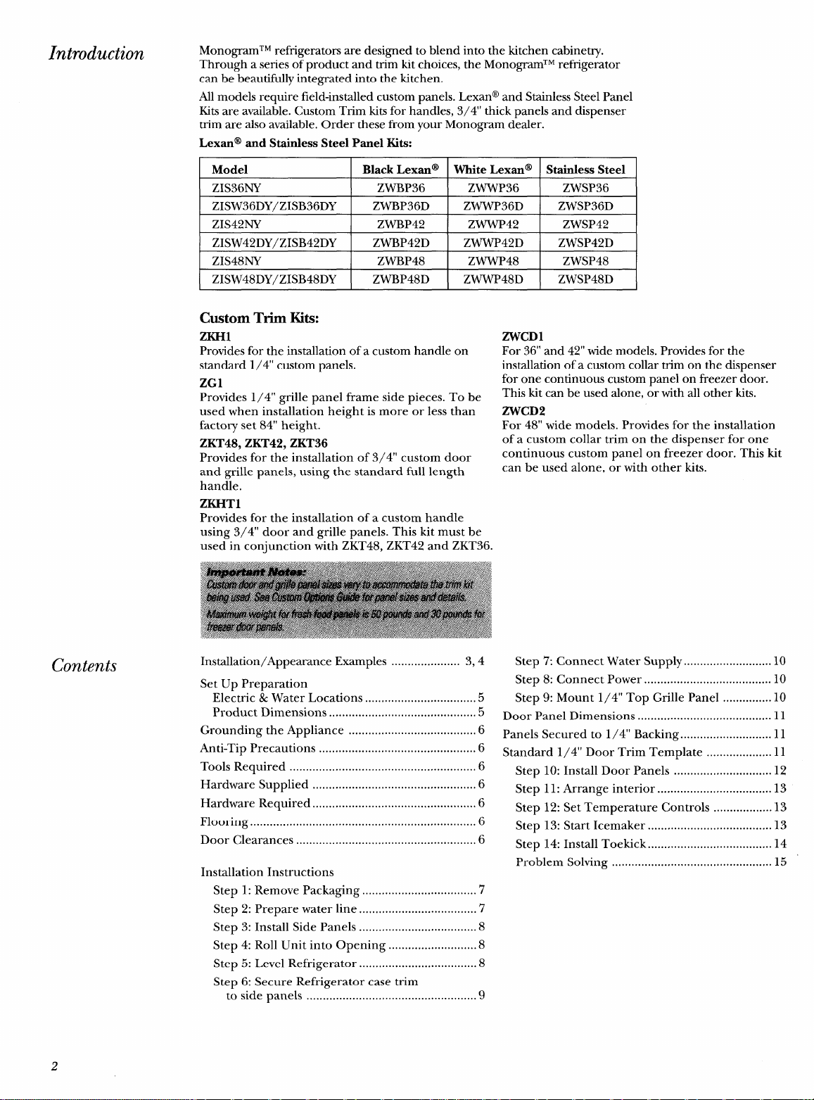
Introduction
MonogramTM refrigerators are designed to blend into the kitchen cabinetry.
Through a series of product and trim kit choices, the MonogramTM refrigerator
can be beautifully integrated into the kitchen.
All models require field-installed custom panels. Lexan@ and Stainless Steel Panel
Kits are available. Custom Trim kits for handles, 3/4” thick panels and dispenser
trim are also available. Order these from your Monogram dealer.
Lexan@
and Stainless Steel Panel Kits:
Model
Black Lexan@
White Lexan@ Stainless Steel
ZIS36NY ZWBP36
ZWWP36 ZWSP36
ZISW36DY/ZISB36DY
ZWBP36D
ZWWP36D ZWSP36D
ZIS42NY
ZWBP42 ZWWP42 ZWSP42
ZISW42DY/ZISB42DY
ZWBP42D ZWWP42D ZWSP42D
ZIS48NY
ZWBP48 ZWWP48 ZWSP48
ZISW48DY/ZISB48DY ZWBP48D
ZWWP48D ZWSP48D
Contents
Custom Trim Kits:
ZKH1
Provides for the installation of a custom handle on
standard 1/4” custom panels.
ZG1
Provides 1/4” grille panel frame side pieces. To be
used when installation height is more or less than
factory set 84” height.
ZKT48, ZKT42, ZKT36
Provides for the installation of 3/4” custom door
and grille panels, using the standard full length
handle.
ZKHT1
Provides for the installation of a custom handle
using 3/4” door and grille panels. This kit must be
used in conjunction with ZKT48, ZKT42 and ZKT36.
Installation/Appearance Examples ..................... 3,4
Set Up Preparation
Electric & Water Locations ..................................5
Product Dimensions .............................................5
Grounding the Appliance .......................................6
Anti-Tip Precautions ................................................6
Tools Required .........................................................6
Hardware Supplied ..................................................6
Hardware Required ..................................................6
Flooring ..................................................................... 6
Door Clearances .......................................................6
Installation Instructions
Step 1: Remove Packaging ...................................7
Step 2: Prepare water line ....................................’7
Step 3: Install Side Panels ....................................8
Step 4: Roll Unit into Opening ...........................8
Step 5: Level Refrigerator
....................................
8
Step 6: Secure Refrigerator case trim
to side panels ....................................................9
ZWCD1
For 36” and 42” wide models. Provides for the
installation of a custom collar trim on the dispenser
for one continuous custom panel on freezer door.
This kit can be used alone, or with all other kits.
ZWCD2
For 48” wide models. Provides for the installation
of a custom collar trim on the dispenser for one
continuous custom panel on freezer door. This kit
can be used alone, or with other kits.
Step 7: Connect Water Supply ...........................10
Step 8: Connect Power ....................................... 10
Step 9: Mount 1/4” Top Grille Panel ...............10
Door Panel Dimensions ......................................... 11
Panels Secured to 1/4” Backing ............................ 11
Standard 1/4” Door Trim Template .................... 11
Step 10: Install Door Panels .............................. 12
Step 11: Arrange interior ...................................13
Step 12: Set Temperature Controls ..................13
Step 13: Start Icemaker ......................................l3
Step 14: Install Toekick ......................................l4
Problem Solving ................................................. 15
2
Monogram’” Built-In Refrigerator
Installation/Appearance Examples
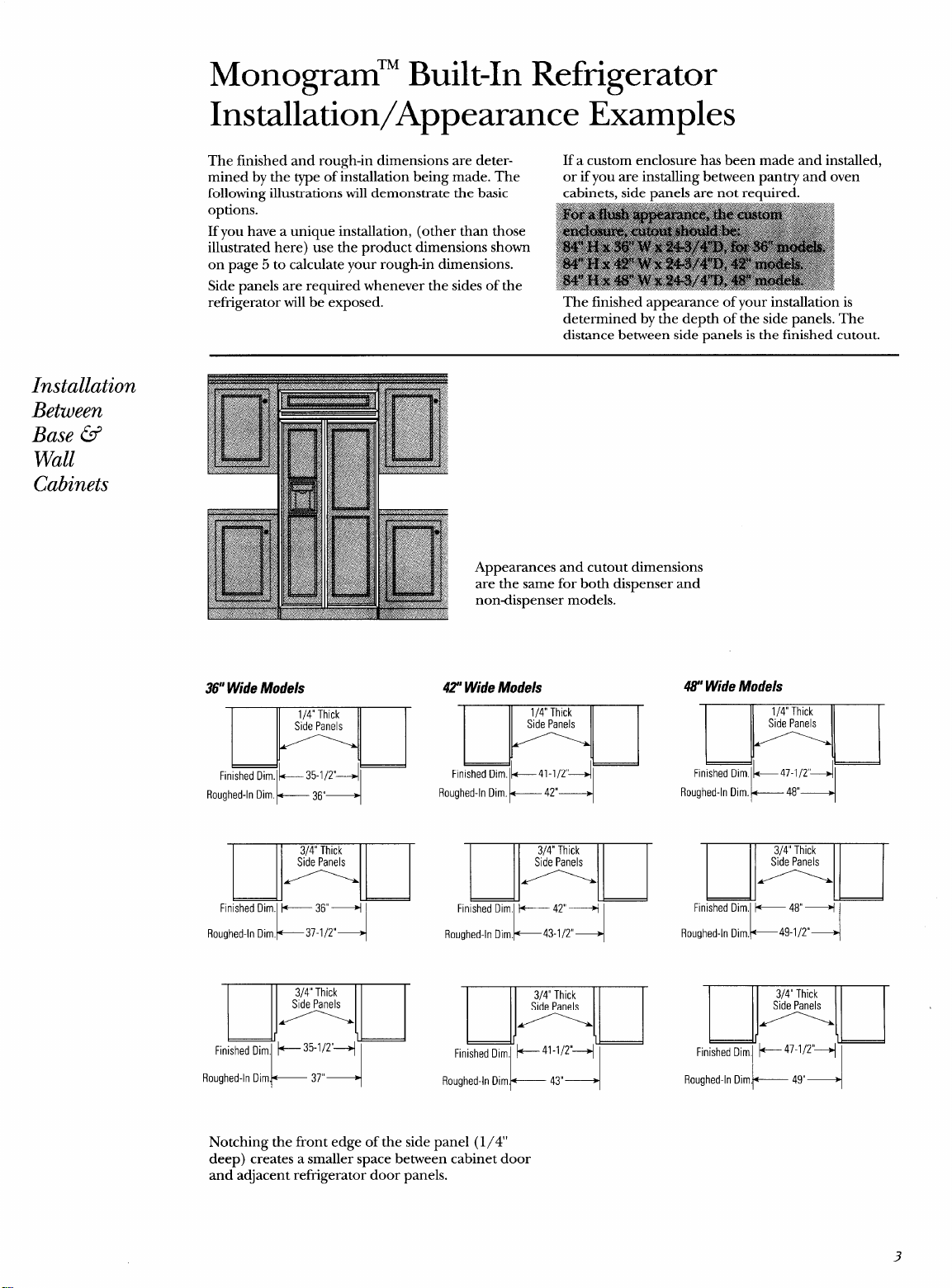
The finished and rough-in dimensions are deter-
If a custom enclosure has been made and installed,
mined by the type of installation being made. The
or if you are installing between pantry and oven
following illustrations will demonstrate the basic cabinets, side panels are not required.
refrigerator will be’ exposed. The finished appearance of your installation is
determined by the depth of the side panels. The
distance between side-panels is the finished cutout.
Installation
Between
Base @
Wall
Cabinets
36”Wide Models
Roughed-In Dim. l+----- 36”+
Appearances and cutout dimensions
are the same for both dispenser and
nondispenser models.
42”Wide Models
H ‘g
Finished DirnlL35-1/2’~1
41-1/2”
42”
Roughed-In Dim~— 37”+
Roughed-In ilim.~— 43”+
48” Wide Models
m
Finished Dim lk47-1/2’ql
Roughed-In Dim.~ 48”+
E
Finished Dim,
Roughed-In Dim.
K
+ 48”+
~49-1/2°
4
Roughed-In Diml+—————49”+
Notching the front edge of the side panel (1/4’
deep) creates a smaller space between cabinet door
and adjacent refrigerator door panels.
3
—
—
Installation
At End-ofRun
Base @ Wall
Cabinets
Installation
Between
Wall Oven
and Pantry
Cabinet
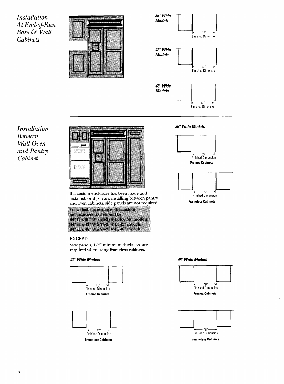
36” Wide
Models
k--
36”4
Finished Dimension
42?Wide
Models
k
47”+
Finished ~imension
47’ Wide
Models
k 48”+
Finished Dimension
If a custom enclosure has been made and
installed, or if you are installing between pantry
and oven cabinets, side panels are not required.
EXCEPT:
Side panels, 1/2” minimum thickness, are
required when using frarneless cabinets.
42” Wide Models
I
+ 47”+
Finished ~imenslon
FramedCabinets
F!nished Dimension
36” Wide Models
$
& 36”+
Finished Dimension
FramedCabinets
Finished Dimension
43” Wide Models
)
k 48”+
Finished Dimension
FramedCabinets
-.
J-
* 48”+
Finished Dimension
FramelessCabinets
FramelessCabinets
4
Monogram’” Built-In Refrigerator
Set up Preparation
Before you begin – Read these instructions completely and carefully.
IMPORTANT – Save these instructions for local inspector’s use.
IMPORTANT – OBSERVE ALL GOVERNING CODES AND ORDINANCES.
Note to Installer – Be sure to leave these instructions with the Consumer.
Note to Consumer –
Keep these instructions with your Use and Care Book for future reference.
Electric and
Water
Connection
Locations
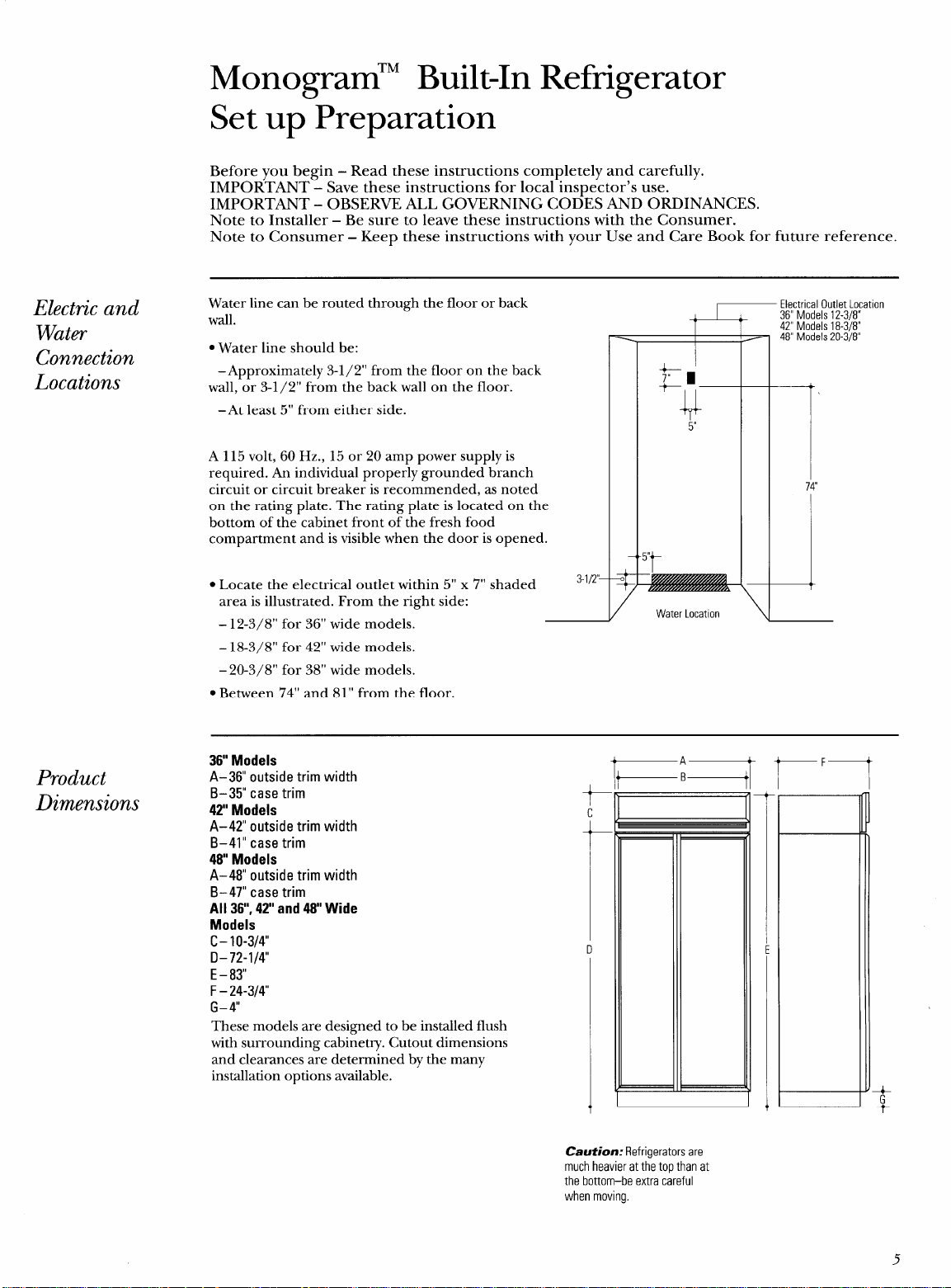
Water line can be routed through the floor or back
wall.
● Water line should be:
–Approximately 3-1/2” from the floor on the back
wall, or 3-1/2” from the back wall on the floor.
–At least 5“ from either side.
A 115 volt, 60 Hz., 15 or 20 amp power supply is
required. An individual properly grounded branch
circuit or circuit breaker is recommended, as noted
on the rating plate. The rating plate is located on the
bottom of the cabinet front of the fresh food
compartment and is visible when the door is opened.
● Locate the electrical outlet within 5“ x 7“ shaded
3-l/2’–
area is illustrated. From the right side:
– 12-3/8” for 36” wide models.
– 18-3/8” for 42” wide models.
– 20-3/8” for 38” wide models.
● Between 7’4” and 81” from the floor.
Product
Dimensions
Electrical Outlet Location
36” Models 12-3/8”
42” Models 18-3/8”
48” Models 20-3/8”
/
Water LocatIon
7
\
—
36” Models
A-36” outside trim width
B–35” case trim
42” Models
t
c
A-42” outside trim width
B–41” case trim
48 Models
A–48” outside trim width
B–47” case trim
All 36”,42” and 48 Wide
Models
c- 10-3/4”
t
.
D-72-l/4
u
E -83”
F- 24-3/4
G- 4“
These models are designed to be installed flush
with surrounding cabinetry. Cutout dimensions
and clearances a;e determined by the many
installation options available.
A
B
I
1
—
—
r
F—
Caution: Refrigerators are
much heavier at the top than at
the bottom–be extra careful
when moving.
5
—
Grounding the
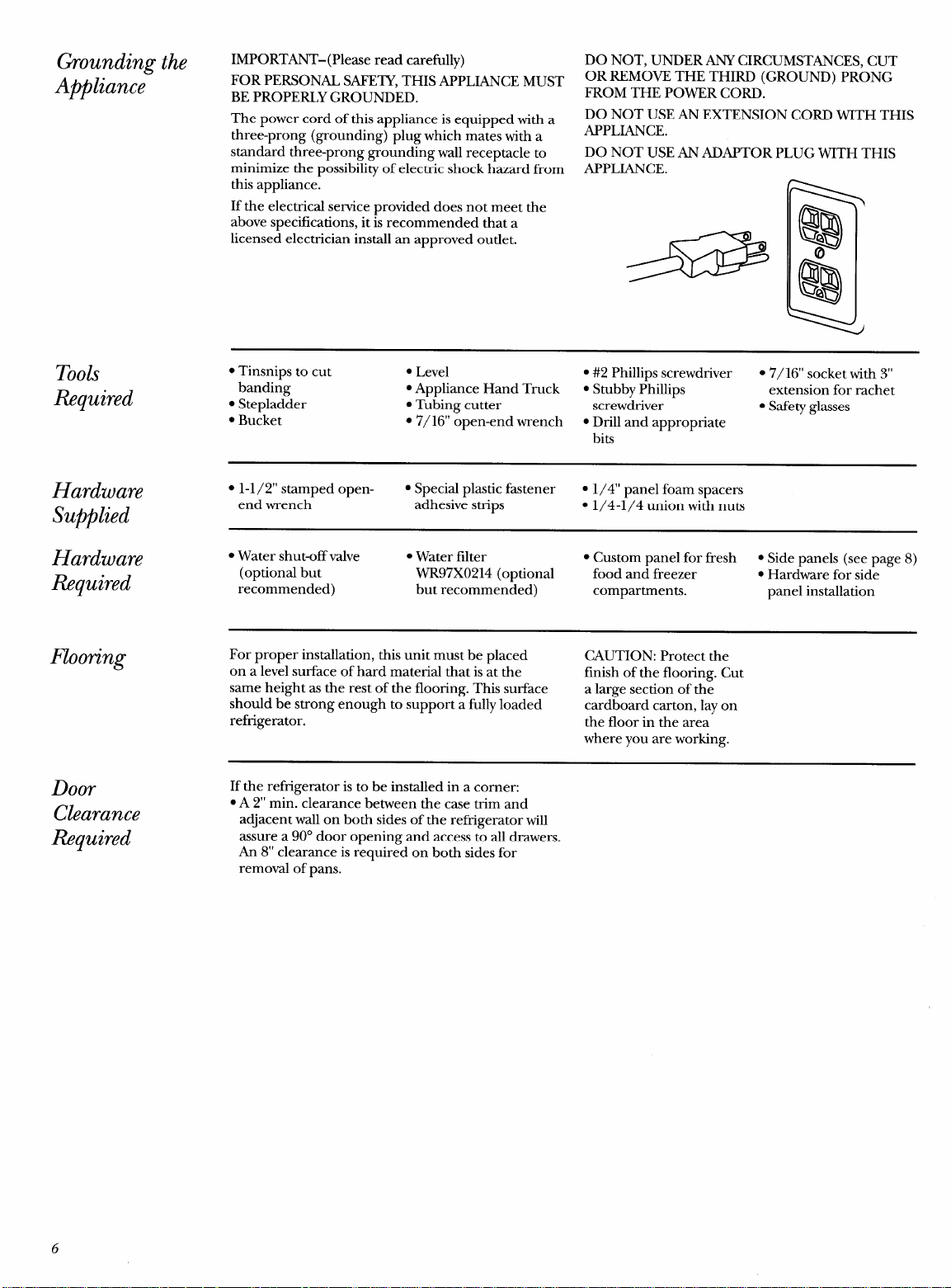
IMPORTANT-( Please read carefully)
Appliance
FOR PERSONAL SAFETY, THIS APPLIANCE MUST
BE PROPERLY GROUNDED.
The power cord of this appliance is equipped with a
three-prong (grounding) plug which mates with a
standard three-prong grounding wall receptacle to
minimize the possibility of electric shock hazard from
this appliance.
If the electrical service provided does not meet the
above specifications, it is recommended that a
licensed electrician install an approved outlet.
DO NOT, UNDER ANY CIRCUMSTANCES, CUT
OR REMOVE THE THIRD (GROUND) PRONG
FROM THE POWER CORD.
DO NOT USE AN EXTENSION CORD WITH THIS
APPLIANCE.
DO NOT USE AN ADAPTOR PLUG WITH THIS
APPLIANCE.
Tools
Required
● Tinsnips to cut
● Level
● #2 Phillips screwdriver
● 7/16” socket with 3“
banding
“ Appliance Hand Truck
● Stubby Phillips
extension for rachet
● Stepladder
. Tubing cutter
screwdriver
● Safety glasses
c Bucket
● 7/16” open-end wrench
● Drill and appropriate
bits
Hardware
s
1-1/2” stamped open-
. Special plastic fastener
● 1/4” panel foam spacers
Supplied
end wrench
adhesive strips
. 1/4-1/4 union with nuts
Hardware
● Water shut-off valve ● Water filter
● Custom panel for fresh ● Side panels (see page 8)
Required
(optional but WR97X0214 (optional
food and freezer
● Hardware for side
recommended)
but recommended)
compartments.
panel installation
Flooring
For proper installation, this unit must be placed
CAUTION: Protect the
on a level surface of hard material that is at the
finish of the flooring. Cut
same height as the rest of the flooring. This surface
a large section of the
should be strong enough to support a fully loaded
cardboard carton, lay on
refrigerator.
the floor in the area
where you are working.
Door
Clearance
Ii%quired
If the refrigerator is to be installed in a corner:
● A 2“ min. clearance between the case trim and
adjacent wall on both sides of the refrigerator will
assure a 90° door opening and access to all drawers.
An 8“ clearance is required on both sides for
removal of pans.
6
1
Step
Remove
Packaging
2
Step
Prepare
Water
Line
Built-In Refrigerator Installation Steps
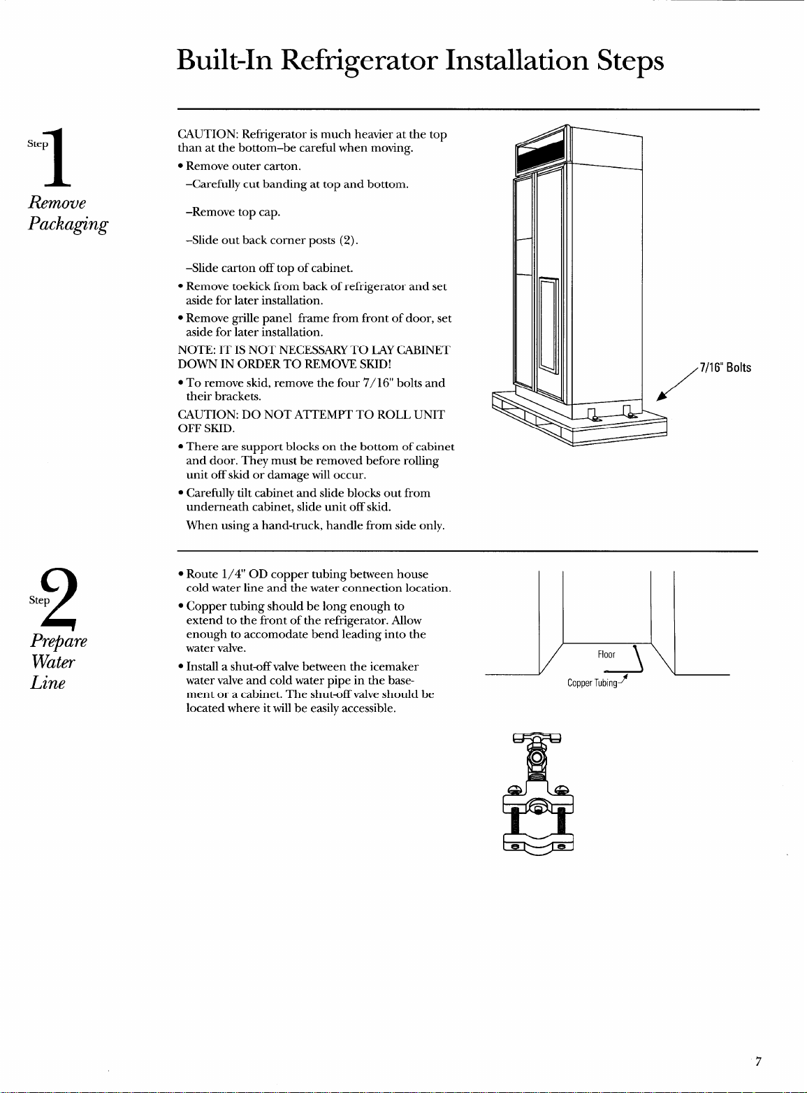
CAUTION: Refrigerator is much heavier at the top
than at the bottom–be careful when moving.
● Remove outer carton.
–Carefully cut banding at top and bottom.
–Remove top cap.
-Slide out back corner posts (2).
–Slide carton off top of cabinet.
● Remove toekick from back of refi-igerator and set
aside for later installation.
s Remove grille panel frame from front of door, set
aside for later installation.
NOTE: IT IS NOT NECESSARY TO LAY CABINET
DOWN IN ORDER TO REMOVE SKID!
. To remove skid, remove the four 7/ 16“ bolts and
their brackets.
CAUTION: DO NOT ATTEMPT TO ROLL UNIT
OFF SKID.
c There are support blocks on the bottom of cabinet
and door. They must be removed before rolling
unit off skid or damage will occur.
● Carefully tilt cabinet and slide blocks out from
underneath cabinet, slide unit off skid.
When using a hand-truck, handle from side only.
/
7/1 6“ Bolts
s Route 1/4” OD copper tubing between house
cold water line and the water connection location.
● Copper tubing should be long enough to
extend to the front of the refi-igerator. Allow
enough to accommodate bend leading into the
water valve.
. Install a shut-off valve between the icemaker
water valve and cold water pipe in the base-
ment or a cabinet. The shutoff valve should be
located where it will be easily accessible.
l\
Floor
Copper Tubmgy
&
o
7
——.
3
Step
Install
Side
Panels
4
Step
Roll Unit
into Opening
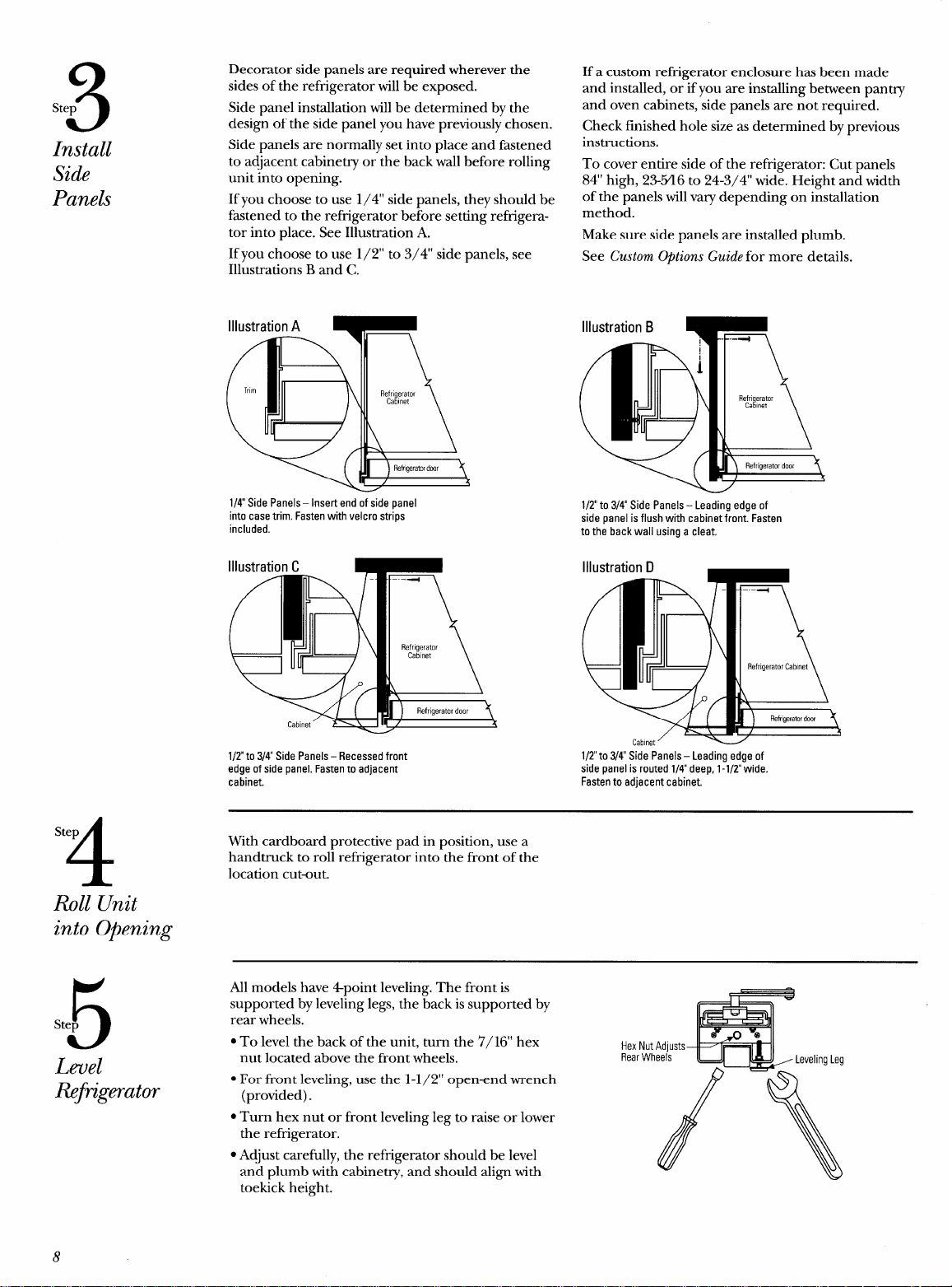
Decorator side panels are required wherever the
sides of the refi-igerator will be exposed.
Side panel installation will be determined by the
design of the side panel you have previously chosen.
Side panels are normally set into place and fastened
to adjacent cabinetry or the back wall before rolling
unit into opening.
If you choose to use 1/4” side panels, they should be
fhstened to the refrigerator before setting refrigera-
tor into place. See Illustration A.
If you choose to use 1/2” to 3/4” side panels, see
Illustrations B and C.
1/4 Side Panels – Insert end of side panel
into case trim. Fasten with velcro strips
included.
Illustration C
l/Z”to 3/4 Side Panels – Recessed front
edge of side panel. Fasten to adjacent
cabinet.
If a custom refi-igerator enclosure has been made
and installed, or if you are installing between pantry
and oven cabinets, side panels are not required.
Check finished hole size as determined by previous
instructions.
To cover entire side of the refrigerator: Cut panels
84” high, 23-Y16 to 24-3/4” wide. Height and width
of the panels will vary depending on installation
method.
Make sure side panels are installed plumb.
See Custom Options Guide for more details.
1/2 to 3/4” Side Panels – Leading edge of
side panel is flush with cabinet front. Fasten
to the back wall using a cleat.
Cabinet’
1/2to 3/4 Side Panels – Leading edge of
side panel is routed 1/4 deep, 1-1/2 wide.
Fasten to adjacent cabinet.
With cardboard protective pad in position, use a
handtruck to roll refrigerator into the front of the
location cutout.
5
Step
Level
fiftigerator
All models have 4point leveling. The front is
supported by leveling legs, the back is supported by
rear wheels.
● To level the back of the unit, turn the 7/16” hex
Hex Nut
nut located above the front wheels,
Rear Wh
● For front leveling, use the 1-1/2” open-end wrench
(provided).
. Turn hex nut or front leveling leg to raise or lower
the refrigerator.
. Adjust carefully, the refrigerator should be level
and plumb with cabinetry, and should align with
toekick height.
8
Step
6
Anti-Tip
Secure
Precautions
R@k&rator
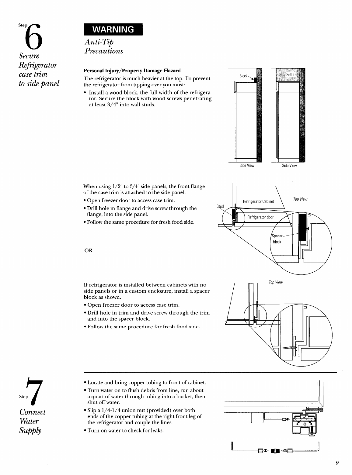
Personal Injury/Property Damage Hazard
case tn”m
The refi-igerator is much heavier at the top. To prevent
to sidepanel
the refrigerator from tipping over you mus~
● Install a wood block, the full width of the refrigera-
tor. Secure the block with wood screws penetrating
at least 3/4” into wall studs.
7
Step
Connect
Water
Supplj
When using 1/2” to 3/4” side panels, the front flange
of the case trim is attached to the side panel.
s Open freezer door to access case trim.
● Drill hole in flange and drive screw through the
flange, into the side panel.
● Follow the same procedure for fresh food side.
—
Side View
Stud
\ /
/
—
—
Side View
OR
If refrigerator is installed between cabinets with no
side panels or in a custom enclosure, install a spacer
block as shown.
● Open freezer door to access case trim.
● Drill hole in trim and drive screw through the trim
and into the spacer block.
● Follow the same procedure for fresh food side.
● Locate and bring copper tubing to front of cabinet.
● Turn water on to flush debris from line, run about
a quart of water through tubing into a bucket, then
shut off water.
\
1’
● Slip a 1/4-1/4 union nut (provided) over both
t--l
IJ
ends of the copper tubing at the right front leg of
~
the refrigerator and couple the lines.
. Turn on water to check for leaks.
L..
!I
9
-—
8
Ste
Connect
Power
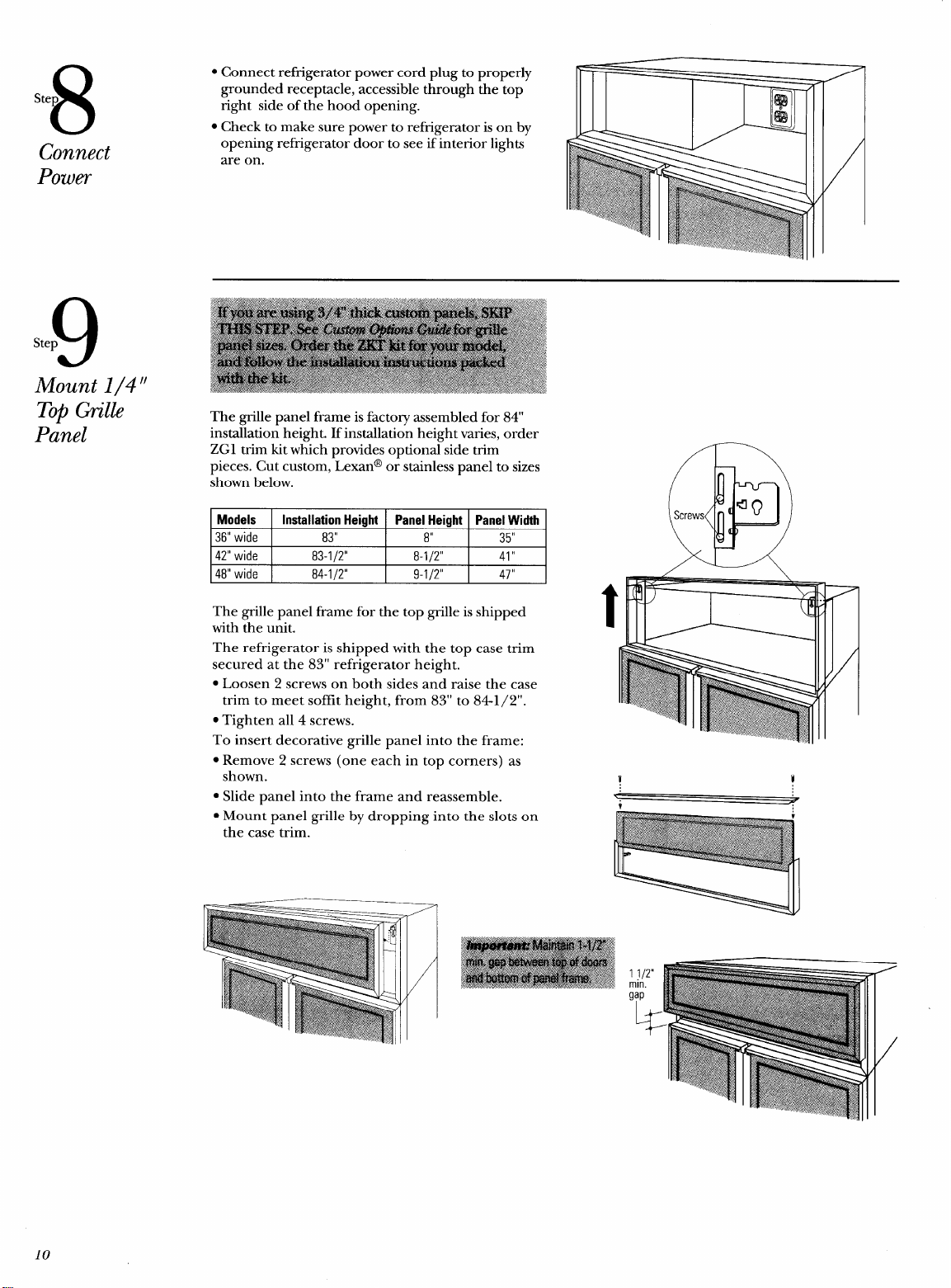
The grille panel frame for the top grille is shipped
with the unit.
The refrigerator is shipped with the top case trim
secured at the 83” refrigerator height.
. Loosen 2 screws on both sides and raise the case
trim to meet soffit height, from 83” to 841/2”.
. Tighten all 4 screws.
To insert decorative grille panel into the frame:
s Remove 2 screws (one each in top corners) as
shown.
● Slide panel into the frame and reassemble.
● Mount panel grille by dropping into the slots on
the case trim.
1 1/2”
min.
g;p
10
Door
Panel
Dimensions
Panels
Secured
to 1/4‘f
Backing
Standard
1/4“Door
Trim
Template
All models require field-installed panels. Lexan@ and
stainless steel panel kits are sized to fit your model. If
you are using custom panels, cut the panels to the
sizes shown for your model.
1/4” CUSTOM PANEL DIMENSIONS
Model Non-Dispenser
Dispenser Freezer Panel
Fresh Food
Freezer Panel
(WXH) Panel
(WXH)
lher Lower
(WXH)
I
ZIS36NY
I
15-1
/4’’x67-7/8°
I I I
19-1
/4’’x67-7/8°
I
ZISW36DY
I
I
15-1/4”xl 6-5/8”
I
15-1
/4’’x36-7/8°
I
19-1/4’’x67-7/8°
ZISB36DY
ZIS42NY 15-1j4’’x67-7/8° 25-1 /4’’x67-7/8°
ZISW42DY
15-1/4”xl 6-5/8” 15-1/4’1x36-7/8° 25-1 /4’’x67-7/8°
ZISB42DY
ZIS48NY 19-114’’x67-7I8° 27-1 14’’x67-7I8°
I
ZISW48DY
I
I
19-1/4”xl
6-5/8”
I
19-1/4’’x36-7/8°
I
27-1 /4’’x67-7/8°
ZISB48DY
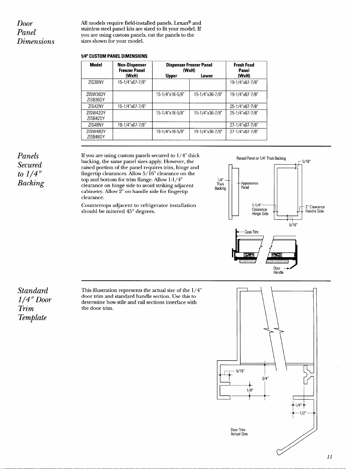
If you are using custom panels secured to 1/4” thick
backing, the same panel sizes apply. However, the
raised portion of the panel requires trim, hinge and
fingertip clearances. Allow 5/16’ clearance on the
top and bottom for trim flange. Allow 1-1/4”
clearance on hinge side to avoid striking adjacent
cabinetry. Allow 2“ on handle side for fingertip
clearance.
Countertops adjacent to refrigerator installation
should be mitered 45° degrees.
RaisedPanelon 1/4” Thick Backing
r 5/16“
1/4
Thick
B
1 .; L ~
Appearance
Backing
Panel
1-1/4”
Clearance
2“ Clearance
Hinge Side
Handle Side
5/16“
Handle
This illustration represents the actual size of the 1/4”
door trim and standard handle section. Use this to
determine how stile and rail sections interface with
the door trim.
+““
1/4”
Door Trim
Actual Size
t
1/2”
1
11
10
Step
Install 1/4”
Door Panels
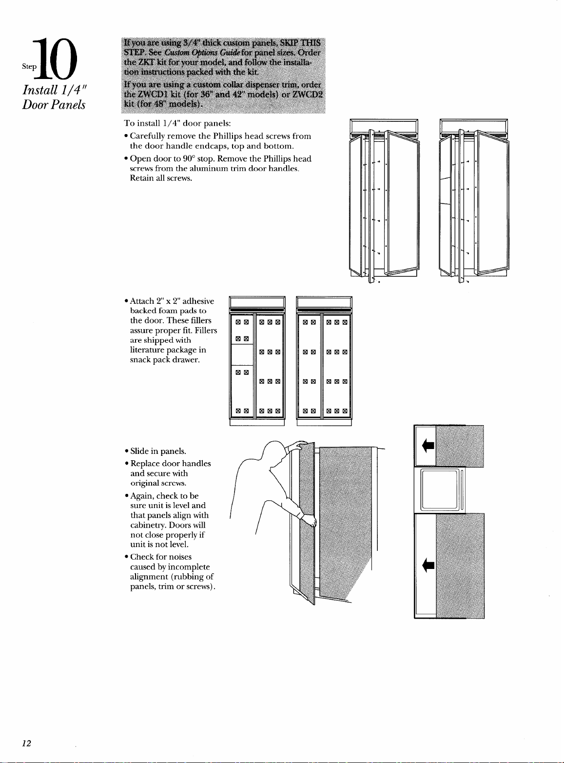
To install 1/4” door panels:
. Carefully remove the Phillips head screws from
the door handle endcaps, top and bottom.
● Open door to 90° stop. Remove the Phillips head
screws from the aluminum trim door handles.
Retain all screws.
c Attach 2“ x 2“ adhesive
backed foam pads to
the door. These fillers
assure proper fit. Fillers
are shipped with
literature package in
snack pack drawer.
c Slide in panels.
● Replace door handles
and secure with
original screws.
● Again, check to be
sure unit is level and
that panels align with
cabinetry. Doors will
not close properly if
unit is not level.
● Check for noises
caused by incomplete
alignment (rubbing of
panels, trim or screws).
L I
12
11
step
Arrange
Interior
12
Step
set
Temperature
Controls
13
Step
Start
Icemaker
n
11
v
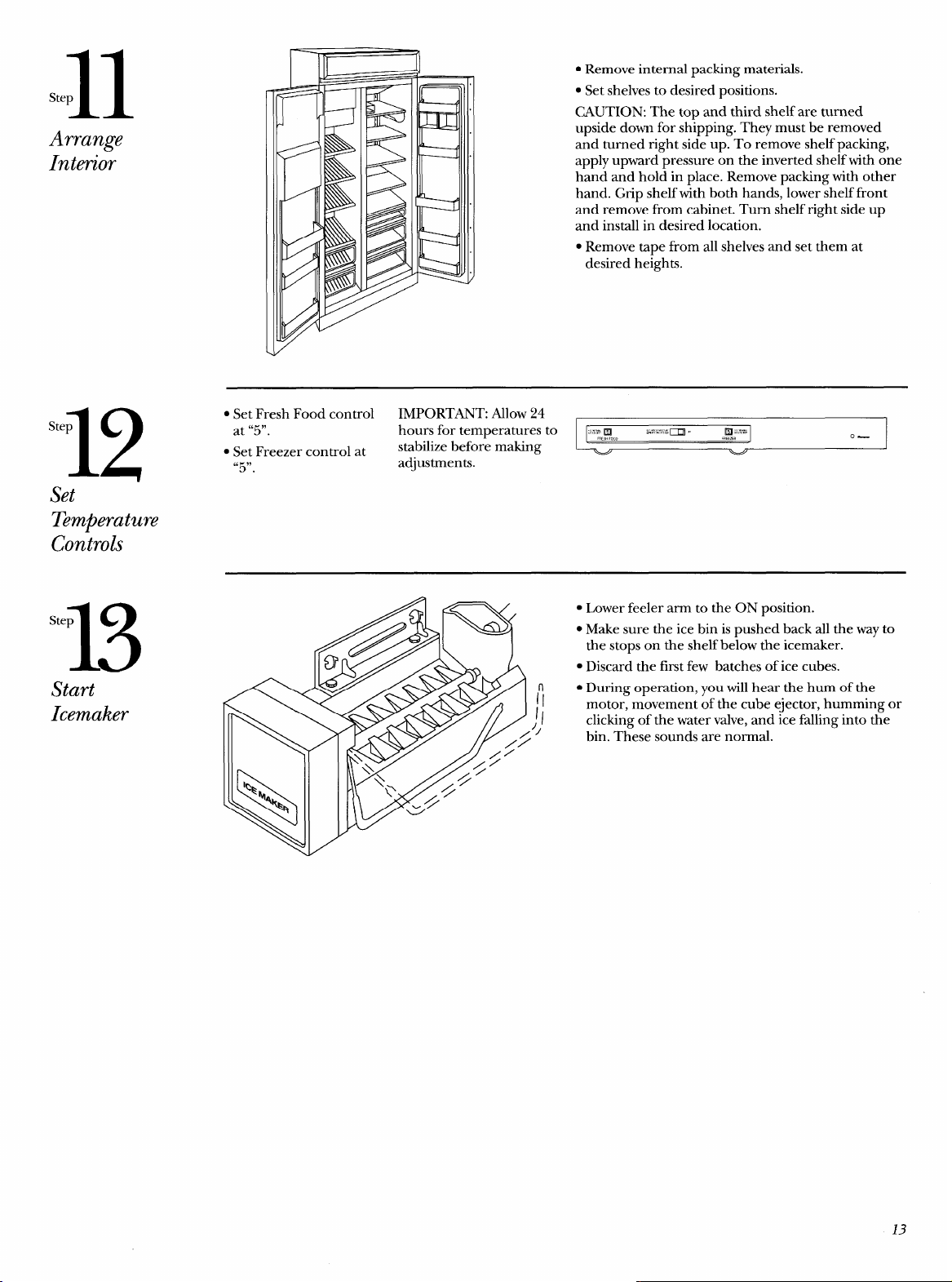
● Remove internal packing materials.
. Set shelves to desired positions.
CAUTION: The top and third shelf are turned
upside down for shipping. They must be removed
and turned right side up. To remove shelf packing,
apply upward pressure on the inverted shelf with one
hand and hold in place. Remove packing with other
hand. Grip shelf with both hands, lower shelf front
and remove from cabinet. Turn shelf right side up
and install in desired location.
c Remove tape from all shelves and set them at
desired heights.
. Set Fresh Food control
IMPORTANT: ~low 24
at “5”.
hours for temperatures to
~z:,gooo
&?~!?~i
m , ,Rg;=
stabilize before making
0—
● Set Freezer control at
“5”.
adjustments.
● Lower feeler arm to the ON position.
. Make sure the ice bin is pushed back all the way to
the stops on the shelf below the icemaker.
● Discard the first few batches of ice cubes.
● During operation, you will hear the hum of the
II
1/
motor, movement of the cube ejector, humming or
clicking of the water valve, and ice falling into the
11
bin. These sounds are normal.
13
14
Step
Install
Toekick
Standard Non-Dispenser Model Toekick (Packed with product)
t’ rl
Standard Dispenser Model Toekick (Packed with Product)
f fl
1/4” Thick Custom Dispenser Model Toekick
3-1/4
I f A
1 1 1
II
I
v
1/2” to 3/4” Thick Custom Dispenser Toekick
Remove Additional Material
+44/16+
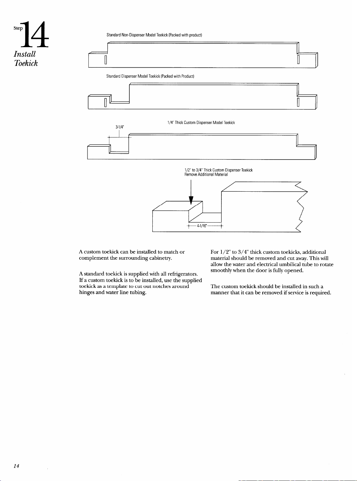
A custom toekick can be installed to match or
For 1/2” to 3/4” thick custom toekicks, additional
complement the surrounding cabinetry.
material should be removed and cut away. This will
allow the water and electrical umbilical tube to rotate
A standard toekick is supplied with all refi-igerators.
smoothly when the door is fully opened.
If a custom toekick is to-be installed, use th~ supplied
toekick as a template to cut out notches around
The custom toekick should be installed in such a
hinges and water line tubing.
manner that it can be removed if service is required.
14
.-—
Problem
Solving
Alignment of Doors
Door alignment is usually
assured when the
unit is
leveled. If doors are not
aligned after leveling the
unit, contact GE Service.
Moisture
If moisture forms
between the doors or on
the cabinet, turn on the
energy saver switch. This
should only occur when
humidity is high. If the
problem persists, contact
GE Service.
Operation of Unit
If the
refrigerator does
not operate after
checking the installation
instructions, check the
electrical connections
inside the cooling
compartment, check the
power cord plug in the
wall outlet and the
power supply to the
outlet. If all connections
and fuse or circuit
breaker are in order,
contact GE service.
Decorator Panels
Contact
your
Contractor/Installer
Squareness of
Cabinetq
Contact your
Contractor/Installer
Water
Contact your plumber
Note: While performing installations described in this
book, safetyglasses or goggles should be worn.
To obtain specz~icinformation conce-rning any Monogram
product or seruice, call GE Answer Cent@ consumer
information service at 800.626. 2000–any time, day or
night.
For local service in your area, call 1-800-GE-CARES
(1-800-432-2737).
Note: Product improvement is a continuing endeavor at
General Electric. Therefore, materials, appearance and
specifications are subject to change without notice.
15
.— —
.-
—

Monogram.TM
Pub. No. 31-45243
Dw& No. 162D9267PO02
@1996 GE Appliances
Printed in U.S.A. (N.D. 393)
General Hectric Company
Louisville,KY40225
8823

