Loading ...
Loading ...
Loading ...
24
Replacing the Pilot/Thermopile Assembly
1. Remove the manifold assembly as directed previously.
2.
Lift the retainer clip straight up from the back of
the manifold component block (using a flat-blade
screwdriver), then remove the manifold component
block from the manifold door
(Figure 25).
3. Locate and remove the screws on the underside of the
burner, then remove the burner. IMPORTANT: DO NOT
remove the orifice. LP Cast Burner models DO NOT
require the burner to be removed. Remove the screw
securing the pilot assembly to the manifold.
NOTE: For cast burner models, remove the screw securing
the pilot assembly to the burner.
4. Using a 7/16” wrench, loosen the nut securing the pilot
tube to the pilot assembly.
NOTE: To prevent any bending of the pilot bracket, use
pliers to hold the pilot assembly bracket while loosening the
pilot nut.
5.
Disconnect the red wire connected to the thermal switch,
then lift the pilot/thermopile assembly (including the igniter
wire) from the manifold assembly.
6. Pull the pilot tube from the pilot assembly (Figure 26).
IMPORTANT: Be careful not to bend or alter the position of
the pilot assembly components.
7.
Using the old pilot/pilot tube assembly as a guide, bend
the new pilot tube to match the old one. Make only the
bends closest to the pilot before going to the next step.
8. Push the new pilot assembly connectors through the hole
in the manifold door (See Figure 25). Reconnect the pilot
tube and tighten the nut securing it to the pilot assembly.
IMPORTANT: Keep the pilot orifice in the pilot when
making the connection. DO NOT operate the water
heater without the pilot orifice installed. Reattach the pilot
assembly to the manifold. Cast burner models reattach the
pilot assembly to the burner.
9. Reattach the burner and secure with screws.
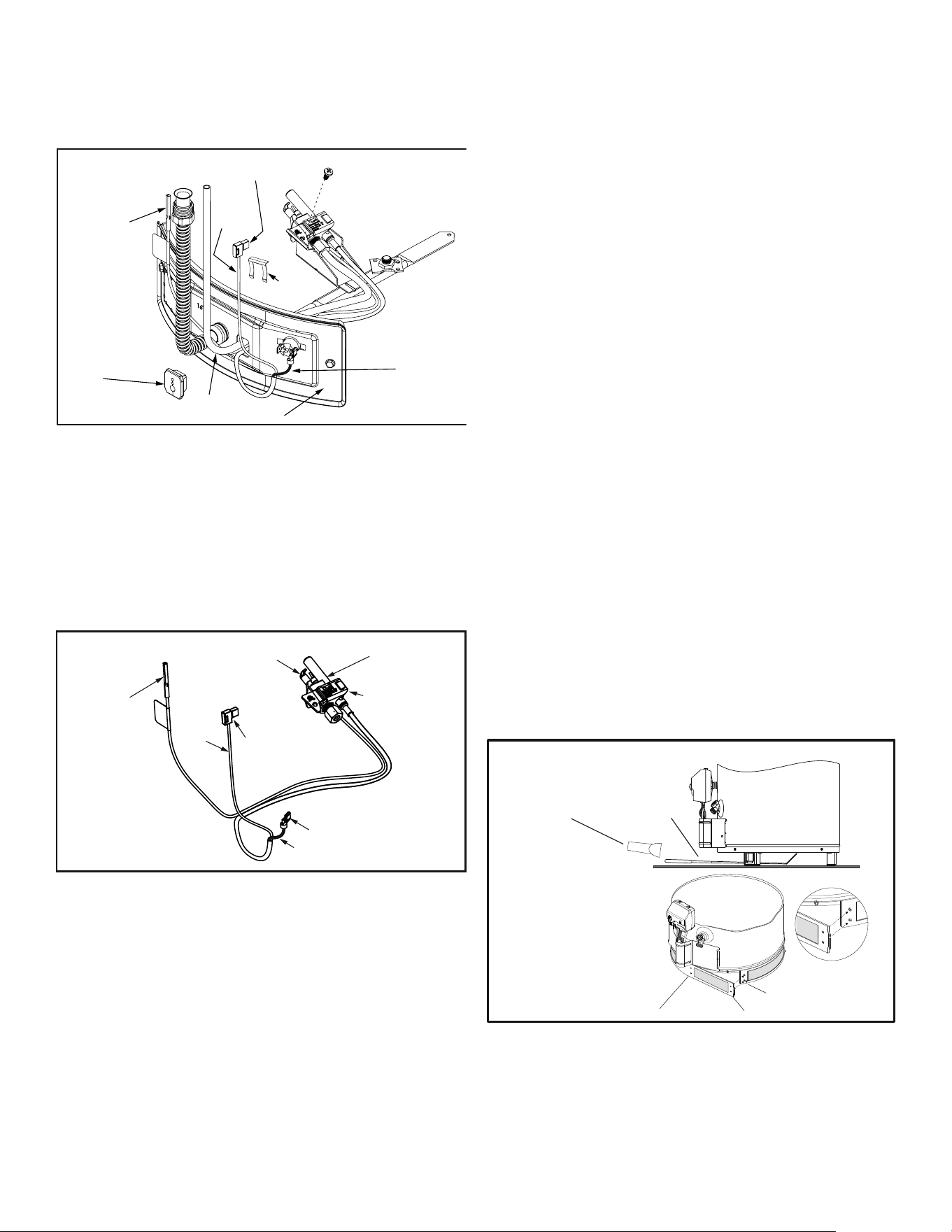
Figure 25
Manifold Component
Block Assembly
Thermopile
Connector
Manifold Component
Block
Pilot Tube
Igniter
Wire
Burner and other
fittings not show
for clarity.
Manifold Door
White
Wire
Red
Wire
Retainer
Clip
Figure 26
Pilot/Thermopile Assembly
Pilot/Thermopile
Assembly
Igniter
Connector
Thermal
Switch
Connectors
Pilot
Thermopile
Thermopile
Connector
White
Wire
Red
Wire
NOTE: See figure 24A for correct burner orientation.
10. Position the new thermopile wires through the top opening
of the manifold component block (Figure 25). Be sure the
igniter wire is positioned through the middle opening of
the manifold component block.
11. See “Replacing Manifold Assembly” Page 25.
Filter Installation and Cleaning
IMPORTANT: It is essential that the fi lter be installed properly.
If you encounter diffi culty installing the fi lter or have a question,
please call the Service & Warranty Department listed on the cover
of your manual.
Filter Installation
1. Before attaching the filter, remove any dust or debris that
may have accumulated in the installation area. It is also
recommended that a visual inspection of the flame-trap be
performed. Refer to the “External Inspection & Cleaning of
the Flame-trap” section.
2. Connect the end points of the filter sections together (see
Figure 27) to form one long section. Wrap this section
around the base of the water heater and join at the
closest connection point to fit your water heater. NOTE:
If your water heater has a small diameter tank it may be
necessary to use both inner connection points).
3. Once connected, check to ensure a close fit with no gaps
between the water heater, the filter, and the floor
(see Figure 27). NOTE: Depending on the size of your
water heater, the filter may have some excess material.
This may be trimmed away.
4. It is recommended that the filter be inspected periodically
to maintain unrestricted airflow to the water heater.
Periodic Cleaning of the Filter
1. If periodic inspection of the filter shows a build-up on the filter,
it should be removed and cleaned.
2. To remove the filter, locate a set of connection posts (see
Figure 27) and squeeze them together while pulling outward
on the thumb tab.
3. The filter can then be vacuumed to remove the build-up.
4. Before re-attaching the filter, a visual inspection of the flame-
trap is recommended. Refer to the “External Inspection &
Cleaning of the Flame-trap” section.
5. Follow Filter Installation instructions 2-3 to re-attach the filter.
Figure 27
Flame-trap visual inspection
filter installation/removal
&
Mirror
Inner Connection Points
Outer Connection Points
Connection Posts
Flashlight
External Inspection & Cleaning of the
Flame-trap
Although not likely to occur, if debris collects on the flame-
trap, use a vacuum, compressed air, or a soft bristle brush
to remove it.
NOTE: If unable to inspect or clean the flame trap from
underneath, follow the “Cleaning the Combustion Chamber
and Flame-trap” section instructions.
Loading ...
Loading ...
Loading ...