
SafetyInstructions& Operator'sManual for
21" STEELDECK
WALKMOWERS
SERIES19
f
Models
RP2167519BD V (7800066)
RP2187519BV (7800172)
RP2187519BVE (7800173)
RP216019KWV (7800199)
2167519B
P2167519B
P2187519BV
P2187519BVE
P216019KWV
N2167519B
(7800217)
(7800218)
(7800176)
(7800178)
(7800193)
(7800133)
NP2167519B(7800134)
NP2187519BV (7800131)
J
NOTE:Specifications are correct at time of printing and are subjectto changewithout notice.
* Actualsustained engine power will likely he lower due to operating limitations and environmental factors. Please refer to 'Engine Power Rating Information' for
further details.
Manual No. 7101587 (I.R. 9/25/2007)
TP lO0-5289-1R-WB-N

ThankYoufor purchasingthis quality-built Snapper product. We're pleasedthat you placedyour
confidence in the Snapper brand. When operatedand maintained according to the instructions in this
manual, your Snapper product will provide many years of dependableservice.
This manual containssafety information to makeyou awareof the hazardsand risks associatedwith the
machine and how to avoid them. This machine is designed and intended only for finish cutting of
established lawns and is not intendedfor any other purpose. It is important that you read and understand
these instructions thoroughly before attempting to start or operatethis equipment. Savethese
instructions for future reference.
PRODUCT REGISTRATION
IMPORTANT: KEEPTHIS INFORMATION FOR YOUR PERSONAL RECORDS
(Complete the following information on your Snapper purchase)
Date of Purchase
Retailer
Retailer's Phone Number
Equipment
Model Number
Serial Number
Engine
Model .Type. Trim
It is very importantthat youregisteryourpurchasewith Snapperto ensurewarrantycoverage.Please
mail yourproductregistrationcardto:
Snapper at P.O. Box 777, McDonough, Georgia 30253.
Or you may registeronline at www.snapper.com.
Youcan contactusat our website, or if you wouldlike to speakwith a CustomerService
Representative,call usat the SnapperCustomerRelationsCenterat 1-800-935-2967. Forfaster
serviceplease haveyourSerial Numberand Model Numberavailable.
SNAPPERis a trademarkof
Simplicity Manufacturing,Inc.
PortWashington,WI, USA.
Briggs& StrattonYard Power Products Group
Copyright© 2007, Briggs& StrattonCorporation
Milwaukee, WI, USA. All RightsReserved.

Tableof Contents
Operator Safety ................................................ 2
Important Operator Safety Instructions .................................. 2
Featuresand Controls ........................................... 4
Operation .................................................... 5
Pre-Start Checklist .................................................. 5
Starting & Stopping Engine & Blades .................................... 5
Propelling Mower ................................................... 6
Handle Height Adjustment ............................................ 6
Cutting Height Adjustment ............................................ 7
Recycling Operation ................................................. 7
Removing the Recycling Cover ......................................... 7
Installing the Discharge Deflector ....................................... 8
Installing the Grass Bag Adapter ........................................ 8
Installing the Grass Bag .............................................. 9
Maintenance ................................................. 10
ChangeEngine Oil .................................................. 10
CheckTransmission Grease .......................................... 10
Check Mower Blade ................................................ 11
Check Engine Drive Belt ............................................. 11
CheckTransmission Belt ............................................. 11
Service - Periodic .................................................. 11
Engine ........................................................... 11
Air Filter ......................................................... 11
Engine Oil ........................................................ 11
Storage Procedure ................................................. 11
Mower Blade Replacement ........................................... 12
BladeSharpening .................................................. 12
Wheel DriveControl Adjustment ....................................... 13
Driven and Drive Disc Service ......................................... 14
Belt Service ....................................................... 17
Engine Drive Belt Replacement ........................................ 17
Transmission Belt Replacement ....................................... 18
Battery Service .................................................... 19
Service Schedule ................................................... 20
Troubleshooting............................................... 21
Warranty .................................................... 22
WARNING
Battery posts, terminals and related accessoriescontain
lead and lead compounds, chemicals known to the State of
Californiato cause cancer and birth defects or other
reproductive harm. Wash hands after handling.
WARNING
Engineexhaust, some of its constituents, and certain
vehicle components contain or emit chemicals known to
the State of California to cause cancer or other reproductive
harm.
CD
"11
CD
CD
t_
,-1
t_
CD
mo
,-1
CD
,-1
,-1
CD
,..z.
--z
CD
t_

x,.,
,A
ImportantOperatorSafetyInstructions
WARNING:This powerful cutting machine is capable of amputating hands and feet and can throw objects
that can cause injury and damage! Failureto comply with the following SAFETYinstructions could result in
serious injury or death to the operator or other persons. The owner of the machine must understand these
instructions and must allow only persons who understand these instructions to operate machine. Each
person operating the machine must be of sound mind and body and must not be under the influence of any
substance,which might impair vision, dexterity or judgment. If you have any questions pertaining to your
machinewhich your dealer cannot answer to your satisfaction, call or write the Customer Service
Departmentat SNAPPER,IVIcDonough,Georgia 30253. Phone: (1-800-935-2967).
Protection for Children
Tragic accidents can occur if the operator is not alert to the
presenceof children. Children are often attracted to the
machine andthe mowing activity. Never assume that
children will remain where you last saw them.
1. KEEPchildren out of the mowing area and under the
watchful care of a responsible adult other than the operator.
2. DO NOT allow children in yard when machine is operated
andturn machine OFFif anyone enters the area.
3. DO NOT allow pre-teenagechildren to operate machine.
4. ALLOW only responsible adults & teenagerswith mature
judgment under close adult supervision to operate machine.
5. DO NOT pull mower backwards unless absolutely
necessary.LOOKand SEEbehind and down for children,
pets and hazards before and while backing.
6. USEEXTRACAREwhen approaching blind corners,
shrubs, trees, or other objects that may obscure vision.
SlopeOperation
1. Slopes are a major factor relatedto slip and fall acci-
dents, which can result in severe injury. All slopes require
extra caution. If you feel uneasyon a slope, DO NOT mow
it.
2. Mow across slopes, never up-and-down. Exercise
extreme CAUTIONwhen changing directions on slopes. DO
NOTmow steep slopes or other areas where stability or
traction is in doubt. Referto the Slope Guide at the end of
this manual.
3. Useextra care with grass catchers or other attachments;
these affect the handling and the stability of the machine.
Preparation
1. Read,understand, and follow instructions and warnings
in this manual and on the mower, engine and attachments.
Know the controls and the proper use of the mower before
starting.
2. Only mature, responsible persons shall operate the
machine and only after proper instruction.
3. Data indicates that operators age 60 and above, are
involved in a large percentageof mower-related injuries.
Theseoperators should evaluatetheir ability to operate the
mower safely enough to protect themselves and others
from serious injury.
Preparation
(ContinuedFrom Previous Column)
4. Handle fuel with extra care. Fuels are flammable and
vapors are explosive. Useonly an approved fuel container.
DO NOT remove fuel cap or addfuel with engine running.
Add fuel outdoors only with engine stopped and cool. Clean
spilled fuel and oil from machine. DO NOTsmoke.
5. Checkthe areato be mowed and remove all objects such
as toys, wire, rocks, limbs and other objects that could
cause injury if thrown by blade or interfere with mowing.
Also note the location of holes, stumps, and other possible
hazards.
6. Keep people and pets out of the mowing area.
Immediately,STOP Blade,Stop engine and Stop mower if
anyone entersthe area.
7. Checkshields, deflectors, switches, blade controls and
other safety devices frequently for proper operation and
location.
8. Make sure all safety decals are clearly legible. Replace if
damaged.
9. Protect yourself when mowing and wear safety glasses, a
dust mask, long pants, and substantial footwear. DO NOT
mow barefooted or with sandals.
10. Know how to STOPbladeand engine quickly in
preparation for emergencies.
11. Use extra care when loading or unloading the machine
into a trailer or truck.
12. Checkgrass catcher components frequently for signs of
wear or deterioration and replaceas neededto prevent
injury from thrown objects going through weak or torn
spots.
Safe Handling of Gasoline
To avoid personal injury or property damage, use extreme
care in handling gasoline. Gasoline is extremely flammable
and the vapors are explosive.
1. Extinguish all cigarettes, cigars, pipes and other sources
of ignition.
2. Use only an approved fuel container.
3. DO NOT remove fuel cap or add fuel with the engine
running. Allow the engine to cool before refueling.
4. DO NOT refuel the machine indoors.
5. DO NOT store the machine or fuel container inside where
there is an open flame, spark or pilot light such as on a
water heater or other appliances.
2 www.snapper.com

ImportantOperatorSafetyInstructions(Continued)
Safe Handling of Gasoline
(ContinuedFromPrevious Page)
6. DO NOTfill fuel containers inside a vehicle or on a truck
or trailer bed with a plastic liner. Always placethe contain-
ers on the ground away from the vehicle before filling.
7. Remove gas-powered equipment from the vehicle or
trailer and refuel it on the ground. If this is not possible,
then refuel equipment using a portable container, rather
than a gasoline dispenser nozzle.
8. DO NOT start gas powered equipment in enclosed vehi-
cles or trailers.
9. Keepthe nozzle in contact with the rim of the fuel tank or
container opening at all times until fueling is complete. DO
NOTuse a nozzle lock-open device
10. If fuel is spilled on clothing, change clothing
immediately.
11. DO NOT overfill a fuel tank. Replacefuel cap and tighten
securely.
Operation
1. DO NOT put hands or feet near or under rotating parts.
Keepclear of discharge areawhile engine is running.
2. STOPenginewhen crossing gravel drives, walks, or
roads, and under any conditions where thrown objects
might be a hazard.
3. Mow only in daylight or good artificial light.
4. DO NOT operate mower while under the influence of
alcohol or drugs.
5. After striking a foreign object or if mower vibrates
abnormally, STOPthe engine, disconnect and secure spark
plug wire. Inspect the mower for any damage and repair the
damage before starting.
6. DO NOT mow near drop offs, ditches or embankments.
Operator could lose footing or balance.
7. STAYALERTfor holes and other hidden hazards.Tall
grass can hide obstacles. Keepawayfrom ditches,
washouts, culverts, fences and protruding objects.
8. DO NOT mow on wet grass. Always be sure of your
footing. Keep a firm hold on the handleand walk, never run.
Slipping could cause injury.
9. ALWAYSstay behind handlewhen engine (motor) is
running.
10. DO NOT leavethe machine with the engine running.
STOPBLADEand STOPENGINEbefore leaving the opera-
tors position for any reason.
11. Before cleaning, repairing or inspecting make certain
engine, blade and all moving parts haveSTOPPED.
Disconnect and secure spark plug wire away from plug to
prevent accidental starting.
12. STOPengineand wait until the bladecomes to com-
plete STOPbefore removing grass bag and/or clearing
grass.
Operation
(ContinuedFrom Previous Column)
13. DO NOT operate mower without the entire grass catch-
er, or guards in place discharge guard, rearguard or other
safety devices in place and working. DONOT point dis-
charge at people, passing cars, windows or doors.
14. DO NOT discharge material against a wall or obstruc-
tion. Material may ricochet back towards the operator.
15. Slow down before turning.
16. Watch out for traffic when near or crossing roadways.
17. DO NOT operate engine in enclosed areas. Engine
exhaust gasescontain carbon monoxide, a deadly poison.
18. Only use accessories approved by the manufacturer.
See manufacturer's instructions for proper operation and
installation of accessories.
Maintenanceand Storage
1. DO NOT store mower or fuel container inside where
fumes may reach an open flame, spark or pilot light such as
in awater heater,furnace, clothes dryer or other gas appli-
ance. Allow engine to cool before storing machine in an
enclosure. Store fuel container out of reach of children in a
well ventilated, unoccupied building.
2. Keep mower and engine free of grass, leaves or excess
grease to reduce fire hazardand engine overheating.
3. When draining fuel tank, drain fuel into an approved
container outdoors and away from open flame.
4. Keep all bolts, especially blade bolts, nuts and screws
properly tight. Checkthat all cotter pins are in proper
position.
5. Always provide adequateventilation when running
engine. Engineexhaust gasescontain carbon monoxide, a
deadly poison.
6. Service engine and make adjustments only when engine
is stopped. Removed spark plug wire from spark plug and
secure wire away from spark plug to prevent accidental
starting.
7. DO NOT change engine governor speed settings or
overspeed engine.
8. Checkgrass bag assembly frequently for wear or
deterioration to avoid thrown objects and exposure to
moving parts. Replacewith new bag if loose seams or tears
are evident. Replaceslider or bag adapter if broken or
cracked.
9. Mower blades are sharp and can cut. Wrap the blades or
wear heavy leather gloves and use CAUTIONwhen handling
them.
10. DO NOTtest for spark by grounding spark plug next to
spark plug hole; spark plug could ignite gas exiting engine.
11. Havemachine serviced by an authorized SNAPPER
dealer at least once ayear and havethe dealerinstall any
new safety devices.
12. Use only genuine SNAPPERreplacement parts to
assure that original standards are maintained.

Featuresand Controls
IMPORTANT
The figures and illustrations in this manual are provided
for reference only and may differ from your specific
model. Contactyour Snapper dealer if you have questions.
x,...
0.1
ii
FeaturesandControls
A. Oil Fill Capand Dipstick
B. Fuel Filler Cap
C. RecyclingCover
D. Rear Height Adjustment Latch (2)
E. Front Height Adjustment Latch (2)
F.
G.
H.
I.
J.
K.
Engine Primer (Not all models)
BladeControl
Rope Start Handle
Ground SpeedControl
Drive Wheel Control
EngineSpeedControl
4 www.snapper.com

Operation
Pre-StartCheckList
Make the following checks and perform the service required
before each start-up.
1. Checkthe guards, deflectors, grass bag, adapter, and
covers to make sure all are in place and securely
tightened.
2. Checkthe blade control (A, Figure 1), wheel drive
control (B), and ground speed control (C) to insure they
work freely.
Figure 1. Mower controls
3. Checkthe cutting height. Adjust to the desired height.
Refer to the Section entitled 'Cutting Height Adjustment'.
4. Checkthe engineoil (A, Figure 2) and add oil as needed
to bring the level up to the full mark. Refer to the Engine
Owner's Manual for oil specifications.
Startingand Operation
Engine and Blade (Briggs Quantum and Intek
Series Engines)
1. Move the engine speed control to the fast ('Rabbit')
position.
2. Push the primer button (A, Figure 3) three times to
start a cold engine.
NOTE: Theprimer should not be required to restart a warm
engine.
NOTE:Briggs QuantumSeries engines are equipped with a
ReadyStartTMfeaturd and thus do not feature a primer
button.
Figure 3: Engine primer
3. Pull the blade control (A, Figure 4) against the handle.
4. Start the mower:
Manual Start Models: Pullthe rope start handle (B)
to crank the engine.
ElectricStart Models: Insertthe key(C) intothe
ignitionswitch, Turn the key to crank the engine,
5. After the enginestarts, allow a brief warm-up until the
engine runs smooth before beginning mower operation.
NOTE:To stop the engine (and blade), releasethe blade
control.
¢D
m,
Figure 2: Oiland fuel fill
5. Add fuel to the tank after pushing the mower outside
where fumes can safely dissipate. Fill the tank to 1-1/2
inches below the top of the filler neck (to allow for fuel
expansion). Makesure the cap (B, Figure 2) is tightened
after fueling. Referto the Engine Owners Manual for fuel
specifications.
6. Cleanthe exterior surfaces of the cutting deck and
engine of any accumulation of spilled fuel, dirt, grass,
oil, etc. Keep the engine air intake screen and cooling
fins clear at all times.
Figure 4: Starting the mower

Operation(Continued)
t::
€:)
,m
o.1
Startingand Operation(Continued)
Engine and Blade (Briggs DOV Series and
Kawasaki Engines)
1. (Kawasaki Engine only) Make sure the fuel valve(A,
Figure 5) on the engine is open.
Figure 5: Fuel shut-off (Kawasaki engine only)
2. Move the engine speed control past the fast ('Rabbit')
detent to the 'Choke' position.
3. Pull the blade control (A, Figure 4) against the handle.
4. Pull the rope start handle (B) to crank the engine.
5. After the engine starts, allow a brief warm-up until the
engine runs smooth before beginning mower operation.
NOTE.To stop the engine (and blade), releasethe blade
control.
Propelling the Mower
(Self-PropelledModels Only)
1. Start the engine. Refer to the Section entitled "Starting
and Operation - Engineand Blade".
2. Move the ground speedcontrol (A, Figure 6) to the
desired speed position.
3. Squeezethe wheel drive control (B) againstthe handle
to engagethe wheel drive and propel the mower
forward. Forward speed can be adjusted while the
mower is moving by changing the position of the
ground speed control.
Stopping
1. Stop forward motion of the mower by releasingthe
wheel drive control.
2. Stop the engine and blade by releasingthe blade
control.
HandleHeightAdjustment
The height of the mower handle can be adjusted as follows:
1. Loosen the lower nuts (A, Figure 7) on each
lower handle.
Figure 7: Adjusting the handle height
2. Move the handleassembly (B) up or down until the
desired position is achieved.
3. Tighten the lower nuts on each lower handleto maintain
the desired position.
WARNING
DO NOT attempt any maintenance, adjustments or service
with engine and blade running. STOPengine and blade.
Disconnect spark plug wire and secure away from spark
plug. Engine and components are HOT.Avoid serious
burns, allow sufficient time for all components to cool.
Figure 6: Mower drive controls
6 www.snapper.com
Operation(Continued)
WARNING
DONOT attempt any maintenance,adjustments or service
with engine and blade running. STOPengine and blade.
Disconnect spark plug wire and secure away from spark
plug. Engine and components are HOT.Avoid serious
burns, allow sufficient time for all components to cool.
CuttingHeightAdjustment
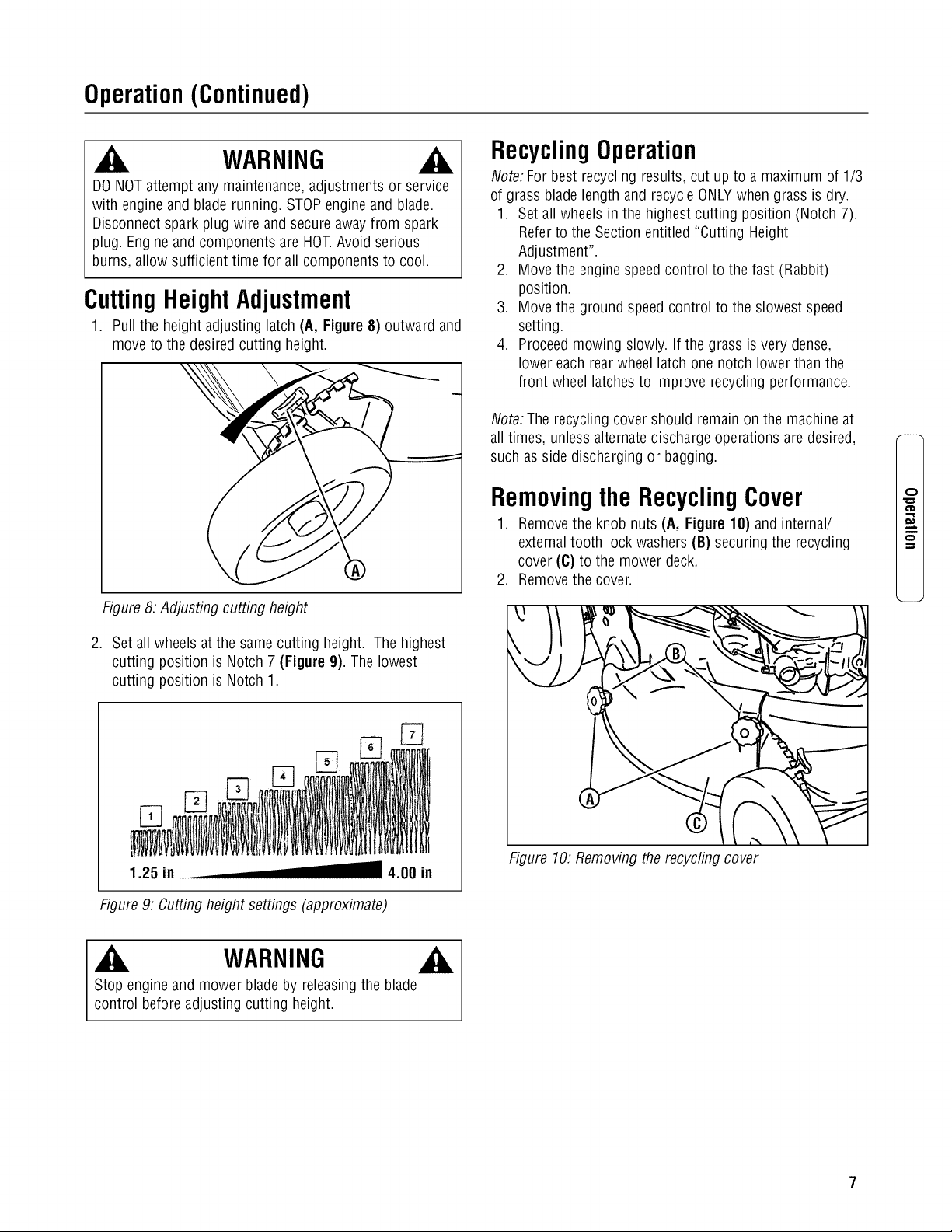
1. Pull the height adjusting latch (A, Figure8) outward and
move to the desired cutting height.
Figure 8: Adjusting cutting height
2. Set all wheels at the same cutting height. The highest
cutting position is Notch 7 (Figure 9). The lowest
cutting position is Notch 1.
1.25 in 4.00 in
Figure 9: Cutting height settings (approximate)
RecyclingOperation
Note: For best recycling results, cut up to a maximum of 1/3
of grass blade length and recycle ONLYwhen grass is dry.
1. Set all wheels in the highest cutting position (Notch 7).
Referto the Section entitled "Cutting Height
Adjustment".
2. Move the engine speed control to the fast (Rabbit)
position.
3. Move the ground speed control to the slowest speed
setting.
4. Proceed mowing slowly. If the grass is very dense,
lower each rearwheel latch one notch lower than the
front wheel latches to improve recycling performance.
Note: The recycling cover should remain on the machineat
all times, unless alternatedischarge operations are desired,
such as side discharging or bagging.
Removingthe RecyclingCover
1. Removethe knob nuts (A, Figure 10) and internal/
externaltooth lock washers (B) securing the recycling
cover (C) to the mower deck.
2. Remove the cover.
Figure 10. Removing the recycling cover
m.
WARNING
Stop engine and mower blade by releasing the blade
control before adjusting cutting height.
Operation(Continued)
t_
,m
WARNING
DONOT attempt any maintenance,adjustments or service
with engine and blade running. STOPengine and blade.
Disconnect spark plug wire and secure away from spark
plug. Engine and components are HOT.Avoid serious
burns, allow sufficient time for all components to cool.
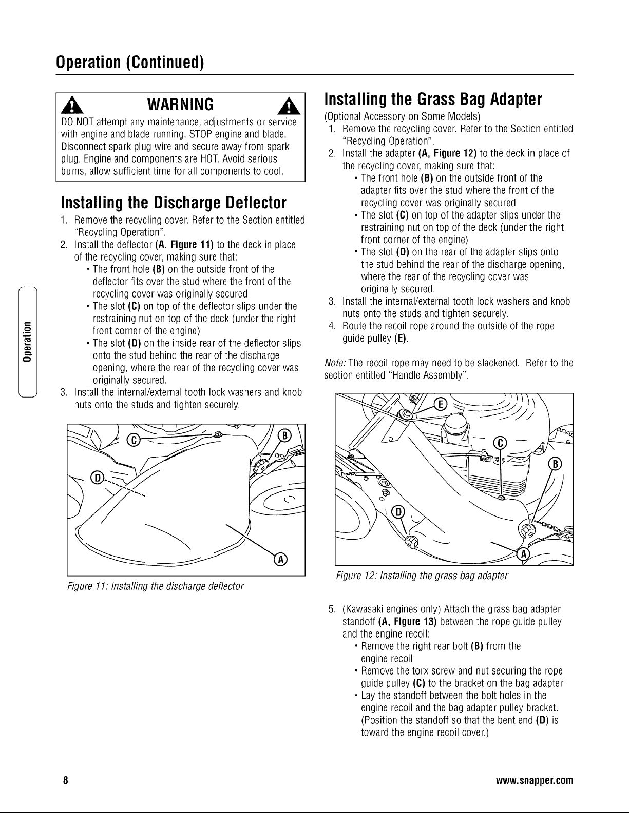
Installingthe DischargeDeflector
1. Remove the recycling cover. Refer to the Section entitled
"Recycling Operation".
2. Install the deflector (A, Figure 11) to the deck in place
of the recycling cover, making sure that:
• The front hole (B) on the outside front of the
deflector fits over the stud where the front of the
recycling cover was originally secured
• The slot (C) on top of the deflector slips underthe
restraining nut on top of the deck (under the right
front corner of the engine)
• The slot (D) on the inside rear of the deflector slips
onto the stud behind the rear of the discharge
opening, where the rear of the recycling cover was
originally secured.
3. Install the internal/externaltooth lock washers and knob
nuts onto the studs and tighten securely.
Installingthe GrassBagAdapter
(Optional Accessory on Some Models)
1. Removethe recycling cover. Refer to the Section entitled
"Recycling Operation".
2. Install the adapter (A, Figure 12) to the deck in place of
the recycling cover, making sure that:
• The front hole (B) on the outside front of the
adapter fits over the stud where the front of the
recycling cover was originally secured
• The slot (C) on top of the adapter slips under the
restraining nut on top of the deck (under the right
front corner of the engine)
• The slot (D) on the rear of the adapter slips onto
the stud behind the rear of the discharge opening,
where the rear of the recycling cover was
originally secured.
3. Install the internal/externaltooth lock washers and knob
nuts onto the studs and tighten securely.
4. Route the recoil rope around the outside of the rope
guide pulley (E).
Note: The recoil rope may needto be slackened. Referto the
section entitled "Handle Assembly".
Figure 11: Installing the discharge deflector
Figure 12. Installing the grass bag adapter
.
(Kawasaki engines only) Attach the grass bag adapter
standoff (A, Figure 13) between the rope guide pulley
and the engine recoil:
• Removethe right rear bolt (B) from the
engine recoil
• Removethe torx screw and nut securing the rope
guide pulley (C) to the bracket on the bagadapter
• Laythe standoff between the bolt holes in the
engine recoil and the bag adapter pulley bracket.
(Position the standoff so that the bent end (D) is
toward the engine recoil cover.)
8 www.snapper.com

Operation(Continued)
WARNING
DONOT attempt any maintenance,adjustments or service
with engine and blade running. STOPengine and blade.
Disconnect spark plug wire and secure away from spark
plug. Engine and components are HOT.Avoid serious
burns, allow sufficient time for all components to cool.
Installingthe GrassBagAdapter
(Continued)
• Flip the pulley over so that the bushing flange is
under the pulley. The bushing will act as a washer
betweenthe pulley and the standoff.
• Reassemblethe pulley to the bag adapter, and
install the supplied replacementbolt, fitted with the
thread sleeve, into the recoil cover. Tighten all
hardware securely.
Figure 13: Installing the adapter standoff
(Kawasakiengines only)
WARNING
DONOT operate without entire Grass Catcheror guard in
place. Grass Catcher components are subject to
deterioration during normal use. Inspect frequently and
replaceworn or damaged components immediately.
Installingthe RecyclingPlug
1. Install the recycling plug (A, Figure 14) if recycling is
desired after the bag adapter is installed. Install the
recycling plug completely and securely into the bag
adapter (B).
IMPORTANT.Install the grass bag as a safeguard.
2. Refer to the Section entitled "Recycling Operation".
Figure 14. Installing the recycfing plug
Installingthe GrassBag
(Door Type Bag)
1. Install the grass bag adapter.Refer to the Section
entitled "Installing the Grass BagAdapter".
2. Install the grass bag by sliding the connector (A, Figure
15) over the adapter flange.
3. Attach the grass bag hooks (B) over the middle handle
cross bar.
®
Figure 15. Installing the grass bag
WARNING
GrassCatcher bags used on SNAPPERproducts are made
of woven fabric, and are subject to deterioration and wear
during normal usage. Check condition of bag before each
use. Immediately replace worn or damaged catcher bags
with only bags recommended by SNAPPER. The grass
catcher is optional equipment on some models.
m.
Maintenance
p,,
q-.
.m
_E
Maintenance-Introduction
To retain the quality of the mower, use genuine SNAPPER
replacement parts only. Contact a local SNAPPERdealer for
parts and service assistance.For the correct part or
information for a particular mower, always mention the
model and serial number.
WARNING
DONOT attempt any maintenance,adjustments or service
with engine and blade running. STOPengine and blade.
Disconnect spark plug wire and secure away from spark
plug. Engine and components are HOT.Avoid serious
burns, allow sufficient time for all components to cool.
Wear heavy leather gloves when handling or working
around cutting blades. Bladesare extremely sharp and can
causesevere injury.
Service- After First5 Hours
Change Engine Oil
1. Refer to the EngineManual for proper oil specifications,
procedures and proper service intervals.
2. For the simplest/cleanest oil change, simply turn the
mower on its side to drain the oil, as shown. Drain the
oil through the dipstick tube (A, Figure 16) into a
container. Allow sufficient time for all the oil to drain.
Important: Drain the fuel tank before tipping the machine.
DO NOT tip the machinewith the carburetor or spark plug
down. Oil from the crankcasewill saturate the air filter and
causethe engine to be hard to start or not start at all. If
contamination does occur, the air filter will haveto be
replaced.
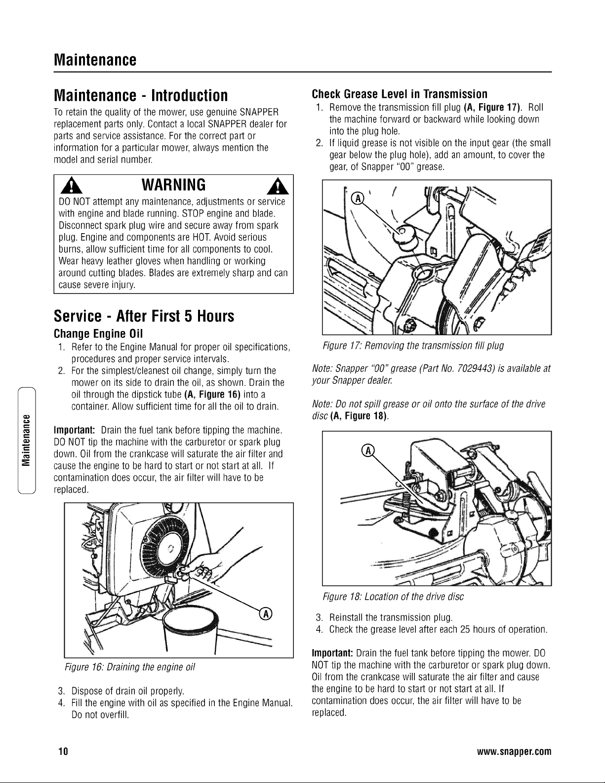
CheckGreaseLevel in Transmission
1. Removethe transmission fill plug (A, Figure 17). Roll
the machine forward or backward while looking down
into the plug hole.
2. If liquid grease is not visible on the input gear (the small
gear below the plug hole), add an amount, to cover the
gear, of Snapper "00" grease.
Figure 17. Removing the transmission fill plug
Note: Snapper "00" grease (Part No. 7029443) is available at
your Snapper dealer.
Note: Do not spill grease or oil onto the surface of the drive
disc (A, Figure 18).
%
Figure 16: Draining the engine oil
3. Dispose of drain oil properly.
4. Fill the enginewith oil as specified in the Engine Manual.
Do not overfill.
Figure 18: Location of the drive disc
3. Reinstall the transmission plug.
4. Checkthe grease level after each 25 hours of operation.
Important:Drain the fuel tank before tipping the mower. DO
NOTtip the machine with the carburetor or spark plug down.
Oil from the crankcase will saturate the air filter and cause
the engine to be hard to start or not start at all. If
contamination does occur, the air filter will haveto be
replaced.
10 www.snapper.com

Maintenance(Continued)
WARNING
DONOT attempt any maintenance,adjustments or service
with engine and blade running. STOPengine and blade.
Disconnect spark plug wire and secure away from spark
plug. Engine and components are HOT.Avoid serious
burns, allow sufficient time for all components to cool.
Wear heavy leather gloves when handling or working
around cutting blades. Bladesare extremely sharp and can
causesevere injury.
Check Mower Blade
1. Disconnect the spark plug wire and securethe end away
from the plug.
2. Tilt the mower up on its rearwheels for accessto the
blade cap screw (A, Figure19). Do not tilt the mower
with the spark plug or carburetor down.
Important:Drain the fuel tank before tipping the mower. DO
NOTtip the machine with the carburetor or spark plug down.
Oil from the crankcasewill saturate the air filter and cause
the engineto be hard to start or not start at all. If
contamination does occur, the air filter will haveto be
replaced.
3. Checkthe torque of the bladecap screw. Recommended
torque should be 40 ft. Ibs.
4. Checkthe bladefor sharpness, wear and damage. Refer
to the Section entitled "BladeWear Limits".
Figure 19. Tightening the blade cap screw
Check Engine Drive Belt
1. Visually check the engine drive belt for cracking, fraying,
severedor exposed belt strands. If worn or damaged,
replace the belt before operating the mower.
Check Transmission Poly-V Belt
1. Visually check the poly-v belt for cracking, fraying, sev-
ered or exposed belt strands. If worn or damaged,
replacethe belt before operating the mower.
Service- Periodic
Perform all maintenanceas described in the "Service
Schedule" section of this manual.
Engine
Service the engine according to the engine owner's manual.
Air Filter
Referto the engine owner's manual for service instructions.
EngineOil
Referto the engine owner's manual for service instructions.
StorageProcedure
Referto the Engine Owner's Manual for directions regarding
engine storage preparations. Preparethe mower for "end of
season" storage as follows:
1. Drain the fuel from the fuel tank and let the engine run
until all fuel is out of the carburetor.
2. Disconnect and remove the spark plug wire awayfrom
the spark plug before any other preparations are made!
3. Tapeall openings closed to preventspraying water into
the exhaust or air intakes during washing.
4. Tilt the mower up on its rear wheels and thoroughly
clean the underside of the deck. Do not tilt the mower
with the spark plug or carburetor down. Scrapeaway
any accumulation of grass with a putty knife and/or
wire brush.
5. Lubricate all exposed metal with a light coating of oil to
prevent corrosion.
6. On self-propelled models, disconnect the transfer rod
clip and remove the ground speed control rod before
folding the handles.
7. Loosen the handle knobs. Carefully fold the handles
forward, "flexing" the control cables to prevent cable
damage.
8. Store the mower in a shed or other dry area, protected
from weather.
m.
€'D
11
Maintenance(Continued)
,m
_E
WARNING
DONOT attempt any maintenance,adjustments or service
with engine and blade running. STOPengine and blade.
Disconnect spark plug wire and secure away from spark
plug. Engine and components are HOT.Avoid serious
burns, allow sufficient time for all components to cool.
Wear heavy leather gloves when handling or working
around cutting blades. Bladesare extremely sharp and can
causesevere injury.
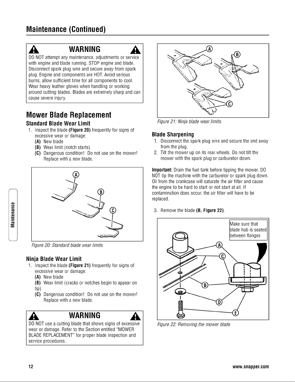
MowerBladeReplacement
Standard Blade Wear Limit
1. Inspect the blade(Figure 20) frequently for signs of
excessivewear or damage:
(A) New blade
(B) Wear limit (notch starts)
(C) Dangerous condition! Do not use on the mower!
Replacewith a new blade.
Figure 20: Standard blade wear limits
Ninja Blade Wear Limit
1. Inspect the blade(Figure 21) frequently for signs of
excessivewear or damage:
(A) New blade
(B) Wear limit (cracks or notches begin to appearon
tip)
(C) Dangerous condition! Do not use on the mower!
Replacewith a new blade.
WARNING
DONOT use a cutting bladethat shows signs of excessive
wear or damage.Refer to the Section entitled "MOWER
BLADEREPLACEMENT"for proper blade inspection and
service procedures.
Figure 21: Ninja blade wear fimits
BladeSharpening
1. Disconnect the spark plug wire and secure the end away
from the plug.
2. Tilt the mower up on its rear wheels. Do not tilt the
mower with the spark plug or carburetor down.
Important:Drain the fuel tank before tipping the mower. DO
NOTtip the machine with the carburetor or spark plug down.
Oil from the crankcase will saturate the air filter and cause
the engineto be hard to start or not start at all. If
contamination does occur, the air filter will haveto be
replaced.
3. Remove the blade (B, Figure22).
Makesure that
bladehub is seatedI
[betweenfanges J
i
Figure 22: Removing the mower blade
12 www.snapper.com
Maintenance(Continued)
WARNING
DO NOTattempt any maintenance, adjustments or service
with engine and blade running. STOPengineand blade.
Disconnect spark plug wire and secure awayfrom spark
plug. Engineand components are HOT.Avoid serious
burns, allow sufficient time for all components to cool.
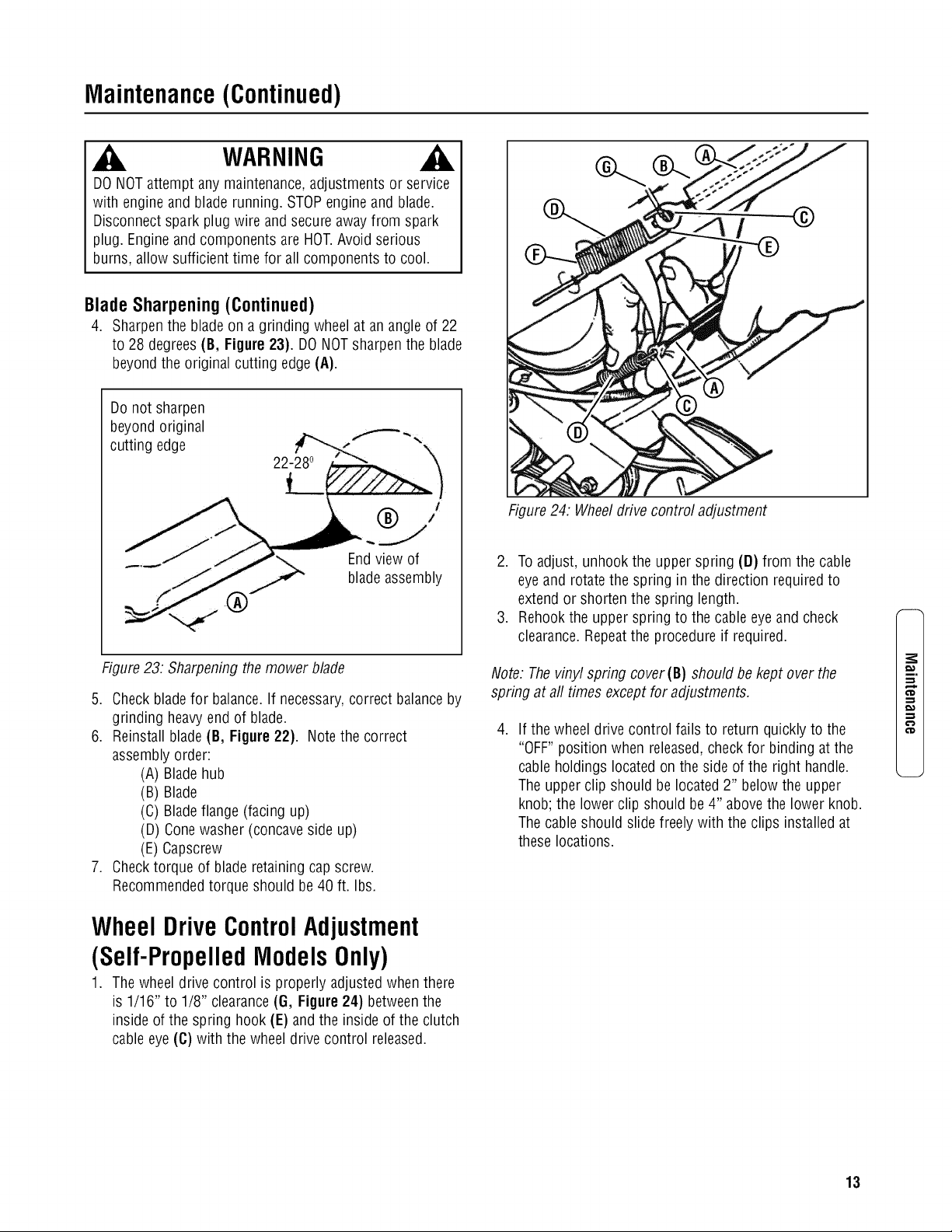
BladeSharpening(Continued)
4. Sharpen the bladeon a grinding wheel at an angle of 22
to 28 degrees (B, Figure 23). DO NOTsharpen the blade
beyond the original cutting edge(A).
Do not sharpen
beyond original
cutting edge
Endview of
bladeassembly
Figure 23: Sharpening the mower blade
5. Check blade for balance.If necessary,correct balance by
grinding heavyend of blade.
6. Reinstall blade (B, Figure 22}. Note the correct
assembly order:
(A) Blade hub
(B) Blade
(C) Bladeflange (facing up)
(D) Conewasher (concave side up)
(E) Capscrew
7. Checktorque of blade retaining cap screw.
Recommendedtorque should be 40 ft. Ibs.
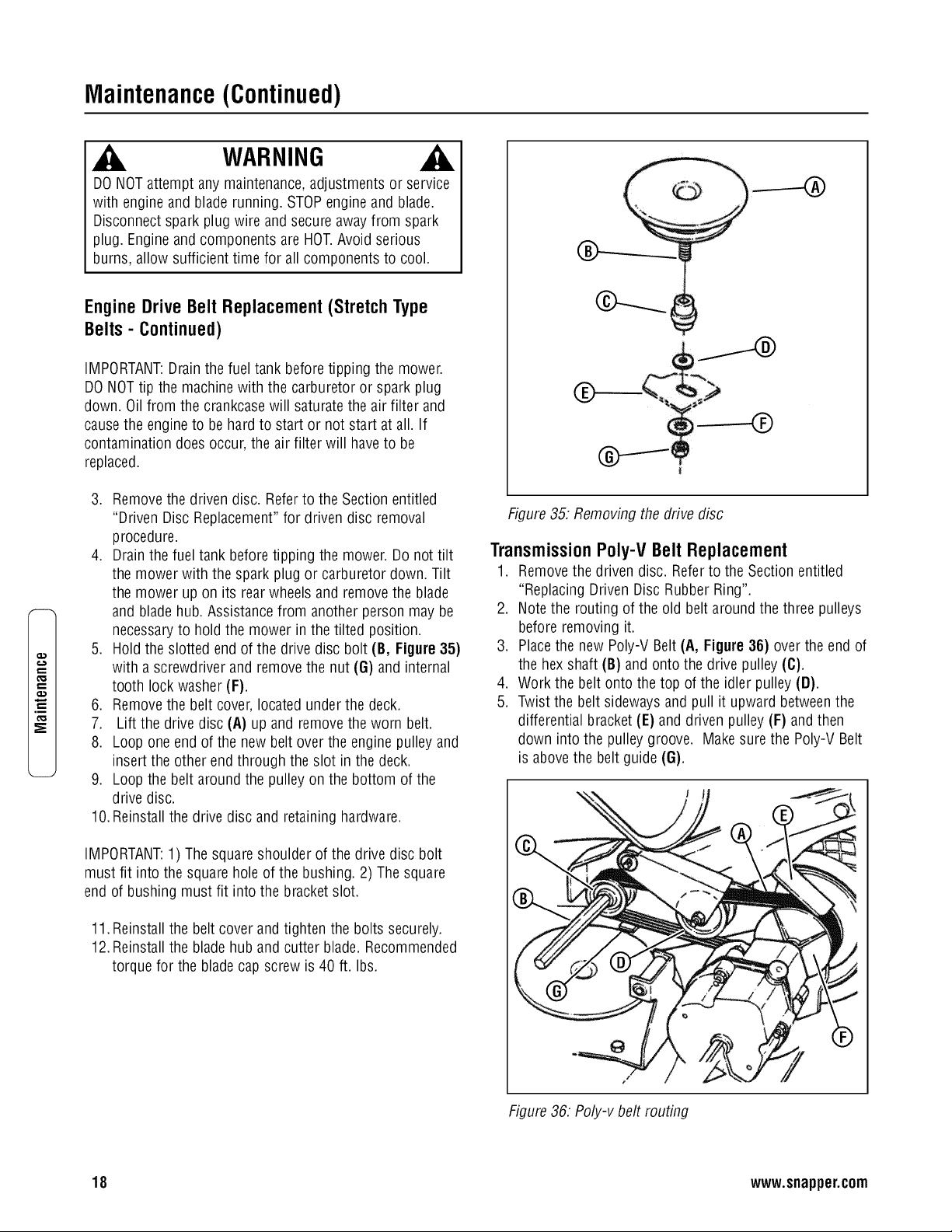
Wheel DriveControlAdjustment
(Self-PropelledModelsOnly)
1. The wheel drive control is properly adjusted when there
is 1/16" to 1/8" clearance (G, Figure24) betweenthe
inside of the spring hook (E) and the inside of the clutch
cable eye (C) with the wheel drive control released.
Figure 24: Wheeldrive control adjustment
2. To adjust, unhook the upper spring (D) from the cable
eye and rotate the spring in the direction required to
extend or shorten the spring length.
3. Rehook the upper spring to the cable eye and check
clearance. Repeatthe procedure if required.
Note. Thevinyl spring cover(B) should be kept over the
spring at aft times except for adjustments.
.
If the wheel drive control fails to return quickly to the
"OFF" position when released,check for binding at the
cable holdings located on the side of the right handle.
The upper clip should be located 2" below the upper
knob; the lower clip should be 4" above the lower knob.
The cable should slide freely with the clips installed at
these locations.
m.
€'D
13

Maintenance(Continued)
e,,,
t_
.m
_E
WARNING
DO NOTattempt any maintenance, adjustments or service
with engine and blade running. STOPengineand blade.
Disconnect spark plug wire and secure awayfrom spark
plug. Engineand components are HOT.Avoid serious
burns, allow sufficient time for all components to cool.
Drivenand DriveDiscService
If the mower does not propel itself properly, check for the
following problems:
Figure 25. Wheel drive components
1. Greaseon the drive disc (A, Figure 25) causing
slippage.
2. Broken or disconnected drive spring (B).
3. Driven disc (C) is out of adjustment.
4. Driven disc rubber is worn - does not contact drive disc
properly.
5. Worn Poly-V belt (D) or engine drive belt (E).
If any of the above (1 thru 5) are causing problems, service
as follows:
Cleaning Drive Disc & Driven Disc
If oil or greaseon the drive disc or driven disc is causing
slippage, clean the discs as follows:
1. Wipe away any oil or grease with a clean cloth.
2. Use either an approved grease solvent or hot, soapy
water to clean drive disc or driven disc.
3. Rinse components with clean water.
4. Dry components with a clean cloth.
DriveSpringRepair/Replacement
If the drive spring (A, Figure 26) is loose, reconnect. If the
spring is broken, replacewith a new spring.
Note: Usea pair of needlenose pliers to install the drive
spring.
IMPORTANT:If the drive system continues slipping, refer to
the Troubleshooting section.
Figure 26: Replacingthe drive spring
Driven Disc Adjustment
If the drive disc and driven disc are clean and the mower
drive is still slipping, adjust the driven disc as follows:
1. Move the ground speed control (A, Figure 27) into the
'fast' position.
Figure 27: Theground speed control
14 www.snapper.com

Maintenance(Continued)
WARNING
DO NOTattempt any maintenance, adjustments or service
with engine and blade running. STOPengineand blade.
Disconnect spark plug wire and secure awayfrom spark
plug. Engineand components are HOT.Avoid serious
burns, allow sufficient time for all components to cool.
Driven Disc Adjustment (Continued)
2. Remove the driven disc spring (A, Figure 28) from the
driven disc assembly (B). Also remove the pin and
washer (C) from the transfer rod (D), and removethe
end of the transfer rod from the hole in the driven disc
assembly.
Figure 28: Adjusting the driven disc
3. Slide the driven disc assembly over to 1/8" (A, Figure
29) from the outside edge of the drive disc (B).
4. Loosen the jam nut (A, Figure 38) securing the transfer
rod (B) to the ball joint (C) on the pivot bracket (D).
5. Turn the rod in or out of the ball joint until the end of the
rod aligns with the hole (E) in the driven disc assembly
from which the rod was removed.
IMPORTANT:Do not move the pivot bracket.
6. Reinstall the rod as removed in Step 2. Move the ground
speed control to the 'slow' position, then back to the
'fast' position. Recheckthe 1/8" measurement described
previously. Readjustas needed.Tighten the nut when
finished.
7. Reinstall the driven disc spring to the driven disc
assembly.
Figure 29: Proper driven disc adjustment
Figure 30: Adjusting the transfer rod
Driven Disc Replacement
If the rubber on the driven disc is badly chunked or worn, it
must be replaced. Install a new driven disc as follows:
1. Removethe pin and washer (C, Figure 28) from the
transfer rod (D), and remove the end of the transfer rod
from the hole in the driven disc assembly.
m.
15

Maintenance(Continued)
e,,,
t_
.m
_E
WARNING
DO NOTattempt any maintenance, adjustments or service
with engine and blade running. STOPengineand blade.
Disconnect spark plug wire and secure awayfrom spark
plug. Engineand components are HOT.Avoid serious
burns, allow sufficient time for all components to cool.
Driven Disc Replacement (Continued)
2. Using needle nose pliers, unhook the drive spring (A,
Figure 31) and slide the driven disc assembly off the
hex shaft.
3. Remove the two snap rings (A, Figure 32) which secure
the rubber driven disc (B) to the driven disc assembly.
4. Install a new rubber driven disc onto the driven disc
assembly, and secure with the retaining rings.
5. Reversethe above proceduresfor reassembly and
installation of the driven disc assembly.
Driven Disc Bearing Replacement
IMPORTANT:The bearing on these machines is staked into
the thrust plate. The bearing will haveto be driven out with a
mallet and a large punch. A new bearing with four retaining
screws will haveto be purchased to replace existing bearing.
If the driven disc bearing requires replacement, replace the
bearing as follows:
1. Removethe driven disc assembly. Refer to the Section
entitled "Driven Disc Replacement".
2. Remove both snap rings (A, Figure 32) that secure the
rubber driven disc (B) to the thrust plate.
3. Slide the rubber driven disc hub out of the bearing.
4. Drive out the existing bearing (C).
5. Install a new bearing and secure to the thrust plate with
four retaining screws. Tighten the screws securely.
6. Reassemblethe components in reverse order.
NOTE:Be sure to replace the shim washer (D) when
reassembfingthe driven disc assembly.
Figure 31. Removing the driven disc assembly
Figure 32: Replacing the driven disc
16 www.snapper.com

Maintenance(Continued)
WARNING
DO NOTattempt any maintenance, adjustments or service
with engine and blade running. STOPengineand blade.
Disconnect spark plug wire and secure awayfrom spark
plug. Engineand components are HOT.Avoid serious
burns, allow sufficient time for all components to cool.
Replacing the Bearing On the Pulley End Of the
Hex Shaft
To replace the bearing on the pulley end of the hex shaft,
proceed as follows:
1. Hold the hex shaft with an adjustable wrench held next
to the pulley.
2. Remove the 3/8" hex lock nut (B, Figure33), located on
the outside of the right wheel bracket.
3. Remove the holder (A), O-ring (C) and bearing (D).
4. Install the new bearing.
5. Carefully install the new O-ring over the outside of the
new bearing.
6. Install the bearing holder, and secure with screws.
7. Install the 3/8" hex lock nut.
BeltService
On self-propelled mowers, the engine belt (A, Figure 34)
transmits power from the engine pulley (B) to the drive disc
(C). The drive disc powers the poly-v belt, which engages the
transmission that powers the rearwheels. Should these belts
become worn, they could cause slippage,which would
impair mower performance. The condition of the engine belt
and poly-v belt should be checked after every 25 hours of
mower operation.
Engine Drive Belt Replacement (Stretch Type
Belts)
1. Empty the fuel tank.
2. Note the belt routing (Figure 34). There is no idler
pulley on these models to disconnect.
f ,.. o "_ \//>_ "l,
\% \/ /I//
Figure 34. Engine drive belt routing
i.
€'D
€'D
Figure 33. Replacingthe hex shaft bearing
17
Maintenance(Continued)
e,,,
t_
.m
_E
WARNING
DO NOTattempt any maintenance, adjustments or service
with engine and blade running. STOPengineand blade.
Disconnect spark plug wire and secure awayfrom spark
plug. Engineand components are HOT.Avoid serious
burns, allow sufficient time for all components to cool.
EngineDrive Belt Replacement(StretchType
Belts- Continued)
IMPORTANT:Drain the fuel tank before tipping the mower.
DO NOT tip the machinewith the carburetor or spark plug
down. Oil from the crankcase will saturate the air filter and
causethe engine to be hard to start or not start at all. If
contamination does occur, the air filter will haveto be
replaced.
3. Remove the driven disc. Referto the Section entitled
"Driven Disc Replacement"for driven disc removal
procedure.
4. Drain the fuel tank before tipping the mower. Do not tilt
the mower with the spark plug or carburetor down. Tilt
the mower up on its rear wheels and removethe blade
and bladehub. Assistance from another person may be
necessaryto hold the mower in the tilted position.
5. Hold the slotted end of the drive disc bolt (B, Figure 35)
with a screwdriver and remove the nut (G) and internal
tooth lock washer (F).
6. Remove the belt cover, located under the deck.
7. Lift the drive disc (A) up and remove the worn belt.
8. Loop one end of the new belt over the engine pulley and
insert the other end through the slot in the deck.
9. Loop the belt around the pulley on the bottom of the
drive disc.
10.Reinstall the drive disc and retaining hardware.
IMPORTANT:1) The square shoulder of the drive disc bolt
must fit into the square hole of the bushing. 2) The square
end of bushing must fit into the bracket slot.
11.Reinstall the belt cover and tighten the bolts securely.
12.Reinstall the blade hub and cutter blade. Recommended
torque for the blade cap screw is 40 ft. Ibs.
------4b
)
Figure 35. Removing the drive disc
Transmission Poly-V Belt Replacement
1. Remove the driven disc. Referto the Section entitled
"Replacing Driven Disc Rubber Ring".
2. Note the routing of the old belt around the three pulleys
before removing it.
3. Place the new Poly-V Belt (A, Figure 36) over the end of
the hex shaft (B) and onto the drive pulley (C).
4. Work the belt onto the top of the idler pulley (D).
5. Twist the belt sideways and pull it upward betweenthe
differential bracket (E) and driven pulley (F) and then
down into the pulley groove. Make sure the Poly-V Belt
is above the belt guide (G).
J
Figure 36. Poly-v belt routing
18 www.snapper.com

Maintenance(Continued)
BatteryService
New BatteryPreparation
1. Remove the battery from the carton.
2. Placethe battery in a well ventilated area on a level non-
concrete surface.
3. Remove the battery cell caps. Fill the cells as required
with electrolyte (supplied with battery) to the proper
level. Filling the battery with electrolyte will bring the
battery to 80% charged state.
4. With the cell caps removed, connect the battery charger
to the battery terminals; REDto positive (+) and BLACK
to negative (-) terminal.
IMPORTANT:Neverplace anything in the battery other than
the specified electrolyte.
5. Slow charge the battery at 1 amp for 2 hours to bring
the battery to full charge.
6. After charging, check the level of electrolyte and add as
neededto bring to the proper fluid level.
7. Reinstall the cell caps.
8. Install the battery into the power unit.
9. Connect the positive (+) cable (red) first, from the wiring
harness to the positive terminal (+) on the battery using
the bolt and nut provided in the hardware bag. Connect
the negative (-) cable (black) last, to the negativetermi-
nal (-) on the battery using the bolt and nut. Apply a
small amount of grease over the terminals to prevent
corrosion.
WARNING
DONOToverfill batterywithelectrolyte.Shieldthe positive
terminalwithterminalcoverlocatedonbatteryharness.This
preventsmetalfrom touchingthe positiveterminal,which could
causesparks.Theelectrolyte(acid)producesa highlyexplosive
gas.Keepall sparks,flameandfire awayfrom areawhen
chargingbatteryor whenhandlingelectrolyteor battery.
Electrolyte(acid)is a highlycorrosiveliquid.Weareyeprotection.
Washaffectedareasimmediatelyafterhavingeyeor skincontact
with electrolyte(acid).Batteryacid is corrosive.Rinseemptyacid
containerswithwaterandmutilatebeforediscarding.If acidis
spilledon battery,bench,or clothing,etc.,Flushwith clearwater
andneutralizewith bakingsoda.Neverattemptto chargebattery
while installedonthe walk behind.Neveruse"BOOST"chargers
onthe battery.
BatteryService
1. Removethe battery.
2. Place the battery in a well ventilated areaon a level sur-
face.
3. Using distilled water, refill the cells as required to cover
the cell plates.
4. With the cell caps removed, connect the battery charger
to the battery terminals. Redto positive (+) terminal
and black to negative (-) terminal.
5. Slow charge the battery at 1 amp for 10 hours.
6. If the battery will not accept a charge or is partially
charged after 10 hours of charging at 1 amp, replace
with a new battery.
BatteryStorage
If the Walk Behindis to be stored out of season on its rear
bumper, it is recommendedthe battery be removed, charged
and stored.
1. Removethe battery.
2. Perform battery service.
3. Bring the battery to full charge, if required.
4. Store the battery in an area awayfrom the Walk Behind
on a wood surface. DO NOT STOREBATTERYON A
CONCRETESURFACE.
Battery Testing
There are two types of battery tests: Unloaded and Loaded.
The unloaded test is the procedure that will be discussed. It's
the simplest and most commonly used. An unloadedtest is
made on a battery without discharging current. To perform
unloaded testing, check charge condition using either a
hydrometer or voltmeter.
.
.
Using a voltmeter, voltage readings appear instantly to
show the state of charge. Rememberto hook the posi-
tive leadto the battery's positive terminal, and the nega-
tive leadto the negative terminal.
A hydrometer measuresthe specific gravity of each cell.
The specific gravity tells the degree of charge; generally,
a specific gravity of about 1.265 to 1.280 indicates full
charge. A readingof 1.230 to 1.260 indicates the battery
should be charged. The chart below shows the charge
level as measured by syringe float hydrometer, digital
voltmeter and five ball hydrometer.
Methodsof CheckingBattery Condition
State of Charge SyringeHydrometer Digital Voltmeter Five Ball Hydrometer
100% Chargedw/Sulfate Stop 1.280 12.80v FiveBalls Floating
100% Charged 1.265 12.60v Four Balls Floating
75% Charged 1.210 12.40v Three Balls Floating
50% Charged 1.160 12.10v Two Balls Floating
25% Charged 1.120 11.90v One Ball Floating
0% Charged Lessthan 1.100 Lessthan 11.80v Zero Balls Floating
m,
¢D
€'D
19

,m
ServiceSchedule
ITEM
Engine Oil
Air Pre-Cleaner
Air Cleaner
Spark Plug
EngineCooling
System
Drive Belts
Mower Blade
Mower Deck
Transmission
Grease
Drive Disc
SERVICE
PERFORMED
Check Oil Level
Initial Oil Change
Periodic Oil Change
CleanSponge Element
Cleanor Replace
Replace
CleanShroud & Fins
Check tor Wear and
Tension
Check for wear, Damage
& Replacement
Clean Debris
Accumulation
CheckGrease Level
Periodic GreaseCheck
Check for Wear Damage
and Replacement
REF.
Page5
Page10
Page11
EngineManual
EngineManual
EngineManual
EngineManual
EACH
USE
5
HRS
X
Page11, 17
Page12 X
Page5 X
Page10
Page10
Page13-16
* Changeoil every 25 hours when operating under heavy load or high temperatures.
** Cleanmore often under dusty conditions or when air debris is present.
25
HRS
X_
X**
X**
5O
HRS
lOO
HRS
X
X**
Maintenance/ReplacementParts
EngineSpeed Control (Briggs Engines)
EngineSpeed Control (KawasakiEngines)
BladeControl Cable (Briggs Engines)
BladeControl Cable (KawasakiEngines)
Clutch Pull Cable
Cutter Blade(Air Lift Compatible)
Cutter Blade(Mulching)
Cutter Blade(Not Air Lift Compatible)
Cutter Blade(Ninja - Quad Edge)
Wheel Drive Pulley to Transmission Pulley Belt
Engineto Drive Disc Belt
Cantilever Drive Tire Assembly
Rubber Drive Tire
Parts Manual for 21" Steel Deck Walk Behind Mower Series 19 - Recycling ('R') Series
Parts Manual for 21" Steel Deck Walk Behind Mower Series 19
EACH
SEASON
X
X
X
7074460
7074138
7034608
7074141
7034604
7019795
7017168
7026691
7026407
7012354
7046784
7073528
7041855
7006149
7006150
20 www.snapper.com

Troubleshooting
PROBLEM
Engine Will Not Start Using
Recoil Starter
Engine Will Not Start (Electri(
Start Models)
Engine Stalls or Stops After
Running
Engine Loses Power
Excessive Vibration
IVlowerWill Not IVloveLoss
Of Traction (Self-Propelled
Models)
Cutting Grass Improperly
Poor Grass Discharge
Oil Leaking
PROBABLECAUSE
1. Fuel tank empty. 1.
2. Engine needs choking or priming. 2.
3. Spark plug wire disconnected. 3.
4. Kawasaki Engines Only - Fuel shut-oft in the 'Off' 4.
)osition.
1. Fuel tank empty. 1.
2. Engine needs choking or priming. 2.
3. Spark plug wire disconnected. 3.
4. Wiring harness disconnected. 4.
5. Battery dead. 5.
6. Kawasaki Engines Only - Fuel shut-off in the 'Off' 6.
)osition.
1. Blade control is released or is not being held
securely against handle.
2. Fuel tank empty.
3. Engine air pre-cleaner and or air cleanerdirty.
4. Spark plug detective or gap set improperly.
CORRECTIVEACTION
Fill tuel tank with tresh fuel.
Choke/Prime. Check Engine IVlanualfor Instructions.
Place spark plug wire onto spark plug.
lurn Fuel shut-oft to 'On' position.
Fill tuel tank with tresh tuel.
Choke/Prime. Check Engine Manual for Instructions.
Place spark plug wire onto spark plug.
Connect wiring harness.
Charge or replace battery.
lurn Fuel shut-off to 'On' position.
1. Blade control should be held securely against handle
at all times during operation of mower.
2. Fill with fuel to proper level.
3. Clean tree of all debris.
4. Service spark plug.
5. Water, debris or stale fuel in fuel system. 5.
6. Kawasaki Engines Only - Fuel shut-oft in the 'Ott' 6.
)osition.
1. Engine air pre-cleaner or air cleaner dirty. 1.
2. Spark plug faulty. 2.
3. Water, debris or stale fuel in fuel system. 3.
1. Damaged, out of balance or bent mower blade. 1.
2. Loose blade components. 2.
3. Loose or missing air Iitt (it equipped). 3.
4. Lumpy or trayed belt. 4.
1. Build-up of debris on or around wheel drive 1.
components.
2. Driven disc slipping.
3. Drive belt requires replacement.
4. Damaged transmission.
1. Cutting height too low or high.
2. Engine speed too slow.
3. Forward ground speed too fast.
4. lerraced cut, side to side.
5. Excessive deck pitch, front to rear.
6. Cutting blade dull or damaged.
1. Engine speed too fast. 1.
2. Forward speed too tast. 2.
3. Grass is wet. 3.
4. Excessively worn or damaged blade. 4.
5. Build up of grass clippings and debris under deck. 5.
6. Improper blade installed on deck. 6.
7. Blade installed improperly on deck. 7.
1. Leaking engine case. 1.
2.
Drain and clean fuel system.
lurn Fuel shut-oft to 'On' position.
Clean or replace tilters.
Service spark plug.
Drain and clean fuel system.
Service mower blade.
Service and tighten loose parts.
Replaceair lifts, lighten to proper torque.
Replace belt.
Clean debris.
2. Clean or replace driven disc.
3. Replace drive belt.
4. Contact authorized SNAPPERdealer.
1. Adjust cutting height.
2. Move engine speed control to 'Fast' position.
3. Move ground speed control to a slower speed.
4. Adjust height of cut with height adjust levers.
5. Adjust height of cut with height adjust levers.
6. Sharpen cutting edges or replace blade.
Move engine speed control to 'Fast' position.
IVloveground speed control to a slower speed.
IVlowwhen grass is dry.
Service mower blade.
Clean deck.
Install proper SNAPPEHblade.
Install blade properly.
Contact authorized SNAPPERdealer.
Check and tighten drain plug.
3. IVlakesure dip stick or oil tiller cap is securely in
)lace.
=3"
m.
21

t_
,m
2 YEAR LIMITED WARRANTY
For two (2) years from purchase date for the original purchaser's residential, non-commercial use, SNAPPER,through any
authorizedSNAPPERdealerwill replace,free of charge (except for taxes where applicable), any part or parts found upon
_xamination by the factory at McDonough, Georgia,to be defective in material or workmanship or both.
For ninety (90) days from purchasedate for the original purchaser's commercial, rental, or other non-residential use, SNAP-
PER,through any authorized SNAPPERdealer will replace,free of charge,any part or parts found upon examination by the
[actory at McDonough, Georgia,to be defective in material or workmanship or both.
&ll transportation costs incurred by the purchaser in submitting material to an authorized SNAPPERdealerfor replacement
underthis warranty must be paid by the purchaser.
This warranty does not apply to certain transmissions, to engines and their components, and batteries, as these items arewar-
ranted separately. This warranty does not apply to parts that havebeen damaged by accident, alteration, abuse, improper
lubrication, normal wear, or other causebeyond the control of SNAPPER.This warranty does not cover any machine or com-
ponent part that has been altered or modified changing safety, performance, or durability.
Batteries have a one (1) year warranty period with free replacement if required for one (1) year from the original purchase
date.SNAPPERwill not be responsible for any installation cost incurred. The battery warranty only covers original equipment
batteries and does not cover damageto the battery or machine caused by neglect or abuse, destruction by fire, explosion,
[reezing, overcharging, improper maintenance, or use of improper electrolyte.
There is no other express warranty.
DISCLAIMMEROFWARRANTY
Implied warranties, includingthoseof merchantabilityand fitness for a particular purpose, are limited to two (2) years
[rom purchasedate for the original purchaser'sresidential or other non-commercialuse, and ninety(90) daysfrom pur-
chase for the original purchaser'scommercial, rental or other non-residentialuse, and to the extent permittedby law, any
andall implied warranties are excluded. This is the exclusiveremedy. Liabilities for consequentialdamages, underany
andall warrantiesare excluded.
Somestates do not allow limitations on how long an implied warranty lasts, or do notallow the exclusionor limitation of
incidentalor consequentialdamages, so the abovelimitation or exclusionmay notapply to you.
Thiswarranty gives you specific legal rights, and you may also have other rights which vary from state to state.
WARNING:THE USEOF REPLACEMENTPARTSOTHERTHAN GENUINESNAPPERPARTSMAY IMPAIR THESAFETYOF
SNAPPERPRODUCTSAND WILL VOIDANY LIABILITYANDWARRANTYBYSNAPPERASSOCIATEDWITH THE USEOF
SUCHPARTS.
IMPORTANT:
Pleasefill out the attached SNAPPERProduct Registration Card immediately and mail to:
Snapper'sProductRegistrationCenter, P.O.Box1379, IVlcDonough,Georgia30253
22 www.snapper.com
04
4- SLOPE GUIDE
........ :..../.b" DE_D_... SIGHT AND HOLD THIS GUIDE LEVEL WITH A VERTICAL TREE,
I ".... -'..'.._S A CORNER OF A STRUCTURE, A POWER LINE POLE, OR A FENCE.
j ........................
...... .....................
!
I
I
Operate a walk-behind mower
across the face of slopes,
never up or down slopes.
10 DEGREES 15 DEGREES
Operate a riding mower
up or down slopes, never
across the face of slopes.
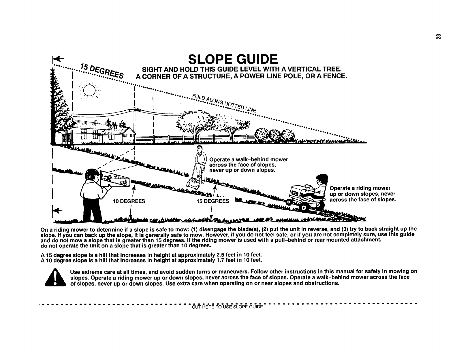
On a riding mower to determine if a slope is safe to mow: (1) disengage the blade(s), (2) put the unit in reverse, and (3) try to back straight up the
slope. If you can back up the slope, it is generally safe to mow. However, if you do not feel safe, or if you are not completely sure, use this guide
anddo not mow a slope that is greater than 15 degrees. If the riding mower is used with a pull-behind or rear mounted attachment,
do not operate the und on a slope that is greater than 10 degrees.
A 15 degree slope is a hill that increases in height at approximately 2.5 feet in 10 feet.
A 10 degree slope is a hill that increases in height at approximately 1.7 feet in 10 feet.
Use extreme care at all times, and avoid sudden turns or maneuvers. Follow other instructions in this manual for safety in mowing on
slopes. Operate a riding mower up or down slopes, never across the face of slopes. Operate a walk-behind mower across the face
of slopes, never up or down slopes. Use extra care when operating on or near slopes and obstructions.
................................. _U'T_E'R_fO'U§E'_GP__&_D'E.................................

Notes
24 www.snapper.com

Notes
25

21" STEELDECK
WALKMOWERS
SERIES19
Product Specifications
Deck Size
Height of Cut
Transmission Type (Self-Propelled Models)
Ground Speed (Self-Propelled Models)
Engine Power - Briggs Quantum / DOV
Engine Power- Briggs Intek
Engine Power- Kawasaki
Engine Displacement - Briggs DOV
Engine Displacement - Briggs Quantum / Intek
Engine Displacement - Kawasaki
Fuel Tank Capacity - Briggs (all)
Fuel Tank Capacity - Kawasaki
21 in
1,25- 4 in
Gear
1 -4 mph
6.50ft-lbs (gross)
8.75ft-lbs (gross)
6.0 hp (gross)
160cc
190cc
180cc
1.6 qt
2,1 qt
CommonServiceParts
Cutter Blade(Ninja - Quad)
Drive Belt (Engine)
Drive Belt (Transmission)
Parts Manual (Recycling)
Parts Manual
Part Number
7026407
7046784
7012354
7006149
7006150
EnginePower RatingInformation:The gross power rating for individual gas engine models is labeled in accordancewith
SAE(Society of Automotive Engineers) code J1940 (Small Engine Power & Torque Rating Procedure), and rating perform-
ance has been obtained and corrected in accordancewith SAEJ1995 (Revision 2002-05). Torque values are derived at 3060
RPM; horsepower values are derived at 3600 RPM. Actual gross engine power will be lower and is affected by, among other
things, ambient operating conditions and engine-to-engine variability. Given both the wide array of products on which engines
are placed and the variety of environmental issues applicable to operating the equipment, the gas enginewill not develop the
rated gross power when used in a given piece of power equipment (actual "on-site" or net power). This difference is due to a
variety of factors including, but not limited to, accessories (air cleaner,exhaust, charging, cooling, carburetor, fuel pump,
etc.), application limitations, ambient operating conditions (temperature, humidity, altitude), and engine-to-engine variability.
Due to manufacturing and capacity limitations, Briggs & Stratton may substitute an engine of higher rated power for this
Series engine.
SnapperProducts
535 Macon Street
McDonough, GA30253
26
1-000-935-2967
www.snapper.com

SafetyInstructions& Operator'sManual for
21" STEELDECK
WALKMOWERS
SERIES19
f
Models
RP2167519BD V (7800066)
RP2187519BV (7800172)
RP2187519BVE (7800173)
RP216019KWV (7800199)
2167519B
P2167519B
P2187519BV
P2187519BVE
P216019KWV
N2167519B
(7800217)
(7800218)
(7800176)
(7800178)
(7800193)
(7800133)
NP2167519B(7800134)
NP2187519BV (7800131)
J
NOTE:Specifications are correct at time of printing and are subjectto changewithout notice.
* Actualsustained engine power will likely he lower due to operating limitations and environmental factors. Please refer to 'Engine Power Rating Information' for
further details.
Manual No. 7101587 (I.R. 9/25/2007)
TP lO0-5289-1R-WB-N

ThankYou for purchasingthis quality-built Snapper product. We're pleasedthat you placedyour
confidence in the Snapper brand. When operatedand maintained according to the instructions in this
manual, your Snapper product will provide many years of dependableservice.
This manual containssafety information to makeyou awareof the hazardsand risks associatedwith the
machine and how to avoid them. This machine is designed and intended only for finish cutting of
established lawns and is not intendedfor any other purpose. It is important that you read and understand
these instructions thoroughly before attempting to start or operatethis equipment. Savethese
instructions for future reference.
PRODUCT REGISTRATION
IMPORTANT: KEEPTHIS INFORMATION FOR YOUR PERSONAL RECORDS
(Complete the following information on your Snapper purchase)
Date of Purchase
Retailer
Retailer's Phone Number
Equipment
Model Number
Serial Number
Engine
Model .Type. Trim
It is very importantthat youregisteryourpurchasewith Snapperto ensurewarrantycoverage.Please
mail yourproductregistrationcardto:
Snapper at P.O. Box 777, McDonough, Georgia 30253.
Or you may registeronline at www.snapper.com.
Youcan contactusat our website, or if you wouldlike to speakwith a CustomerService
Representative,call usat the SnapperCustomerRelationsCenterat 1-800-935-2967. Forfaster
serviceplease haveyourSerial Numberand Model Numberavailable.
SNAPPERis a trademarkof
Simplicity Manufacturing,Inc.
PortWashington,WI, USA.
Briggs& StrattonYard Power Products Group
Copyright© 2007, Briggs& StrattonCorporation
Milwaukee, WI, USA. All RightsReserved.

Tableof Contents
Operator Safety ................................................ 2
Important Operator Safety Instructions .................................. 2
Featuresand Controls ........................................... 4
Operation .................................................... 5
Pre-Start Checklist .................................................. 5
Starting & Stopping Engine & Blades .................................... 5
Propelling Mower ................................................... 6
Handle Height Adjustment ............................................ 6
Cutting Height Adjustment ............................................ 7
Recycling Operation ................................................. 7
Removing the Recycling Cover ......................................... 7
Installing the Discharge Deflector ....................................... 8
Installing the Grass Bag Adapter ........................................ 8
Installing the Grass Bag .............................................. 9
Maintenance ................................................. 10
ChangeEngine Oil .................................................. 10
CheckTransmission Grease .......................................... 10
Check Mower Blade ................................................ 11
Check Engine Drive Belt ............................................. 11
CheckTransmission Belt ............................................. 11
Service - Periodic .................................................. 11
Engine ........................................................... 11
Air Filter ......................................................... 11
Engine Oil ........................................................ 11
Storage Procedure ................................................. 11
Mower Blade Replacement ........................................... 12
BladeSharpening .................................................. 12
Wheel DriveControl Adjustment ....................................... 13
Driven and Drive Disc Service ......................................... 14
Belt Service ....................................................... 17
Engine Drive Belt Replacement ........................................ 17
Transmission Belt Replacement ....................................... 18
Battery Service .................................................... 19
Service Schedule ................................................... 20
Troubleshooting............................................... 21
Warranty .................................................... 22
WARNING
Battery posts, terminals and related accessoriescontain
lead and lead compounds, chemicals known to the State of
Californiato cause cancer and birth defects or other
reproductive harm. Wash hands after handling.
WARNING
Engineexhaust, some of its constituents, and certain
vehicle components contain or emit chemicals known to
the State of California to cause cancer or other reproductive
harm.
CD
"11
CD
CD
t_
,-1
t_
CD
mo
,-1
CD
,-1
,-1
CD
,..z.
--z
CD
t_

x,.,
,A
ImportantOperatorSafetyInstructions
WARNING:This powerful cutting machine is capable of amputating hands and feet and can throw objects
that can cause injury and damage! Failureto comply with the following SAFETYinstructions could result in
serious injury or death to the operator or other persons. The owner of the machine must understand these
instructions and must allow only persons who understand these instructions to operate machine. Each
person operating the machine must be of sound mind and body and must not be under the influence of any
substance,which might impair vision, dexterity or judgment. If you have any questions pertaining to your
machinewhich your dealer cannot answer to your satisfaction, call or write the Customer Service
Departmentat SNAPPER,IVIcDonough,Georgia 30253. Phone: (1-800-935-2967).
Protection for Children
Tragic accidents can occur if the operator is not alert to the
presenceof children. Children are often attracted to the
machine andthe mowing activity. Never assume that
children will remain where you last saw them.
1. KEEPchildren out of the mowing area and under the
watchful care of a responsible adult other than the operator.
2. DO NOT allow children in yard when machine is operated
andturn machine OFFif anyone enters the area.
3. DO NOT allow pre-teenagechildren to operate machine.
4. ALLOW only responsible adults & teenagerswith mature
judgment under close adult supervision to operate machine.
5. DO NOT pull mower backwards unless absolutely
necessary.LOOKand SEEbehind and down for children,
pets and hazards before and while backing.
6. USEEXTRACAREwhen approaching blind corners,
shrubs, trees, or other objects that may obscure vision.
SlopeOperation
1. Slopes are a major factor relatedto slip and fall acci-
dents, which can result in severe injury. All slopes require
extra caution. If you feel uneasyon a slope, DO NOT mow
it.
2. Mow across slopes, never up-and-down. Exercise
extreme CAUTIONwhen changing directions on slopes. DO
NOTmow steep slopes or other areas where stability or
traction is in doubt. Referto the Slope Guide at the end of
this manual.
3. Useextra care with grass catchers or other attachments;
these affect the handling and the stability of the machine.
Preparation
1. Read,understand, and follow instructions and warnings
in this manual and on the mower, engine and attachments.
Know the controls and the proper use of the mower before
starting.
2. Only mature, responsible persons shall operate the
machine and only after proper instruction.
3. Data indicates that operators age 60 and above, are
involved in a large percentageof mower-related injuries.
Theseoperators should evaluatetheir ability to operate the
mower safely enough to protect themselves and others
from serious injury.
Preparation
(ContinuedFrom Previous Column)
4. Handle fuel with extra care. Fuels are flammable and
vapors are explosive. Useonly an approved fuel container.
DO NOT remove fuel cap or addfuel with engine running.
Add fuel outdoors only with engine stopped and cool. Clean
spilled fuel and oil from machine. DO NOTsmoke.
5. Checkthe areato be mowed and remove all objects such
as toys, wire, rocks, limbs and other objects that could
cause injury if thrown by blade or interfere with mowing.
Also note the location of holes, stumps, and other possible
hazards.
6. Keep people and pets out of the mowing area.
Immediately,STOP Blade,Stop engine and Stop mower if
anyone entersthe area.
7. Checkshields, deflectors, switches, blade controls and
other safety devices frequently for proper operation and
location.
8. Make sure all safety decals are clearly legible. Replace if
damaged.
9. Protect yourself when mowing and wear safety glasses, a
dust mask, long pants, and substantial footwear. DO NOT
mow barefooted or with sandals.
10. Know how to STOPbladeand engine quickly in
preparation for emergencies.
11. Use extra care when loading or unloading the machine
into a trailer or truck.
12. Checkgrass catcher components frequently for signs of
wear or deterioration and replaceas neededto prevent
injury from thrown objects going through weak or torn
spots.
Safe Handling of Gasoline
To avoid personal injury or property damage, use extreme
care in handling gasoline. Gasoline is extremely flammable
and the vapors are explosive.
1. Extinguish all cigarettes, cigars, pipes and other sources
of ignition.
2. Use only an approved fuel container.
3. DO NOT remove fuel cap or add fuel with the engine
running. Allow the engine to cool before refueling.
4. DO NOT refuel the machine indoors.
5. DO NOT store the machine or fuel container inside where
there is an open flame, spark or pilot light such as on a
water heater or other appliances.
2 www.snapper.com

ImportantOperatorSafetyInstructions(Continued)
Safe Handling of Gasoline
(ContinuedFromPrevious Page)
6. DO NOTfill fuel containers inside a vehicle or on a truck
or trailer bed with a plastic liner. Always placethe contain-
ers on the ground away from the vehicle before filling.
7. Remove gas-powered equipment from the vehicle or
trailer and refuel it on the ground. If this is not possible,
then refuel equipment using a portable container, rather
than a gasoline dispenser nozzle.
8. DO NOT start gas powered equipment in enclosed vehi-
cles or trailers.
9. Keepthe nozzle in contact with the rim of the fuel tank or
container opening at all times until fueling is complete. DO
NOTuse a nozzle lock-open device
10. If fuel is spilled on clothing, change clothing
immediately.
11. DO NOT overfill a fuel tank. Replacefuel cap and tighten
securely.
Operation
1. DO NOT put hands or feet near or under rotating parts.
Keepclear of discharge areawhile engine is running.
2. STOPenginewhen crossing gravel drives, walks, or
roads, and under any conditions where thrown objects
might be a hazard.
3. Mow only in daylight or good artificial light.
4. DO NOT operate mower while under the influence of
alcohol or drugs.
5. After striking a foreign object or if mower vibrates
abnormally, STOPthe engine, disconnect and secure spark
plug wire. Inspect the mower for any damage and repair the
damage before starting.
6. DO NOT mow near drop offs, ditches or embankments.
Operator could lose footing or balance.
7. STAYALERTfor holes and other hidden hazards.Tall
grass can hide obstacles. Keepawayfrom ditches,
washouts, culverts, fences and protruding objects.
8. DO NOT mow on wet grass. Always be sure of your
footing. Keep a firm hold on the handleand walk, never run.
Slipping could cause injury.
9. ALWAYSstay behind handlewhen engine (motor) is
running.
10. DO NOT leavethe machine with the engine running.
STOPBLADEand STOPENGINEbefore leaving the opera-
tors position for any reason.
11. Before cleaning, repairing or inspecting make certain
engine, blade and all moving parts haveSTOPPED.
Disconnect and secure spark plug wire away from plug to
prevent accidental starting.
12. STOPengineand wait until the bladecomes to com-
plete STOPbefore removing grass bag and/or clearing
grass.
Operation
(ContinuedFrom Previous Column)
13. DO NOT operate mower without the entire grass catch-
er, or guards in place discharge guard, rearguard or other
safety devices in place and working. DONOT point dis-
charge at people, passing cars, windows or doors.
14. DO NOT discharge material against a wall or obstruc-
tion. Material may ricochet back towards the operator.
15. Slow down before turning.
16. Watch out for traffic when near or crossing roadways.
17. DO NOT operate engine in enclosed areas. Engine
exhaust gasescontain carbon monoxide, a deadly poison.
18. Only use accessories approved by the manufacturer.
See manufacturer's instructions for proper operation and
installation of accessories.
Maintenanceand Storage
1. DO NOT store mower or fuel container inside where
fumes may reach an open flame, spark or pilot light such as
in awater heater,furnace, clothes dryer or other gas appli-
ance. Allow engine to cool before storing machine in an
enclosure. Store fuel container out of reach of children in a
well ventilated, unoccupied building.
2. Keep mower and engine free of grass, leaves or excess
grease to reduce fire hazardand engine overheating.
3. When draining fuel tank, drain fuel into an approved
container outdoors and away from open flame.
4. Keep all bolts, especially blade bolts, nuts and screws
properly tight. Checkthat all cotter pins are in proper
position.
5. Always provide adequateventilation when running
engine. Engineexhaust gasescontain carbon monoxide, a
deadly poison.
6. Service engine and make adjustments only when engine
is stopped. Removed spark plug wire from spark plug and
secure wire away from spark plug to prevent accidental
starting.
7. DO NOT change engine governor speed settings or
overspeed engine.
8. Checkgrass bag assembly frequently for wear or
deterioration to avoid thrown objects and exposure to
moving parts. Replacewith new bag if loose seams or tears
are evident. Replaceslider or bag adapter if broken or
cracked.
9. Mower blades are sharp and can cut. Wrap the blades or
wear heavy leather gloves and use CAUTIONwhen handling
them.
10. DO NOTtest for spark by grounding spark plug next to
spark plug hole; spark plug could ignite gas exiting engine.
11. Havemachine serviced by an authorized SNAPPER
dealer at least once ayear and havethe dealerinstall any
new safety devices.
12. Use only genuine SNAPPERreplacement parts to
assure that original standards are maintained.

Featuresand Controls
IMPORTANT
The figures and illustrations in this manual are provided
for reference only and may differ from your specific
model. Contactyour Snapper dealer if you have questions.
x,...
0.1
ii
FeaturesandControls
A. Oil Fill Capand Dipstick
B. Fuel Filler Cap
C. RecyclingCover
D. Rear Height Adjustment Latch (2)
E. Front Height Adjustment Latch (2)
F.
G.
H.
I.
J.
K.
Engine Primer (Not all models)
BladeControl
Rope Start Handle
Ground SpeedControl
Drive Wheel Control
EngineSpeedControl
4 www.snapper.com

Operation
Pre-StartCheckList
Make the following checks and perform the service required
before each start-up.
1. Checkthe guards, deflectors, grass bag, adapter, and
covers to make sure all are in place and securely
tightened.
2. Checkthe blade control (A, Figure 1), wheel drive
control (B), and ground speed control (C) to insure they
work freely.
Figure 1. Mower controls
3. Checkthe cutting height. Adjust to the desired height.
Refer to the Section entitled 'Cutting Height Adjustment'.
4. Checkthe engineoil (A, Figure 2) and add oil as needed
to bring the level up to the full mark. Refer to the Engine
Owner's Manual for oil specifications.
Startingand Operation
Engine and Blade (Briggs Quantum and Intek
Series Engines)
1. Move the engine speed control to the fast ('Rabbit')
position.
2. Push the primer button (A, Figure 3) three times to
start a cold engine.
NOTE: Theprimer should not be required to restart a warm
engine.
NOTE:Briggs QuantumSeries engines are equipped with a
ReadyStartTMfeaturd and thus do not feature a primer
button.
Figure 3: Engine primer
3. Pull the blade control (A, Figure 4) against the handle.
4. Start the mower:
Manual Start Models: Pullthe rope start handle (B)
to crank the engine.
ElectricStart Models: Insertthe key(C) intothe
ignitionswitch, Turn the key to crank the engine,
5. After the enginestarts, allow a brief warm-up until the
engine runs smooth before beginning mower operation.
NOTE:To stop the engine (and blade), releasethe blade
control.
¢D
m,
Figure 2: Oiland fuel fill
5. Add fuel to the tank after pushing the mower outside
where fumes can safely dissipate. Fill the tank to 1-1/2
inches below the top of the filler neck (to allow for fuel
expansion). Makesure the cap (B, Figure 2) is tightened
after fueling. Referto the Engine Owners Manual for fuel
specifications.
6. Cleanthe exterior surfaces of the cutting deck and
engine of any accumulation of spilled fuel, dirt, grass,
oil, etc. Keep the engine air intake screen and cooling
fins clear at all times.
Figure 4: Starting the mower

Operation(Continued)
t::
€:)
,m
o.1
Startingand Operation(Continued)
Engine and Blade (Briggs DOV Series and
Kawasaki Engines)
1. (Kawasaki Engine only) Make sure the fuel valve(A,
Figure 5) on the engine is open.
Figure 5: Fuel shut-off (Kawasaki engine only)
2. Move the engine speed control past the fast ('Rabbit')
detent to the 'Choke' position.
3. Pull the blade control (A, Figure 4) against the handle.
4. Pull the rope start handle (B) to crank the engine.
5. After the engine starts, allow a brief warm-up until the
engine runs smooth before beginning mower operation.
NOTE.To stop the engine (and blade), releasethe blade
control.
Propelling the Mower
(Self-PropelledModels Only)
1. Start the engine. Refer to the Section entitled "Starting
and Operation - Engineand Blade".
2. Move the ground speedcontrol (A, Figure 6) to the
desired speed position.
3. Squeezethe wheel drive control (B) againstthe handle
to engagethe wheel drive and propel the mower
forward. Forward speed can be adjusted while the
mower is moving by changing the position of the
ground speed control.
Stopping
1. Stop forward motion of the mower by releasingthe
wheel drive control.
2. Stop the engine and blade by releasingthe blade
control.
HandleHeightAdjustment
The height of the mower handle can be adjusted as follows:
1. Loosen the lower nuts (A, Figure 7) on each
lower handle.
Figure 7: Adjusting the handle height
2. Move the handleassembly (B) up or down until the
desired position is achieved.
3. Tighten the lower nuts on each lower handleto maintain
the desired position.
WARNING
DO NOT attempt any maintenance, adjustments or service
with engine and blade running. STOPengine and blade.
Disconnect spark plug wire and secure away from spark
plug. Engine and components are HOT.Avoid serious
burns, allow sufficient time for all components to cool.
Figure 6: Mower drive controls
6 www.snapper.com

Operation(Continued)
WARNING
DONOT attempt any maintenance,adjustments or service
with engine and blade running. STOPengine and blade.
Disconnect spark plug wire and secure away from spark
plug. Engine and components are HOT.Avoid serious
burns, allow sufficient time for all components to cool.
CuttingHeightAdjustment
1. Pull the height adjusting latch (A, Figure8) outward and
move to the desired cutting height.
Figure 8: Adjusting cutting height
2. Set all wheels at the same cutting height. The highest
cutting position is Notch 7 (Figure 9). The lowest
cutting position is Notch 1.
1.25 in 4.00 in
Figure 9: Cutting height settings (approximate)
RecyclingOperation
Note: For best recycling results, cut up to a maximum of 1/3
of grass blade length and recycle ONLYwhen grass is dry.
1. Set all wheels in the highest cutting position (Notch 7).
Referto the Section entitled "Cutting Height
Adjustment".
2. Move the engine speed control to the fast (Rabbit)
position.
3. Move the ground speed control to the slowest speed
setting.
4. Proceed mowing slowly. If the grass is very dense,
lower each rearwheel latch one notch lower than the
front wheel latches to improve recycling performance.
Note: The recycling cover should remain on the machineat
all times, unless alternatedischarge operations are desired,
such as side discharging or bagging.
Removingthe RecyclingCover
1. Removethe knob nuts (A, Figure 10) and internal/
externaltooth lock washers (B) securing the recycling
cover (C) to the mower deck.
2. Remove the cover.
Figure 10. Removing the recycling cover
m.
WARNING
Stop engine and mower blade by releasing the blade
control before adjusting cutting height.

Operation(Continued)
t_
,m
WARNING
DONOT attempt any maintenance,adjustments or service
with engine and blade running. STOPengine and blade.
Disconnect spark plug wire and secure away from spark
plug. Engine and components are HOT.Avoid serious
burns, allow sufficient time for all components to cool.
Installingthe DischargeDeflector
1. Remove the recycling cover. Refer to the Section entitled
"Recycling Operation".
2. Install the deflector (A, Figure 11) to the deck in place
of the recycling cover, making sure that:
• The front hole (B) on the outside front of the
deflector fits over the stud where the front of the
recycling cover was originally secured
• The slot (C) on top of the deflector slips underthe
restraining nut on top of the deck (under the right
front corner of the engine)
• The slot (D) on the inside rear of the deflector slips
onto the stud behind the rear of the discharge
opening, where the rear of the recycling cover was
originally secured.
3. Install the internal/externaltooth lock washers and knob
nuts onto the studs and tighten securely.
Installingthe GrassBagAdapter
(Optional Accessory on Some Models)
1. Removethe recycling cover. Refer to the Section entitled
"Recycling Operation".
2. Install the adapter (A, Figure 12) to the deck in place of
the recycling cover, making sure that:
• The front hole (B) on the outside front of the
adapter fits over the stud where the front of the
recycling cover was originally secured
• The slot (C) on top of the adapter slips under the
restraining nut on top of the deck (under the right
front corner of the engine)
• The slot (D) on the rear of the adapter slips onto
the stud behind the rear of the discharge opening,
where the rear of the recycling cover was
originally secured.
3. Install the internal/externaltooth lock washers and knob
nuts onto the studs and tighten securely.
4. Route the recoil rope around the outside of the rope
guide pulley (E).
Note: The recoil rope may needto be slackened. Referto the
section entitled "Handle Assembly".
Figure 11: Installing the discharge deflector
Figure 12. Installing the grass bag adapter
.
(Kawasaki engines only) Attach the grass bag adapter
standoff (A, Figure 13) between the rope guide pulley
and the engine recoil:
• Removethe right rear bolt (B) from the
engine recoil
• Removethe torx screw and nut securing the rope
guide pulley (C) to the bracket on the bagadapter
• Laythe standoff between the bolt holes in the
engine recoil and the bag adapter pulley bracket.
(Position the standoff so that the bent end (D) is
toward the engine recoil cover.)
8 www.snapper.com

Operation(Continued)
WARNING
DONOT attempt any maintenance,adjustments or service
with engine and blade running. STOPengine and blade.
Disconnect spark plug wire and secure away from spark
plug. Engine and components are HOT.Avoid serious
burns, allow sufficient time for all components to cool.
Installingthe GrassBagAdapter
(Continued)
• Flip the pulley over so that the bushing flange is
under the pulley. The bushing will act as a washer
betweenthe pulley and the standoff.
• Reassemblethe pulley to the bag adapter, and
install the supplied replacementbolt, fitted with the
thread sleeve, into the recoil cover. Tighten all
hardware securely.
Figure 13: Installing the adapter standoff
(Kawasakiengines only)
WARNING
DONOT operate without entire Grass Catcheror guard in
place. Grass Catcher components are subject to
deterioration during normal use. Inspect frequently and
replaceworn or damaged components immediately.
Installingthe RecyclingPlug
1. Install the recycling plug (A, Figure 14) if recycling is
desired after the bag adapter is installed. Install the
recycling plug completely and securely into the bag
adapter (B).
IMPORTANT.Install the grass bag as a safeguard.
2. Refer to the Section entitled "Recycling Operation".
Figure 14. Installing the recycfing plug
Installingthe GrassBag
(Door Type Bag)
1. Install the grass bag adapter.Refer to the Section
entitled "Installing the Grass BagAdapter".
2. Install the grass bag by sliding the connector (A, Figure
15) over the adapter flange.
3. Attach the grass bag hooks (B) over the middle handle
cross bar.
®
Figure 15. Installing the grass bag
WARNING
GrassCatcher bags used on SNAPPERproducts are made
of woven fabric, and are subject to deterioration and wear
during normal usage. Check condition of bag before each
use. Immediately replace worn or damaged catcher bags
with only bags recommended by SNAPPER. The grass
catcher is optional equipment on some models.
m.
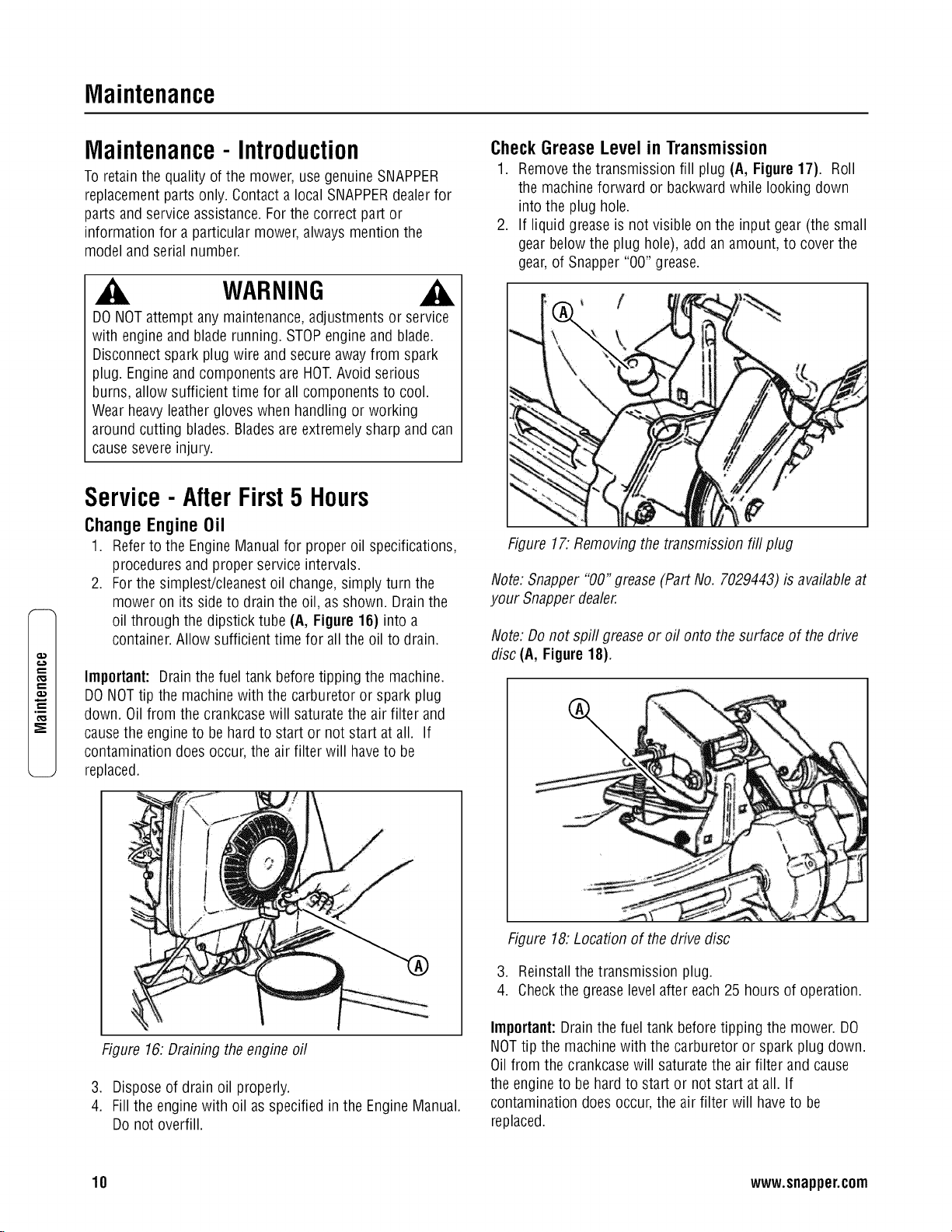
Maintenance
p,,
q-.
.m
_E
Maintenance-Introduction
To retain the quality of the mower, use genuine SNAPPER
replacement parts only. Contact a local SNAPPERdealer for
parts and service assistance.For the correct part or
information for a particular mower, always mention the
model and serial number.
WARNING
DONOT attempt any maintenance,adjustments or service
with engine and blade running. STOPengine and blade.
Disconnect spark plug wire and secure away from spark
plug. Engine and components are HOT.Avoid serious
burns, allow sufficient time for all components to cool.
Wear heavy leather gloves when handling or working
around cutting blades. Bladesare extremely sharp and can
causesevere injury.
Service- After First5 Hours
Change Engine Oil
1. Refer to the EngineManual for proper oil specifications,
procedures and proper service intervals.
2. For the simplest/cleanest oil change, simply turn the
mower on its side to drain the oil, as shown. Drain the
oil through the dipstick tube (A, Figure 16) into a
container. Allow sufficient time for all the oil to drain.
Important: Drain the fuel tank before tipping the machine.
DO NOT tip the machinewith the carburetor or spark plug
down. Oil from the crankcasewill saturate the air filter and
causethe engine to be hard to start or not start at all. If
contamination does occur, the air filter will haveto be
replaced.
CheckGreaseLevel in Transmission
1. Removethe transmission fill plug (A, Figure 17). Roll
the machine forward or backward while looking down
into the plug hole.
2. If liquid grease is not visible on the input gear (the small
gear below the plug hole), add an amount, to cover the
gear, of Snapper "00" grease.
Figure 17. Removing the transmission fill plug
Note: Snapper "00" grease (Part No. 7029443) is available at
your Snapper dealer.
Note: Do not spill grease or oil onto the surface of the drive
disc (A, Figure 18).
%
Figure 16: Draining the engine oil
3. Dispose of drain oil properly.
4. Fill the enginewith oil as specified in the Engine Manual.
Do not overfill.
Figure 18: Location of the drive disc
3. Reinstall the transmission plug.
4. Checkthe grease level after each 25 hours of operation.
Important:Drain the fuel tank before tipping the mower. DO
NOTtip the machine with the carburetor or spark plug down.
Oil from the crankcase will saturate the air filter and cause
the engine to be hard to start or not start at all. If
contamination does occur, the air filter will haveto be
replaced.
10 www.snapper.com

Maintenance(Continued)
WARNING
DONOT attempt any maintenance,adjustments or service
with engine and blade running. STOPengine and blade.
Disconnect spark plug wire and secure away from spark
plug. Engine and components are HOT.Avoid serious
burns, allow sufficient time for all components to cool.
Wear heavy leather gloves when handling or working
around cutting blades. Bladesare extremely sharp and can
causesevere injury.
Check Mower Blade
1. Disconnect the spark plug wire and securethe end away
from the plug.
2. Tilt the mower up on its rearwheels for accessto the
blade cap screw (A, Figure19). Do not tilt the mower
with the spark plug or carburetor down.
Important:Drain the fuel tank before tipping the mower. DO
NOTtip the machine with the carburetor or spark plug down.
Oil from the crankcasewill saturate the air filter and cause
the engineto be hard to start or not start at all. If
contamination does occur, the air filter will haveto be
replaced.
3. Checkthe torque of the bladecap screw. Recommended
torque should be 40 ft. Ibs.
4. Checkthe bladefor sharpness, wear and damage. Refer
to the Section entitled "BladeWear Limits".
Figure 19. Tightening the blade cap screw
Check Engine Drive Belt
1. Visually check the engine drive belt for cracking, fraying,
severedor exposed belt strands. If worn or damaged,
replace the belt before operating the mower.
Check Transmission Poly-V Belt
1. Visually check the poly-v belt for cracking, fraying, sev-
ered or exposed belt strands. If worn or damaged,
replacethe belt before operating the mower.
Service- Periodic
Perform all maintenanceas described in the "Service
Schedule" section of this manual.
Engine
Service the engine according to the engine owner's manual.
Air Filter
Referto the engine owner's manual for service instructions.
EngineOil
Referto the engine owner's manual for service instructions.
StorageProcedure
Referto the Engine Owner's Manual for directions regarding
engine storage preparations. Preparethe mower for "end of
season" storage as follows:
1. Drain the fuel from the fuel tank and let the engine run
until all fuel is out of the carburetor.
2. Disconnect and remove the spark plug wire awayfrom
the spark plug before any other preparations are made!
3. Tapeall openings closed to preventspraying water into
the exhaust or air intakes during washing.
4. Tilt the mower up on its rear wheels and thoroughly
clean the underside of the deck. Do not tilt the mower
with the spark plug or carburetor down. Scrapeaway
any accumulation of grass with a putty knife and/or
wire brush.
5. Lubricate all exposed metal with a light coating of oil to
prevent corrosion.
6. On self-propelled models, disconnect the transfer rod
clip and remove the ground speed control rod before
folding the handles.
7. Loosen the handle knobs. Carefully fold the handles
forward, "flexing" the control cables to prevent cable
damage.
8. Store the mower in a shed or other dry area, protected
from weather.
m.
€'D
11
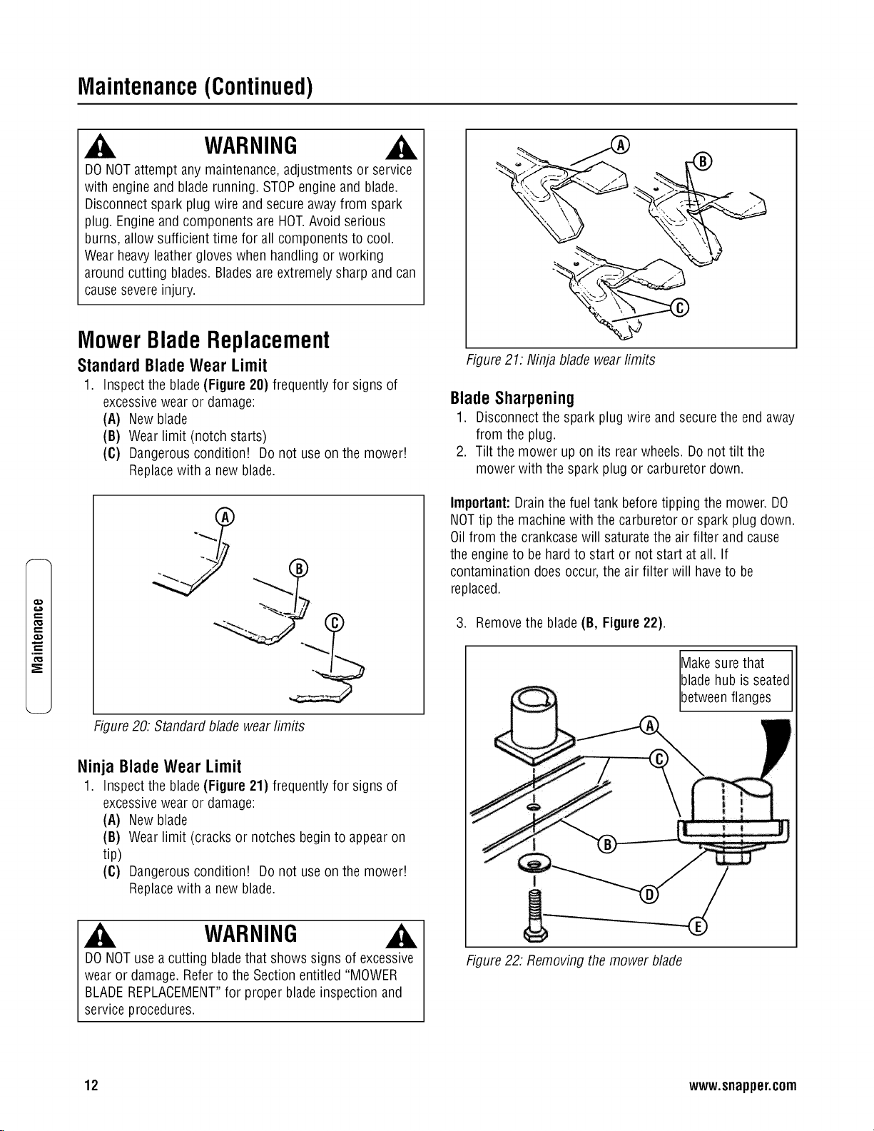
Maintenance(Continued)
,m
_E
WARNING
DONOT attempt any maintenance,adjustments or service
with engine and blade running. STOPengine and blade.
Disconnect spark plug wire and secure away from spark
plug. Engine and components are HOT.Avoid serious
burns, allow sufficient time for all components to cool.
Wear heavy leather gloves when handling or working
around cutting blades. Bladesare extremely sharp and can
causesevere injury.
MowerBladeReplacement
Standard Blade Wear Limit
1. Inspect the blade(Figure 20) frequently for signs of
excessivewear or damage:
(A) New blade
(B) Wear limit (notch starts)
(C) Dangerous condition! Do not use on the mower!
Replacewith a new blade.
Figure 20: Standard blade wear limits
Ninja Blade Wear Limit
1. Inspect the blade(Figure 21) frequently for signs of
excessivewear or damage:
(A) New blade
(B) Wear limit (cracks or notches begin to appearon
tip)
(C) Dangerous condition! Do not use on the mower!
Replacewith a new blade.
WARNING
DONOT use a cutting bladethat shows signs of excessive
wear or damage.Refer to the Section entitled "MOWER
BLADEREPLACEMENT"for proper blade inspection and
service procedures.
Figure 21: Ninja blade wear fimits
BladeSharpening
1. Disconnect the spark plug wire and secure the end away
from the plug.
2. Tilt the mower up on its rear wheels. Do not tilt the
mower with the spark plug or carburetor down.
Important:Drain the fuel tank before tipping the mower. DO
NOTtip the machine with the carburetor or spark plug down.
Oil from the crankcase will saturate the air filter and cause
the engineto be hard to start or not start at all. If
contamination does occur, the air filter will haveto be
replaced.
3. Remove the blade (B, Figure22).
Makesure that
bladehub is seatedI
[betweenfanges J
i
Figure 22: Removing the mower blade
12 www.snapper.com

Maintenance(Continued)
WARNING
DO NOTattempt any maintenance, adjustments or service
with engine and blade running. STOPengineand blade.
Disconnect spark plug wire and secure awayfrom spark
plug. Engineand components are HOT.Avoid serious
burns, allow sufficient time for all components to cool.
BladeSharpening(Continued)
4. Sharpen the bladeon a grinding wheel at an angle of 22
to 28 degrees (B, Figure 23). DO NOTsharpen the blade
beyond the original cutting edge(A).
Do not sharpen
beyond original
cutting edge
Endview of
bladeassembly
Figure 23: Sharpening the mower blade
5. Check blade for balance.If necessary,correct balance by
grinding heavyend of blade.
6. Reinstall blade (B, Figure 22}. Note the correct
assembly order:
(A) Blade hub
(B) Blade
(C) Bladeflange (facing up)
(D) Conewasher (concave side up)
(E) Capscrew
7. Checktorque of blade retaining cap screw.
Recommendedtorque should be 40 ft. Ibs.
Wheel DriveControlAdjustment
(Self-PropelledModelsOnly)
1. The wheel drive control is properly adjusted when there
is 1/16" to 1/8" clearance (G, Figure24) betweenthe
inside of the spring hook (E) and the inside of the clutch
cable eye (C) with the wheel drive control released.
Figure 24: Wheeldrive control adjustment
2. To adjust, unhook the upper spring (D) from the cable
eye and rotate the spring in the direction required to
extend or shorten the spring length.
3. Rehook the upper spring to the cable eye and check
clearance. Repeatthe procedure if required.
Note. Thevinyl spring cover(B) should be kept over the
spring at aft times except for adjustments.
.
If the wheel drive control fails to return quickly to the
"OFF" position when released,check for binding at the
cable holdings located on the side of the right handle.
The upper clip should be located 2" below the upper
knob; the lower clip should be 4" above the lower knob.
The cable should slide freely with the clips installed at
these locations.
m.
€'D
13
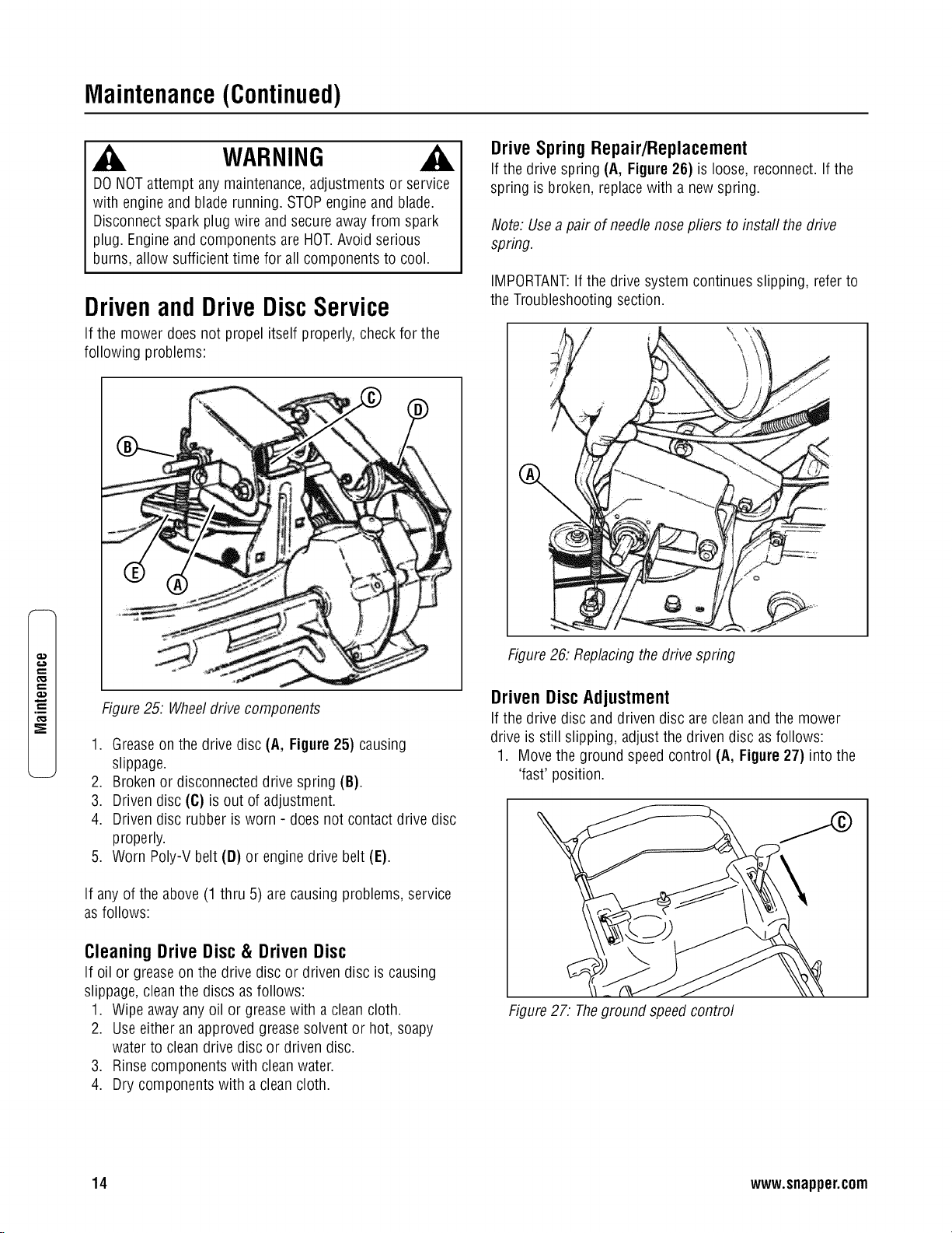
Maintenance(Continued)
e,,,
t_
.m
_E
WARNING
DO NOTattempt any maintenance, adjustments or service
with engine and blade running. STOPengineand blade.
Disconnect spark plug wire and secure awayfrom spark
plug. Engineand components are HOT.Avoid serious
burns, allow sufficient time for all components to cool.
Drivenand DriveDiscService
If the mower does not propel itself properly, check for the
following problems:
Figure 25. Wheel drive components
1. Greaseon the drive disc (A, Figure 25) causing
slippage.
2. Broken or disconnected drive spring (B).
3. Driven disc (C) is out of adjustment.
4. Driven disc rubber is worn - does not contact drive disc
properly.
5. Worn Poly-V belt (D) or engine drive belt (E).
If any of the above (1 thru 5) are causing problems, service
as follows:
Cleaning Drive Disc & Driven Disc
If oil or greaseon the drive disc or driven disc is causing
slippage, clean the discs as follows:
1. Wipe away any oil or grease with a clean cloth.
2. Use either an approved grease solvent or hot, soapy
water to clean drive disc or driven disc.
3. Rinse components with clean water.
4. Dry components with a clean cloth.
DriveSpringRepair/Replacement
If the drive spring (A, Figure 26) is loose, reconnect. If the
spring is broken, replacewith a new spring.
Note: Usea pair of needlenose pliers to install the drive
spring.
IMPORTANT:If the drive system continues slipping, refer to
the Troubleshooting section.
Figure 26: Replacingthe drive spring
Driven Disc Adjustment
If the drive disc and driven disc are clean and the mower
drive is still slipping, adjust the driven disc as follows:
1. Move the ground speed control (A, Figure 27) into the
'fast' position.
Figure 27: Theground speed control
14 www.snapper.com

Maintenance(Continued)
WARNING
DO NOTattempt any maintenance, adjustments or service
with engine and blade running. STOPengineand blade.
Disconnect spark plug wire and secure awayfrom spark
plug. Engineand components are HOT.Avoid serious
burns, allow sufficient time for all components to cool.
Driven Disc Adjustment (Continued)
2. Remove the driven disc spring (A, Figure 28) from the
driven disc assembly (B). Also remove the pin and
washer (C) from the transfer rod (D), and removethe
end of the transfer rod from the hole in the driven disc
assembly.
Figure 28: Adjusting the driven disc
3. Slide the driven disc assembly over to 1/8" (A, Figure
29) from the outside edge of the drive disc (B).
4. Loosen the jam nut (A, Figure 38) securing the transfer
rod (B) to the ball joint (C) on the pivot bracket (D).
5. Turn the rod in or out of the ball joint until the end of the
rod aligns with the hole (E) in the driven disc assembly
from which the rod was removed.
IMPORTANT:Do not move the pivot bracket.
6. Reinstall the rod as removed in Step 2. Move the ground
speed control to the 'slow' position, then back to the
'fast' position. Recheckthe 1/8" measurement described
previously. Readjustas needed.Tighten the nut when
finished.
7. Reinstall the driven disc spring to the driven disc
assembly.
Figure 29: Proper driven disc adjustment
Figure 30: Adjusting the transfer rod
Driven Disc Replacement
If the rubber on the driven disc is badly chunked or worn, it
must be replaced. Install a new driven disc as follows:
1. Removethe pin and washer (C, Figure 28) from the
transfer rod (D), and remove the end of the transfer rod
from the hole in the driven disc assembly.
m.
15
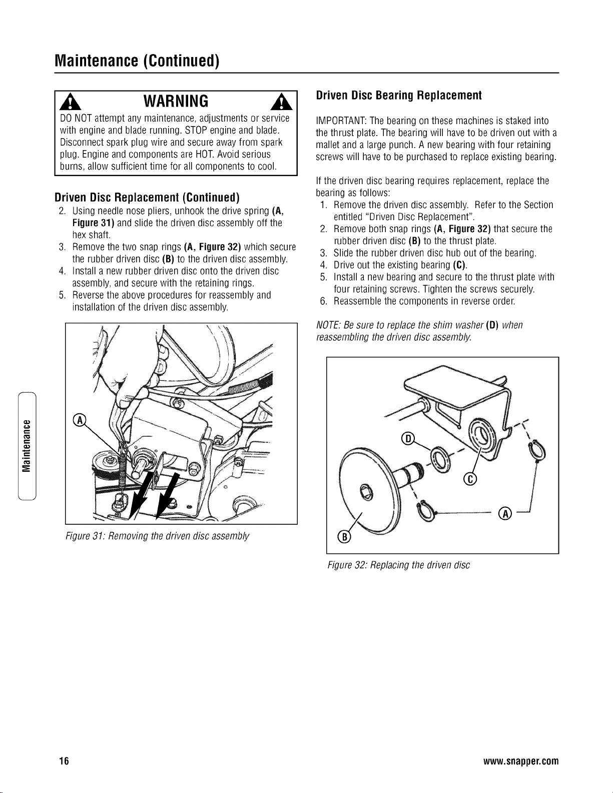
Maintenance(Continued)
e,,,
t_
.m
_E
WARNING
DO NOTattempt any maintenance, adjustments or service
with engine and blade running. STOPengineand blade.
Disconnect spark plug wire and secure awayfrom spark
plug. Engineand components are HOT.Avoid serious
burns, allow sufficient time for all components to cool.
Driven Disc Replacement (Continued)
2. Using needle nose pliers, unhook the drive spring (A,
Figure 31) and slide the driven disc assembly off the
hex shaft.
3. Remove the two snap rings (A, Figure 32) which secure
the rubber driven disc (B) to the driven disc assembly.
4. Install a new rubber driven disc onto the driven disc
assembly, and secure with the retaining rings.
5. Reversethe above proceduresfor reassembly and
installation of the driven disc assembly.
Driven Disc Bearing Replacement
IMPORTANT:The bearing on these machines is staked into
the thrust plate. The bearing will haveto be driven out with a
mallet and a large punch. A new bearing with four retaining
screws will haveto be purchased to replace existing bearing.
If the driven disc bearing requires replacement, replace the
bearing as follows:
1. Removethe driven disc assembly. Refer to the Section
entitled "Driven Disc Replacement".
2. Remove both snap rings (A, Figure 32) that secure the
rubber driven disc (B) to the thrust plate.
3. Slide the rubber driven disc hub out of the bearing.
4. Drive out the existing bearing (C).
5. Install a new bearing and secure to the thrust plate with
four retaining screws. Tighten the screws securely.
6. Reassemblethe components in reverse order.
NOTE:Be sure to replace the shim washer (D) when
reassembfingthe driven disc assembly.
Figure 31. Removing the driven disc assembly
Figure 32: Replacing the driven disc
16 www.snapper.com
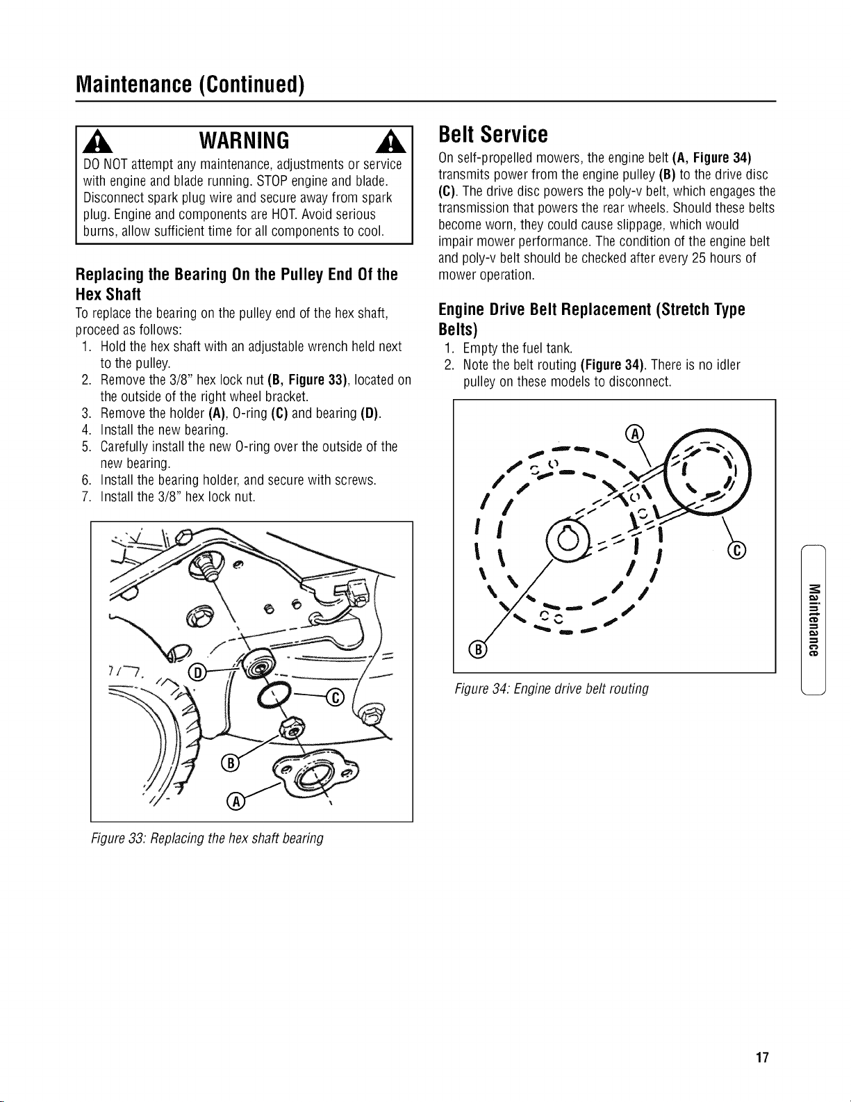
Maintenance(Continued)
WARNING
DO NOTattempt any maintenance, adjustments or service
with engine and blade running. STOPengineand blade.
Disconnect spark plug wire and secure awayfrom spark
plug. Engineand components are HOT.Avoid serious
burns, allow sufficient time for all components to cool.
Replacing the Bearing On the Pulley End Of the
Hex Shaft
To replace the bearing on the pulley end of the hex shaft,
proceed as follows:
1. Hold the hex shaft with an adjustable wrench held next
to the pulley.
2. Remove the 3/8" hex lock nut (B, Figure33), located on
the outside of the right wheel bracket.
3. Remove the holder (A), O-ring (C) and bearing (D).
4. Install the new bearing.
5. Carefully install the new O-ring over the outside of the
new bearing.
6. Install the bearing holder, and secure with screws.
7. Install the 3/8" hex lock nut.
BeltService
On self-propelled mowers, the engine belt (A, Figure 34)
transmits power from the engine pulley (B) to the drive disc
(C). The drive disc powers the poly-v belt, which engages the
transmission that powers the rearwheels. Should these belts
become worn, they could cause slippage,which would
impair mower performance. The condition of the engine belt
and poly-v belt should be checked after every 25 hours of
mower operation.
Engine Drive Belt Replacement (Stretch Type
Belts)
1. Empty the fuel tank.
2. Note the belt routing (Figure 34). There is no idler
pulley on these models to disconnect.
f ,.. o "_ \//>_ "l,
\% \/ /I//
Figure 34. Engine drive belt routing
i.
€'D
€'D
Figure 33. Replacingthe hex shaft bearing
17

Maintenance(Continued)
e,,,
t_
.m
_E
WARNING
DO NOTattempt any maintenance, adjustments or service
with engine and blade running. STOPengineand blade.
Disconnect spark plug wire and secure awayfrom spark
plug. Engineand components are HOT.Avoid serious
burns, allow sufficient time for all components to cool.
EngineDrive Belt Replacement(StretchType
Belts- Continued)
IMPORTANT:Drain the fuel tank before tipping the mower.
DO NOT tip the machinewith the carburetor or spark plug
down. Oil from the crankcase will saturate the air filter and
causethe engine to be hard to start or not start at all. If
contamination does occur, the air filter will haveto be
replaced.
3. Remove the driven disc. Referto the Section entitled
"Driven Disc Replacement"for driven disc removal
procedure.
4. Drain the fuel tank before tipping the mower. Do not tilt
the mower with the spark plug or carburetor down. Tilt
the mower up on its rear wheels and removethe blade
and bladehub. Assistance from another person may be
necessaryto hold the mower in the tilted position.
5. Hold the slotted end of the drive disc bolt (B, Figure 35)
with a screwdriver and remove the nut (G) and internal
tooth lock washer (F).
6. Remove the belt cover, located under the deck.
7. Lift the drive disc (A) up and remove the worn belt.
8. Loop one end of the new belt over the engine pulley and
insert the other end through the slot in the deck.
9. Loop the belt around the pulley on the bottom of the
drive disc.
10.Reinstall the drive disc and retaining hardware.
IMPORTANT:1) The square shoulder of the drive disc bolt
must fit into the square hole of the bushing. 2) The square
end of bushing must fit into the bracket slot.
11.Reinstall the belt cover and tighten the bolts securely.
12.Reinstall the blade hub and cutter blade. Recommended
torque for the blade cap screw is 40 ft. Ibs.
------4b
)
Figure 35. Removing the drive disc
Transmission Poly-V Belt Replacement
1. Remove the driven disc. Referto the Section entitled
"Replacing Driven Disc Rubber Ring".
2. Note the routing of the old belt around the three pulleys
before removing it.
3. Place the new Poly-V Belt (A, Figure 36) over the end of
the hex shaft (B) and onto the drive pulley (C).
4. Work the belt onto the top of the idler pulley (D).
5. Twist the belt sideways and pull it upward betweenthe
differential bracket (E) and driven pulley (F) and then
down into the pulley groove. Make sure the Poly-V Belt
is above the belt guide (G).
J
Figure 36. Poly-v belt routing
18 www.snapper.com

Maintenance(Continued)
BatteryService
New BatteryPreparation
1. Remove the battery from the carton.
2. Placethe battery in a well ventilated area on a level non-
concrete surface.
3. Remove the battery cell caps. Fill the cells as required
with electrolyte (supplied with battery) to the proper
level. Filling the battery with electrolyte will bring the
battery to 80% charged state.
4. With the cell caps removed, connect the battery charger
to the battery terminals; REDto positive (+) and BLACK
to negative (-) terminal.
IMPORTANT:Neverplace anything in the battery other than
the specified electrolyte.
5. Slow charge the battery at 1 amp for 2 hours to bring
the battery to full charge.
6. After charging, check the level of electrolyte and add as
neededto bring to the proper fluid level.
7. Reinstall the cell caps.
8. Install the battery into the power unit.
9. Connect the positive (+) cable (red) first, from the wiring
harness to the positive terminal (+) on the battery using
the bolt and nut provided in the hardware bag. Connect
the negative (-) cable (black) last, to the negativetermi-
nal (-) on the battery using the bolt and nut. Apply a
small amount of grease over the terminals to prevent
corrosion.
WARNING
DONOToverfill batterywithelectrolyte.Shieldthe positive
terminalwithterminalcoverlocatedonbatteryharness.This
preventsmetalfrom touchingthe positiveterminal,which could
causesparks.Theelectrolyte(acid)producesa highlyexplosive
gas.Keepall sparks,flameandfire awayfrom areawhen
chargingbatteryor whenhandlingelectrolyteor battery.
Electrolyte(acid)is a highlycorrosiveliquid.Weareyeprotection.
Washaffectedareasimmediatelyafterhavingeyeor skincontact
with electrolyte(acid).Batteryacid is corrosive.Rinseemptyacid
containerswithwaterandmutilatebeforediscarding.If acidis
spilledon battery,bench,or clothing,etc.,Flushwith clearwater
andneutralizewith bakingsoda.Neverattemptto chargebattery
while installedonthe walk behind.Neveruse"BOOST"chargers
onthe battery.
BatteryService
1. Removethe battery.
2. Place the battery in a well ventilated areaon a level sur-
face.
3. Using distilled water, refill the cells as required to cover
the cell plates.
4. With the cell caps removed, connect the battery charger
to the battery terminals. Redto positive (+) terminal
and black to negative (-) terminal.
5. Slow charge the battery at 1 amp for 10 hours.
6. If the battery will not accept a charge or is partially
charged after 10 hours of charging at 1 amp, replace
with a new battery.
BatteryStorage
If the Walk Behindis to be stored out of season on its rear
bumper, it is recommendedthe battery be removed, charged
and stored.
1. Removethe battery.
2. Perform battery service.
3. Bring the battery to full charge, if required.
4. Store the battery in an area awayfrom the Walk Behind
on a wood surface. DO NOT STOREBATTERYON A
CONCRETESURFACE.
Battery Testing
There are two types of battery tests: Unloaded and Loaded.
The unloaded test is the procedure that will be discussed. It's
the simplest and most commonly used. An unloadedtest is
made on a battery without discharging current. To perform
unloaded testing, check charge condition using either a
hydrometer or voltmeter.
.
.
Using a voltmeter, voltage readings appear instantly to
show the state of charge. Rememberto hook the posi-
tive leadto the battery's positive terminal, and the nega-
tive leadto the negative terminal.
A hydrometer measuresthe specific gravity of each cell.
The specific gravity tells the degree of charge; generally,
a specific gravity of about 1.265 to 1.280 indicates full
charge. A readingof 1.230 to 1.260 indicates the battery
should be charged. The chart below shows the charge
level as measured by syringe float hydrometer, digital
voltmeter and five ball hydrometer.
Methodsof CheckingBattery Condition
State of Charge SyringeHydrometer Digital Voltmeter Five Ball Hydrometer
100% Chargedw/Sulfate Stop 1.280 12.80v FiveBalls Floating
100% Charged 1.265 12.60v Four Balls Floating
75% Charged 1.210 12.40v Three Balls Floating
50% Charged 1.160 12.10v Two Balls Floating
25% Charged 1.120 11.90v One Ball Floating
0% Charged Lessthan 1.100 Lessthan 11.80v Zero Balls Floating
m,
¢D
€'D
19
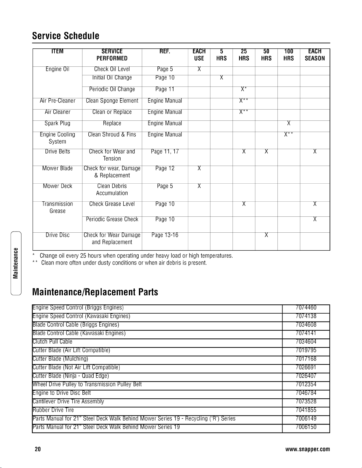
,m
ServiceSchedule
ITEM
Engine Oil
Air Pre-Cleaner
Air Cleaner
Spark Plug
EngineCooling
System
Drive Belts
Mower Blade
Mower Deck
Transmission
Grease
Drive Disc
SERVICE
PERFORMED
Check Oil Level
Initial Oil Change
Periodic Oil Change
CleanSponge Element
Cleanor Replace
Replace
CleanShroud & Fins
Check tor Wear and
Tension
Check for wear, Damage
& Replacement
Clean Debris
Accumulation
CheckGrease Level
Periodic GreaseCheck
Check for Wear Damage
and Replacement
REF.
Page5
Page10
Page11
EngineManual
EngineManual
EngineManual
EngineManual
EACH
USE
5
HRS
X
Page11, 17
Page12 X
Page5 X
Page10
Page10
Page13-16
* Changeoil every 25 hours when operating under heavy load or high temperatures.
** Cleanmore often under dusty conditions or when air debris is present.
25
HRS
X_
X**
X**
5O
HRS
lOO
HRS
X
X**
Maintenance/ReplacementParts
EngineSpeed Control (Briggs Engines)
EngineSpeed Control (KawasakiEngines)
BladeControl Cable (Briggs Engines)
BladeControl Cable (KawasakiEngines)
Clutch Pull Cable
Cutter Blade(Air Lift Compatible)
Cutter Blade(Mulching)
Cutter Blade(Not Air Lift Compatible)
Cutter Blade(Ninja - Quad Edge)
Wheel Drive Pulley to Transmission Pulley Belt
Engineto Drive Disc Belt
Cantilever Drive Tire Assembly
Rubber Drive Tire
Parts Manual for 21" Steel Deck Walk Behind Mower Series 19 - Recycling ('R') Series
Parts Manual for 21" Steel Deck Walk Behind Mower Series 19
EACH
SEASON
X
X
X
7074460
7074138
7034608
7074141
7034604
7019795
7017168
7026691
7026407
7012354
7046784
7073528
7041855
7006149
7006150
20 www.snapper.com

Troubleshooting
PROBLEM
Engine Will Not Start Using
Recoil Starter
Engine Will Not Start (Electri(
Start Models)
Engine Stalls or Stops After
Running
Engine Loses Power
Excessive Vibration
IVlowerWill Not IVloveLoss
Of Traction (Self-Propelled
Models)
Cutting Grass Improperly
Poor Grass Discharge
Oil Leaking
PROBABLECAUSE
1. Fuel tank empty. 1.
2. Engine needs choking or priming. 2.
3. Spark plug wire disconnected. 3.
4. Kawasaki Engines Only - Fuel shut-oft in the 'Off' 4.
)osition.
1. Fuel tank empty. 1.
2. Engine needs choking or priming. 2.
3. Spark plug wire disconnected. 3.
4. Wiring harness disconnected. 4.
5. Battery dead. 5.
6. Kawasaki Engines Only - Fuel shut-off in the 'Off' 6.
)osition.
1. Blade control is released or is not being held
securely against handle.
2. Fuel tank empty.
3. Engine air pre-cleaner and or air cleanerdirty.
4. Spark plug detective or gap set improperly.
CORRECTIVEACTION
Fill tuel tank with tresh fuel.
Choke/Prime. Check Engine IVlanualfor Instructions.
Place spark plug wire onto spark plug.
lurn Fuel shut-oft to 'On' position.
Fill tuel tank with tresh tuel.
Choke/Prime. Check Engine Manual for Instructions.
Place spark plug wire onto spark plug.
Connect wiring harness.
Charge or replace battery.
lurn Fuel shut-off to 'On' position.
1. Blade control should be held securely against handle
at all times during operation of mower.
2. Fill with fuel to proper level.
3. Clean tree of all debris.
4. Service spark plug.
5. Water, debris or stale fuel in fuel system. 5.
6. Kawasaki Engines Only - Fuel shut-oft in the 'Ott' 6.
)osition.
1. Engine air pre-cleaner or air cleaner dirty. 1.
2. Spark plug faulty. 2.
3. Water, debris or stale fuel in fuel system. 3.
1. Damaged, out of balance or bent mower blade. 1.
2. Loose blade components. 2.
3. Loose or missing air Iitt (it equipped). 3.
4. Lumpy or trayed belt. 4.
1. Build-up of debris on or around wheel drive 1.
components.
2. Driven disc slipping.
3. Drive belt requires replacement.
4. Damaged transmission.
1. Cutting height too low or high.
2. Engine speed too slow.
3. Forward ground speed too fast.
4. lerraced cut, side to side.
5. Excessive deck pitch, front to rear.
6. Cutting blade dull or damaged.
1. Engine speed too fast. 1.
2. Forward speed too tast. 2.
3. Grass is wet. 3.
4. Excessively worn or damaged blade. 4.
5. Build up of grass clippings and debris under deck. 5.
6. Improper blade installed on deck. 6.
7. Blade installed improperly on deck. 7.
1. Leaking engine case. 1.
2.
Drain and clean fuel system.
lurn Fuel shut-oft to 'On' position.
Clean or replace tilters.
Service spark plug.
Drain and clean fuel system.
Service mower blade.
Service and tighten loose parts.
Replaceair lifts, lighten to proper torque.
Replace belt.
Clean debris.
2. Clean or replace driven disc.
3. Replace drive belt.
4. Contact authorized SNAPPERdealer.
1. Adjust cutting height.
2. Move engine speed control to 'Fast' position.
3. Move ground speed control to a slower speed.
4. Adjust height of cut with height adjust levers.
5. Adjust height of cut with height adjust levers.
6. Sharpen cutting edges or replace blade.
Move engine speed control to 'Fast' position.
IVloveground speed control to a slower speed.
IVlowwhen grass is dry.
Service mower blade.
Clean deck.
Install proper SNAPPEHblade.
Install blade properly.
Contact authorized SNAPPERdealer.
Check and tighten drain plug.
3. IVlakesure dip stick or oil tiller cap is securely in
)lace.
=3"
m.
21

t_
,m
2 YEAR LIMITED WARRANTY
For two (2) years from purchase date for the original purchaser's residential, non-commercial use, SNAPPER,through any
authorizedSNAPPERdealerwill replace,free of charge (except for taxes where applicable), any part or parts found upon
_xamination by the factory at McDonough, Georgia,to be defective in material or workmanship or both.
For ninety (90) days from purchasedate for the original purchaser's commercial, rental, or other non-residential use, SNAP-
PER,through any authorized SNAPPERdealer will replace,free of charge,any part or parts found upon examination by the
[actory at McDonough, Georgia,to be defective in material or workmanship or both.
&ll transportation costs incurred by the purchaser in submitting material to an authorized SNAPPERdealerfor replacement
underthis warranty must be paid by the purchaser.
This warranty does not apply to certain transmissions, to engines and their components, and batteries, as these items arewar-
ranted separately. This warranty does not apply to parts that havebeen damaged by accident, alteration, abuse, improper
lubrication, normal wear, or other causebeyond the control of SNAPPER.This warranty does not cover any machine or com-
ponent part that has been altered or modified changing safety, performance, or durability.
Batteries have a one (1) year warranty period with free replacement if required for one (1) year from the original purchase
date.SNAPPERwill not be responsible for any installation cost incurred. The battery warranty only covers original equipment
batteries and does not cover damageto the battery or machine caused by neglect or abuse, destruction by fire, explosion,
[reezing, overcharging, improper maintenance, or use of improper electrolyte.
There is no other express warranty.
DISCLAIMMEROFWARRANTY
Implied warranties, includingthoseof merchantabilityand fitness for a particular purpose, are limited to two (2) years
[rom purchasedate for the original purchaser'sresidential or other non-commercialuse, and ninety(90) daysfrom pur-
chase for the original purchaser'scommercial, rental or other non-residentialuse, and to the extent permittedby law, any
andall implied warranties are excluded. This is the exclusiveremedy. Liabilities for consequentialdamages, underany
andall warrantiesare excluded.
Somestates do not allow limitations on how long an implied warranty lasts, or do notallow the exclusionor limitation of
incidentalor consequentialdamages, so the abovelimitation or exclusionmay notapply to you.
Thiswarranty gives you specific legal rights, and you may also have other rights which vary from state to state.
WARNING:THE USEOF REPLACEMENTPARTSOTHERTHAN GENUINESNAPPERPARTSMAY IMPAIR THESAFETYOF
SNAPPERPRODUCTSAND WILL VOIDANY LIABILITYANDWARRANTYBYSNAPPERASSOCIATEDWITH THE USEOF
SUCHPARTS.
IMPORTANT:
Pleasefill out the attached SNAPPERProduct Registration Card immediately and mail to:
Snapper'sProductRegistrationCenter, P.O.Box1379, IVlcDonough,Georgia30253
22 www.snapper.com

04
4- SLOPE GUIDE
........ :..../.b" DE_D_... SIGHT AND HOLD THIS GUIDE LEVEL WITH A VERTICAL TREE,
I ".... -'..'.._S A CORNER OF A STRUCTURE, A POWER LINE POLE, OR A FENCE.
j ........................
...... .....................
!
I
I
Operate a walk-behind mower
across the face of slopes,
never up or down slopes.
10 DEGREES 15 DEGREES
Operate a riding mower
up or down slopes, never
across the face of slopes.
On a riding mower to determine if a slope is safe to mow: (1) disengage the blade(s), (2) put the unit in reverse, and (3) try to back straight up the
slope. If you can back up the slope, it is generally safe to mow. However, if you do not feel safe, or if you are not completely sure, use this guide
anddo not mow a slope that is greater than 15 degrees. If the riding mower is used with a pull-behind or rear mounted attachment,
do not operate the und on a slope that is greater than 10 degrees.
A 15 degree slope is a hill that increases in height at approximately 2.5 feet in 10 feet.
A 10 degree slope is a hill that increases in height at approximately 1.7 feet in 10 feet.
Use extreme care at all times, and avoid sudden turns or maneuvers. Follow other instructions in this manual for safety in mowing on
slopes. Operate a riding mower up or down slopes, never across the face of slopes. Operate a walk-behind mower across the face
of slopes, never up or down slopes. Use extra care when operating on or near slopes and obstructions.
................................. _U'T_E'R_fO'U§E'_GP__&_D'E.................................

Notes
24 www.snapper.com

Notes
25

21" STEELDECK
WALKMOWERS
SERIES19
Product Specifications
Deck Size
Height of Cut
Transmission Type (Self-Propelled Models)
Ground Speed (Self-Propelled Models)
Engine Power - Briggs Quantum / DOV
Engine Power- Briggs Intek
Engine Power- Kawasaki
Engine Displacement - Briggs DOV
Engine Displacement - Briggs Quantum / Intek
Engine Displacement - Kawasaki
Fuel Tank Capacity - Briggs (all)
Fuel Tank Capacity - Kawasaki
21 in
1,25- 4 in
Gear
1 -4 mph
6.50ft-lbs (gross)
8.75ft-lbs (gross)
6.0 hp (gross)
160cc
190cc
180cc
1.6 qt
2,1 qt
CommonServiceParts
Cutter Blade(Ninja - Quad)
Drive Belt (Engine)
Drive Belt (Transmission)
Parts Manual (Recycling)
Parts Manual
Part Number
7026407
7046784
7012354
7006149
7006150
EnginePower RatingInformation:The gross power rating for individual gas engine models is labeled in accordancewith
SAE(Society of Automotive Engineers) code J1940 (Small Engine Power & Torque Rating Procedure), and rating perform-
ance has been obtained and corrected in accordancewith SAEJ1995 (Revision 2002-05). Torque values are derived at 3060
RPM; horsepower values are derived at 3600 RPM. Actual gross engine power will be lower and is affected by, among other
things, ambient operating conditions and engine-to-engine variability. Given both the wide array of products on which engines
are placed and the variety of environmental issues applicable to operating the equipment, the gas enginewill not develop the
rated gross power when used in a given piece of power equipment (actual "on-site" or net power). This difference is due to a
variety of factors including, but not limited to, accessories (air cleaner,exhaust, charging, cooling, carburetor, fuel pump,
etc.), application limitations, ambient operating conditions (temperature, humidity, altitude), and engine-to-engine variability.
Due to manufacturing and capacity limitations, Briggs & Stratton may substitute an engine of higher rated power for this
Series engine.
SnapperProducts
535 Macon Street
McDonough, GA30253
26
1-000-935-2967
www.snapper.com

SafetyInstructions& Operator'sManual for
21" STEELDECK
WALKMOWERS
SERIES19
f
Models
RP2167519BD V (7800066)
RP2187519BV (7800172)
RP2187519BVE (7800173)
RP216019KWV (7800199)
2167519B
P2167519B
P2187519BV
P2187519BVE
P216019KWV
N2167519B
(7800217)
(7800218)
(7800176)
(7800178)
(7800193)
(7800133)
NP2167519B(7800134)
NP2187519BV (7800131)
J
NOTE:Specifications are correct at time of printing and are subjectto changewithout notice.
* Actualsustained engine power will likely he lower due to operating limitations and environmental factors. Please refer to 'Engine Power Rating Information' for
further details.
Manual No. 7101587 (I.R. 9/25/2007)
TP lO0-5289-1R-WB-N

ThankYou for purchasingthis quality-built Snapper product. We're pleasedthat you placedyour
confidence in the Snapper brand. When operatedand maintained according to the instructions in this
manual, your Snapper product will provide many years of dependableservice.
This manual containssafety information to makeyou awareof the hazardsand risks associatedwith the
machine and how to avoid them. This machine is designed and intended only for finish cutting of
established lawns and is not intendedfor any other purpose. It is important that you read and understand
these instructions thoroughly before attempting to start or operatethis equipment. Savethese
instructions for future reference.
PRODUCT REGISTRATION
IMPORTANT: KEEPTHIS INFORMATION FOR YOUR PERSONAL RECORDS
(Complete the following information on your Snapper purchase)
Date of Purchase
Retailer
Retailer's Phone Number
Equipment
Model Number
Serial Number
Engine
Model .Type. Trim
It is very importantthat youregisteryourpurchasewith Snapperto ensurewarrantycoverage.Please
mail yourproductregistrationcardto:
Snapper at P.O. Box 777, McDonough, Georgia 30253.
Or you may registeronline at www.snapper.com.
Youcan contactusat our website, or if you wouldlike to speakwith a CustomerService
Representative,call usat the SnapperCustomerRelationsCenterat 1-800-935-2967. Forfaster
serviceplease haveyourSerial Numberand Model Numberavailable.
SNAPPERis a trademarkof
Simplicity Manufacturing,Inc.
PortWashington,WI, USA.
Briggs& StrattonYard Power Products Group
Copyright© 2007, Briggs& StrattonCorporation
Milwaukee, WI, USA. All RightsReserved.

Tableof Contents
Operator Safety ................................................ 2
Important Operator Safety Instructions .................................. 2
Featuresand Controls ........................................... 4
Operation .................................................... 5
Pre-Start Checklist .................................................. 5
Starting & Stopping Engine & Blades .................................... 5
Propelling Mower ................................................... 6
Handle Height Adjustment ............................................ 6
Cutting Height Adjustment ............................................ 7
Recycling Operation ................................................. 7
Removing the Recycling Cover ......................................... 7
Installing the Discharge Deflector ....................................... 8
Installing the Grass Bag Adapter ........................................ 8
Installing the Grass Bag .............................................. 9
Maintenance ................................................. 10
ChangeEngine Oil .................................................. 10
CheckTransmission Grease .......................................... 10
Check Mower Blade ................................................ 11
Check Engine Drive Belt ............................................. 11
CheckTransmission Belt ............................................. 11
Service - Periodic .................................................. 11
Engine ........................................................... 11
Air Filter ......................................................... 11
Engine Oil ........................................................ 11
Storage Procedure ................................................. 11
Mower Blade Replacement ........................................... 12
BladeSharpening .................................................. 12
Wheel DriveControl Adjustment ....................................... 13
Driven and Drive Disc Service ......................................... 14
Belt Service ....................................................... 17
Engine Drive Belt Replacement ........................................ 17
Transmission Belt Replacement ....................................... 18
Battery Service .................................................... 19
Service Schedule ................................................... 20
Troubleshooting............................................... 21
Warranty .................................................... 22
WARNING
Battery posts, terminals and related accessoriescontain
lead and lead compounds, chemicals known to the State of
Californiato cause cancer and birth defects or other
reproductive harm. Wash hands after handling.
WARNING
Engineexhaust, some of its constituents, and certain
vehicle components contain or emit chemicals known to
the State of California to cause cancer or other reproductive
harm.
CD
"11
CD
CD
t_
,-1
t_
CD
mo
,-1
CD
,-1
,-1
CD
,..z.
--z
CD
t_
x,.,
,A
ImportantOperatorSafetyInstructions
WARNING:This powerful cutting machine is capable of amputating hands and feet and can throw objects
that can cause injury and damage! Failureto comply with the following SAFETYinstructions could result in
serious injury or death to the operator or other persons. The owner of the machine must understand these
instructions and must allow only persons who understand these instructions to operate machine. Each
person operating the machine must be of sound mind and body and must not be under the influence of any
substance,which might impair vision, dexterity or judgment. If you have any questions pertaining to your
machinewhich your dealer cannot answer to your satisfaction, call or write the Customer Service
Departmentat SNAPPER,IVIcDonough,Georgia 30253. Phone: (1-800-935-2967).
Protection for Children
Tragic accidents can occur if the operator is not alert to the
presenceof children. Children are often attracted to the
machine andthe mowing activity. Never assume that
children will remain where you last saw them.
1. KEEPchildren out of the mowing area and under the
watchful care of a responsible adult other than the operator.
2. DO NOT allow children in yard when machine is operated
andturn machine OFFif anyone enters the area.
3. DO NOT allow pre-teenagechildren to operate machine.
4. ALLOW only responsible adults & teenagerswith mature
judgment under close adult supervision to operate machine.
5. DO NOT pull mower backwards unless absolutely
necessary.LOOKand SEEbehind and down for children,
pets and hazards before and while backing.
6. USEEXTRACAREwhen approaching blind corners,
shrubs, trees, or other objects that may obscure vision.
SlopeOperation
1. Slopes are a major factor relatedto slip and fall acci-
dents, which can result in severe injury. All slopes require
extra caution. If you feel uneasyon a slope, DO NOT mow
it.
2. Mow across slopes, never up-and-down. Exercise
extreme CAUTIONwhen changing directions on slopes. DO
NOTmow steep slopes or other areas where stability or
traction is in doubt. Referto the Slope Guide at the end of
this manual.
3. Useextra care with grass catchers or other attachments;
these affect the handling and the stability of the machine.
Preparation
1. Read,understand, and follow instructions and warnings
in this manual and on the mower, engine and attachments.
Know the controls and the proper use of the mower before
starting.
2. Only mature, responsible persons shall operate the
machine and only after proper instruction.
3. Data indicates that operators age 60 and above, are
involved in a large percentageof mower-related injuries.
Theseoperators should evaluatetheir ability to operate the
mower safely enough to protect themselves and others
from serious injury.
Preparation
(ContinuedFrom Previous Column)
4. Handle fuel with extra care. Fuels are flammable and
vapors are explosive. Useonly an approved fuel container.
DO NOT remove fuel cap or addfuel with engine running.
Add fuel outdoors only with engine stopped and cool. Clean
spilled fuel and oil from machine. DO NOTsmoke.
5. Checkthe areato be mowed and remove all objects such
as toys, wire, rocks, limbs and other objects that could
cause injury if thrown by blade or interfere with mowing.
Also note the location of holes, stumps, and other possible
hazards.
6. Keep people and pets out of the mowing area.
Immediately,STOP Blade,Stop engine and Stop mower if
anyone entersthe area.
7. Checkshields, deflectors, switches, blade controls and
other safety devices frequently for proper operation and
location.
8. Make sure all safety decals are clearly legible. Replace if
damaged.
9. Protect yourself when mowing and wear safety glasses, a
dust mask, long pants, and substantial footwear. DO NOT
mow barefooted or with sandals.
10. Know how to STOPbladeand engine quickly in
preparation for emergencies.
11. Use extra care when loading or unloading the machine
into a trailer or truck.
12. Checkgrass catcher components frequently for signs of
wear or deterioration and replaceas neededto prevent
injury from thrown objects going through weak or torn
spots.
Safe Handling of Gasoline
To avoid personal injury or property damage, use extreme
care in handling gasoline. Gasoline is extremely flammable
and the vapors are explosive.
1. Extinguish all cigarettes, cigars, pipes and other sources
of ignition.
2. Use only an approved fuel container.
3. DO NOT remove fuel cap or add fuel with the engine
running. Allow the engine to cool before refueling.
4. DO NOT refuel the machine indoors.
5. DO NOT store the machine or fuel container inside where
there is an open flame, spark or pilot light such as on a
water heater or other appliances.
2 www.snapper.com

ImportantOperatorSafetyInstructions(Continued)
Safe Handling of Gasoline
(ContinuedFromPrevious Page)
6. DO NOTfill fuel containers inside a vehicle or on a truck
or trailer bed with a plastic liner. Always placethe contain-
ers on the ground away from the vehicle before filling.
7. Remove gas-powered equipment from the vehicle or
trailer and refuel it on the ground. If this is not possible,
then refuel equipment using a portable container, rather
than a gasoline dispenser nozzle.
8. DO NOT start gas powered equipment in enclosed vehi-
cles or trailers.
9. Keepthe nozzle in contact with the rim of the fuel tank or
container opening at all times until fueling is complete. DO
NOTuse a nozzle lock-open device
10. If fuel is spilled on clothing, change clothing
immediately.
11. DO NOT overfill a fuel tank. Replacefuel cap and tighten
securely.
Operation
1. DO NOT put hands or feet near or under rotating parts.
Keepclear of discharge areawhile engine is running.
2. STOPenginewhen crossing gravel drives, walks, or
roads, and under any conditions where thrown objects
might be a hazard.
3. Mow only in daylight or good artificial light.
4. DO NOT operate mower while under the influence of
alcohol or drugs.
5. After striking a foreign object or if mower vibrates
abnormally, STOPthe engine, disconnect and secure spark
plug wire. Inspect the mower for any damage and repair the
damage before starting.
6. DO NOT mow near drop offs, ditches or embankments.
Operator could lose footing or balance.
7. STAYALERTfor holes and other hidden hazards.Tall
grass can hide obstacles. Keepawayfrom ditches,
washouts, culverts, fences and protruding objects.
8. DO NOT mow on wet grass. Always be sure of your
footing. Keep a firm hold on the handleand walk, never run.
Slipping could cause injury.
9. ALWAYSstay behind handlewhen engine (motor) is
running.
10. DO NOT leavethe machine with the engine running.
STOPBLADEand STOPENGINEbefore leaving the opera-
tors position for any reason.
11. Before cleaning, repairing or inspecting make certain
engine, blade and all moving parts haveSTOPPED.
Disconnect and secure spark plug wire away from plug to
prevent accidental starting.
12. STOPengineand wait until the bladecomes to com-
plete STOPbefore removing grass bag and/or clearing
grass.
Operation
(ContinuedFrom Previous Column)
13. DO NOT operate mower without the entire grass catch-
er, or guards in place discharge guard, rearguard or other
safety devices in place and working. DONOT point dis-
charge at people, passing cars, windows or doors.
14. DO NOT discharge material against a wall or obstruc-
tion. Material may ricochet back towards the operator.
15. Slow down before turning.
16. Watch out for traffic when near or crossing roadways.
17. DO NOT operate engine in enclosed areas. Engine
exhaust gasescontain carbon monoxide, a deadly poison.
18. Only use accessories approved by the manufacturer.
See manufacturer's instructions for proper operation and
installation of accessories.
Maintenanceand Storage
1. DO NOT store mower or fuel container inside where
fumes may reach an open flame, spark or pilot light such as
in awater heater,furnace, clothes dryer or other gas appli-
ance. Allow engine to cool before storing machine in an
enclosure. Store fuel container out of reach of children in a
well ventilated, unoccupied building.
2. Keep mower and engine free of grass, leaves or excess
grease to reduce fire hazardand engine overheating.
3. When draining fuel tank, drain fuel into an approved
container outdoors and away from open flame.
4. Keep all bolts, especially blade bolts, nuts and screws
properly tight. Checkthat all cotter pins are in proper
position.
5. Always provide adequateventilation when running
engine. Engineexhaust gasescontain carbon monoxide, a
deadly poison.
6. Service engine and make adjustments only when engine
is stopped. Removed spark plug wire from spark plug and
secure wire away from spark plug to prevent accidental
starting.
7. DO NOT change engine governor speed settings or
overspeed engine.
8. Checkgrass bag assembly frequently for wear or
deterioration to avoid thrown objects and exposure to
moving parts. Replacewith new bag if loose seams or tears
are evident. Replaceslider or bag adapter if broken or
cracked.
9. Mower blades are sharp and can cut. Wrap the blades or
wear heavy leather gloves and use CAUTIONwhen handling
them.
10. DO NOTtest for spark by grounding spark plug next to
spark plug hole; spark plug could ignite gas exiting engine.
11. Havemachine serviced by an authorized SNAPPER
dealer at least once ayear and havethe dealerinstall any
new safety devices.
12. Use only genuine SNAPPERreplacement parts to
assure that original standards are maintained.

Featuresand Controls
IMPORTANT
The figures and illustrations in this manual are provided
for reference only and may differ from your specific
model. Contactyour Snapper dealer if you have questions.
x,...
0.1
ii
FeaturesandControls
A. Oil Fill Capand Dipstick
B. Fuel Filler Cap
C. RecyclingCover
D. Rear Height Adjustment Latch (2)
E. Front Height Adjustment Latch (2)
F.
G.
H.
I.
J.
K.
Engine Primer (Not all models)
BladeControl
Rope Start Handle
Ground SpeedControl
Drive Wheel Control
EngineSpeedControl
4 www.snapper.com

Operation
Pre-StartCheckList
Make the following checks and perform the service required
before each start-up.
1. Checkthe guards, deflectors, grass bag, adapter, and
covers to make sure all are in place and securely
tightened.
2. Checkthe blade control (A, Figure 1), wheel drive
control (B), and ground speed control (C) to insure they
work freely.
Figure 1. Mower controls
3. Checkthe cutting height. Adjust to the desired height.
Refer to the Section entitled 'Cutting Height Adjustment'.
4. Checkthe engineoil (A, Figure 2) and add oil as needed
to bring the level up to the full mark. Refer to the Engine
Owner's Manual for oil specifications.
Startingand Operation
Engine and Blade (Briggs Quantum and Intek
Series Engines)
1. Move the engine speed control to the fast ('Rabbit')
position.
2. Push the primer button (A, Figure 3) three times to
start a cold engine.
NOTE: Theprimer should not be required to restart a warm
engine.
NOTE:Briggs QuantumSeries engines are equipped with a
ReadyStartTMfeaturd and thus do not feature a primer
button.
Figure 3: Engine primer
3. Pull the blade control (A, Figure 4) against the handle.
4. Start the mower:
Manual Start Models: Pullthe rope start handle (B)
to crank the engine.
ElectricStart Models: Insertthe key(C) intothe
ignitionswitch, Turn the key to crank the engine,
5. After the enginestarts, allow a brief warm-up until the
engine runs smooth before beginning mower operation.
NOTE:To stop the engine (and blade), releasethe blade
control.
¢D
m,
Figure 2: Oiland fuel fill
5. Add fuel to the tank after pushing the mower outside
where fumes can safely dissipate. Fill the tank to 1-1/2
inches below the top of the filler neck (to allow for fuel
expansion). Makesure the cap (B, Figure 2) is tightened
after fueling. Referto the Engine Owners Manual for fuel
specifications.
6. Cleanthe exterior surfaces of the cutting deck and
engine of any accumulation of spilled fuel, dirt, grass,
oil, etc. Keep the engine air intake screen and cooling
fins clear at all times.
Figure 4: Starting the mower
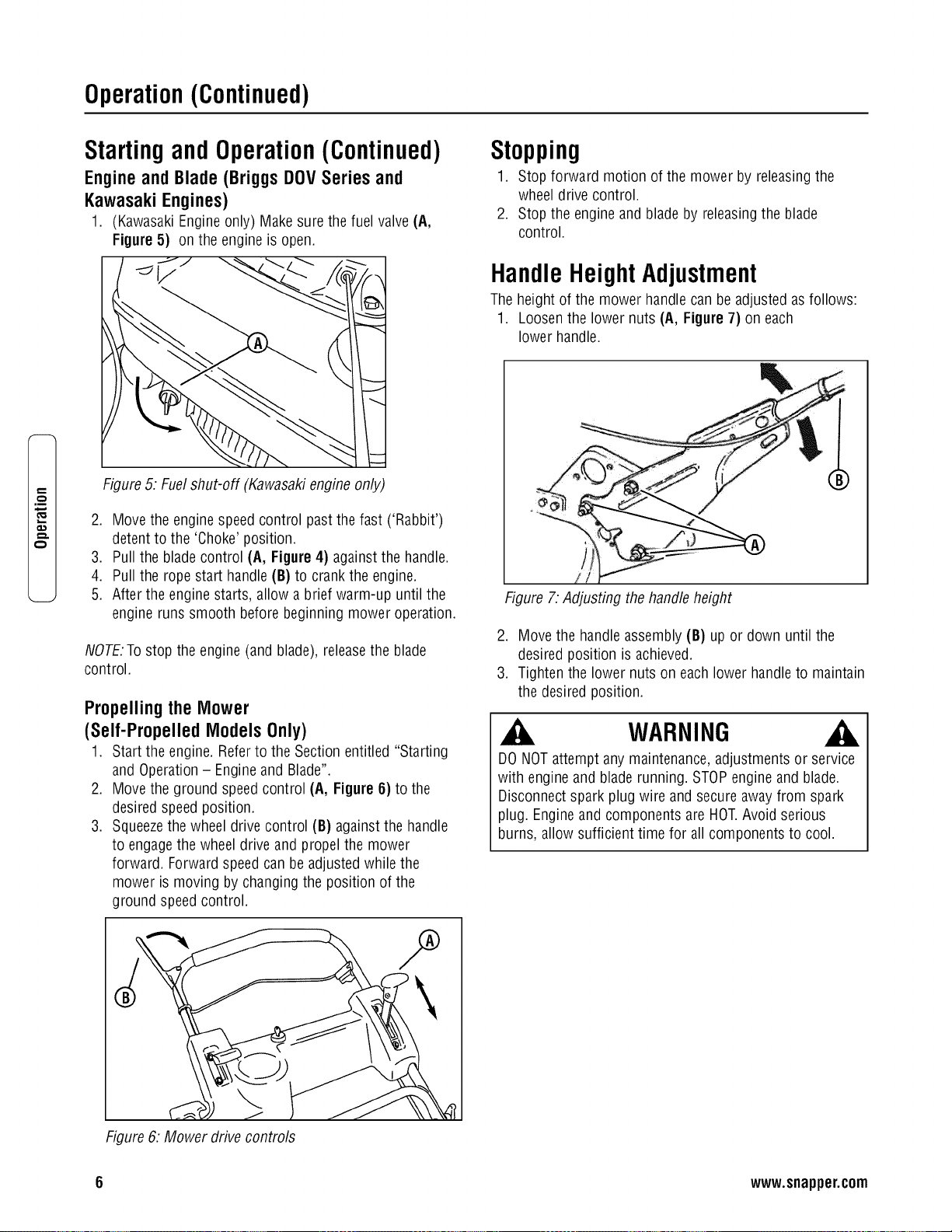
Operation(Continued)
t::
€:)
,m
o.1
Startingand Operation(Continued)
Engine and Blade (Briggs DOV Series and
Kawasaki Engines)
1. (Kawasaki Engine only) Make sure the fuel valve(A,
Figure 5) on the engine is open.
Figure 5: Fuel shut-off (Kawasaki engine only)
2. Move the engine speed control past the fast ('Rabbit')
detent to the 'Choke' position.
3. Pull the blade control (A, Figure 4) against the handle.
4. Pull the rope start handle (B) to crank the engine.
5. After the engine starts, allow a brief warm-up until the
engine runs smooth before beginning mower operation.
NOTE.To stop the engine (and blade), releasethe blade
control.
Propelling the Mower
(Self-PropelledModels Only)
1. Start the engine. Refer to the Section entitled "Starting
and Operation - Engineand Blade".
2. Move the ground speedcontrol (A, Figure 6) to the
desired speed position.
3. Squeezethe wheel drive control (B) againstthe handle
to engagethe wheel drive and propel the mower
forward. Forward speed can be adjusted while the
mower is moving by changing the position of the
ground speed control.
Stopping
1. Stop forward motion of the mower by releasingthe
wheel drive control.
2. Stop the engine and blade by releasingthe blade
control.
HandleHeightAdjustment
The height of the mower handle can be adjusted as follows:
1. Loosen the lower nuts (A, Figure 7) on each
lower handle.
Figure 7: Adjusting the handle height
2. Move the handleassembly (B) up or down until the
desired position is achieved.
3. Tighten the lower nuts on each lower handleto maintain
the desired position.
WARNING
DO NOT attempt any maintenance, adjustments or service
with engine and blade running. STOPengine and blade.
Disconnect spark plug wire and secure away from spark
plug. Engine and components are HOT.Avoid serious
burns, allow sufficient time for all components to cool.
Figure 6: Mower drive controls
6 www.snapper.com

Operation(Continued)
WARNING
DONOT attempt any maintenance,adjustments or service
with engine and blade running. STOPengine and blade.
Disconnect spark plug wire and secure away from spark
plug. Engine and components are HOT.Avoid serious
burns, allow sufficient time for all components to cool.
CuttingHeightAdjustment
1. Pull the height adjusting latch (A, Figure8) outward and
move to the desired cutting height.
Figure 8: Adjusting cutting height
2. Set all wheels at the same cutting height. The highest
cutting position is Notch 7 (Figure 9). The lowest
cutting position is Notch 1.
1.25 in 4.00 in
Figure 9: Cutting height settings (approximate)
RecyclingOperation
Note: For best recycling results, cut up to a maximum of 1/3
of grass blade length and recycle ONLYwhen grass is dry.
1. Set all wheels in the highest cutting position (Notch 7).
Referto the Section entitled "Cutting Height
Adjustment".
2. Move the engine speed control to the fast (Rabbit)
position.
3. Move the ground speed control to the slowest speed
setting.
4. Proceed mowing slowly. If the grass is very dense,
lower each rearwheel latch one notch lower than the
front wheel latches to improve recycling performance.
Note: The recycling cover should remain on the machineat
all times, unless alternatedischarge operations are desired,
such as side discharging or bagging.
Removingthe RecyclingCover
1. Removethe knob nuts (A, Figure 10) and internal/
externaltooth lock washers (B) securing the recycling
cover (C) to the mower deck.
2. Remove the cover.
Figure 10. Removing the recycling cover
m.
WARNING
Stop engine and mower blade by releasing the blade
control before adjusting cutting height.

Operation(Continued)
t_
,m
WARNING
DONOT attempt any maintenance,adjustments or service
with engine and blade running. STOPengine and blade.
Disconnect spark plug wire and secure away from spark
plug. Engine and components are HOT.Avoid serious
burns, allow sufficient time for all components to cool.
Installingthe DischargeDeflector
1. Remove the recycling cover. Refer to the Section entitled
"Recycling Operation".
2. Install the deflector (A, Figure 11) to the deck in place
of the recycling cover, making sure that:
• The front hole (B) on the outside front of the
deflector fits over the stud where the front of the
recycling cover was originally secured
• The slot (C) on top of the deflector slips underthe
restraining nut on top of the deck (under the right
front corner of the engine)
• The slot (D) on the inside rear of the deflector slips
onto the stud behind the rear of the discharge
opening, where the rear of the recycling cover was
originally secured.
3. Install the internal/externaltooth lock washers and knob
nuts onto the studs and tighten securely.
Installingthe GrassBagAdapter
(Optional Accessory on Some Models)
1. Removethe recycling cover. Refer to the Section entitled
"Recycling Operation".
2. Install the adapter (A, Figure 12) to the deck in place of
the recycling cover, making sure that:
• The front hole (B) on the outside front of the
adapter fits over the stud where the front of the
recycling cover was originally secured
• The slot (C) on top of the adapter slips under the
restraining nut on top of the deck (under the right
front corner of the engine)
• The slot (D) on the rear of the adapter slips onto
the stud behind the rear of the discharge opening,
where the rear of the recycling cover was
originally secured.
3. Install the internal/externaltooth lock washers and knob
nuts onto the studs and tighten securely.
4. Route the recoil rope around the outside of the rope
guide pulley (E).
Note: The recoil rope may needto be slackened. Referto the
section entitled "Handle Assembly".
Figure 11: Installing the discharge deflector
Figure 12. Installing the grass bag adapter
.
(Kawasaki engines only) Attach the grass bag adapter
standoff (A, Figure 13) between the rope guide pulley
and the engine recoil:
• Removethe right rear bolt (B) from the
engine recoil
• Removethe torx screw and nut securing the rope
guide pulley (C) to the bracket on the bagadapter
• Laythe standoff between the bolt holes in the
engine recoil and the bag adapter pulley bracket.
(Position the standoff so that the bent end (D) is
toward the engine recoil cover.)
8 www.snapper.com

Operation(Continued)
WARNING
DONOT attempt any maintenance,adjustments or service
with engine and blade running. STOPengine and blade.
Disconnect spark plug wire and secure away from spark
plug. Engine and components are HOT.Avoid serious
burns, allow sufficient time for all components to cool.
Installingthe GrassBagAdapter
(Continued)
• Flip the pulley over so that the bushing flange is
under the pulley. The bushing will act as a washer
betweenthe pulley and the standoff.
• Reassemblethe pulley to the bag adapter, and
install the supplied replacementbolt, fitted with the
thread sleeve, into the recoil cover. Tighten all
hardware securely.
Figure 13: Installing the adapter standoff
(Kawasakiengines only)
WARNING
DONOT operate without entire Grass Catcheror guard in
place. Grass Catcher components are subject to
deterioration during normal use. Inspect frequently and
replaceworn or damaged components immediately.
Installingthe RecyclingPlug
1. Install the recycling plug (A, Figure 14) if recycling is
desired after the bag adapter is installed. Install the
recycling plug completely and securely into the bag
adapter (B).
IMPORTANT.Install the grass bag as a safeguard.
2. Refer to the Section entitled "Recycling Operation".
Figure 14. Installing the recycfing plug
Installingthe GrassBag
(Door Type Bag)
1. Install the grass bag adapter.Refer to the Section
entitled "Installing the Grass BagAdapter".
2. Install the grass bag by sliding the connector (A, Figure
15) over the adapter flange.
3. Attach the grass bag hooks (B) over the middle handle
cross bar.
®
Figure 15. Installing the grass bag
WARNING
GrassCatcher bags used on SNAPPERproducts are made
of woven fabric, and are subject to deterioration and wear
during normal usage. Check condition of bag before each
use. Immediately replace worn or damaged catcher bags
with only bags recommended by SNAPPER. The grass
catcher is optional equipment on some models.
m.

Maintenance
p,,
q-.
.m
_E
Maintenance-Introduction
To retain the quality of the mower, use genuine SNAPPER
replacement parts only. Contact a local SNAPPERdealer for
parts and service assistance.For the correct part or
information for a particular mower, always mention the
model and serial number.
WARNING
DONOT attempt any maintenance,adjustments or service
with engine and blade running. STOPengine and blade.
Disconnect spark plug wire and secure away from spark
plug. Engine and components are HOT.Avoid serious
burns, allow sufficient time for all components to cool.
Wear heavy leather gloves when handling or working
around cutting blades. Bladesare extremely sharp and can
causesevere injury.
Service- After First5 Hours
Change Engine Oil
1. Refer to the EngineManual for proper oil specifications,
procedures and proper service intervals.
2. For the simplest/cleanest oil change, simply turn the
mower on its side to drain the oil, as shown. Drain the
oil through the dipstick tube (A, Figure 16) into a
container. Allow sufficient time for all the oil to drain.
Important: Drain the fuel tank before tipping the machine.
DO NOT tip the machinewith the carburetor or spark plug
down. Oil from the crankcasewill saturate the air filter and
causethe engine to be hard to start or not start at all. If
contamination does occur, the air filter will haveto be
replaced.
CheckGreaseLevel in Transmission
1. Removethe transmission fill plug (A, Figure 17). Roll
the machine forward or backward while looking down
into the plug hole.
2. If liquid grease is not visible on the input gear (the small
gear below the plug hole), add an amount, to cover the
gear, of Snapper "00" grease.
Figure 17. Removing the transmission fill plug
Note: Snapper "00" grease (Part No. 7029443) is available at
your Snapper dealer.
Note: Do not spill grease or oil onto the surface of the drive
disc (A, Figure 18).
%
Figure 16: Draining the engine oil
3. Dispose of drain oil properly.
4. Fill the enginewith oil as specified in the Engine Manual.
Do not overfill.
Figure 18: Location of the drive disc
3. Reinstall the transmission plug.
4. Checkthe grease level after each 25 hours of operation.
Important:Drain the fuel tank before tipping the mower. DO
NOTtip the machine with the carburetor or spark plug down.
Oil from the crankcase will saturate the air filter and cause
the engine to be hard to start or not start at all. If
contamination does occur, the air filter will haveto be
replaced.
10 www.snapper.com
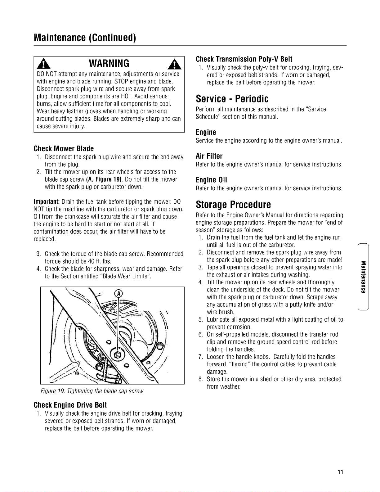
Maintenance(Continued)
WARNING
DONOT attempt any maintenance,adjustments or service
with engine and blade running. STOPengine and blade.
Disconnect spark plug wire and secure away from spark
plug. Engine and components are HOT.Avoid serious
burns, allow sufficient time for all components to cool.
Wear heavy leather gloves when handling or working
around cutting blades. Bladesare extremely sharp and can
causesevere injury.
Check Mower Blade
1. Disconnect the spark plug wire and securethe end away
from the plug.
2. Tilt the mower up on its rearwheels for accessto the
blade cap screw (A, Figure19). Do not tilt the mower
with the spark plug or carburetor down.
Important:Drain the fuel tank before tipping the mower. DO
NOTtip the machine with the carburetor or spark plug down.
Oil from the crankcasewill saturate the air filter and cause
the engineto be hard to start or not start at all. If
contamination does occur, the air filter will haveto be
replaced.
3. Checkthe torque of the bladecap screw. Recommended
torque should be 40 ft. Ibs.
4. Checkthe bladefor sharpness, wear and damage. Refer
to the Section entitled "BladeWear Limits".
Figure 19. Tightening the blade cap screw
Check Engine Drive Belt
1. Visually check the engine drive belt for cracking, fraying,
severedor exposed belt strands. If worn or damaged,
replace the belt before operating the mower.
Check Transmission Poly-V Belt
1. Visually check the poly-v belt for cracking, fraying, sev-
ered or exposed belt strands. If worn or damaged,
replacethe belt before operating the mower.
Service- Periodic
Perform all maintenanceas described in the "Service
Schedule" section of this manual.
Engine
Service the engine according to the engine owner's manual.
Air Filter
Referto the engine owner's manual for service instructions.
EngineOil
Referto the engine owner's manual for service instructions.
StorageProcedure
Referto the Engine Owner's Manual for directions regarding
engine storage preparations. Preparethe mower for "end of
season" storage as follows:
1. Drain the fuel from the fuel tank and let the engine run
until all fuel is out of the carburetor.
2. Disconnect and remove the spark plug wire awayfrom
the spark plug before any other preparations are made!
3. Tapeall openings closed to preventspraying water into
the exhaust or air intakes during washing.
4. Tilt the mower up on its rear wheels and thoroughly
clean the underside of the deck. Do not tilt the mower
with the spark plug or carburetor down. Scrapeaway
any accumulation of grass with a putty knife and/or
wire brush.
5. Lubricate all exposed metal with a light coating of oil to
prevent corrosion.
6. On self-propelled models, disconnect the transfer rod
clip and remove the ground speed control rod before
folding the handles.
7. Loosen the handle knobs. Carefully fold the handles
forward, "flexing" the control cables to prevent cable
damage.
8. Store the mower in a shed or other dry area, protected
from weather.
m.
€'D
11

Maintenance(Continued)
,m
_E
WARNING
DONOT attempt any maintenance,adjustments or service
with engine and blade running. STOPengine and blade.
Disconnect spark plug wire and secure away from spark
plug. Engine and components are HOT.Avoid serious
burns, allow sufficient time for all components to cool.
Wear heavy leather gloves when handling or working
around cutting blades. Bladesare extremely sharp and can
causesevere injury.
MowerBladeReplacement
Standard Blade Wear Limit
1. Inspect the blade(Figure 20) frequently for signs of
excessivewear or damage:
(A) New blade
(B) Wear limit (notch starts)
(C) Dangerous condition! Do not use on the mower!
Replacewith a new blade.
Figure 20: Standard blade wear limits
Ninja Blade Wear Limit
1. Inspect the blade(Figure 21) frequently for signs of
excessivewear or damage:
(A) New blade
(B) Wear limit (cracks or notches begin to appearon
tip)
(C) Dangerous condition! Do not use on the mower!
Replacewith a new blade.
WARNING
DONOT use a cutting bladethat shows signs of excessive
wear or damage.Refer to the Section entitled "MOWER
BLADEREPLACEMENT"for proper blade inspection and
service procedures.
Figure 21: Ninja blade wear fimits
BladeSharpening
1. Disconnect the spark plug wire and secure the end away
from the plug.
2. Tilt the mower up on its rear wheels. Do not tilt the
mower with the spark plug or carburetor down.
Important:Drain the fuel tank before tipping the mower. DO
NOTtip the machine with the carburetor or spark plug down.
Oil from the crankcase will saturate the air filter and cause
the engineto be hard to start or not start at all. If
contamination does occur, the air filter will haveto be
replaced.
3. Remove the blade (B, Figure22).
Makesure that
bladehub is seatedI
[betweenfanges J
i
Figure 22: Removing the mower blade
12 www.snapper.com

Maintenance(Continued)
WARNING
DO NOTattempt any maintenance, adjustments or service
with engine and blade running. STOPengineand blade.
Disconnect spark plug wire and secure awayfrom spark
plug. Engineand components are HOT.Avoid serious
burns, allow sufficient time for all components to cool.
BladeSharpening(Continued)
4. Sharpen the bladeon a grinding wheel at an angle of 22
to 28 degrees (B, Figure 23). DO NOTsharpen the blade
beyond the original cutting edge(A).
Do not sharpen
beyond original
cutting edge
Endview of
bladeassembly
Figure 23: Sharpening the mower blade
5. Check blade for balance.If necessary,correct balance by
grinding heavyend of blade.
6. Reinstall blade (B, Figure 22}. Note the correct
assembly order:
(A) Blade hub
(B) Blade
(C) Bladeflange (facing up)
(D) Conewasher (concave side up)
(E) Capscrew
7. Checktorque of blade retaining cap screw.
Recommendedtorque should be 40 ft. Ibs.
Wheel DriveControlAdjustment
(Self-PropelledModelsOnly)
1. The wheel drive control is properly adjusted when there
is 1/16" to 1/8" clearance (G, Figure24) betweenthe
inside of the spring hook (E) and the inside of the clutch
cable eye (C) with the wheel drive control released.
Figure 24: Wheeldrive control adjustment
2. To adjust, unhook the upper spring (D) from the cable
eye and rotate the spring in the direction required to
extend or shorten the spring length.
3. Rehook the upper spring to the cable eye and check
clearance. Repeatthe procedure if required.
Note. Thevinyl spring cover(B) should be kept over the
spring at aft times except for adjustments.
.
If the wheel drive control fails to return quickly to the
"OFF" position when released,check for binding at the
cable holdings located on the side of the right handle.
The upper clip should be located 2" below the upper
knob; the lower clip should be 4" above the lower knob.
The cable should slide freely with the clips installed at
these locations.
m.
€'D
13

Maintenance(Continued)
e,,,
t_
.m
_E
WARNING
DO NOTattempt any maintenance, adjustments or service
with engine and blade running. STOPengineand blade.
Disconnect spark plug wire and secure awayfrom spark
plug. Engineand components are HOT.Avoid serious
burns, allow sufficient time for all components to cool.
Drivenand DriveDiscService
If the mower does not propel itself properly, check for the
following problems:
Figure 25. Wheel drive components
1. Greaseon the drive disc (A, Figure 25) causing
slippage.
2. Broken or disconnected drive spring (B).
3. Driven disc (C) is out of adjustment.
4. Driven disc rubber is worn - does not contact drive disc
properly.
5. Worn Poly-V belt (D) or engine drive belt (E).
If any of the above (1 thru 5) are causing problems, service
as follows:
Cleaning Drive Disc & Driven Disc
If oil or greaseon the drive disc or driven disc is causing
slippage, clean the discs as follows:
1. Wipe away any oil or grease with a clean cloth.
2. Use either an approved grease solvent or hot, soapy
water to clean drive disc or driven disc.
3. Rinse components with clean water.
4. Dry components with a clean cloth.
DriveSpringRepair/Replacement
If the drive spring (A, Figure 26) is loose, reconnect. If the
spring is broken, replacewith a new spring.
Note: Usea pair of needlenose pliers to install the drive
spring.
IMPORTANT:If the drive system continues slipping, refer to
the Troubleshooting section.
Figure 26: Replacingthe drive spring
Driven Disc Adjustment
If the drive disc and driven disc are clean and the mower
drive is still slipping, adjust the driven disc as follows:
1. Move the ground speed control (A, Figure 27) into the
'fast' position.
Figure 27: Theground speed control
14 www.snapper.com
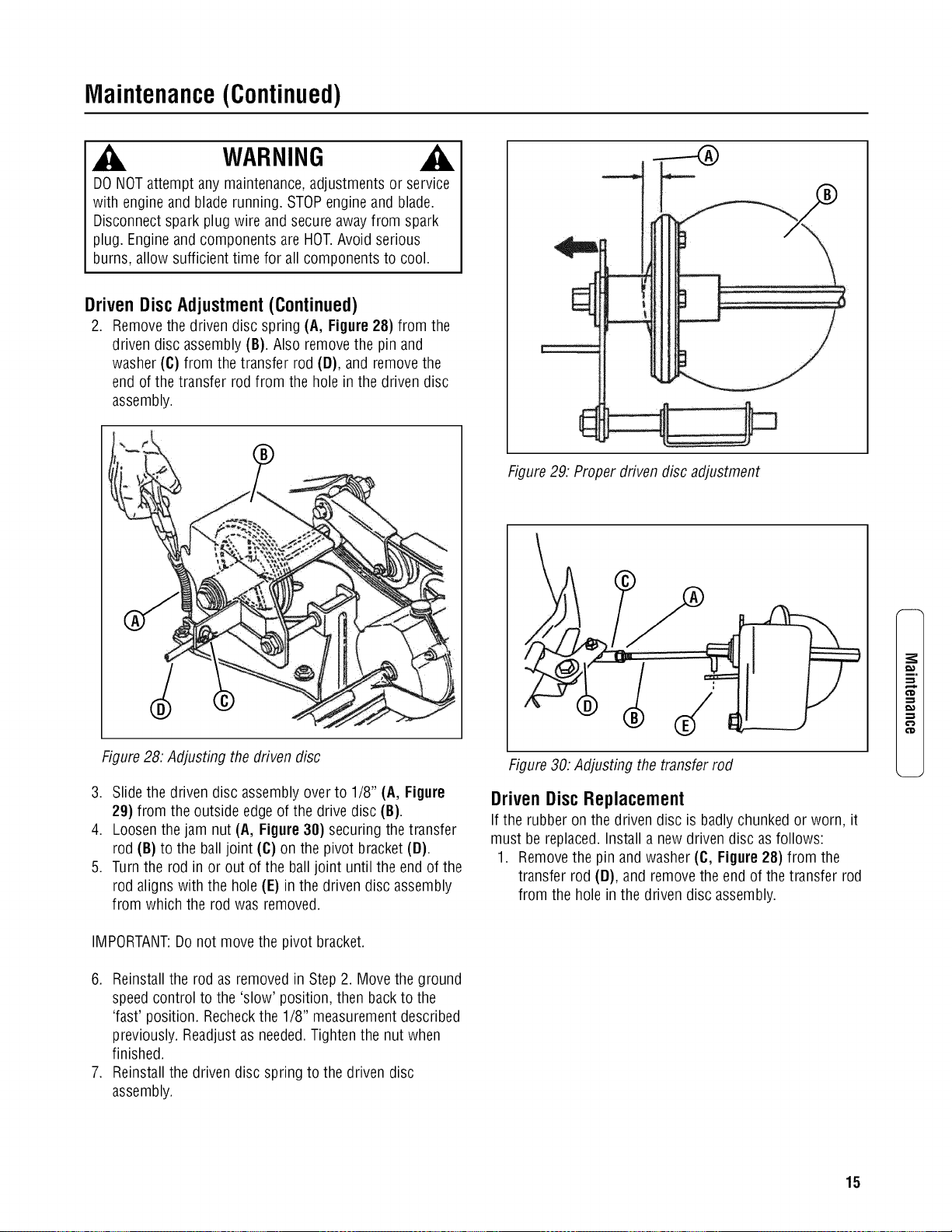
Maintenance(Continued)
WARNING
DO NOTattempt any maintenance, adjustments or service
with engine and blade running. STOPengineand blade.
Disconnect spark plug wire and secure awayfrom spark
plug. Engineand components are HOT.Avoid serious
burns, allow sufficient time for all components to cool.
Driven Disc Adjustment (Continued)
2. Remove the driven disc spring (A, Figure 28) from the
driven disc assembly (B). Also remove the pin and
washer (C) from the transfer rod (D), and removethe
end of the transfer rod from the hole in the driven disc
assembly.
Figure 28: Adjusting the driven disc
3. Slide the driven disc assembly over to 1/8" (A, Figure
29) from the outside edge of the drive disc (B).
4. Loosen the jam nut (A, Figure 38) securing the transfer
rod (B) to the ball joint (C) on the pivot bracket (D).
5. Turn the rod in or out of the ball joint until the end of the
rod aligns with the hole (E) in the driven disc assembly
from which the rod was removed.
IMPORTANT:Do not move the pivot bracket.
6. Reinstall the rod as removed in Step 2. Move the ground
speed control to the 'slow' position, then back to the
'fast' position. Recheckthe 1/8" measurement described
previously. Readjustas needed.Tighten the nut when
finished.
7. Reinstall the driven disc spring to the driven disc
assembly.
Figure 29: Proper driven disc adjustment
Figure 30: Adjusting the transfer rod
Driven Disc Replacement
If the rubber on the driven disc is badly chunked or worn, it
must be replaced. Install a new driven disc as follows:
1. Removethe pin and washer (C, Figure 28) from the
transfer rod (D), and remove the end of the transfer rod
from the hole in the driven disc assembly.
m.
15

Maintenance(Continued)
e,,,
t_
.m
_E
WARNING
DO NOTattempt any maintenance, adjustments or service
with engine and blade running. STOPengineand blade.
Disconnect spark plug wire and secure awayfrom spark
plug. Engineand components are HOT.Avoid serious
burns, allow sufficient time for all components to cool.
Driven Disc Replacement (Continued)
2. Using needle nose pliers, unhook the drive spring (A,
Figure 31) and slide the driven disc assembly off the
hex shaft.
3. Remove the two snap rings (A, Figure 32) which secure
the rubber driven disc (B) to the driven disc assembly.
4. Install a new rubber driven disc onto the driven disc
assembly, and secure with the retaining rings.
5. Reversethe above proceduresfor reassembly and
installation of the driven disc assembly.
Driven Disc Bearing Replacement
IMPORTANT:The bearing on these machines is staked into
the thrust plate. The bearing will haveto be driven out with a
mallet and a large punch. A new bearing with four retaining
screws will haveto be purchased to replace existing bearing.
If the driven disc bearing requires replacement, replace the
bearing as follows:
1. Removethe driven disc assembly. Refer to the Section
entitled "Driven Disc Replacement".
2. Remove both snap rings (A, Figure 32) that secure the
rubber driven disc (B) to the thrust plate.
3. Slide the rubber driven disc hub out of the bearing.
4. Drive out the existing bearing (C).
5. Install a new bearing and secure to the thrust plate with
four retaining screws. Tighten the screws securely.
6. Reassemblethe components in reverse order.
NOTE:Be sure to replace the shim washer (D) when
reassembfingthe driven disc assembly.
Figure 31. Removing the driven disc assembly
Figure 32: Replacing the driven disc
16 www.snapper.com

Maintenance(Continued)
WARNING
DO NOTattempt any maintenance, adjustments or service
with engine and blade running. STOPengineand blade.
Disconnect spark plug wire and secure awayfrom spark
plug. Engineand components are HOT.Avoid serious
burns, allow sufficient time for all components to cool.
Replacing the Bearing On the Pulley End Of the
Hex Shaft
To replace the bearing on the pulley end of the hex shaft,
proceed as follows:
1. Hold the hex shaft with an adjustable wrench held next
to the pulley.
2. Remove the 3/8" hex lock nut (B, Figure33), located on
the outside of the right wheel bracket.
3. Remove the holder (A), O-ring (C) and bearing (D).
4. Install the new bearing.
5. Carefully install the new O-ring over the outside of the
new bearing.
6. Install the bearing holder, and secure with screws.
7. Install the 3/8" hex lock nut.
BeltService
On self-propelled mowers, the engine belt (A, Figure 34)
transmits power from the engine pulley (B) to the drive disc
(C). The drive disc powers the poly-v belt, which engages the
transmission that powers the rearwheels. Should these belts
become worn, they could cause slippage,which would
impair mower performance. The condition of the engine belt
and poly-v belt should be checked after every 25 hours of
mower operation.
Engine Drive Belt Replacement (Stretch Type
Belts)
1. Empty the fuel tank.
2. Note the belt routing (Figure 34). There is no idler
pulley on these models to disconnect.
f ,.. o "_ \//>_ "l,
\% \/ /I//
Figure 34. Engine drive belt routing
i.
€'D
€'D
Figure 33. Replacingthe hex shaft bearing
17

Maintenance(Continued)
e,,,
t_
.m
_E
WARNING
DO NOTattempt any maintenance, adjustments or service
with engine and blade running. STOPengineand blade.
Disconnect spark plug wire and secure awayfrom spark
plug. Engineand components are HOT.Avoid serious
burns, allow sufficient time for all components to cool.
EngineDrive Belt Replacement(StretchType
Belts- Continued)
IMPORTANT:Drain the fuel tank before tipping the mower.
DO NOT tip the machinewith the carburetor or spark plug
down. Oil from the crankcase will saturate the air filter and
causethe engine to be hard to start or not start at all. If
contamination does occur, the air filter will haveto be
replaced.
3. Remove the driven disc. Referto the Section entitled
"Driven Disc Replacement"for driven disc removal
procedure.
4. Drain the fuel tank before tipping the mower. Do not tilt
the mower with the spark plug or carburetor down. Tilt
the mower up on its rear wheels and removethe blade
and bladehub. Assistance from another person may be
necessaryto hold the mower in the tilted position.
5. Hold the slotted end of the drive disc bolt (B, Figure 35)
with a screwdriver and remove the nut (G) and internal
tooth lock washer (F).
6. Remove the belt cover, located under the deck.
7. Lift the drive disc (A) up and remove the worn belt.
8. Loop one end of the new belt over the engine pulley and
insert the other end through the slot in the deck.
9. Loop the belt around the pulley on the bottom of the
drive disc.
10.Reinstall the drive disc and retaining hardware.
IMPORTANT:1) The square shoulder of the drive disc bolt
must fit into the square hole of the bushing. 2) The square
end of bushing must fit into the bracket slot.
11.Reinstall the belt cover and tighten the bolts securely.
12.Reinstall the blade hub and cutter blade. Recommended
torque for the blade cap screw is 40 ft. Ibs.
------4b
)
Figure 35. Removing the drive disc
Transmission Poly-V Belt Replacement
1. Remove the driven disc. Referto the Section entitled
"Replacing Driven Disc Rubber Ring".
2. Note the routing of the old belt around the three pulleys
before removing it.
3. Place the new Poly-V Belt (A, Figure 36) over the end of
the hex shaft (B) and onto the drive pulley (C).
4. Work the belt onto the top of the idler pulley (D).
5. Twist the belt sideways and pull it upward betweenthe
differential bracket (E) and driven pulley (F) and then
down into the pulley groove. Make sure the Poly-V Belt
is above the belt guide (G).
J
Figure 36. Poly-v belt routing
18 www.snapper.com

Maintenance(Continued)
BatteryService
New BatteryPreparation
1. Remove the battery from the carton.
2. Placethe battery in a well ventilated area on a level non-
concrete surface.
3. Remove the battery cell caps. Fill the cells as required
with electrolyte (supplied with battery) to the proper
level. Filling the battery with electrolyte will bring the
battery to 80% charged state.
4. With the cell caps removed, connect the battery charger
to the battery terminals; REDto positive (+) and BLACK
to negative (-) terminal.
IMPORTANT:Neverplace anything in the battery other than
the specified electrolyte.
5. Slow charge the battery at 1 amp for 2 hours to bring
the battery to full charge.
6. After charging, check the level of electrolyte and add as
neededto bring to the proper fluid level.
7. Reinstall the cell caps.
8. Install the battery into the power unit.
9. Connect the positive (+) cable (red) first, from the wiring
harness to the positive terminal (+) on the battery using
the bolt and nut provided in the hardware bag. Connect
the negative (-) cable (black) last, to the negativetermi-
nal (-) on the battery using the bolt and nut. Apply a
small amount of grease over the terminals to prevent
corrosion.
WARNING
DONOToverfill batterywithelectrolyte.Shieldthe positive
terminalwithterminalcoverlocatedonbatteryharness.This
preventsmetalfrom touchingthe positiveterminal,which could
causesparks.Theelectrolyte(acid)producesa highlyexplosive
gas.Keepall sparks,flameandfire awayfrom areawhen
chargingbatteryor whenhandlingelectrolyteor battery.
Electrolyte(acid)is a highlycorrosiveliquid.Weareyeprotection.
Washaffectedareasimmediatelyafterhavingeyeor skincontact
with electrolyte(acid).Batteryacid is corrosive.Rinseemptyacid
containerswithwaterandmutilatebeforediscarding.If acidis
spilledon battery,bench,or clothing,etc.,Flushwith clearwater
andneutralizewith bakingsoda.Neverattemptto chargebattery
while installedonthe walk behind.Neveruse"BOOST"chargers
onthe battery.
BatteryService
1. Removethe battery.
2. Place the battery in a well ventilated areaon a level sur-
face.
3. Using distilled water, refill the cells as required to cover
the cell plates.
4. With the cell caps removed, connect the battery charger
to the battery terminals. Redto positive (+) terminal
and black to negative (-) terminal.
5. Slow charge the battery at 1 amp for 10 hours.
6. If the battery will not accept a charge or is partially
charged after 10 hours of charging at 1 amp, replace
with a new battery.
BatteryStorage
If the Walk Behindis to be stored out of season on its rear
bumper, it is recommendedthe battery be removed, charged
and stored.
1. Removethe battery.
2. Perform battery service.
3. Bring the battery to full charge, if required.
4. Store the battery in an area awayfrom the Walk Behind
on a wood surface. DO NOT STOREBATTERYON A
CONCRETESURFACE.
Battery Testing
There are two types of battery tests: Unloaded and Loaded.
The unloaded test is the procedure that will be discussed. It's
the simplest and most commonly used. An unloadedtest is
made on a battery without discharging current. To perform
unloaded testing, check charge condition using either a
hydrometer or voltmeter.
.
.
Using a voltmeter, voltage readings appear instantly to
show the state of charge. Rememberto hook the posi-
tive leadto the battery's positive terminal, and the nega-
tive leadto the negative terminal.
A hydrometer measuresthe specific gravity of each cell.
The specific gravity tells the degree of charge; generally,
a specific gravity of about 1.265 to 1.280 indicates full
charge. A readingof 1.230 to 1.260 indicates the battery
should be charged. The chart below shows the charge
level as measured by syringe float hydrometer, digital
voltmeter and five ball hydrometer.
Methodsof CheckingBattery Condition
State of Charge SyringeHydrometer Digital Voltmeter Five Ball Hydrometer
100% Chargedw/Sulfate Stop 1.280 12.80v FiveBalls Floating
100% Charged 1.265 12.60v Four Balls Floating
75% Charged 1.210 12.40v Three Balls Floating
50% Charged 1.160 12.10v Two Balls Floating
25% Charged 1.120 11.90v One Ball Floating
0% Charged Lessthan 1.100 Lessthan 11.80v Zero Balls Floating
m,
¢D
€'D
19

,m
ServiceSchedule
ITEM
Engine Oil
Air Pre-Cleaner
Air Cleaner
Spark Plug
EngineCooling
System
Drive Belts
Mower Blade
Mower Deck
Transmission
Grease
Drive Disc
SERVICE
PERFORMED
Check Oil Level
Initial Oil Change
Periodic Oil Change
CleanSponge Element
Cleanor Replace
Replace
CleanShroud & Fins
Check tor Wear and
Tension
Check for wear, Damage
& Replacement
Clean Debris
Accumulation
CheckGrease Level
Periodic GreaseCheck
Check for Wear Damage
and Replacement
REF.
Page5
Page10
Page11
EngineManual
EngineManual
EngineManual
EngineManual
EACH
USE
5
HRS
X
Page11, 17
Page12 X
Page5 X
Page10
Page10
Page13-16
* Changeoil every 25 hours when operating under heavy load or high temperatures.
** Cleanmore often under dusty conditions or when air debris is present.
25
HRS
X_
X**
X**
5O
HRS
lOO
HRS
X
X**
Maintenance/ReplacementParts
EngineSpeed Control (Briggs Engines)
EngineSpeed Control (KawasakiEngines)
BladeControl Cable (Briggs Engines)
BladeControl Cable (KawasakiEngines)
Clutch Pull Cable
Cutter Blade(Air Lift Compatible)
Cutter Blade(Mulching)
Cutter Blade(Not Air Lift Compatible)
Cutter Blade(Ninja - Quad Edge)
Wheel Drive Pulley to Transmission Pulley Belt
Engineto Drive Disc Belt
Cantilever Drive Tire Assembly
Rubber Drive Tire
Parts Manual for 21" Steel Deck Walk Behind Mower Series 19 - Recycling ('R') Series
Parts Manual for 21" Steel Deck Walk Behind Mower Series 19
EACH
SEASON
X
X
X
7074460
7074138
7034608
7074141
7034604
7019795
7017168
7026691
7026407
7012354
7046784
7073528
7041855
7006149
7006150
20 www.snapper.com

Troubleshooting
PROBLEM
Engine Will Not Start Using
Recoil Starter
Engine Will Not Start (Electri(
Start Models)
Engine Stalls or Stops After
Running
Engine Loses Power
Excessive Vibration
IVlowerWill Not IVloveLoss
Of Traction (Self-Propelled
Models)
Cutting Grass Improperly
Poor Grass Discharge
Oil Leaking
PROBABLECAUSE
1. Fuel tank empty. 1.
2. Engine needs choking or priming. 2.
3. Spark plug wire disconnected. 3.
4. Kawasaki Engines Only - Fuel shut-oft in the 'Off' 4.
)osition.
1. Fuel tank empty. 1.
2. Engine needs choking or priming. 2.
3. Spark plug wire disconnected. 3.
4. Wiring harness disconnected. 4.
5. Battery dead. 5.
6. Kawasaki Engines Only - Fuel shut-off in the 'Off' 6.
)osition.
1. Blade control is released or is not being held
securely against handle.
2. Fuel tank empty.
3. Engine air pre-cleaner and or air cleanerdirty.
4. Spark plug detective or gap set improperly.
CORRECTIVEACTION
Fill tuel tank with tresh fuel.
Choke/Prime. Check Engine IVlanualfor Instructions.
Place spark plug wire onto spark plug.
lurn Fuel shut-oft to 'On' position.
Fill tuel tank with tresh tuel.
Choke/Prime. Check Engine Manual for Instructions.
Place spark plug wire onto spark plug.
Connect wiring harness.
Charge or replace battery.
lurn Fuel shut-off to 'On' position.
1. Blade control should be held securely against handle
at all times during operation of mower.
2. Fill with fuel to proper level.
3. Clean tree of all debris.
4. Service spark plug.
5. Water, debris or stale fuel in fuel system. 5.
6. Kawasaki Engines Only - Fuel shut-oft in the 'Ott' 6.
)osition.
1. Engine air pre-cleaner or air cleaner dirty. 1.
2. Spark plug faulty. 2.
3. Water, debris or stale fuel in fuel system. 3.
1. Damaged, out of balance or bent mower blade. 1.
2. Loose blade components. 2.
3. Loose or missing air Iitt (it equipped). 3.
4. Lumpy or trayed belt. 4.
1. Build-up of debris on or around wheel drive 1.
components.
2. Driven disc slipping.
3. Drive belt requires replacement.
4. Damaged transmission.
1. Cutting height too low or high.
2. Engine speed too slow.
3. Forward ground speed too fast.
4. lerraced cut, side to side.
5. Excessive deck pitch, front to rear.
6. Cutting blade dull or damaged.
1. Engine speed too fast. 1.
2. Forward speed too tast. 2.
3. Grass is wet. 3.
4. Excessively worn or damaged blade. 4.
5. Build up of grass clippings and debris under deck. 5.
6. Improper blade installed on deck. 6.
7. Blade installed improperly on deck. 7.
1. Leaking engine case. 1.
2.
Drain and clean fuel system.
lurn Fuel shut-oft to 'On' position.
Clean or replace tilters.
Service spark plug.
Drain and clean fuel system.
Service mower blade.
Service and tighten loose parts.
Replaceair lifts, lighten to proper torque.
Replace belt.
Clean debris.
2. Clean or replace driven disc.
3. Replace drive belt.
4. Contact authorized SNAPPERdealer.
1. Adjust cutting height.
2. Move engine speed control to 'Fast' position.
3. Move ground speed control to a slower speed.
4. Adjust height of cut with height adjust levers.
5. Adjust height of cut with height adjust levers.
6. Sharpen cutting edges or replace blade.
Move engine speed control to 'Fast' position.
IVloveground speed control to a slower speed.
IVlowwhen grass is dry.
Service mower blade.
Clean deck.
Install proper SNAPPEHblade.
Install blade properly.
Contact authorized SNAPPERdealer.
Check and tighten drain plug.
3. IVlakesure dip stick or oil tiller cap is securely in
)lace.
=3"
m.
21
t_
,m
2 YEAR LIMITED WARRANTY
For two (2) years from purchase date for the original purchaser's residential, non-commercial use, SNAPPER,through any
authorizedSNAPPERdealerwill replace,free of charge (except for taxes where applicable), any part or parts found upon
_xamination by the factory at McDonough, Georgia,to be defective in material or workmanship or both.
For ninety (90) days from purchasedate for the original purchaser's commercial, rental, or other non-residential use, SNAP-
PER,through any authorized SNAPPERdealer will replace,free of charge,any part or parts found upon examination by the
[actory at McDonough, Georgia,to be defective in material or workmanship or both.
&ll transportation costs incurred by the purchaser in submitting material to an authorized SNAPPERdealerfor replacement
underthis warranty must be paid by the purchaser.
This warranty does not apply to certain transmissions, to engines and their components, and batteries, as these items arewar-
ranted separately. This warranty does not apply to parts that havebeen damaged by accident, alteration, abuse, improper
lubrication, normal wear, or other causebeyond the control of SNAPPER.This warranty does not cover any machine or com-
ponent part that has been altered or modified changing safety, performance, or durability.
Batteries have a one (1) year warranty period with free replacement if required for one (1) year from the original purchase
date.SNAPPERwill not be responsible for any installation cost incurred. The battery warranty only covers original equipment
batteries and does not cover damageto the battery or machine caused by neglect or abuse, destruction by fire, explosion,
[reezing, overcharging, improper maintenance, or use of improper electrolyte.
There is no other express warranty.
DISCLAIMMEROFWARRANTY
Implied warranties, includingthoseof merchantabilityand fitness for a particular purpose, are limited to two (2) years
[rom purchasedate for the original purchaser'sresidential or other non-commercialuse, and ninety(90) daysfrom pur-
chase for the original purchaser'scommercial, rental or other non-residentialuse, and to the extent permittedby law, any
andall implied warranties are excluded. This is the exclusiveremedy. Liabilities for consequentialdamages, underany
andall warrantiesare excluded.
Somestates do not allow limitations on how long an implied warranty lasts, or do notallow the exclusionor limitation of
incidentalor consequentialdamages, so the abovelimitation or exclusionmay notapply to you.
Thiswarranty gives you specific legal rights, and you may also have other rights which vary from state to state.
WARNING:THE USEOF REPLACEMENTPARTSOTHERTHAN GENUINESNAPPERPARTSMAY IMPAIR THESAFETYOF
SNAPPERPRODUCTSAND WILL VOIDANY LIABILITYANDWARRANTYBYSNAPPERASSOCIATEDWITH THE USEOF
SUCHPARTS.
IMPORTANT:
Pleasefill out the attached SNAPPERProduct Registration Card immediately and mail to:
Snapper'sProductRegistrationCenter, P.O.Box1379, IVlcDonough,Georgia30253
22 www.snapper.com

04
4- SLOPE GUIDE
........ :..../.b" DE_D_... SIGHT AND HOLD THIS GUIDE LEVEL WITH A VERTICAL TREE,
I ".... -'..'.._S A CORNER OF A STRUCTURE, A POWER LINE POLE, OR A FENCE.
j ........................
...... .....................
!
I
I
Operate a walk-behind mower
across the face of slopes,
never up or down slopes.
10 DEGREES 15 DEGREES
Operate a riding mower
up or down slopes, never
across the face of slopes.
On a riding mower to determine if a slope is safe to mow: (1) disengage the blade(s), (2) put the unit in reverse, and (3) try to back straight up the
slope. If you can back up the slope, it is generally safe to mow. However, if you do not feel safe, or if you are not completely sure, use this guide
anddo not mow a slope that is greater than 15 degrees. If the riding mower is used with a pull-behind or rear mounted attachment,
do not operate the und on a slope that is greater than 10 degrees.
A 15 degree slope is a hill that increases in height at approximately 2.5 feet in 10 feet.
A 10 degree slope is a hill that increases in height at approximately 1.7 feet in 10 feet.
Use extreme care at all times, and avoid sudden turns or maneuvers. Follow other instructions in this manual for safety in mowing on
slopes. Operate a riding mower up or down slopes, never across the face of slopes. Operate a walk-behind mower across the face
of slopes, never up or down slopes. Use extra care when operating on or near slopes and obstructions.
................................. _U'T_E'R_fO'U§E'_GP__&_D'E.................................

Notes
24 www.snapper.com

Notes
25

21" STEELDECK
WALKMOWERS
SERIES19
Product Specifications
Deck Size
Height of Cut
Transmission Type (Self-Propelled Models)
Ground Speed (Self-Propelled Models)
Engine Power - Briggs Quantum / DOV
Engine Power- Briggs Intek
Engine Power- Kawasaki
Engine Displacement - Briggs DOV
Engine Displacement - Briggs Quantum / Intek
Engine Displacement - Kawasaki
Fuel Tank Capacity - Briggs (all)
Fuel Tank Capacity - Kawasaki
21 in
1,25- 4 in
Gear
1 -4 mph
6.50ft-lbs (gross)
8.75ft-lbs (gross)
6.0 hp (gross)
160cc
190cc
180cc
1.6 qt
2,1 qt
CommonServiceParts
Cutter Blade(Ninja - Quad)
Drive Belt (Engine)
Drive Belt (Transmission)
Parts Manual (Recycling)
Parts Manual
Part Number
7026407
7046784
7012354
7006149
7006150
EnginePower RatingInformation:The gross power rating for individual gas engine models is labeled in accordancewith
SAE(Society of Automotive Engineers) code J1940 (Small Engine Power & Torque Rating Procedure), and rating perform-
ance has been obtained and corrected in accordancewith SAEJ1995 (Revision 2002-05). Torque values are derived at 3060
RPM; horsepower values are derived at 3600 RPM. Actual gross engine power will be lower and is affected by, among other
things, ambient operating conditions and engine-to-engine variability. Given both the wide array of products on which engines
are placed and the variety of environmental issues applicable to operating the equipment, the gas enginewill not develop the
rated gross power when used in a given piece of power equipment (actual "on-site" or net power). This difference is due to a
variety of factors including, but not limited to, accessories (air cleaner,exhaust, charging, cooling, carburetor, fuel pump,
etc.), application limitations, ambient operating conditions (temperature, humidity, altitude), and engine-to-engine variability.
Due to manufacturing and capacity limitations, Briggs & Stratton may substitute an engine of higher rated power for this
Series engine.
SnapperProducts
535 Macon Street
McDonough, GA30253
26
1-000-935-2967
www.snapper.com

SafetyInstructions& Operator'sManual for
21" STEELDECK
WALKMOWERS
SERIES19
f
Models
RP2167519BD V (7800066)
RP2187519BV (7800172)
RP2187519BVE (7800173)
RP216019KWV (7800199)
2167519B
P2167519B
P2187519BV
P2187519BVE
P216019KWV
N2167519B
(7800217)
(7800218)
(7800176)
(7800178)
(7800193)
(7800133)
NP2167519B(7800134)
NP2187519BV (7800131)
J
NOTE:Specifications are correct at time of printing and are subjectto changewithout notice.
* Actualsustained engine power will likely he lower due to operating limitations and environmental factors. Please refer to 'Engine Power Rating Information' for
further details.
Manual No. 7101587 (I.R. 9/25/2007)
TP lO0-5289-1R-WB-N

ThankYou for purchasingthis quality-built Snapper product. We're pleasedthat you placedyour
confidence in the Snapper brand. When operatedand maintained according to the instructions in this
manual, your Snapper product will provide many years of dependableservice.
This manual containssafety information to makeyou awareof the hazardsand risks associatedwith the
machine and how to avoid them. This machine is designed and intended only for finish cutting of
established lawns and is not intendedfor any other purpose. It is important that you read and understand
these instructions thoroughly before attempting to start or operatethis equipment. Savethese
instructions for future reference.
PRODUCT REGISTRATION
IMPORTANT: KEEPTHIS INFORMATION FOR YOUR PERSONAL RECORDS
(Complete the following information on your Snapper purchase)
Date of Purchase
Retailer
Retailer's Phone Number
Equipment
Model Number
Serial Number
Engine
Model .Type. Trim
It is very importantthat youregisteryourpurchasewith Snapperto ensurewarrantycoverage.Please
mail yourproductregistrationcardto:
Snapper at P.O. Box 777, McDonough, Georgia 30253.
Or you may registeronline at www.snapper.com.
Youcan contactusat our website, or if you wouldlike to speakwith a CustomerService
Representative,call usat the SnapperCustomerRelationsCenterat 1-800-935-2967. Forfaster
serviceplease haveyourSerial Numberand Model Numberavailable.
SNAPPERis a trademarkof
Simplicity Manufacturing,Inc.
PortWashington,WI, USA.
Briggs& StrattonYard Power Products Group
Copyright© 2007, Briggs& StrattonCorporation
Milwaukee, WI, USA. All RightsReserved.
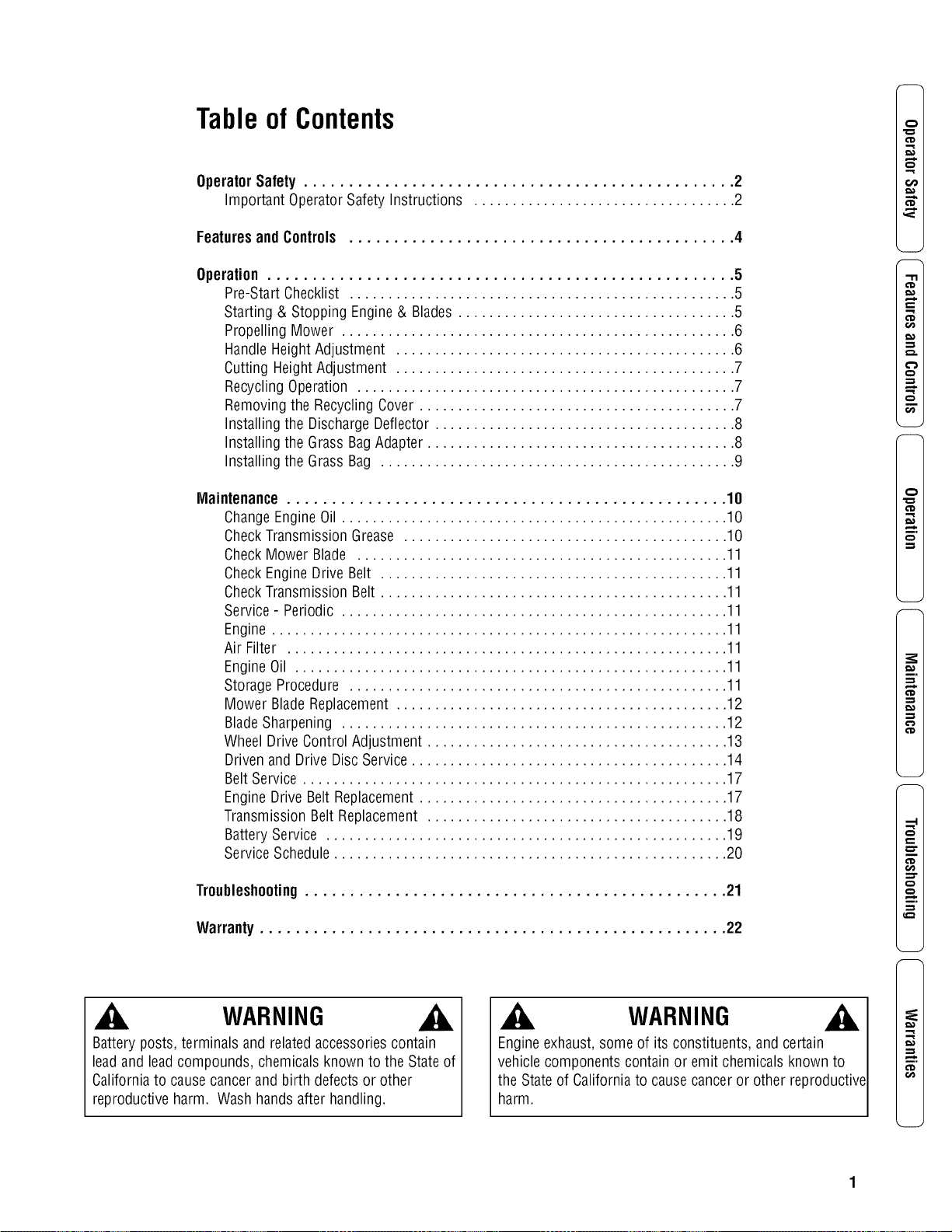
Tableof Contents
Operator Safety ................................................ 2
Important Operator Safety Instructions .................................. 2
Featuresand Controls ........................................... 4
Operation .................................................... 5
Pre-Start Checklist .................................................. 5
Starting & Stopping Engine & Blades .................................... 5
Propelling Mower ................................................... 6
Handle Height Adjustment ............................................ 6
Cutting Height Adjustment ............................................ 7
Recycling Operation ................................................. 7
Removing the Recycling Cover ......................................... 7
Installing the Discharge Deflector ....................................... 8
Installing the Grass Bag Adapter ........................................ 8
Installing the Grass Bag .............................................. 9
Maintenance ................................................. 10
ChangeEngine Oil .................................................. 10
CheckTransmission Grease .......................................... 10
Check Mower Blade ................................................ 11
Check Engine Drive Belt ............................................. 11
CheckTransmission Belt ............................................. 11
Service - Periodic .................................................. 11
Engine ........................................................... 11
Air Filter ......................................................... 11
Engine Oil ........................................................ 11
Storage Procedure ................................................. 11
Mower Blade Replacement ........................................... 12
BladeSharpening .................................................. 12
Wheel DriveControl Adjustment ....................................... 13
Driven and Drive Disc Service ......................................... 14
Belt Service ....................................................... 17
Engine Drive Belt Replacement ........................................ 17
Transmission Belt Replacement ....................................... 18
Battery Service .................................................... 19
Service Schedule ................................................... 20
Troubleshooting............................................... 21
Warranty .................................................... 22
WARNING
Battery posts, terminals and related accessoriescontain
lead and lead compounds, chemicals known to the State of
Californiato cause cancer and birth defects or other
reproductive harm. Wash hands after handling.
WARNING
Engineexhaust, some of its constituents, and certain
vehicle components contain or emit chemicals known to
the State of California to cause cancer or other reproductive
harm.
CD
"11
CD
CD
t_
,-1
t_
CD
mo
,-1
CD
,-1
,-1
CD
,..z.
--z
CD
t_

x,.,
,A
ImportantOperatorSafetyInstructions
WARNING:This powerful cutting machine is capable of amputating hands and feet and can throw objects
that can cause injury and damage! Failureto comply with the following SAFETYinstructions could result in
serious injury or death to the operator or other persons. The owner of the machine must understand these
instructions and must allow only persons who understand these instructions to operate machine. Each
person operating the machine must be of sound mind and body and must not be under the influence of any
substance,which might impair vision, dexterity or judgment. If you have any questions pertaining to your
machinewhich your dealer cannot answer to your satisfaction, call or write the Customer Service
Departmentat SNAPPER,IVIcDonough,Georgia 30253. Phone: (1-800-935-2967).
Protection for Children
Tragic accidents can occur if the operator is not alert to the
presenceof children. Children are often attracted to the
machine andthe mowing activity. Never assume that
children will remain where you last saw them.
1. KEEPchildren out of the mowing area and under the
watchful care of a responsible adult other than the operator.
2. DO NOT allow children in yard when machine is operated
andturn machine OFFif anyone enters the area.
3. DO NOT allow pre-teenagechildren to operate machine.
4. ALLOW only responsible adults & teenagerswith mature
judgment under close adult supervision to operate machine.
5. DO NOT pull mower backwards unless absolutely
necessary.LOOKand SEEbehind and down for children,
pets and hazards before and while backing.
6. USEEXTRACAREwhen approaching blind corners,
shrubs, trees, or other objects that may obscure vision.
SlopeOperation
1. Slopes are a major factor relatedto slip and fall acci-
dents, which can result in severe injury. All slopes require
extra caution. If you feel uneasyon a slope, DO NOT mow
it.
2. Mow across slopes, never up-and-down. Exercise
extreme CAUTIONwhen changing directions on slopes. DO
NOTmow steep slopes or other areas where stability or
traction is in doubt. Referto the Slope Guide at the end of
this manual.
3. Useextra care with grass catchers or other attachments;
these affect the handling and the stability of the machine.
Preparation
1. Read,understand, and follow instructions and warnings
in this manual and on the mower, engine and attachments.
Know the controls and the proper use of the mower before
starting.
2. Only mature, responsible persons shall operate the
machine and only after proper instruction.
3. Data indicates that operators age 60 and above, are
involved in a large percentageof mower-related injuries.
Theseoperators should evaluatetheir ability to operate the
mower safely enough to protect themselves and others
from serious injury.
Preparation
(ContinuedFrom Previous Column)
4. Handle fuel with extra care. Fuels are flammable and
vapors are explosive. Useonly an approved fuel container.
DO NOT remove fuel cap or addfuel with engine running.
Add fuel outdoors only with engine stopped and cool. Clean
spilled fuel and oil from machine. DO NOTsmoke.
5. Checkthe areato be mowed and remove all objects such
as toys, wire, rocks, limbs and other objects that could
cause injury if thrown by blade or interfere with mowing.
Also note the location of holes, stumps, and other possible
hazards.
6. Keep people and pets out of the mowing area.
Immediately,STOP Blade,Stop engine and Stop mower if
anyone entersthe area.
7. Checkshields, deflectors, switches, blade controls and
other safety devices frequently for proper operation and
location.
8. Make sure all safety decals are clearly legible. Replace if
damaged.
9. Protect yourself when mowing and wear safety glasses, a
dust mask, long pants, and substantial footwear. DO NOT
mow barefooted or with sandals.
10. Know how to STOPbladeand engine quickly in
preparation for emergencies.
11. Use extra care when loading or unloading the machine
into a trailer or truck.
12. Checkgrass catcher components frequently for signs of
wear or deterioration and replaceas neededto prevent
injury from thrown objects going through weak or torn
spots.
Safe Handling of Gasoline
To avoid personal injury or property damage, use extreme
care in handling gasoline. Gasoline is extremely flammable
and the vapors are explosive.
1. Extinguish all cigarettes, cigars, pipes and other sources
of ignition.
2. Use only an approved fuel container.
3. DO NOT remove fuel cap or add fuel with the engine
running. Allow the engine to cool before refueling.
4. DO NOT refuel the machine indoors.
5. DO NOT store the machine or fuel container inside where
there is an open flame, spark or pilot light such as on a
water heater or other appliances.
2 www.snapper.com

ImportantOperatorSafetyInstructions(Continued)
Safe Handling of Gasoline
(ContinuedFromPrevious Page)
6. DO NOTfill fuel containers inside a vehicle or on a truck
or trailer bed with a plastic liner. Always placethe contain-
ers on the ground away from the vehicle before filling.
7. Remove gas-powered equipment from the vehicle or
trailer and refuel it on the ground. If this is not possible,
then refuel equipment using a portable container, rather
than a gasoline dispenser nozzle.
8. DO NOT start gas powered equipment in enclosed vehi-
cles or trailers.
9. Keepthe nozzle in contact with the rim of the fuel tank or
container opening at all times until fueling is complete. DO
NOTuse a nozzle lock-open device
10. If fuel is spilled on clothing, change clothing
immediately.
11. DO NOT overfill a fuel tank. Replacefuel cap and tighten
securely.
Operation
1. DO NOT put hands or feet near or under rotating parts.
Keepclear of discharge areawhile engine is running.
2. STOPenginewhen crossing gravel drives, walks, or
roads, and under any conditions where thrown objects
might be a hazard.
3. Mow only in daylight or good artificial light.
4. DO NOT operate mower while under the influence of
alcohol or drugs.
5. After striking a foreign object or if mower vibrates
abnormally, STOPthe engine, disconnect and secure spark
plug wire. Inspect the mower for any damage and repair the
damage before starting.
6. DO NOT mow near drop offs, ditches or embankments.
Operator could lose footing or balance.
7. STAYALERTfor holes and other hidden hazards.Tall
grass can hide obstacles. Keepawayfrom ditches,
washouts, culverts, fences and protruding objects.
8. DO NOT mow on wet grass. Always be sure of your
footing. Keep a firm hold on the handleand walk, never run.
Slipping could cause injury.
9. ALWAYSstay behind handlewhen engine (motor) is
running.
10. DO NOT leavethe machine with the engine running.
STOPBLADEand STOPENGINEbefore leaving the opera-
tors position for any reason.
11. Before cleaning, repairing or inspecting make certain
engine, blade and all moving parts haveSTOPPED.
Disconnect and secure spark plug wire away from plug to
prevent accidental starting.
12. STOPengineand wait until the bladecomes to com-
plete STOPbefore removing grass bag and/or clearing
grass.
Operation
(ContinuedFrom Previous Column)
13. DO NOT operate mower without the entire grass catch-
er, or guards in place discharge guard, rearguard or other
safety devices in place and working. DONOT point dis-
charge at people, passing cars, windows or doors.
14. DO NOT discharge material against a wall or obstruc-
tion. Material may ricochet back towards the operator.
15. Slow down before turning.
16. Watch out for traffic when near or crossing roadways.
17. DO NOT operate engine in enclosed areas. Engine
exhaust gasescontain carbon monoxide, a deadly poison.
18. Only use accessories approved by the manufacturer.
See manufacturer's instructions for proper operation and
installation of accessories.
Maintenanceand Storage
1. DO NOT store mower or fuel container inside where
fumes may reach an open flame, spark or pilot light such as
in awater heater,furnace, clothes dryer or other gas appli-
ance. Allow engine to cool before storing machine in an
enclosure. Store fuel container out of reach of children in a
well ventilated, unoccupied building.
2. Keep mower and engine free of grass, leaves or excess
grease to reduce fire hazardand engine overheating.
3. When draining fuel tank, drain fuel into an approved
container outdoors and away from open flame.
4. Keep all bolts, especially blade bolts, nuts and screws
properly tight. Checkthat all cotter pins are in proper
position.
5. Always provide adequateventilation when running
engine. Engineexhaust gasescontain carbon monoxide, a
deadly poison.
6. Service engine and make adjustments only when engine
is stopped. Removed spark plug wire from spark plug and
secure wire away from spark plug to prevent accidental
starting.
7. DO NOT change engine governor speed settings or
overspeed engine.
8. Checkgrass bag assembly frequently for wear or
deterioration to avoid thrown objects and exposure to
moving parts. Replacewith new bag if loose seams or tears
are evident. Replaceslider or bag adapter if broken or
cracked.
9. Mower blades are sharp and can cut. Wrap the blades or
wear heavy leather gloves and use CAUTIONwhen handling
them.
10. DO NOTtest for spark by grounding spark plug next to
spark plug hole; spark plug could ignite gas exiting engine.
11. Havemachine serviced by an authorized SNAPPER
dealer at least once ayear and havethe dealerinstall any
new safety devices.
12. Use only genuine SNAPPERreplacement parts to
assure that original standards are maintained.
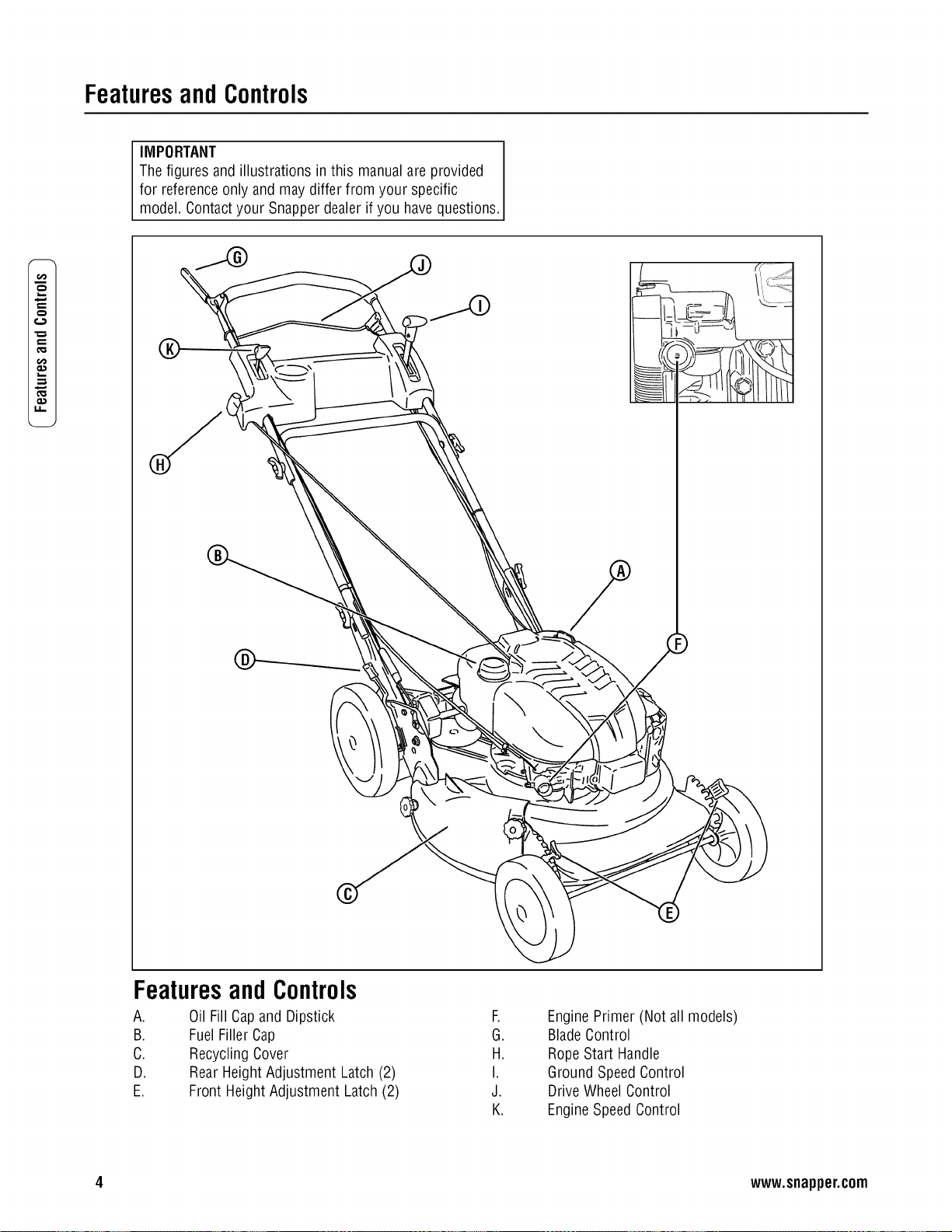
Featuresand Controls
IMPORTANT
The figures and illustrations in this manual are provided
for reference only and may differ from your specific
model. Contactyour Snapper dealer if you have questions.
x,...
0.1
ii
FeaturesandControls
A. Oil Fill Capand Dipstick
B. Fuel Filler Cap
C. RecyclingCover
D. Rear Height Adjustment Latch (2)
E. Front Height Adjustment Latch (2)
F.
G.
H.
I.
J.
K.
Engine Primer (Not all models)
BladeControl
Rope Start Handle
Ground SpeedControl
Drive Wheel Control
EngineSpeedControl
4 www.snapper.com
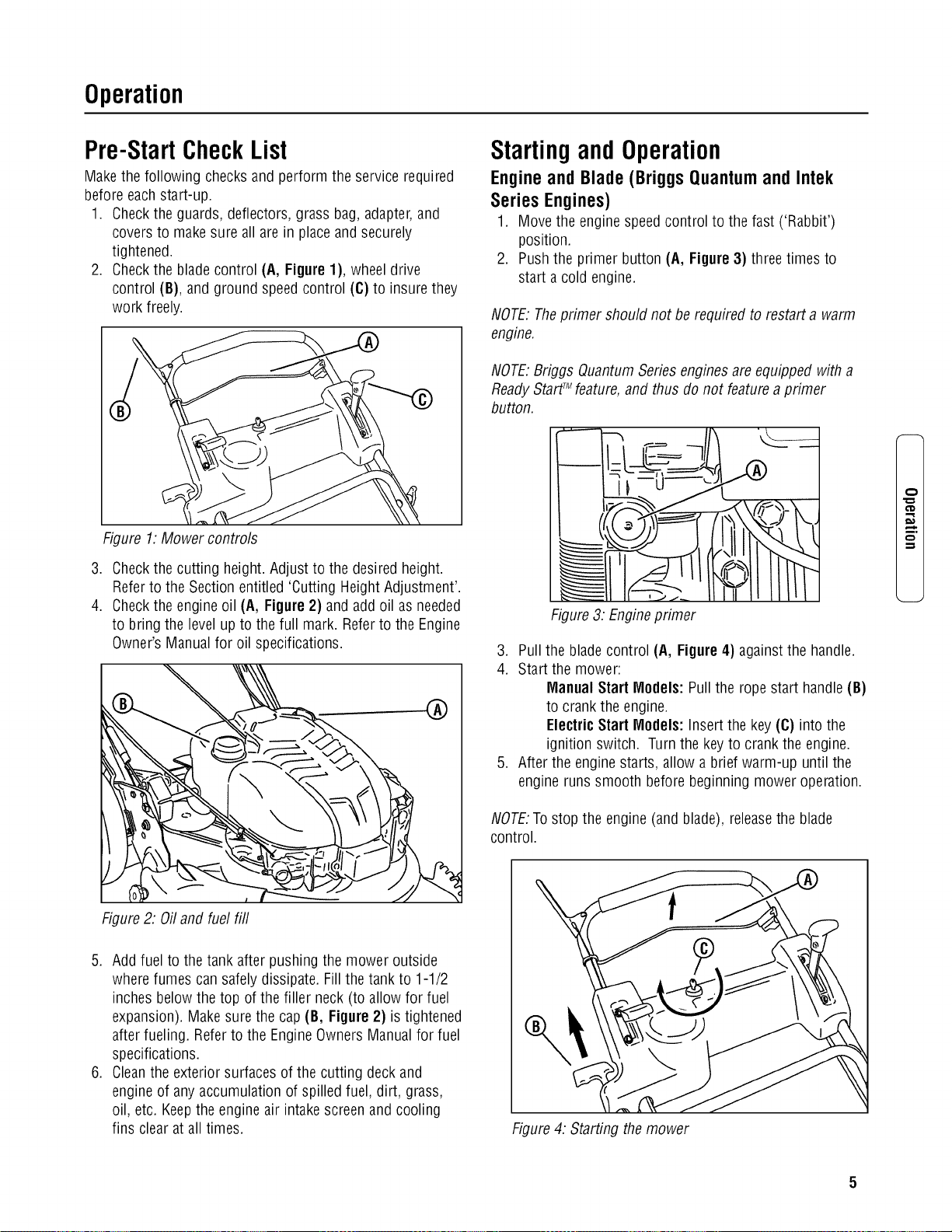
Operation
Pre-StartCheckList
Make the following checks and perform the service required
before each start-up.
1. Checkthe guards, deflectors, grass bag, adapter, and
covers to make sure all are in place and securely
tightened.
2. Checkthe blade control (A, Figure 1), wheel drive
control (B), and ground speed control (C) to insure they
work freely.
Figure 1. Mower controls
3. Checkthe cutting height. Adjust to the desired height.
Refer to the Section entitled 'Cutting Height Adjustment'.
4. Checkthe engineoil (A, Figure 2) and add oil as needed
to bring the level up to the full mark. Refer to the Engine
Owner's Manual for oil specifications.
Startingand Operation
Engine and Blade (Briggs Quantum and Intek
Series Engines)
1. Move the engine speed control to the fast ('Rabbit')
position.
2. Push the primer button (A, Figure 3) three times to
start a cold engine.
NOTE: Theprimer should not be required to restart a warm
engine.
NOTE:Briggs QuantumSeries engines are equipped with a
ReadyStartTMfeaturd and thus do not feature a primer
button.
Figure 3: Engine primer
3. Pull the blade control (A, Figure 4) against the handle.
4. Start the mower:
Manual Start Models: Pullthe rope start handle (B)
to crank the engine.
ElectricStart Models: Insertthe key(C) intothe
ignitionswitch, Turn the key to crank the engine,
5. After the enginestarts, allow a brief warm-up until the
engine runs smooth before beginning mower operation.
NOTE:To stop the engine (and blade), releasethe blade
control.
¢D
m,
Figure 2: Oiland fuel fill
5. Add fuel to the tank after pushing the mower outside
where fumes can safely dissipate. Fill the tank to 1-1/2
inches below the top of the filler neck (to allow for fuel
expansion). Makesure the cap (B, Figure 2) is tightened
after fueling. Referto the Engine Owners Manual for fuel
specifications.
6. Cleanthe exterior surfaces of the cutting deck and
engine of any accumulation of spilled fuel, dirt, grass,
oil, etc. Keep the engine air intake screen and cooling
fins clear at all times.
Figure 4: Starting the mower

Operation(Continued)
t::
€:)
,m
o.1
Startingand Operation(Continued)
Engine and Blade (Briggs DOV Series and
Kawasaki Engines)
1. (Kawasaki Engine only) Make sure the fuel valve(A,
Figure 5) on the engine is open.
Figure 5: Fuel shut-off (Kawasaki engine only)
2. Move the engine speed control past the fast ('Rabbit')
detent to the 'Choke' position.
3. Pull the blade control (A, Figure 4) against the handle.
4. Pull the rope start handle (B) to crank the engine.
5. After the engine starts, allow a brief warm-up until the
engine runs smooth before beginning mower operation.
NOTE.To stop the engine (and blade), releasethe blade
control.
Propelling the Mower
(Self-PropelledModels Only)
1. Start the engine. Refer to the Section entitled "Starting
and Operation - Engineand Blade".
2. Move the ground speedcontrol (A, Figure 6) to the
desired speed position.
3. Squeezethe wheel drive control (B) againstthe handle
to engagethe wheel drive and propel the mower
forward. Forward speed can be adjusted while the
mower is moving by changing the position of the
ground speed control.
Stopping
1. Stop forward motion of the mower by releasingthe
wheel drive control.
2. Stop the engine and blade by releasingthe blade
control.
HandleHeightAdjustment
The height of the mower handle can be adjusted as follows:
1. Loosen the lower nuts (A, Figure 7) on each
lower handle.
Figure 7: Adjusting the handle height
2. Move the handleassembly (B) up or down until the
desired position is achieved.
3. Tighten the lower nuts on each lower handleto maintain
the desired position.
WARNING
DO NOT attempt any maintenance, adjustments or service
with engine and blade running. STOPengine and blade.
Disconnect spark plug wire and secure away from spark
plug. Engine and components are HOT.Avoid serious
burns, allow sufficient time for all components to cool.
Figure 6: Mower drive controls
6 www.snapper.com

Operation(Continued)
WARNING
DONOT attempt any maintenance,adjustments or service
with engine and blade running. STOPengine and blade.
Disconnect spark plug wire and secure away from spark
plug. Engine and components are HOT.Avoid serious
burns, allow sufficient time for all components to cool.
CuttingHeightAdjustment
1. Pull the height adjusting latch (A, Figure8) outward and
move to the desired cutting height.
Figure 8: Adjusting cutting height
2. Set all wheels at the same cutting height. The highest
cutting position is Notch 7 (Figure 9). The lowest
cutting position is Notch 1.
1.25 in 4.00 in
Figure 9: Cutting height settings (approximate)
RecyclingOperation
Note: For best recycling results, cut up to a maximum of 1/3
of grass blade length and recycle ONLYwhen grass is dry.
1. Set all wheels in the highest cutting position (Notch 7).
Referto the Section entitled "Cutting Height
Adjustment".
2. Move the engine speed control to the fast (Rabbit)
position.
3. Move the ground speed control to the slowest speed
setting.
4. Proceed mowing slowly. If the grass is very dense,
lower each rearwheel latch one notch lower than the
front wheel latches to improve recycling performance.
Note: The recycling cover should remain on the machineat
all times, unless alternatedischarge operations are desired,
such as side discharging or bagging.
Removingthe RecyclingCover
1. Removethe knob nuts (A, Figure 10) and internal/
externaltooth lock washers (B) securing the recycling
cover (C) to the mower deck.
2. Remove the cover.
Figure 10. Removing the recycling cover
m.
WARNING
Stop engine and mower blade by releasing the blade
control before adjusting cutting height.

Operation(Continued)
t_
,m
WARNING
DONOT attempt any maintenance,adjustments or service
with engine and blade running. STOPengine and blade.
Disconnect spark plug wire and secure away from spark
plug. Engine and components are HOT.Avoid serious
burns, allow sufficient time for all components to cool.
Installingthe DischargeDeflector
1. Remove the recycling cover. Refer to the Section entitled
"Recycling Operation".
2. Install the deflector (A, Figure 11) to the deck in place
of the recycling cover, making sure that:
• The front hole (B) on the outside front of the
deflector fits over the stud where the front of the
recycling cover was originally secured
• The slot (C) on top of the deflector slips underthe
restraining nut on top of the deck (under the right
front corner of the engine)
• The slot (D) on the inside rear of the deflector slips
onto the stud behind the rear of the discharge
opening, where the rear of the recycling cover was
originally secured.
3. Install the internal/externaltooth lock washers and knob
nuts onto the studs and tighten securely.
Installingthe GrassBagAdapter
(Optional Accessory on Some Models)
1. Removethe recycling cover. Refer to the Section entitled
"Recycling Operation".
2. Install the adapter (A, Figure 12) to the deck in place of
the recycling cover, making sure that:
• The front hole (B) on the outside front of the
adapter fits over the stud where the front of the
recycling cover was originally secured
• The slot (C) on top of the adapter slips under the
restraining nut on top of the deck (under the right
front corner of the engine)
• The slot (D) on the rear of the adapter slips onto
the stud behind the rear of the discharge opening,
where the rear of the recycling cover was
originally secured.
3. Install the internal/externaltooth lock washers and knob
nuts onto the studs and tighten securely.
4. Route the recoil rope around the outside of the rope
guide pulley (E).
Note: The recoil rope may needto be slackened. Referto the
section entitled "Handle Assembly".
Figure 11: Installing the discharge deflector
Figure 12. Installing the grass bag adapter
.
(Kawasaki engines only) Attach the grass bag adapter
standoff (A, Figure 13) between the rope guide pulley
and the engine recoil:
• Removethe right rear bolt (B) from the
engine recoil
• Removethe torx screw and nut securing the rope
guide pulley (C) to the bracket on the bagadapter
• Laythe standoff between the bolt holes in the
engine recoil and the bag adapter pulley bracket.
(Position the standoff so that the bent end (D) is
toward the engine recoil cover.)
8 www.snapper.com
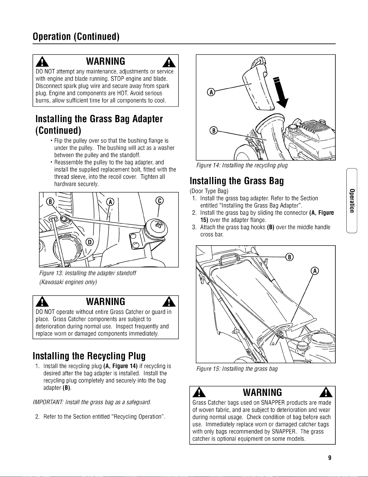
Operation(Continued)
WARNING
DONOT attempt any maintenance,adjustments or service
with engine and blade running. STOPengine and blade.
Disconnect spark plug wire and secure away from spark
plug. Engine and components are HOT.Avoid serious
burns, allow sufficient time for all components to cool.
Installingthe GrassBagAdapter
(Continued)
• Flip the pulley over so that the bushing flange is
under the pulley. The bushing will act as a washer
betweenthe pulley and the standoff.
• Reassemblethe pulley to the bag adapter, and
install the supplied replacementbolt, fitted with the
thread sleeve, into the recoil cover. Tighten all
hardware securely.
Figure 13: Installing the adapter standoff
(Kawasakiengines only)
WARNING
DONOT operate without entire Grass Catcheror guard in
place. Grass Catcher components are subject to
deterioration during normal use. Inspect frequently and
replaceworn or damaged components immediately.
Installingthe RecyclingPlug
1. Install the recycling plug (A, Figure 14) if recycling is
desired after the bag adapter is installed. Install the
recycling plug completely and securely into the bag
adapter (B).
IMPORTANT.Install the grass bag as a safeguard.
2. Refer to the Section entitled "Recycling Operation".
Figure 14. Installing the recycfing plug
Installingthe GrassBag
(Door Type Bag)
1. Install the grass bag adapter.Refer to the Section
entitled "Installing the Grass BagAdapter".
2. Install the grass bag by sliding the connector (A, Figure
15) over the adapter flange.
3. Attach the grass bag hooks (B) over the middle handle
cross bar.
®
Figure 15. Installing the grass bag
WARNING
GrassCatcher bags used on SNAPPERproducts are made
of woven fabric, and are subject to deterioration and wear
during normal usage. Check condition of bag before each
use. Immediately replace worn or damaged catcher bags
with only bags recommended by SNAPPER. The grass
catcher is optional equipment on some models.
m.

Maintenance
p,,
q-.
.m
_E
Maintenance-Introduction
To retain the quality of the mower, use genuine SNAPPER
replacement parts only. Contact a local SNAPPERdealer for
parts and service assistance.For the correct part or
information for a particular mower, always mention the
model and serial number.
WARNING
DONOT attempt any maintenance,adjustments or service
with engine and blade running. STOPengine and blade.
Disconnect spark plug wire and secure away from spark
plug. Engine and components are HOT.Avoid serious
burns, allow sufficient time for all components to cool.
Wear heavy leather gloves when handling or working
around cutting blades. Bladesare extremely sharp and can
causesevere injury.
Service- After First5 Hours
Change Engine Oil
1. Refer to the EngineManual for proper oil specifications,
procedures and proper service intervals.
2. For the simplest/cleanest oil change, simply turn the
mower on its side to drain the oil, as shown. Drain the
oil through the dipstick tube (A, Figure 16) into a
container. Allow sufficient time for all the oil to drain.
Important: Drain the fuel tank before tipping the machine.
DO NOT tip the machinewith the carburetor or spark plug
down. Oil from the crankcasewill saturate the air filter and
causethe engine to be hard to start or not start at all. If
contamination does occur, the air filter will haveto be
replaced.
CheckGreaseLevel in Transmission
1. Removethe transmission fill plug (A, Figure 17). Roll
the machine forward or backward while looking down
into the plug hole.
2. If liquid grease is not visible on the input gear (the small
gear below the plug hole), add an amount, to cover the
gear, of Snapper "00" grease.
Figure 17. Removing the transmission fill plug
Note: Snapper "00" grease (Part No. 7029443) is available at
your Snapper dealer.
Note: Do not spill grease or oil onto the surface of the drive
disc (A, Figure 18).
%
Figure 16: Draining the engine oil
3. Dispose of drain oil properly.
4. Fill the enginewith oil as specified in the Engine Manual.
Do not overfill.
Figure 18: Location of the drive disc
3. Reinstall the transmission plug.
4. Checkthe grease level after each 25 hours of operation.
Important:Drain the fuel tank before tipping the mower. DO
NOTtip the machine with the carburetor or spark plug down.
Oil from the crankcase will saturate the air filter and cause
the engine to be hard to start or not start at all. If
contamination does occur, the air filter will haveto be
replaced.
10 www.snapper.com

Maintenance(Continued)
WARNING
DONOT attempt any maintenance,adjustments or service
with engine and blade running. STOPengine and blade.
Disconnect spark plug wire and secure away from spark
plug. Engine and components are HOT.Avoid serious
burns, allow sufficient time for all components to cool.
Wear heavy leather gloves when handling or working
around cutting blades. Bladesare extremely sharp and can
causesevere injury.
Check Mower Blade
1. Disconnect the spark plug wire and securethe end away
from the plug.
2. Tilt the mower up on its rearwheels for accessto the
blade cap screw (A, Figure19). Do not tilt the mower
with the spark plug or carburetor down.
Important:Drain the fuel tank before tipping the mower. DO
NOTtip the machine with the carburetor or spark plug down.
Oil from the crankcasewill saturate the air filter and cause
the engineto be hard to start or not start at all. If
contamination does occur, the air filter will haveto be
replaced.
3. Checkthe torque of the bladecap screw. Recommended
torque should be 40 ft. Ibs.
4. Checkthe bladefor sharpness, wear and damage. Refer
to the Section entitled "BladeWear Limits".
Figure 19. Tightening the blade cap screw
Check Engine Drive Belt
1. Visually check the engine drive belt for cracking, fraying,
severedor exposed belt strands. If worn or damaged,
replace the belt before operating the mower.
Check Transmission Poly-V Belt
1. Visually check the poly-v belt for cracking, fraying, sev-
ered or exposed belt strands. If worn or damaged,
replacethe belt before operating the mower.
Service- Periodic
Perform all maintenanceas described in the "Service
Schedule" section of this manual.
Engine
Service the engine according to the engine owner's manual.
Air Filter
Referto the engine owner's manual for service instructions.
EngineOil
Referto the engine owner's manual for service instructions.
StorageProcedure
Referto the Engine Owner's Manual for directions regarding
engine storage preparations. Preparethe mower for "end of
season" storage as follows:
1. Drain the fuel from the fuel tank and let the engine run
until all fuel is out of the carburetor.
2. Disconnect and remove the spark plug wire awayfrom
the spark plug before any other preparations are made!
3. Tapeall openings closed to preventspraying water into
the exhaust or air intakes during washing.
4. Tilt the mower up on its rear wheels and thoroughly
clean the underside of the deck. Do not tilt the mower
with the spark plug or carburetor down. Scrapeaway
any accumulation of grass with a putty knife and/or
wire brush.
5. Lubricate all exposed metal with a light coating of oil to
prevent corrosion.
6. On self-propelled models, disconnect the transfer rod
clip and remove the ground speed control rod before
folding the handles.
7. Loosen the handle knobs. Carefully fold the handles
forward, "flexing" the control cables to prevent cable
damage.
8. Store the mower in a shed or other dry area, protected
from weather.
m.
€'D
11

Maintenance(Continued)
,m
_E
WARNING
DONOT attempt any maintenance,adjustments or service
with engine and blade running. STOPengine and blade.
Disconnect spark plug wire and secure away from spark
plug. Engine and components are HOT.Avoid serious
burns, allow sufficient time for all components to cool.
Wear heavy leather gloves when handling or working
around cutting blades. Bladesare extremely sharp and can
causesevere injury.
MowerBladeReplacement
Standard Blade Wear Limit
1. Inspect the blade(Figure 20) frequently for signs of
excessivewear or damage:
(A) New blade
(B) Wear limit (notch starts)
(C) Dangerous condition! Do not use on the mower!
Replacewith a new blade.
Figure 20: Standard blade wear limits
Ninja Blade Wear Limit
1. Inspect the blade(Figure 21) frequently for signs of
excessivewear or damage:
(A) New blade
(B) Wear limit (cracks or notches begin to appearon
tip)
(C) Dangerous condition! Do not use on the mower!
Replacewith a new blade.
WARNING
DONOT use a cutting bladethat shows signs of excessive
wear or damage.Refer to the Section entitled "MOWER
BLADEREPLACEMENT"for proper blade inspection and
service procedures.
Figure 21: Ninja blade wear fimits
BladeSharpening
1. Disconnect the spark plug wire and secure the end away
from the plug.
2. Tilt the mower up on its rear wheels. Do not tilt the
mower with the spark plug or carburetor down.
Important:Drain the fuel tank before tipping the mower. DO
NOTtip the machine with the carburetor or spark plug down.
Oil from the crankcase will saturate the air filter and cause
the engineto be hard to start or not start at all. If
contamination does occur, the air filter will haveto be
replaced.
3. Remove the blade (B, Figure22).
Makesure that
bladehub is seatedI
[betweenfanges J
i
Figure 22: Removing the mower blade
12 www.snapper.com

Maintenance(Continued)
WARNING
DO NOTattempt any maintenance, adjustments or service
with engine and blade running. STOPengineand blade.
Disconnect spark plug wire and secure awayfrom spark
plug. Engineand components are HOT.Avoid serious
burns, allow sufficient time for all components to cool.
BladeSharpening(Continued)
4. Sharpen the bladeon a grinding wheel at an angle of 22
to 28 degrees (B, Figure 23). DO NOTsharpen the blade
beyond the original cutting edge(A).
Do not sharpen
beyond original
cutting edge
Endview of
bladeassembly
Figure 23: Sharpening the mower blade
5. Check blade for balance.If necessary,correct balance by
grinding heavyend of blade.
6. Reinstall blade (B, Figure 22}. Note the correct
assembly order:
(A) Blade hub
(B) Blade
(C) Bladeflange (facing up)
(D) Conewasher (concave side up)
(E) Capscrew
7. Checktorque of blade retaining cap screw.
Recommendedtorque should be 40 ft. Ibs.
Wheel DriveControlAdjustment
(Self-PropelledModelsOnly)
1. The wheel drive control is properly adjusted when there
is 1/16" to 1/8" clearance (G, Figure24) betweenthe
inside of the spring hook (E) and the inside of the clutch
cable eye (C) with the wheel drive control released.
Figure 24: Wheeldrive control adjustment
2. To adjust, unhook the upper spring (D) from the cable
eye and rotate the spring in the direction required to
extend or shorten the spring length.
3. Rehook the upper spring to the cable eye and check
clearance. Repeatthe procedure if required.
Note. Thevinyl spring cover(B) should be kept over the
spring at aft times except for adjustments.
.
If the wheel drive control fails to return quickly to the
"OFF" position when released,check for binding at the
cable holdings located on the side of the right handle.
The upper clip should be located 2" below the upper
knob; the lower clip should be 4" above the lower knob.
The cable should slide freely with the clips installed at
these locations.
m.
€'D
13

Maintenance(Continued)
e,,,
t_
.m
_E
WARNING
DO NOTattempt any maintenance, adjustments or service
with engine and blade running. STOPengineand blade.
Disconnect spark plug wire and secure awayfrom spark
plug. Engineand components are HOT.Avoid serious
burns, allow sufficient time for all components to cool.
Drivenand DriveDiscService
If the mower does not propel itself properly, check for the
following problems:
Figure 25. Wheel drive components
1. Greaseon the drive disc (A, Figure 25) causing
slippage.
2. Broken or disconnected drive spring (B).
3. Driven disc (C) is out of adjustment.
4. Driven disc rubber is worn - does not contact drive disc
properly.
5. Worn Poly-V belt (D) or engine drive belt (E).
If any of the above (1 thru 5) are causing problems, service
as follows:
Cleaning Drive Disc & Driven Disc
If oil or greaseon the drive disc or driven disc is causing
slippage, clean the discs as follows:
1. Wipe away any oil or grease with a clean cloth.
2. Use either an approved grease solvent or hot, soapy
water to clean drive disc or driven disc.
3. Rinse components with clean water.
4. Dry components with a clean cloth.
DriveSpringRepair/Replacement
If the drive spring (A, Figure 26) is loose, reconnect. If the
spring is broken, replacewith a new spring.
Note: Usea pair of needlenose pliers to install the drive
spring.
IMPORTANT:If the drive system continues slipping, refer to
the Troubleshooting section.
Figure 26: Replacingthe drive spring
Driven Disc Adjustment
If the drive disc and driven disc are clean and the mower
drive is still slipping, adjust the driven disc as follows:
1. Move the ground speed control (A, Figure 27) into the
'fast' position.
Figure 27: Theground speed control
14 www.snapper.com

Maintenance(Continued)
WARNING
DO NOTattempt any maintenance, adjustments or service
with engine and blade running. STOPengineand blade.
Disconnect spark plug wire and secure awayfrom spark
plug. Engineand components are HOT.Avoid serious
burns, allow sufficient time for all components to cool.
Driven Disc Adjustment (Continued)
2. Remove the driven disc spring (A, Figure 28) from the
driven disc assembly (B). Also remove the pin and
washer (C) from the transfer rod (D), and removethe
end of the transfer rod from the hole in the driven disc
assembly.
Figure 28: Adjusting the driven disc
3. Slide the driven disc assembly over to 1/8" (A, Figure
29) from the outside edge of the drive disc (B).
4. Loosen the jam nut (A, Figure 38) securing the transfer
rod (B) to the ball joint (C) on the pivot bracket (D).
5. Turn the rod in or out of the ball joint until the end of the
rod aligns with the hole (E) in the driven disc assembly
from which the rod was removed.
IMPORTANT:Do not move the pivot bracket.
6. Reinstall the rod as removed in Step 2. Move the ground
speed control to the 'slow' position, then back to the
'fast' position. Recheckthe 1/8" measurement described
previously. Readjustas needed.Tighten the nut when
finished.
7. Reinstall the driven disc spring to the driven disc
assembly.
Figure 29: Proper driven disc adjustment
Figure 30: Adjusting the transfer rod
Driven Disc Replacement
If the rubber on the driven disc is badly chunked or worn, it
must be replaced. Install a new driven disc as follows:
1. Removethe pin and washer (C, Figure 28) from the
transfer rod (D), and remove the end of the transfer rod
from the hole in the driven disc assembly.
m.
15

Maintenance(Continued)
e,,,
t_
.m
_E
WARNING
DO NOTattempt any maintenance, adjustments or service
with engine and blade running. STOPengineand blade.
Disconnect spark plug wire and secure awayfrom spark
plug. Engineand components are HOT.Avoid serious
burns, allow sufficient time for all components to cool.
Driven Disc Replacement (Continued)
2. Using needle nose pliers, unhook the drive spring (A,
Figure 31) and slide the driven disc assembly off the
hex shaft.
3. Remove the two snap rings (A, Figure 32) which secure
the rubber driven disc (B) to the driven disc assembly.
4. Install a new rubber driven disc onto the driven disc
assembly, and secure with the retaining rings.
5. Reversethe above proceduresfor reassembly and
installation of the driven disc assembly.
Driven Disc Bearing Replacement
IMPORTANT:The bearing on these machines is staked into
the thrust plate. The bearing will haveto be driven out with a
mallet and a large punch. A new bearing with four retaining
screws will haveto be purchased to replace existing bearing.
If the driven disc bearing requires replacement, replace the
bearing as follows:
1. Removethe driven disc assembly. Refer to the Section
entitled "Driven Disc Replacement".
2. Remove both snap rings (A, Figure 32) that secure the
rubber driven disc (B) to the thrust plate.
3. Slide the rubber driven disc hub out of the bearing.
4. Drive out the existing bearing (C).
5. Install a new bearing and secure to the thrust plate with
four retaining screws. Tighten the screws securely.
6. Reassemblethe components in reverse order.
NOTE:Be sure to replace the shim washer (D) when
reassembfingthe driven disc assembly.
Figure 31. Removing the driven disc assembly
Figure 32: Replacing the driven disc
16 www.snapper.com

Maintenance(Continued)
WARNING
DO NOTattempt any maintenance, adjustments or service
with engine and blade running. STOPengineand blade.
Disconnect spark plug wire and secure awayfrom spark
plug. Engineand components are HOT.Avoid serious
burns, allow sufficient time for all components to cool.
Replacing the Bearing On the Pulley End Of the
Hex Shaft
To replace the bearing on the pulley end of the hex shaft,
proceed as follows:
1. Hold the hex shaft with an adjustable wrench held next
to the pulley.
2. Remove the 3/8" hex lock nut (B, Figure33), located on
the outside of the right wheel bracket.
3. Remove the holder (A), O-ring (C) and bearing (D).
4. Install the new bearing.
5. Carefully install the new O-ring over the outside of the
new bearing.
6. Install the bearing holder, and secure with screws.
7. Install the 3/8" hex lock nut.
BeltService
On self-propelled mowers, the engine belt (A, Figure 34)
transmits power from the engine pulley (B) to the drive disc
(C). The drive disc powers the poly-v belt, which engages the
transmission that powers the rearwheels. Should these belts
become worn, they could cause slippage,which would
impair mower performance. The condition of the engine belt
and poly-v belt should be checked after every 25 hours of
mower operation.
Engine Drive Belt Replacement (Stretch Type
Belts)
1. Empty the fuel tank.
2. Note the belt routing (Figure 34). There is no idler
pulley on these models to disconnect.
f ,.. o "_ \//>_ "l,
\% \/ /I//
Figure 34. Engine drive belt routing
i.
€'D
€'D
Figure 33. Replacingthe hex shaft bearing
17

Maintenance(Continued)
e,,,
t_
.m
_E
WARNING
DO NOTattempt any maintenance, adjustments or service
with engine and blade running. STOPengineand blade.
Disconnect spark plug wire and secure awayfrom spark
plug. Engineand components are HOT.Avoid serious
burns, allow sufficient time for all components to cool.
EngineDrive Belt Replacement(StretchType
Belts- Continued)
IMPORTANT:Drain the fuel tank before tipping the mower.
DO NOT tip the machinewith the carburetor or spark plug
down. Oil from the crankcase will saturate the air filter and
causethe engine to be hard to start or not start at all. If
contamination does occur, the air filter will haveto be
replaced.
3. Remove the driven disc. Referto the Section entitled
"Driven Disc Replacement"for driven disc removal
procedure.
4. Drain the fuel tank before tipping the mower. Do not tilt
the mower with the spark plug or carburetor down. Tilt
the mower up on its rear wheels and removethe blade
and bladehub. Assistance from another person may be
necessaryto hold the mower in the tilted position.
5. Hold the slotted end of the drive disc bolt (B, Figure 35)
with a screwdriver and remove the nut (G) and internal
tooth lock washer (F).
6. Remove the belt cover, located under the deck.
7. Lift the drive disc (A) up and remove the worn belt.
8. Loop one end of the new belt over the engine pulley and
insert the other end through the slot in the deck.
9. Loop the belt around the pulley on the bottom of the
drive disc.
10.Reinstall the drive disc and retaining hardware.
IMPORTANT:1) The square shoulder of the drive disc bolt
must fit into the square hole of the bushing. 2) The square
end of bushing must fit into the bracket slot.
11.Reinstall the belt cover and tighten the bolts securely.
12.Reinstall the blade hub and cutter blade. Recommended
torque for the blade cap screw is 40 ft. Ibs.
------4b
)
Figure 35. Removing the drive disc
Transmission Poly-V Belt Replacement
1. Remove the driven disc. Referto the Section entitled
"Replacing Driven Disc Rubber Ring".
2. Note the routing of the old belt around the three pulleys
before removing it.
3. Place the new Poly-V Belt (A, Figure 36) over the end of
the hex shaft (B) and onto the drive pulley (C).
4. Work the belt onto the top of the idler pulley (D).
5. Twist the belt sideways and pull it upward betweenthe
differential bracket (E) and driven pulley (F) and then
down into the pulley groove. Make sure the Poly-V Belt
is above the belt guide (G).
J
Figure 36. Poly-v belt routing
18 www.snapper.com

Maintenance(Continued)
BatteryService
New BatteryPreparation
1. Remove the battery from the carton.
2. Placethe battery in a well ventilated area on a level non-
concrete surface.
3. Remove the battery cell caps. Fill the cells as required
with electrolyte (supplied with battery) to the proper
level. Filling the battery with electrolyte will bring the
battery to 80% charged state.
4. With the cell caps removed, connect the battery charger
to the battery terminals; REDto positive (+) and BLACK
to negative (-) terminal.
IMPORTANT:Neverplace anything in the battery other than
the specified electrolyte.
5. Slow charge the battery at 1 amp for 2 hours to bring
the battery to full charge.
6. After charging, check the level of electrolyte and add as
neededto bring to the proper fluid level.
7. Reinstall the cell caps.
8. Install the battery into the power unit.
9. Connect the positive (+) cable (red) first, from the wiring
harness to the positive terminal (+) on the battery using
the bolt and nut provided in the hardware bag. Connect
the negative (-) cable (black) last, to the negativetermi-
nal (-) on the battery using the bolt and nut. Apply a
small amount of grease over the terminals to prevent
corrosion.
WARNING
DONOToverfill batterywithelectrolyte.Shieldthe positive
terminalwithterminalcoverlocatedonbatteryharness.This
preventsmetalfrom touchingthe positiveterminal,which could
causesparks.Theelectrolyte(acid)producesa highlyexplosive
gas.Keepall sparks,flameandfire awayfrom areawhen
chargingbatteryor whenhandlingelectrolyteor battery.
Electrolyte(acid)is a highlycorrosiveliquid.Weareyeprotection.
Washaffectedareasimmediatelyafterhavingeyeor skincontact
with electrolyte(acid).Batteryacid is corrosive.Rinseemptyacid
containerswithwaterandmutilatebeforediscarding.If acidis
spilledon battery,bench,or clothing,etc.,Flushwith clearwater
andneutralizewith bakingsoda.Neverattemptto chargebattery
while installedonthe walk behind.Neveruse"BOOST"chargers
onthe battery.
BatteryService
1. Removethe battery.
2. Place the battery in a well ventilated areaon a level sur-
face.
3. Using distilled water, refill the cells as required to cover
the cell plates.
4. With the cell caps removed, connect the battery charger
to the battery terminals. Redto positive (+) terminal
and black to negative (-) terminal.
5. Slow charge the battery at 1 amp for 10 hours.
6. If the battery will not accept a charge or is partially
charged after 10 hours of charging at 1 amp, replace
with a new battery.
BatteryStorage
If the Walk Behindis to be stored out of season on its rear
bumper, it is recommendedthe battery be removed, charged
and stored.
1. Removethe battery.
2. Perform battery service.
3. Bring the battery to full charge, if required.
4. Store the battery in an area awayfrom the Walk Behind
on a wood surface. DO NOT STOREBATTERYON A
CONCRETESURFACE.
Battery Testing
There are two types of battery tests: Unloaded and Loaded.
The unloaded test is the procedure that will be discussed. It's
the simplest and most commonly used. An unloadedtest is
made on a battery without discharging current. To perform
unloaded testing, check charge condition using either a
hydrometer or voltmeter.
.
.
Using a voltmeter, voltage readings appear instantly to
show the state of charge. Rememberto hook the posi-
tive leadto the battery's positive terminal, and the nega-
tive leadto the negative terminal.
A hydrometer measuresthe specific gravity of each cell.
The specific gravity tells the degree of charge; generally,
a specific gravity of about 1.265 to 1.280 indicates full
charge. A readingof 1.230 to 1.260 indicates the battery
should be charged. The chart below shows the charge
level as measured by syringe float hydrometer, digital
voltmeter and five ball hydrometer.
Methodsof CheckingBattery Condition
State of Charge SyringeHydrometer Digital Voltmeter Five Ball Hydrometer
100% Chargedw/Sulfate Stop 1.280 12.80v FiveBalls Floating
100% Charged 1.265 12.60v Four Balls Floating
75% Charged 1.210 12.40v Three Balls Floating
50% Charged 1.160 12.10v Two Balls Floating
25% Charged 1.120 11.90v One Ball Floating
0% Charged Lessthan 1.100 Lessthan 11.80v Zero Balls Floating
m,
¢D
€'D
19

,m
ServiceSchedule
ITEM
Engine Oil
Air Pre-Cleaner
Air Cleaner
Spark Plug
EngineCooling
System
Drive Belts
Mower Blade
Mower Deck
Transmission
Grease
Drive Disc
SERVICE
PERFORMED
Check Oil Level
Initial Oil Change
Periodic Oil Change
CleanSponge Element
Cleanor Replace
Replace
CleanShroud & Fins
Check tor Wear and
Tension
Check for wear, Damage
& Replacement
Clean Debris
Accumulation
CheckGrease Level
Periodic GreaseCheck
Check for Wear Damage
and Replacement
REF.
Page5
Page10
Page11
EngineManual
EngineManual
EngineManual
EngineManual
EACH
USE
5
HRS
X
Page11, 17
Page12 X
Page5 X
Page10
Page10
Page13-16
* Changeoil every 25 hours when operating under heavy load or high temperatures.
** Cleanmore often under dusty conditions or when air debris is present.
25
HRS
X_
X**
X**
5O
HRS
lOO
HRS
X
X**
Maintenance/ReplacementParts
EngineSpeed Control (Briggs Engines)
EngineSpeed Control (KawasakiEngines)
BladeControl Cable (Briggs Engines)
BladeControl Cable (KawasakiEngines)
Clutch Pull Cable
Cutter Blade(Air Lift Compatible)
Cutter Blade(Mulching)
Cutter Blade(Not Air Lift Compatible)
Cutter Blade(Ninja - Quad Edge)
Wheel Drive Pulley to Transmission Pulley Belt
Engineto Drive Disc Belt
Cantilever Drive Tire Assembly
Rubber Drive Tire
Parts Manual for 21" Steel Deck Walk Behind Mower Series 19 - Recycling ('R') Series
Parts Manual for 21" Steel Deck Walk Behind Mower Series 19
EACH
SEASON
X
X
X
7074460
7074138
7034608
7074141
7034604
7019795
7017168
7026691
7026407
7012354
7046784
7073528
7041855
7006149
7006150
20 www.snapper.com

Troubleshooting
PROBLEM
Engine Will Not Start Using
Recoil Starter
Engine Will Not Start (Electri(
Start Models)
Engine Stalls or Stops After
Running
Engine Loses Power
Excessive Vibration
IVlowerWill Not IVloveLoss
Of Traction (Self-Propelled
Models)
Cutting Grass Improperly
Poor Grass Discharge
Oil Leaking
PROBABLECAUSE
1. Fuel tank empty. 1.
2. Engine needs choking or priming. 2.
3. Spark plug wire disconnected. 3.
4. Kawasaki Engines Only - Fuel shut-oft in the 'Off' 4.
)osition.
1. Fuel tank empty. 1.
2. Engine needs choking or priming. 2.
3. Spark plug wire disconnected. 3.
4. Wiring harness disconnected. 4.
5. Battery dead. 5.
6. Kawasaki Engines Only - Fuel shut-off in the 'Off' 6.
)osition.
1. Blade control is released or is not being held
securely against handle.
2. Fuel tank empty.
3. Engine air pre-cleaner and or air cleanerdirty.
4. Spark plug detective or gap set improperly.
CORRECTIVEACTION
Fill tuel tank with tresh fuel.
Choke/Prime. Check Engine IVlanualfor Instructions.
Place spark plug wire onto spark plug.
lurn Fuel shut-oft to 'On' position.
Fill tuel tank with tresh tuel.
Choke/Prime. Check Engine Manual for Instructions.
Place spark plug wire onto spark plug.
Connect wiring harness.
Charge or replace battery.
lurn Fuel shut-off to 'On' position.
1. Blade control should be held securely against handle
at all times during operation of mower.
2. Fill with fuel to proper level.
3. Clean tree of all debris.
4. Service spark plug.
5. Water, debris or stale fuel in fuel system. 5.
6. Kawasaki Engines Only - Fuel shut-oft in the 'Ott' 6.
)osition.
1. Engine air pre-cleaner or air cleaner dirty. 1.
2. Spark plug faulty. 2.
3. Water, debris or stale fuel in fuel system. 3.
1. Damaged, out of balance or bent mower blade. 1.
2. Loose blade components. 2.
3. Loose or missing air Iitt (it equipped). 3.
4. Lumpy or trayed belt. 4.
1. Build-up of debris on or around wheel drive 1.
components.
2. Driven disc slipping.
3. Drive belt requires replacement.
4. Damaged transmission.
1. Cutting height too low or high.
2. Engine speed too slow.
3. Forward ground speed too fast.
4. lerraced cut, side to side.
5. Excessive deck pitch, front to rear.
6. Cutting blade dull or damaged.
1. Engine speed too fast. 1.
2. Forward speed too tast. 2.
3. Grass is wet. 3.
4. Excessively worn or damaged blade. 4.
5. Build up of grass clippings and debris under deck. 5.
6. Improper blade installed on deck. 6.
7. Blade installed improperly on deck. 7.
1. Leaking engine case. 1.
2.
Drain and clean fuel system.
lurn Fuel shut-oft to 'On' position.
Clean or replace tilters.
Service spark plug.
Drain and clean fuel system.
Service mower blade.
Service and tighten loose parts.
Replaceair lifts, lighten to proper torque.
Replace belt.
Clean debris.
2. Clean or replace driven disc.
3. Replace drive belt.
4. Contact authorized SNAPPERdealer.
1. Adjust cutting height.
2. Move engine speed control to 'Fast' position.
3. Move ground speed control to a slower speed.
4. Adjust height of cut with height adjust levers.
5. Adjust height of cut with height adjust levers.
6. Sharpen cutting edges or replace blade.
Move engine speed control to 'Fast' position.
IVloveground speed control to a slower speed.
IVlowwhen grass is dry.
Service mower blade.
Clean deck.
Install proper SNAPPEHblade.
Install blade properly.
Contact authorized SNAPPERdealer.
Check and tighten drain plug.
3. IVlakesure dip stick or oil tiller cap is securely in
)lace.
=3"
m.
21

t_
,m
2 YEAR LIMITED WARRANTY
For two (2) years from purchase date for the original purchaser's residential, non-commercial use, SNAPPER,through any
authorizedSNAPPERdealerwill replace,free of charge (except for taxes where applicable), any part or parts found upon
_xamination by the factory at McDonough, Georgia,to be defective in material or workmanship or both.
For ninety (90) days from purchasedate for the original purchaser's commercial, rental, or other non-residential use, SNAP-
PER,through any authorized SNAPPERdealer will replace,free of charge,any part or parts found upon examination by the
[actory at McDonough, Georgia,to be defective in material or workmanship or both.
&ll transportation costs incurred by the purchaser in submitting material to an authorized SNAPPERdealerfor replacement
underthis warranty must be paid by the purchaser.
This warranty does not apply to certain transmissions, to engines and their components, and batteries, as these items arewar-
ranted separately. This warranty does not apply to parts that havebeen damaged by accident, alteration, abuse, improper
lubrication, normal wear, or other causebeyond the control of SNAPPER.This warranty does not cover any machine or com-
ponent part that has been altered or modified changing safety, performance, or durability.
Batteries have a one (1) year warranty period with free replacement if required for one (1) year from the original purchase
date.SNAPPERwill not be responsible for any installation cost incurred. The battery warranty only covers original equipment
batteries and does not cover damageto the battery or machine caused by neglect or abuse, destruction by fire, explosion,
[reezing, overcharging, improper maintenance, or use of improper electrolyte.
There is no other express warranty.
DISCLAIMMEROFWARRANTY
Implied warranties, includingthoseof merchantabilityand fitness for a particular purpose, are limited to two (2) years
[rom purchasedate for the original purchaser'sresidential or other non-commercialuse, and ninety(90) daysfrom pur-
chase for the original purchaser'scommercial, rental or other non-residentialuse, and to the extent permittedby law, any
andall implied warranties are excluded. This is the exclusiveremedy. Liabilities for consequentialdamages, underany
andall warrantiesare excluded.
Somestates do not allow limitations on how long an implied warranty lasts, or do notallow the exclusionor limitation of
incidentalor consequentialdamages, so the abovelimitation or exclusionmay notapply to you.
Thiswarranty gives you specific legal rights, and you may also have other rights which vary from state to state.
WARNING:THE USEOF REPLACEMENTPARTSOTHERTHAN GENUINESNAPPERPARTSMAY IMPAIR THESAFETYOF
SNAPPERPRODUCTSAND WILL VOIDANY LIABILITYANDWARRANTYBYSNAPPERASSOCIATEDWITH THE USEOF
SUCHPARTS.
IMPORTANT:
Pleasefill out the attached SNAPPERProduct Registration Card immediately and mail to:
Snapper'sProductRegistrationCenter, P.O.Box1379, IVlcDonough,Georgia30253
22 www.snapper.com

04
4- SLOPE GUIDE
........ :..../.b" DE_D_... SIGHT AND HOLD THIS GUIDE LEVEL WITH A VERTICAL TREE,
I ".... -'..'.._S A CORNER OF A STRUCTURE, A POWER LINE POLE, OR A FENCE.
j ........................
...... .....................
!
I
I
Operate a walk-behind mower
across the face of slopes,
never up or down slopes.
10 DEGREES 15 DEGREES
Operate a riding mower
up or down slopes, never
across the face of slopes.
On a riding mower to determine if a slope is safe to mow: (1) disengage the blade(s), (2) put the unit in reverse, and (3) try to back straight up the
slope. If you can back up the slope, it is generally safe to mow. However, if you do not feel safe, or if you are not completely sure, use this guide
anddo not mow a slope that is greater than 15 degrees. If the riding mower is used with a pull-behind or rear mounted attachment,
do not operate the und on a slope that is greater than 10 degrees.
A 15 degree slope is a hill that increases in height at approximately 2.5 feet in 10 feet.
A 10 degree slope is a hill that increases in height at approximately 1.7 feet in 10 feet.
Use extreme care at all times, and avoid sudden turns or maneuvers. Follow other instructions in this manual for safety in mowing on
slopes. Operate a riding mower up or down slopes, never across the face of slopes. Operate a walk-behind mower across the face
of slopes, never up or down slopes. Use extra care when operating on or near slopes and obstructions.
................................. _U'T_E'R_fO'U§E'_GP__&_D'E.................................

Notes
24 www.snapper.com

Notes
25

21" STEELDECK
WALKMOWERS
SERIES19
Product Specifications
Deck Size
Height of Cut
Transmission Type (Self-Propelled Models)
Ground Speed (Self-Propelled Models)
Engine Power - Briggs Quantum / DOV
Engine Power- Briggs Intek
Engine Power- Kawasaki
Engine Displacement - Briggs DOV
Engine Displacement - Briggs Quantum / Intek
Engine Displacement - Kawasaki
Fuel Tank Capacity - Briggs (all)
Fuel Tank Capacity - Kawasaki
21 in
1,25- 4 in
Gear
1 -4 mph
6.50ft-lbs (gross)
8.75ft-lbs (gross)
6.0 hp (gross)
160cc
190cc
180cc
1.6 qt
2,1 qt
CommonServiceParts
Cutter Blade(Ninja - Quad)
Drive Belt (Engine)
Drive Belt (Transmission)
Parts Manual (Recycling)
Parts Manual
Part Number
7026407
7046784
7012354
7006149
7006150
EnginePower RatingInformation:The gross power rating for individual gas engine models is labeled in accordancewith
SAE(Society of Automotive Engineers) code J1940 (Small Engine Power & Torque Rating Procedure), and rating perform-
ance has been obtained and corrected in accordancewith SAEJ1995 (Revision 2002-05). Torque values are derived at 3060
RPM; horsepower values are derived at 3600 RPM. Actual gross engine power will be lower and is affected by, among other
things, ambient operating conditions and engine-to-engine variability. Given both the wide array of products on which engines
are placed and the variety of environmental issues applicable to operating the equipment, the gas enginewill not develop the
rated gross power when used in a given piece of power equipment (actual "on-site" or net power). This difference is due to a
variety of factors including, but not limited to, accessories (air cleaner,exhaust, charging, cooling, carburetor, fuel pump,
etc.), application limitations, ambient operating conditions (temperature, humidity, altitude), and engine-to-engine variability.
Due to manufacturing and capacity limitations, Briggs & Stratton may substitute an engine of higher rated power for this
Series engine.
SnapperProducts
535 Macon Street
McDonough, GA30253
26
1-000-935-2967
www.snapper.com