Loading ...
Loading ...
Loading ...
10
20308184
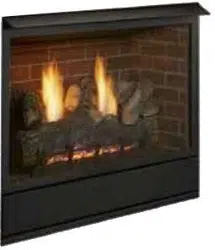
VFF Vent Free Fireplace System
FIREPLACE INSTALLATION
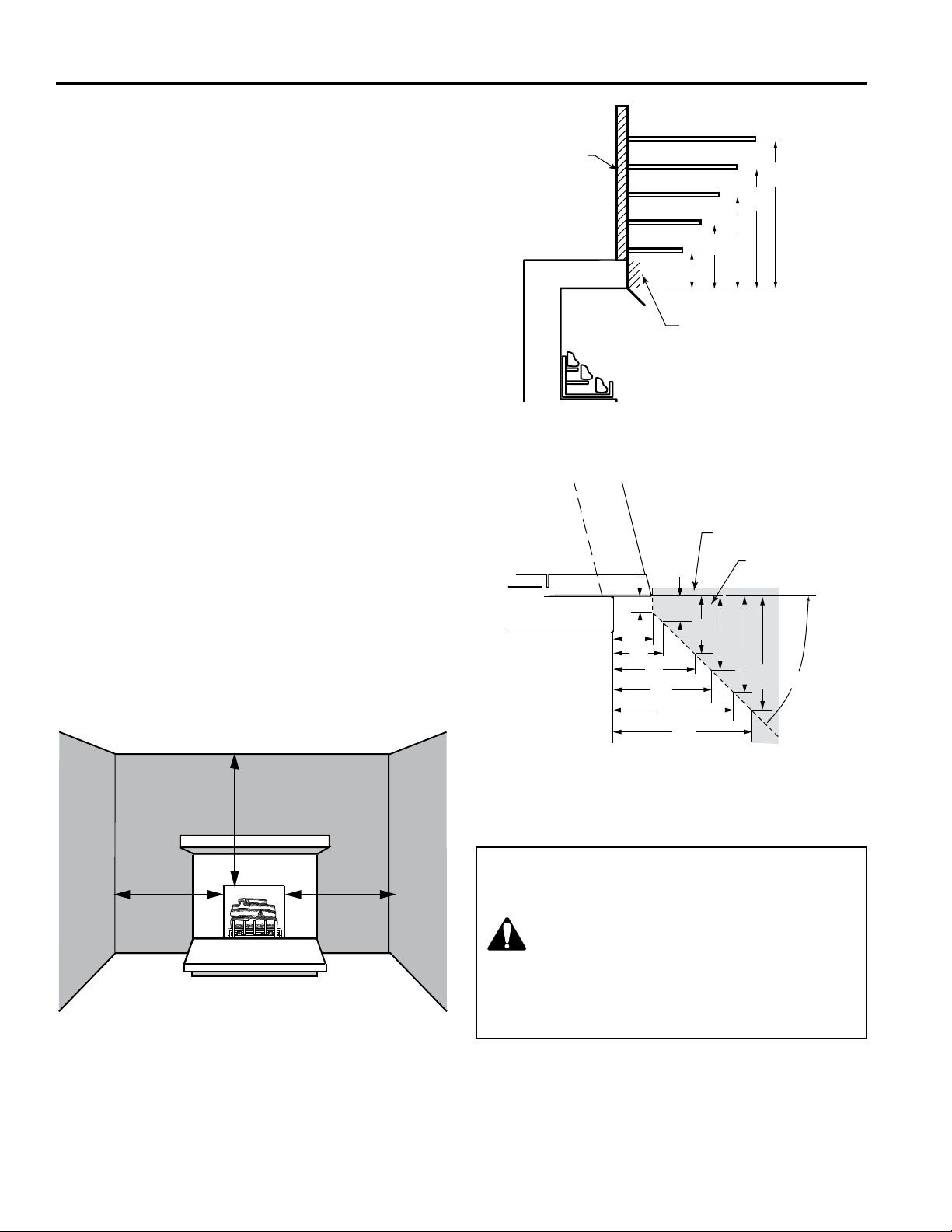
WARNING: The dimensions shown in Figures 6,
7a, and 7b are minimum clearances to maintain
in installing this heater. Left and right
clearances are determined when facing
the front of the heater.
Follow these instructions carefully to ensure
safe installation. Failure to follow instructions
exactly can create a re hazard.
CLEARANCES
Ensure that minimum clearances shown in Figures 6 and
7 are maintained. Left and right clearances are determined
when facing the front of the rebox.
Follow these instructions carefully to ensure safe instal-
lation. Failure to follow these requirements may create a
re hazard.
Sidewall Clearances — The clearance from the inside of
the appliance to any combustible adjacent wall should not
be less than 9" for the VFF32 and VFF36. Figure 6
Ceiling Clearance — The ceiling must be at least 42" from
the top of the rebox opening. Figure 6
Back Wall Clearance — The appliance may be placed
against a combustible back wall.
Floor Clearance — The replace may be installed directly
on a combustible oor or a raised platform of an appropri-
ate height. Do not place replace on carpeting, vinyl, tile or
other soft oor coverings. It may, however, be placed on at
wood, plywood, particle board or other hard surfaces. Be
sure replace rests on a solid continuous oor or platform
with appropriate framing for support and so that no cold
air can enter from under the rebox.
Mantel clearances — The canopy supplied with the unit
must be installed. If a combustible mantel is installed. It
must meet the clearance requirements detailed in Figure 6.
NOTE: The Vermont Castings Group Barrington cabinet
model series BWC400 and BWC500 are specially designed
to comply with all mantel temperature requirements. Any
custom-built mantel must comply with all clearance require-
ments shown in this instruction manual.
9"
Minimum
9"
Minimum
42" Minimum
Figure 6 -
Sidewall and Ceiling Clearances
Figure 7b-
Mantel Leg Clearances
45°
1”
2¹⁄₂”
3”
5”
6”
1¹⁄₂”
3¹⁄₂”
4¹⁄₂”
6”
7¹⁄₂”
7¹⁄₂”
9”
Finish Wall
Combustible
Material Area
2¹⁄₂”
6”
8”
10”
12”
12”
16”
19”
21”
23”
Combustible
material can
contact top of
replace
Non-combustible material
Figure 7a-
Mantel Clearances
Loading ...
Loading ...
Loading ...