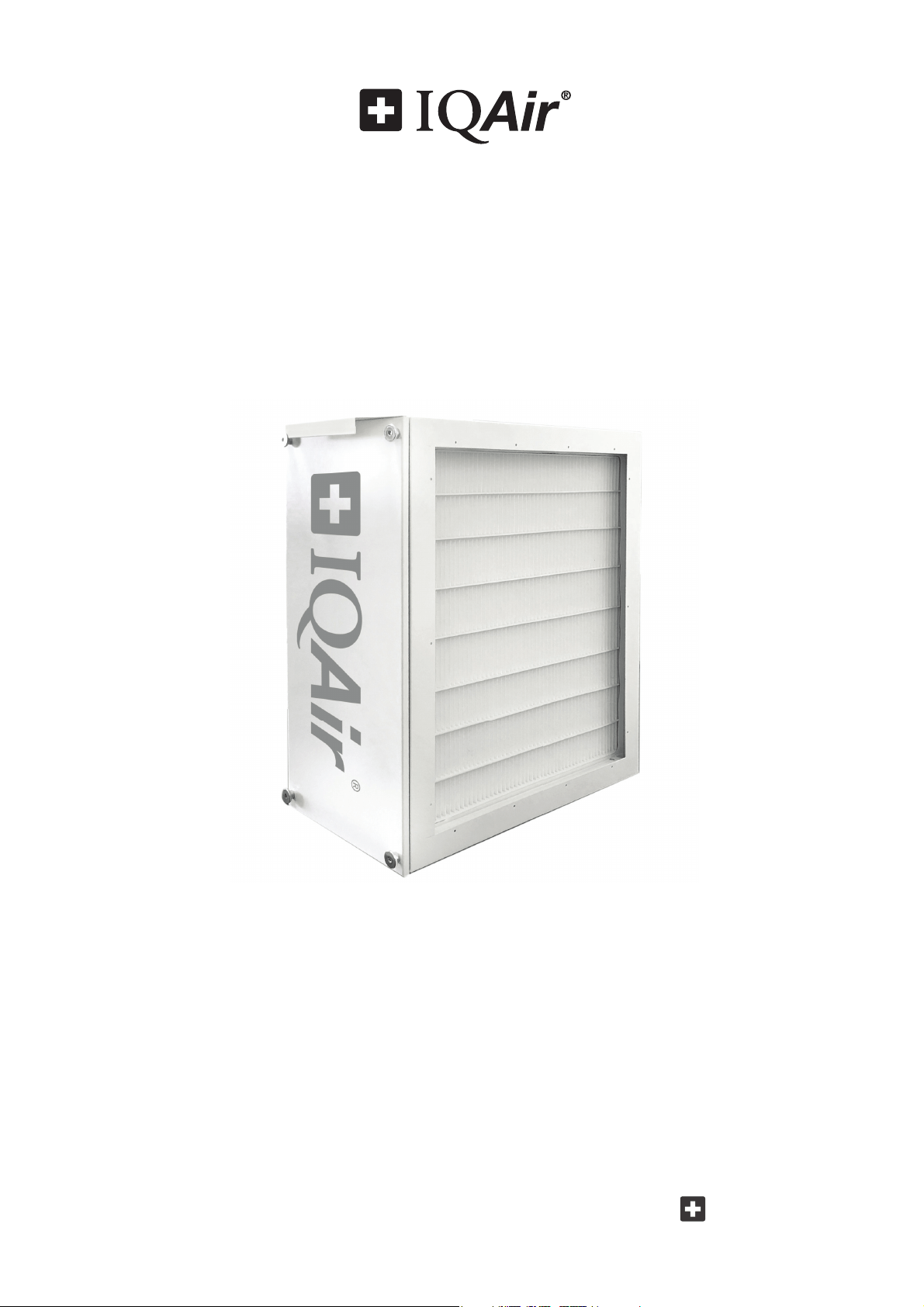
PerfectPro
®
and PerfectPro
®CF
Installation Guide
Swiss Made
HVAC Air Filtration System

2
Safety Precautions - READ AND SAVE THESE INSTRUCTIONS
• Follow professional safety standards and all local codes for plumbing, electrical, and mechanical
considerations.
• Installations must be done in accordance with all applicable standards, building and electrical codes and
must be performed by quali ed personnel only.
• Do not cut into any air conditioning or electrical lines.
• Always disconnect the power supply from the HVAC before working on the system, changing lters, or
cleaning.
• This unit must be installed in an indoor location, protected from the elements.
• Use this unit only in the manner intended by the manufacturer. If you have any questions, contact the
manufacturer at the address or telephone number listed in this document.
• Only use original IQAir lters and accessories. Use of non-IQAir parts or accessories may damage the system
and will void the warranty.
• If the unit is used during construction or renovation or in environments subject to heavy contamination,
check lters regularly for prematurely clogged lters.
• Always wear appropriate protective equipment, such as work gloves and safety goggles for service.
• Save these instructions for future reference.
Warranty Information
This air cleaning system is covered by a two (2) year limited warranty. If within two years from the
original purchase by the end user from the authorized dealer this air cleaning system or any part thereof
(with the exception of lters) is proved to be defective by reason only of faulty workmanship or materials, the
faulty item, or parts thereof, will be repaired or replaced free of charge for labor and materials. The warranty
for replaced parts and service work will expire automatically with the termination of the original system’s
warranty.
This warranty shall not apply to damage caused by misuse, wear and tear, neglect, unauthorized repair,
damage caused by installation, adaptation, modi cation or use in an improper manner or inconsistent with
operating and maintenance instructions, or to wear or deterioration resulting from environmental conditions
or to damage sustained during transport. No liability will be accepted under this warranty for any fault or
damage arising from defective workmanship, if the unit has been serviced, repaired or modi ed by any person
other than the manufacturer’s authorized service personnel or if the system’s serial sticker has been removed or
tampered with.
No shipping, handling or insurance costs for warranty repairs will be refunded. Obvious defects must be com-
municated to the authorized dealer within 10 days of the purchase date.
To secure your warranty rights and prevent transport damage, all products must be returned in original packa-
ging. Please keep the original packaging.
Important Safety Instructions
IQAir® reserves the right to change specifications contained in this document at any time and without prior notice.
©2020 IQAir® Group. All rights reserved. IQAir®, HyperHEPA®, PerfectPro®, and ColdFire® are the registered trademarks of the IQAir® Group. Patents pending.

3
Table of Contents
Page
Safety Precautions 2
Warranty Information 2
Chapter 1 – Air Cleaning Systems and Indoor Air Quality 4
1. 1 Improving Indoor Air Quality 4
1. 2 PerfectPro® Operational Principles 4
1. 3 Application Considerations 5
Chapter 2 – Product Data 6
2. 1 Dimensions and Weight 6
2. 2 Replacement Filter and Order Numbers 6
2. 3 Diagrams and Dimensions 6
Chapter 3 – Parts & Tools 7
3. 1 Equipment Packaging 7
3. 2 Tools Required 7
Chapter 4 – Installation Instructions 8
Chapter 5 – Installation Examples 9
Up- ow furnace 9
Down- ow furnace 9
Horizontal furnace 9
Chapter 6 – Filter Replacment Instructions 10
Chapter 7 – IQAir Technical Support 11
7. 1 Technical Support 11
7. 2 Ordering Replacement Filters 11
7. 3 Contact Information 11
Important Note: In the event of a defect occurring, please contact your point of purchase immediately and
describe the defect. Before any product is returned for service or repair, please seek the express prior permis-
sion from your point of purchase. Your dealer reserves the right to refuse any return shipment which is received
without prior permission. Such shipments may be returned at the original sender’s cost.
The permission to return products does not constitute an acceptance of liability. Upon receipt, the returned
product will be inspected carefully. Should the fault be covered by the terms of this warranty, the product will
be repaired free of charge. Should the fault not be covered by the warranty, a repair and transport quote will be
issued which needs to be accepted in writing before repair work will be carried out.

4
Chapter 1 – Air Cleaning Systems and Indoor Air Quality
Chapter 1 – Air Cleaning Systems and Indoor Air Quality
1.1 Improving Indoor Air Quality
Air cleaning can play an important role when it comes to improving indoor air quality. However, it should be noted
that air cleaning should be used in conjunction with pollution source control and ventilation, wherever possible.
Strategy to improve indoor air quality
To tackle any indoor air quality problem, keep the following three-step strategy in mind:
1. Eliminate or reduce the air pollution source as much as possible. Source control is by far the most e ective way
to improve indoor air quality, since it deals with air pollution at the point of origin.
2. Ensure that su cient fresh air is entering the room from outside. Air cleaners are not a substitution for su cient
ventilation. They are not able to reverse the conversion of oxygen (O
2
) into carbon dioxide (CO
2
), caused by brea-
thing and combustion processes.
3. Ensure the IQAir system can clean enough air to cope with the size of the indoor environment. The actual hourly
air volume cleaned by the system should be at least double the air volume of the indoor space. If the rate at which
pollutants enter the room air is high or the indoor air quality requirements are stringent, the hourly air delivery
of the HVAC system needs to exceed the room air volume several times. To achieve the appropriate level of air
turnover, it may be necessary to employ supplemental stand-alone air cleaners.
Air Cleaning Results
Although air cleaners may be advertised and sold to be suitable for use in speci c indoor environments and to deal
with speci c indoor air quality problems, the manufacturer and distributors make no claim as to the speci c air
cleaning results that are achieved under the user’s individual operating conditions. The air quality improvements
that can be realised with the IQAir® system (as with any air cleaner) in indoor environments depends to a signi cant
degree on individual circumstances, which are out of the control of the manufacturer or distributors. Important
factors which will in uence the air quality improvements that can be achieved in an indoor environment with an air
cleaner include:
• Type of air pollutants present
• Intensity of the pollutant source(s)
• Pollutant concentration
• Size of the indoor environment
• Operating speed of the unit
• Saturation state of the lters in the air cleaner
Consult a quali ed specialist to determine an e ective and comprehensive indoor air quality strategy.
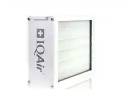
1.2 PerfectPro® Operational Principles
The PerfectPro is a high-performance air cleaning system that connects to the return air duct of a forced air Heating,
Ventilation, and Air Conditioning (HVAC) system.
The PerfectPro system is a mechanical ltration system, and does not generate harmful ozone or charged particles.
As a passive ltration system, it requires the operation of the HVAC to clean the air in the home.
Particle Filtration
The PerfectPro system is equipped with a high performance particle lter that combines high e ciency particle
ltration with low air ow resistance. Filter life is a nominal 1 year, based on 50% duty cycle.
Formaldehyde and Ozone Filtration
The PerfectPro CF is also equipped with a ColdFire® catalyst lter element for the reduction of formaldehyde and
ozone. The catalyst operates at room temperature, and does not require the use of UV lights for activation. Filter life
is a nominal 6 years. The ColdFire® lter is optional, and can be added or removed as desired. The particle lter is
mandatory, and must be in place to provide particle ltration for the HVAC system.
5
Chapter 1 – Air Cleaning Systems and Indoor Air Quality
1.3 Application Considerations
Mount on the Return Side of Air Handler
Mount the PerfectPro on the return side of the air handler. This will help keep the coils clean and reduce maintenance.
Humidi ers
Mount the PerfectPro upstream of humidi ers, so that the water mist does not come in contact with the lters.
UV lights
Germicidal UV lights can cause degradation of the lter. The UV light should be located out of line of sight, or a
minimum of 3 feet from the lter.
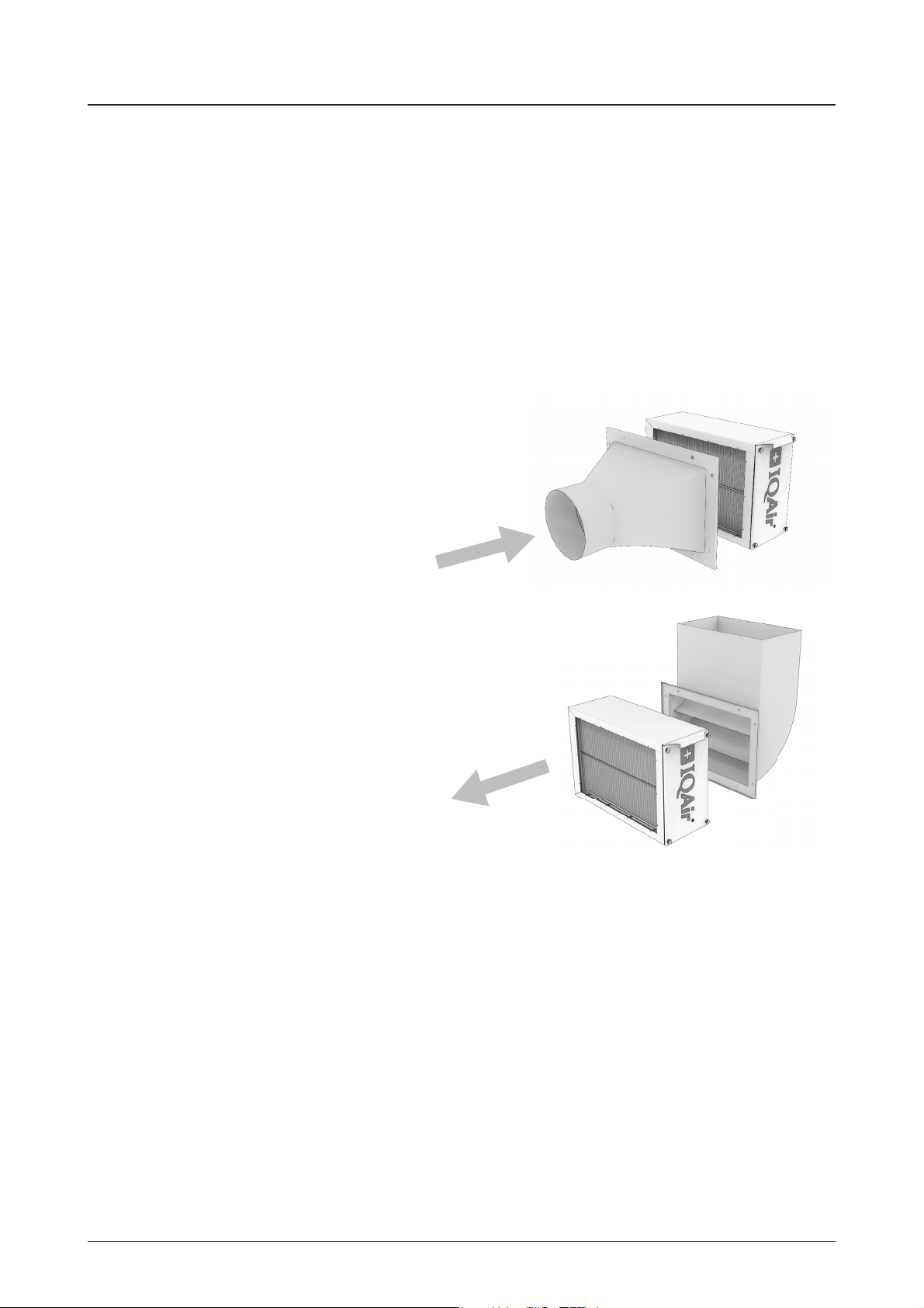
Duct Transitions
Filtration is most e ective when the air ow is even across the
face of the lter. Therefore, if the duct is a di erent size or shape
than the lter cabinet opening, then use a duct transition to help
spread the air ow across the full lter area instead of concentrating
the air ow on a small spot. Use gradual transitions (less than 20°
expansion) to reduce air turbulence and duct friction.
Turning Vanes
If the lter cabinet is installed next to an elbow or angle tting, then
add turning vanes inside the angle to distribute air ow more evenly
across the face of the lter.
Air ow
Air ow
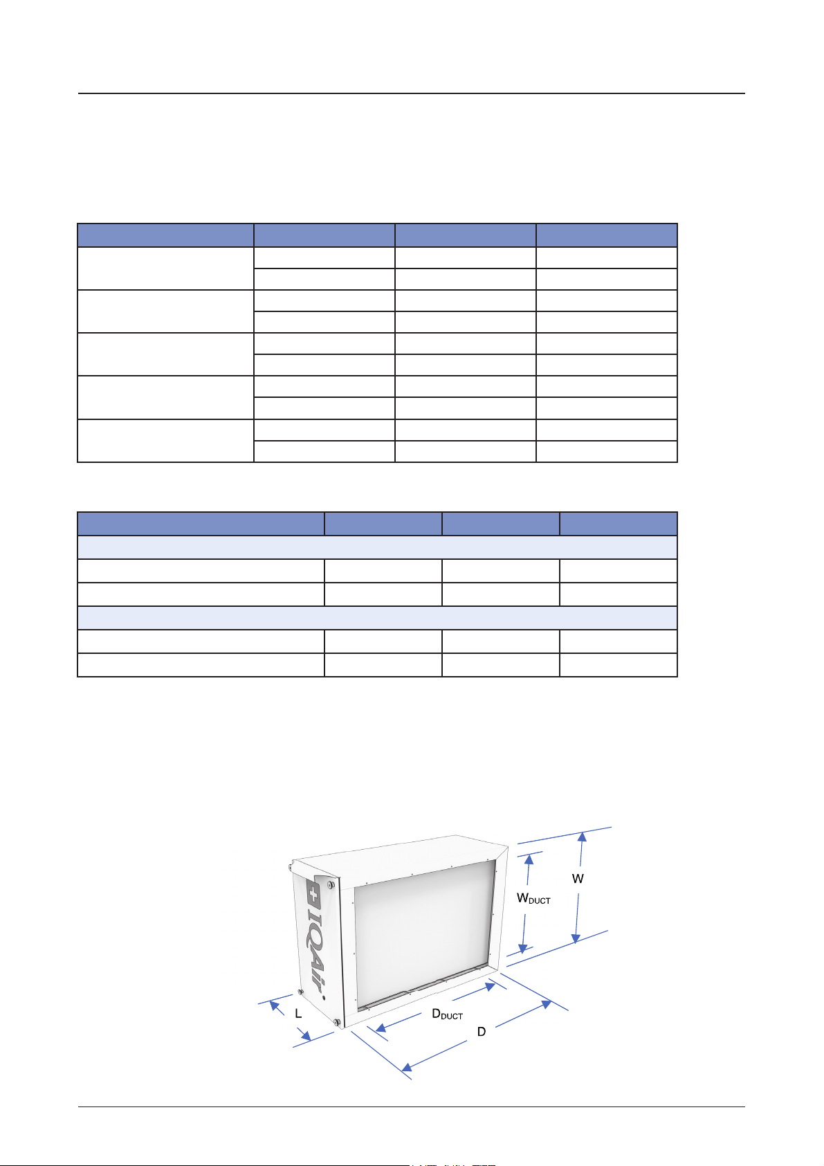
1625 2020 2025
Cabinet Dimensions
(W x D x L)
17.4 x 24.8 x 9.6 in 21.4 x 21.2 x 9.6 in 21.4 x 24.8 x 9.6 in
441 x 630 x 244 mm 543 x 538 x 244 mm 543 x 630 x 244 mm
Duct Opening
(W x D)
14.6 x 21.0 in 18.6 x 17.4 in 18.6 x 21.0 in
371 x 534 mm 473 x 443 mm 473 x 534 mm
Weight
19.0 lbs 19.2 lbs 21.4 lbs
8.6 kg 8.7 kg 9.7 kg
Weight with Filters
Perfect Pro
22.3 lbs 22.7 lbs 25.4 lbs
10.1 kg 10.3 kg 11.5 kg
Weight with Filters
Perfect Pro CF
26.2 lbs 26.9 lbs 30.2 lbs
11.9 kg 12.2 kg 13.7 kg
1625 2020 2025
Devices
PerfectPro
207.80.00.01 207.80.00.02 207.80.00.03
PerfectPro CF
207.80.00.21 207.80.00.22 207.80.00.23
Replacement Filters
Particle Filter
202.12.30.01 202.12.30.02 202.12.30.03
Formaldehyde Catalyst Filter
202.30.20.02 202.30.20.03 202.30.20.04
6
Chapter 2 – Product Data
Chapter 2 – Product Data
2.1 Dimensions & Weight
Table of Dimensions and Weights
2.3 Diagrams and Dimensions
2.2 Replacement Filters
7
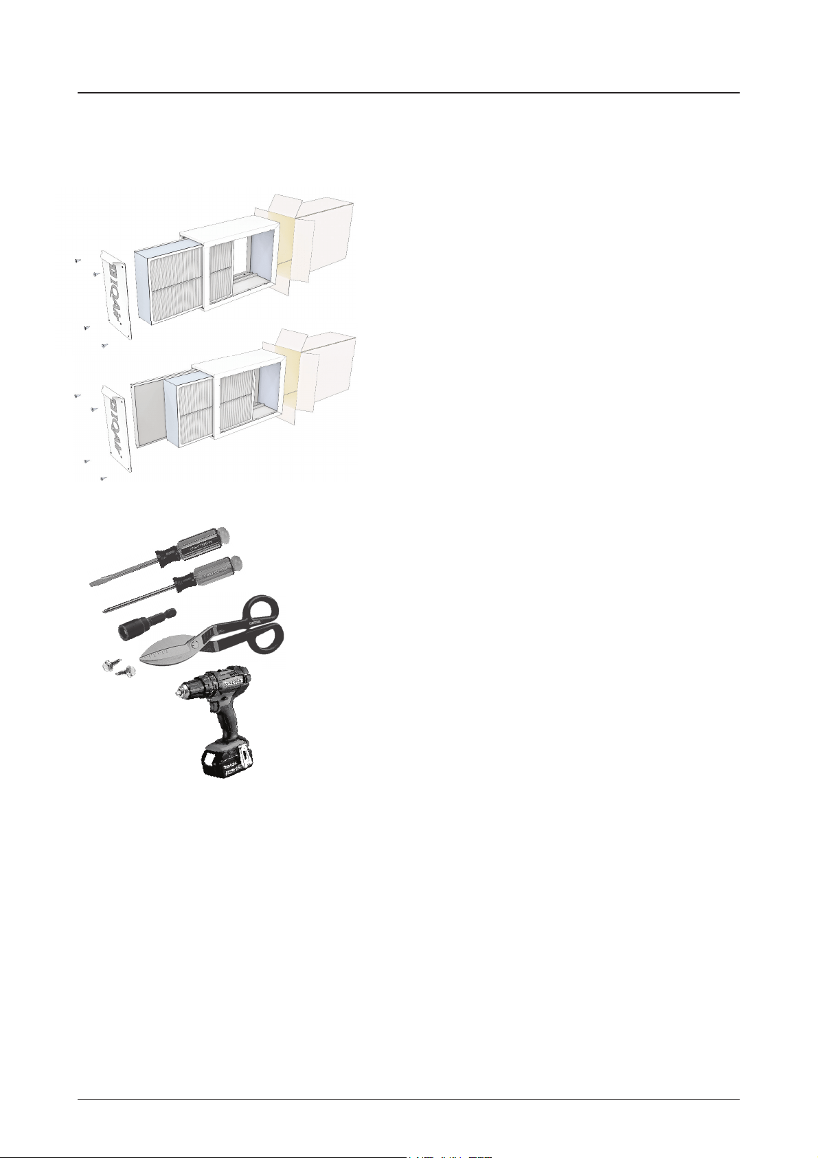
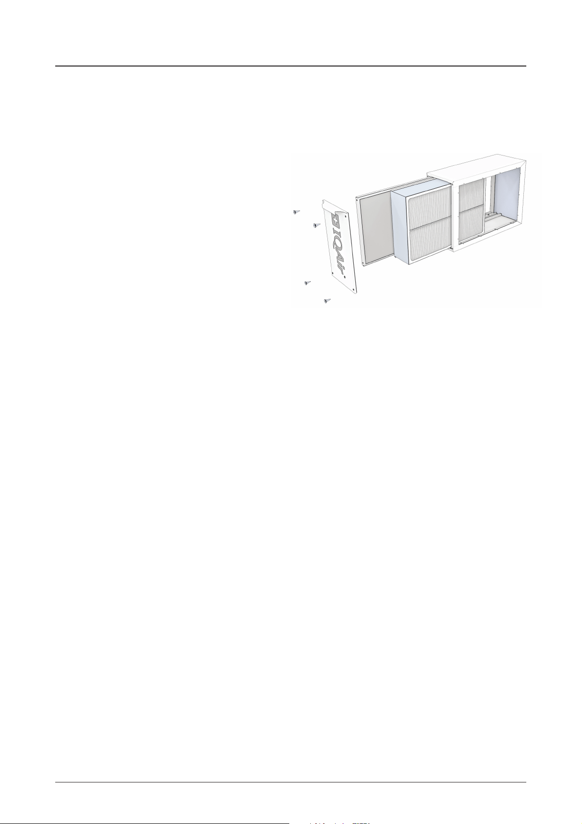
Chapter 3 – Parts & Tools
Chapter 3 – Parts & Tools
3.1 Equipment Packaging
PerfectPro
•
PerfectPro lter cabinet
• Particle Filter (pre-installed in lter cabinet)
• Installation Guide
PerfectPro CF
•
PerfectPro lter cabinet
• Particle Filter (pre-installed in lter cabinet)
• ColdFire catalyst element (pre-installed in lter cabinet)
• Installation Guide
3.2 Tools Required
• Standard screwdriver
• Philips screwdriver
• ¼” hex driver
• Metal cutter
• Power drill & drill bits
• ¼” hex head (#8 x ½” sheet metal screws)
• Foil tape or duct sealant
Additional equipment, such as special wall anchors and
screws, may be required for your application. Please plan
accordingly.

8
Chapter 4 –Installation Instructions
Chapter 4 – Installation Instructions
WARNING:
Always shut o the electrical power supply to the HVAC before working on the appliance.
1.
Remove the PerfectPro from the carton
2. Remove the access panel door from the lter cabinet.
The door is secured with four (4pcs) thumbscrews.
3. Remove the lter(s) from the lter cabinet.
Caution: do not touch the surface of the catalyst lter element.
4. Inspect the installation area. Remove existing lters or systems
that may add additional pressure drop to the system.
5. Choose an installation location between the main return duct and the furnace. Position the lter cabinet so
that the access panel is readily accessible for checking and replacing the lter. Allow at least 26 inches (660 mm)
clearance in front of the lter cabinet.
6. Orient the lter cabinet so the wide lter channel (for the particle lter) is on the air inlet side. The narrow lter
channel (for the catalyst lter) should be on the side closest to the air handler. See also the air ow direction
arrow on the lter channel
7. Attach ducting. Duct transitions may be necessary to properly mount the lter cabinet. Be sure to follow the
local installation codes.
8. When the lter cabinet is mounted directly to the air handler or existing duct, mark the inside opening of the
lter cabinet and all mounting screw locations. Drill the marked mounting holes with a 1/8” diameter drill bit.
Remove the marked lter cabinet opening with metal cutting shears or equivalent.
9. Attach the lter cabinet to the air handler or ductwork using ¼” hex head sheet metal screws (#8 x ½”).
10. Seal the lter cabinet and/or duct connections with foil tape or equivalent.
Important: all leaks on the return side of the system may cause dirty air to leak into the return air stream.
Leakage also occurs in many air handlers via the blower door. The blower door should also be sealed with foil
tape for the best air cleaning results.
11. Write the installation date on the lter labels, and reinstall the lter(s) in their respective lter channels.
The lter labels should be visible when installed, and the air ow direction arrows should match the arrow on
the lter channel.
12. Reattach the access panel door to the lter cabinet. The door is secured with four (4pcs) thumbscrews.
13. Check and inspect the system for leakage.
14. Place the HVAC back into service. HVAC must operate within the HVAC manufacturer’s recommended tempe-
rature and pressure drop requirements.
15. Register warranty online at www.iqair.com/support
9
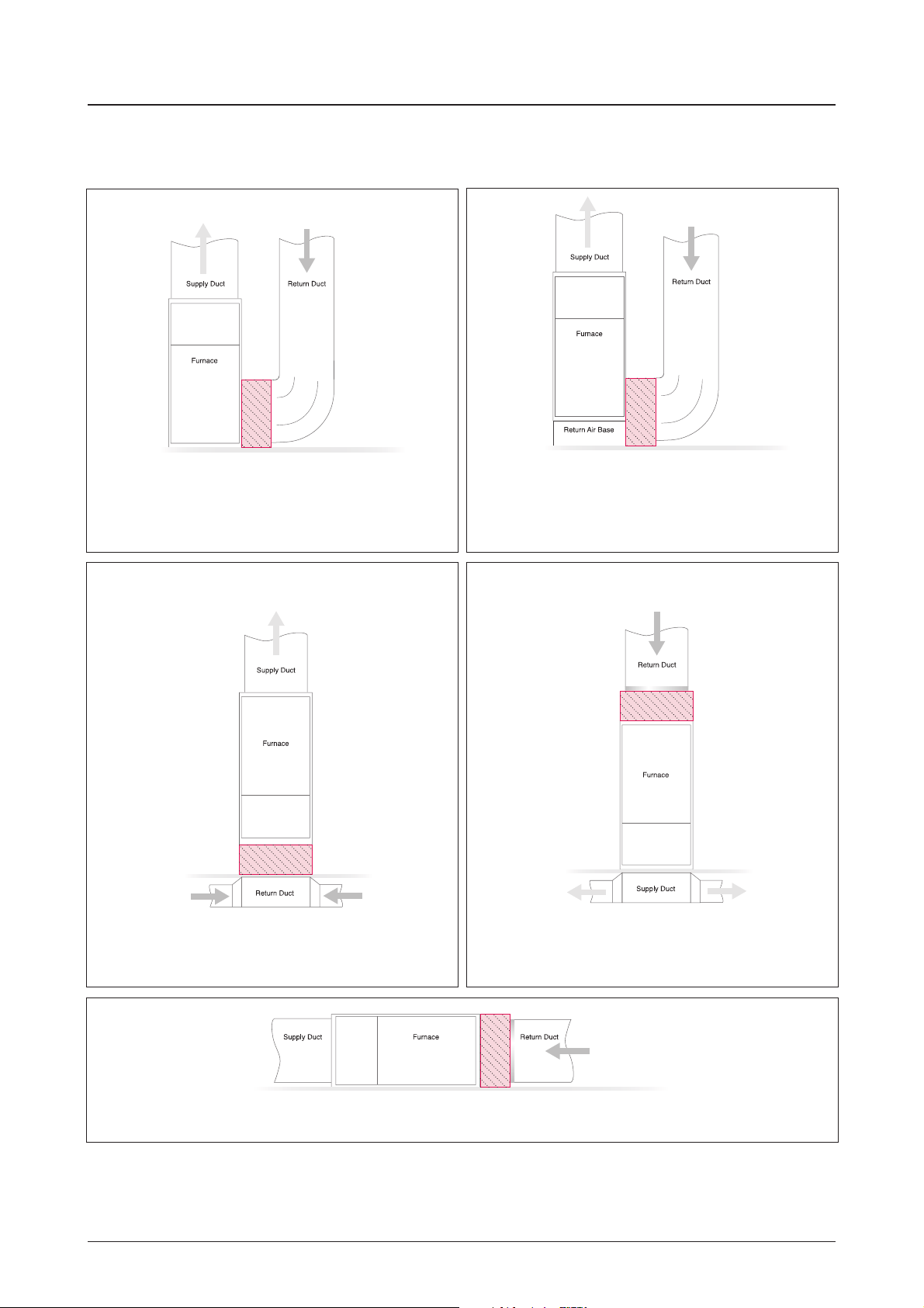
Chapter 5 –Installation Examples
Chapter 5 – Installation Examples
Up-Flow Furnace
Filter system is installed vertically and return air enters
the furnace side inlet (up to 4 ton application).
Up-Flow Furnace (5 ton application)
Filter system is installed vertically and return air enters
the furnace side inlet (5 ton application).
Up-Flow Furnace
Filter system is installed horizontally beneath the furnace.
Return air enters from the bottom.
Down-Flow Furnace
Filter system is installed horizontally in the return
air duct just above the furnace.
Horizontal Furnace
Filter system is installed vertically in the return air duct near the furnace.
10
Chapter 6 – Filter Replacement Instructions
Chapter 6 – Filter Replacement Instructions
WARNING:
Always shut o the electrical power supply to the HVAC before working on the appliance.
Caution: Wear dust mask and gloves to reduce exposure
to dust and other pollutants from lters.
1. Remove the access panel door from the lter cabinet.
The door is secured with four (4pcs) thumbscrews.
2. Remove the Particle Filter. Dispose of used lter per
local laws or regulations.
3. (As needed) Remove the catalyst lter element.
(The catalyst lter element has a nominal 6 year lter
life.) Dispose of used lter per local laws or regulations.
Caution: do not touch the surface of the catalyst
lter element.
4. Write the installation date on the lter label(s).
5. (As needed) Insert new catalyst lter element in the narrow channel. Ensure that the lter label is visible when
installed, and the air ow direction arrow matches the arrow on the adjacent particle lter channel.
6. Insert new particle lter. The lter label should be visible when installed, and the air ow direction arrows should
point in the same direction as the arrow on the formaldehyde catalyst element.
7. Reattach the access panel door to the lter cabinet. The door is secured with four (4pcs) thumbscrews.

Chapter 7– Technical Support
11
Chapter 7 – Technical Support
7.1 Technical Support
Should technical questions or issues arise during or after the warranty period, please contact your local IQAir dealer.
To expedite your service request, please have the following information ready when contacting us:
•
IQAir model, item number and lot number (found on the lter rack)
•
Your details (name, address, phone, email)
•
Date of purchase
•
Description of issue
7.2 Ordering Replacement Filters
For all your lter replacement needs, please contact your local IQAir dealer.
7.3 Contact Information
For further information on installation and technical issues, please contact the IQAir technical support center for your
region:
North America (United States, Canada and Mexico)
IQAir North America, Inc.
Technical Support
14351 Firestone Blvd
La Mirada, CA 90638
USA
Tel: 1-888-560-1020
www.iqair.com/support
International
INCEN AG
Technical Support
Hauptstrasse 100
CH-9422 Staad
Switzerland
Email: [email protected]
IQAir China:
DRC Liangmaqiao Diplomatic O ce Building, Suite 1305B
No. 19 Dongfang Dong Road
Chaoyang District
100600 Beijing
Tel.: 400 108 5117

www.iqair.com
Swiss Made
208.08.01.01 PerfectPro & PerfectPro CF Installation Guide EN 210507