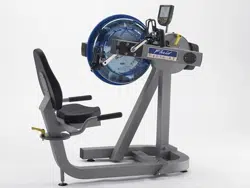
Owners Manual
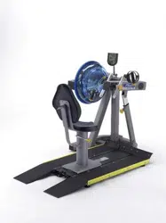
Wheelchair Accessible
2
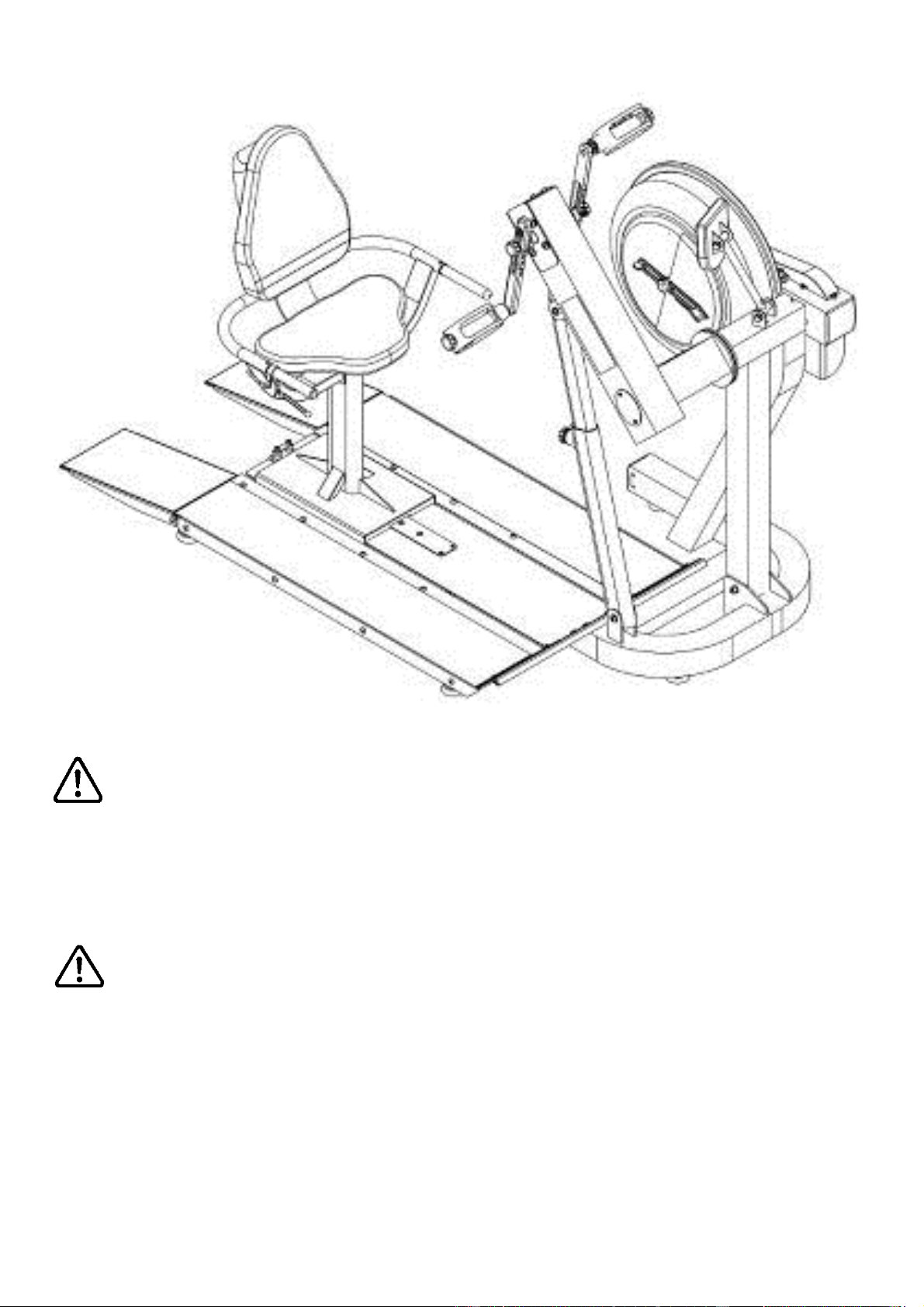
Do not remove hands while crank is in motion. The crank will
continue to rotate and could cause injury.
As with any piece of fitness equipment, consult a physician be-
fore beginning your E920 exercise program.
CAUTION
WARNING

3
Contents
Box Contents
Assembly Instructions
Baseplate Addendum
Seat Assemby
Attaching Armrest Lower frame
Attaching Armrest cable to Cable Pivot
Install Seat Back and Seat
Install Seat onto Baseplate
Control Arm
Slider Arm Installation Instructions
Using Slider Arm
Tank Filling and Water Treatment
Long Term Water Treatment and Basic Operation
Rower Ergometer
Using the First Degree Fitness USB Interface
Maintenance chart
Troubleshooting
Tank Belt Adjustment
Warranty
4
6
7
9
10
12
13
14
15
16
19
20
21
22
23
24
25
26
27
4
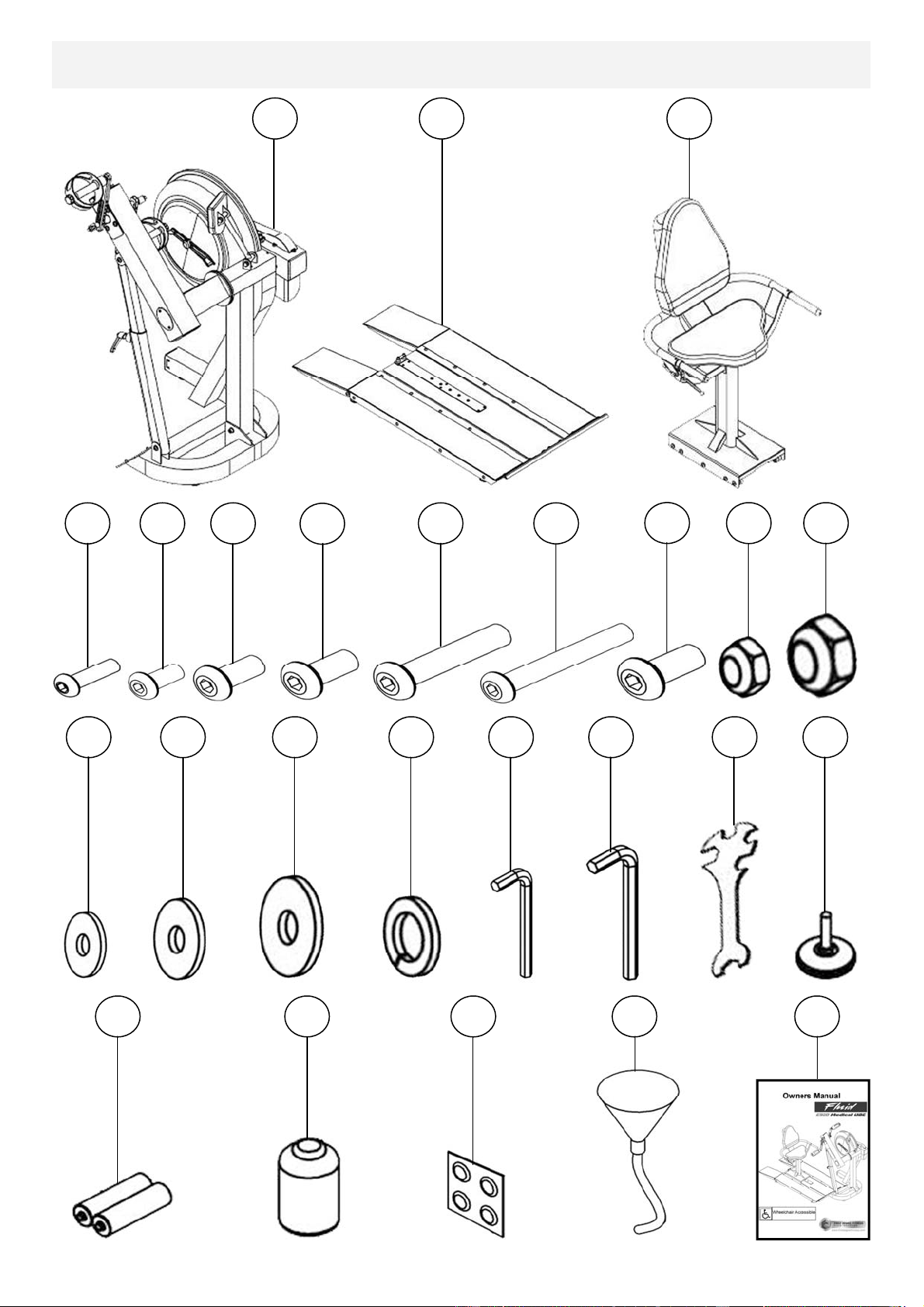
Box Contents
1
11
2
3
4
5
6
8
9
12
20
19
18
17
16
15
14
13
21
22
23
24
25
7
10

5
Item Qty Description Item Qty Description
1 1
Main Frame with Telescoping
Tube and Internal Gas Assist
Shock
14 8 M8 Washer
2 1 Baseplate (Install P-7) 15 3 M10 Washer
3 1 Seat (Install P-9) 16 4 M8 Springs Washer
4 8 M6x20mm bolt 17 1 4mm Allen Key
5 4 M8x15mm bolt 18 1 6mm Allen Key
6 8 M8x20mm bolt 19 1 Multi-tool
7 5 M8x25mm bolt 20 9 Frame Levelers
8 10 M8x45mm bolt 21 2 AA Batteries
12 2 M10 Nylock Nut 25 1 Owners Manual
9 1 M8x70mm bolt 22 1 Touch up paint
10 4 M10x20mm bolt 23 4 Water Treatment Tablet
11 7 M8 Nylock Nut 24 1 Funnel and Hose
13 8 M6 Washer
6
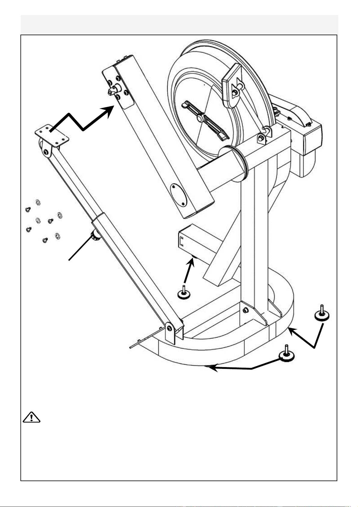
Assembly Instructions
Adjuster Knob
4x M8x15mm Bolts
and 4x M8 Spring
Washers
3x Foot Leveler
Remove contents from box. Attach telescoping tube to the underside of the control
arm using 4x M8x15mm bolts[5] and 4x M8 spring washers[16].
The control arm is heavy and will swing freely during this stage of assembly.
The adjuster knob is pre-tightened from the factory in the optimal
position for assembly in relation to the control arm. Do not loosen the Adjuster knob
until the telescoping tube has been safely secured to the underside of the control
arm.
Thread the 3x foot levelers[20] into underside of base. Adjust as required.
CAUTION
7
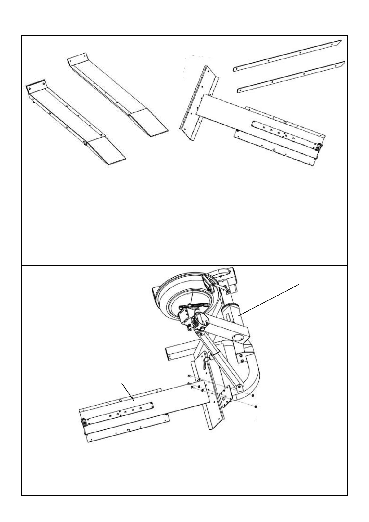
Baseplate Addendum
T-track
E 920 Mainframe
Step 1: Bolt the T-Track to the Mainframe as shown, using 3x M10x20mm bolt
[10], 2x M10 Nut[12] and 3x M10 washer[15].
Secure tightly.
CONTENTS:
Note hardware bolt pack is used for both Seat Assembly and Baseplate.
Remove contents from box and make sure all parts are present. Contents will in-
clude the T-track, left/right side ramps and bolt pack (note, this may also be located
with Seat Assembly).
Locate the T-track, and from the bolt pack the following:
M10x20mm bolt 3x
M10 Nut 2x
M10 Washer 3x
Ramp Left
Ramp Right
T-Track
PVC Sidecovers
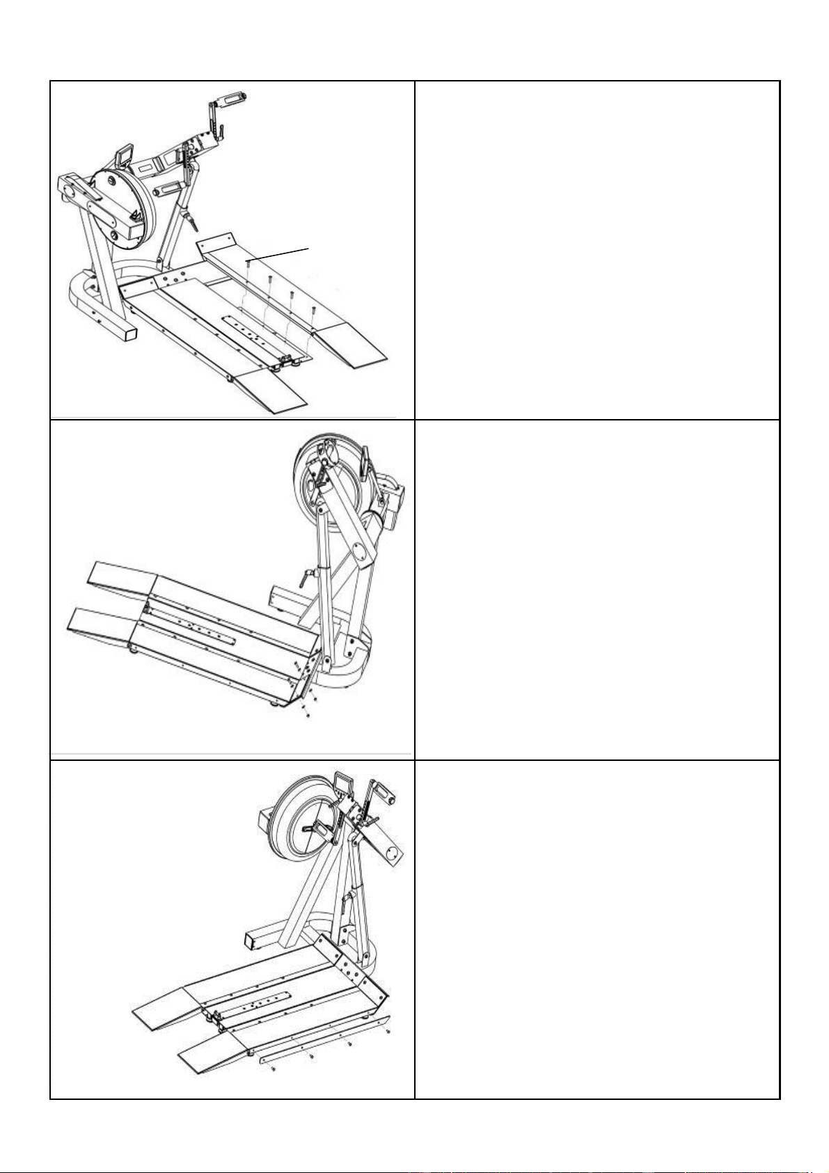
8
M8x45mm bolts
Step 2: Attach Left and Right ramps to
the T-track using 8x M8x45mm bolts
Step 3: Once the Left and Right ramps
have been installed to the sides of the T-
track, secure the front end of each ramp
as shown using 4x M8x25 bolt[7], 4x
M8 Nylock nut[11] and 4x M8 washer
[14].
Step 4: Install Yellow PVC side covers
using 8x20mm bolt[6].
PVC side covers
9
Seat back
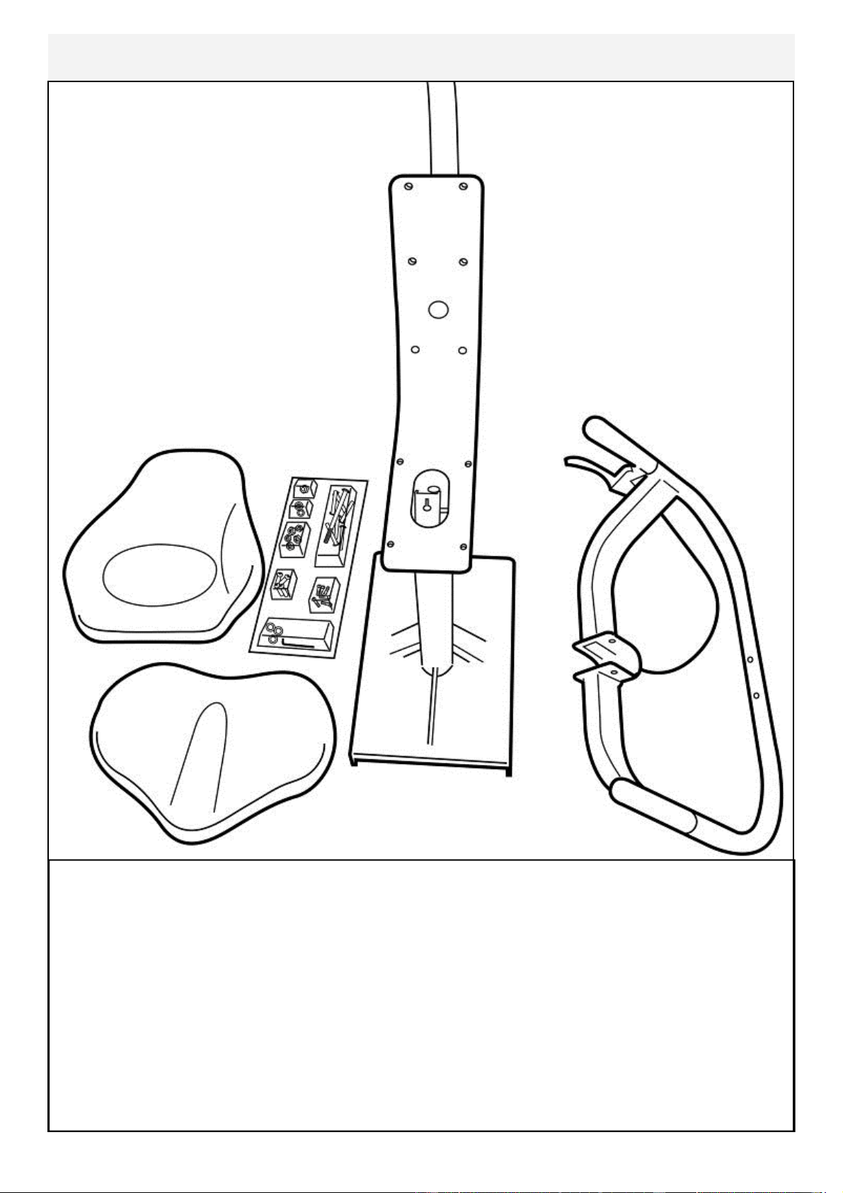
Seat Assembly
CONTENTS:
1x Seat Main Frame 1x Lower Seat
1x Armrest Assembly 1x Upper Seat back
1x Bolt Pack (Note Bolts/Washers/Nuts are for both Seat and Footplate)
You will need the Lower Frame, Armrest Assembly and the following bolts/
washers/nuts from the bolt Pack:
1x M8x70mm Bolt 3x M8 Nylock Nut
1x M8x25mm Bolt 1x M8 Washer
Bolt Pack
Seat
Armrest Assembly
Seat Main Frame
10
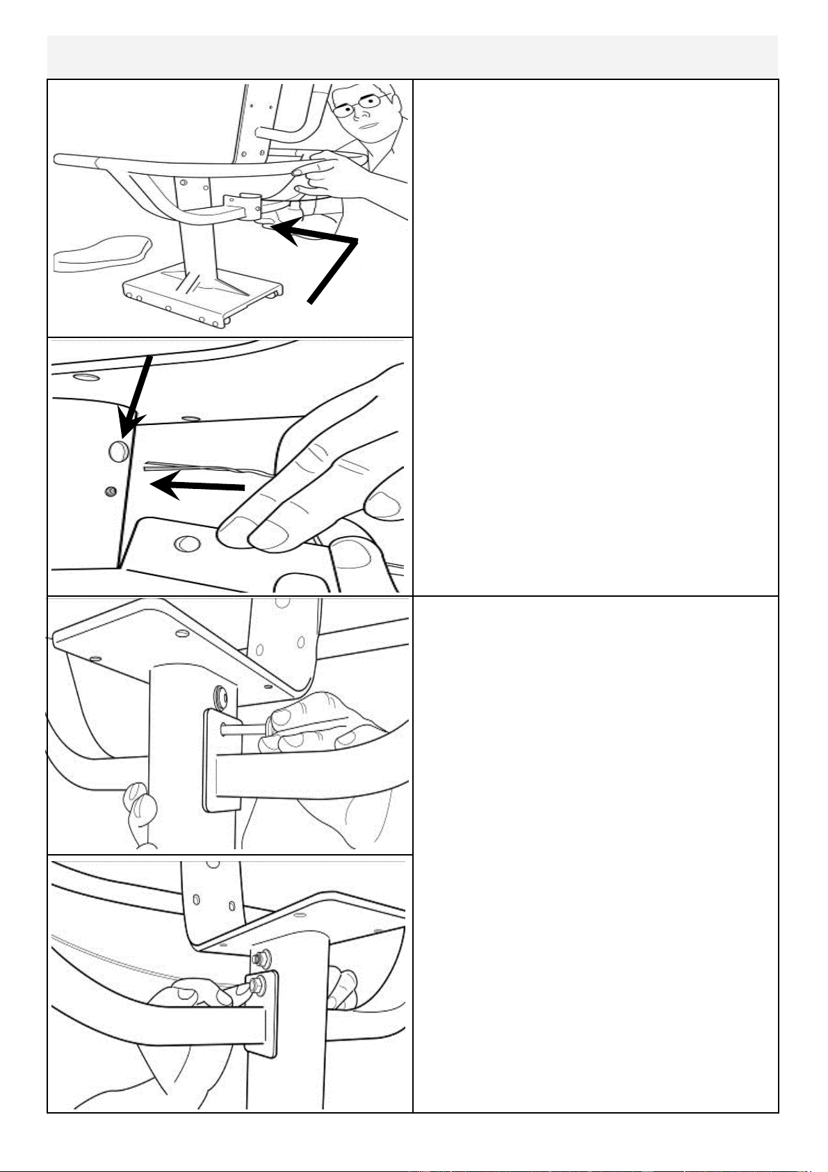
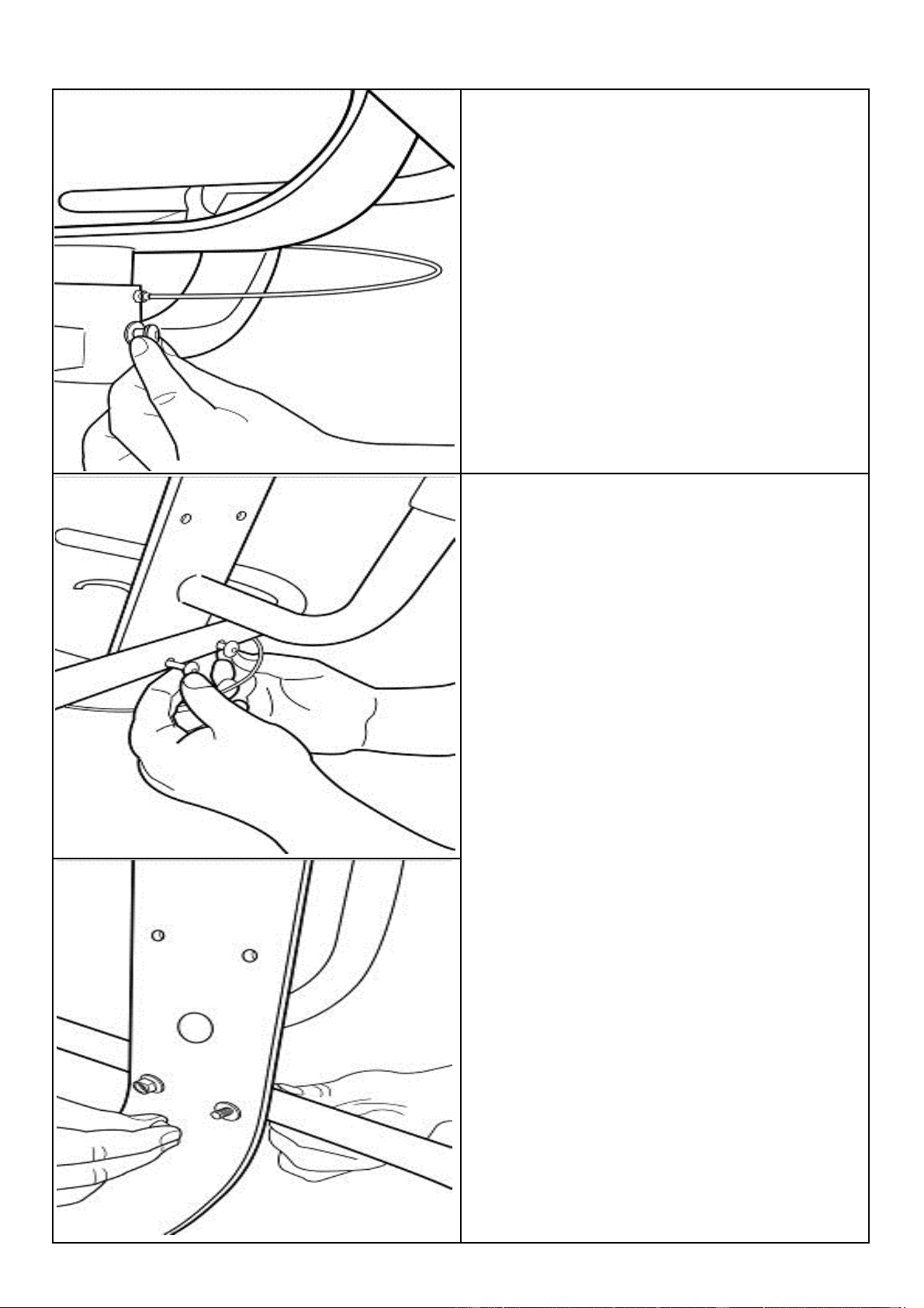
Mount the Armrest onto the Lower frame
from behind as shown.
Important! Before securing bolts (see
following page), thread the plastic tie at-
tached to the armrest cable through the
hole as shown right.
Secure Armrest with M8x70mm Bolt[9],
M8 Nylock Nut[11] and M8 Washer[14]
as shown
Plastic tie
Attaching Armrest to Lower frame
11
M8x25mm Bolt[7] and M8 Washer[14]
2x M8x45mm Bolt[8],2x M8 Nylock Nut
[11] and 2x M8 Washer[14]
12
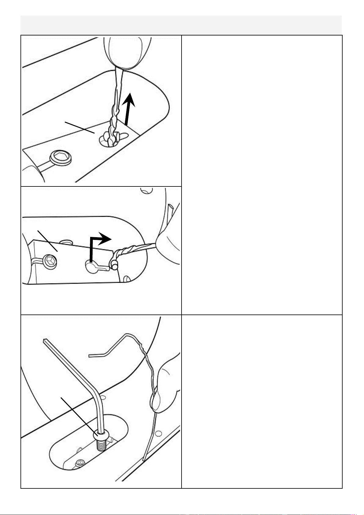
Attaching Armrest cable to Cable Pivot
Now secure the cable end with the
M10x20mm bolt[6]. Before tightening
the bolt into position, the plastic tie end
can be discarded
Locate plastic tie, then depress Cable
Pivot forward to allow plastic tie to be
pulled through the hole in front. Once
the cable end is through the hole, slide it
forward as shown upper right to prevent
cable end from slipping back through.
Cable Pivot
Cable Pivot
Plastic tie
M10x25mm
bolt
13
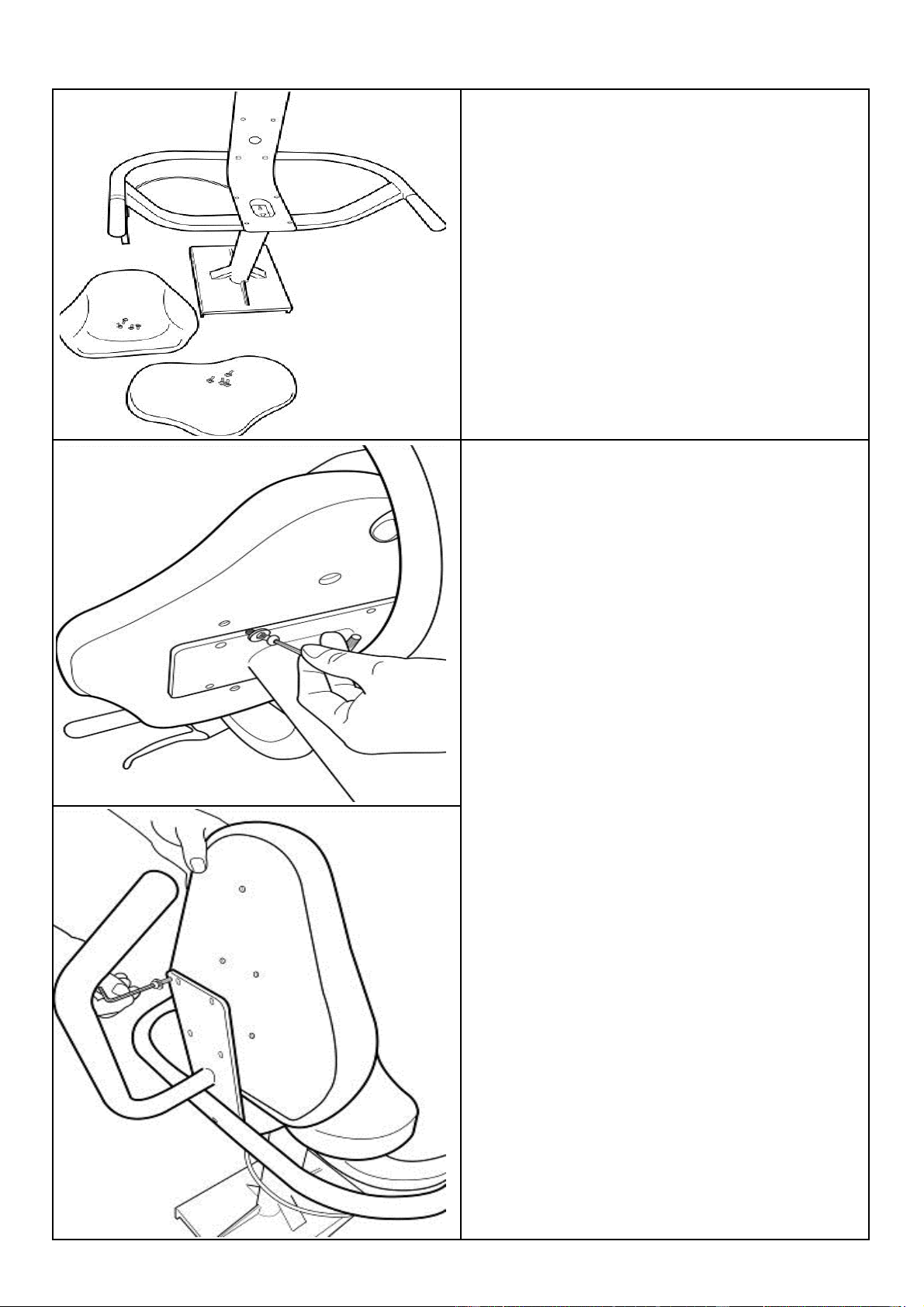
Install Seat Back and Seat
Seat Frame, Seat Back and Seat, 8x
M6x20mm Bolt[4] and 8x M6 Washer
[13]
Install Seat Using 4x M6x20mm Bolt[4]/
Washer[13].
Install Seat Back with as shown with 4x
M6x20mm Bolt[4]/Washer[13]
Once seat pads are installed the assem-
bly will be complete. Check to be sure
that all bolts are securely tightened and
that the cable lever is functioning normal-
ly.
To mount the seat onto the completed
baseplate assembly, align the seat with
the rear of the T-track and depress cable
lever. Tip: Lift entire seat slightly and
slide onto T-track when level to avoid
binding.
Once seat is on T-track, engage the rear
seat stop for safety.
Seat back
Seat
14
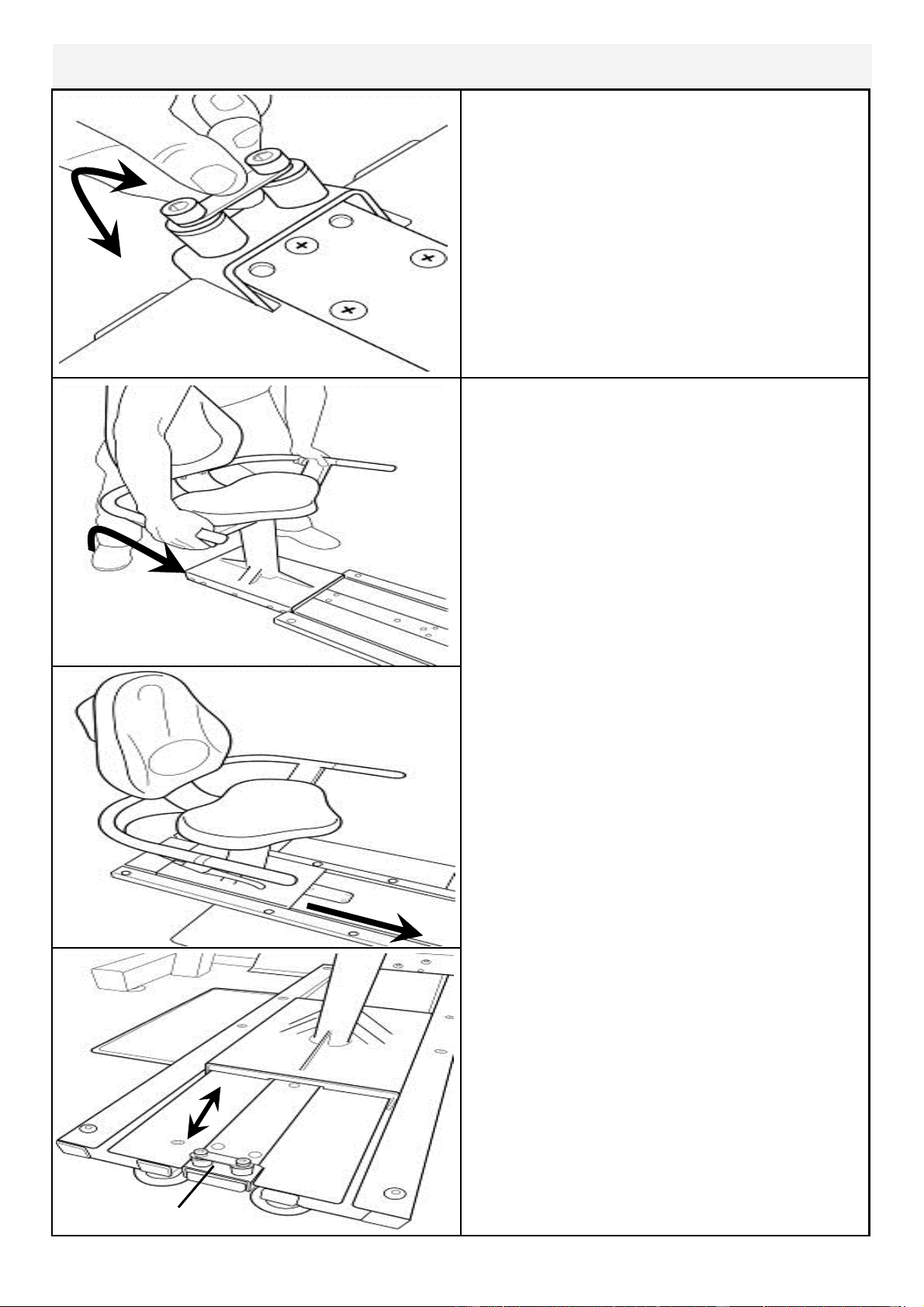
Install Seat onto Baseplate
Seat Stop
Seat Stop: Must be lowered to allow
seat onto Baseplate track.
Must ALWAYS be in the LOCKED
position when seat is occupied on
Baseplate.
Must be lowered to allow seat removal.
To LOCK, raise and locate. To
Seat Installation: Tilt the seat slightly
upward to allow the front rollers to en-
gage the channel. Then, lift the rear lev-
el and, while engaging the Seat Lock Re-
lease Lever, slide the seat onto the
Baseplate as shown.
Usage: The seat has four positions. To
move forward or rearward, depress the
Seat Lock Release Lever and move
freely to whichever position you require.
CAUTION: The Seat Stop Must be in
the LOCKED position whenever the
seat is in use.
To remove the seat: Lift and lower the
Rear Safety lock, depress the Seat Lock
Release Lever and slide the seat rear-
ward.
WARNING: Do not under any circum-
stances attempt to remove/install seat
while occupied.
15
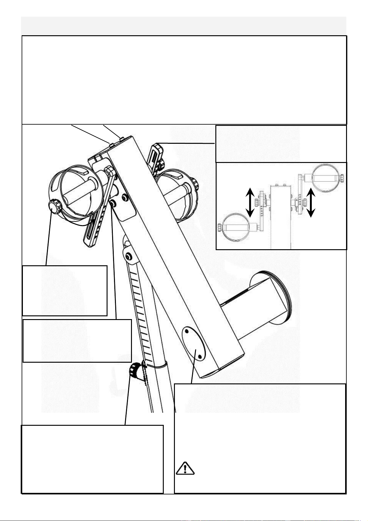
Control Arm
Inspection plate: Open to check chain
tension.
With a screwdriver or other implement,
check tension just behind front sprocket.
Note: A properly adjusted chain will have
3mm-5mm of slack only. See top of page
for adjustment details.
Warning: Do not check chain ten-
sion by Hand!
Crank arm bolts: Loosen
all 8 bolts slightly before
adjusting/tightening chain.
Handgrip: Loosen
knob to adjust han-
dle position from 0-
90 degrees.
Chain tensioning bolts: Allows for tightening the chain or adjustment from side to
side. Make sure when tightening only to adjust the same amount for both bolts,
otherwise the sprocket will be misaligned.
Note: Tightening the right bolt only (turning clockwise) will pull the right side of the
crank assembly toward you, tightening the left will pull the left side toward you. Use
this feature to realign the rear with the front sprocket if needed or when changing to
a new chain.
Adjustment Knob: Loosen to allow
the control arm to travel through 90
degrees of travel. Note the tele-
scoping tube is gas assisted.
Tighten securely when desired
workout position is reached.
E920 Slider Arms: Refer to
following assembly page.
16
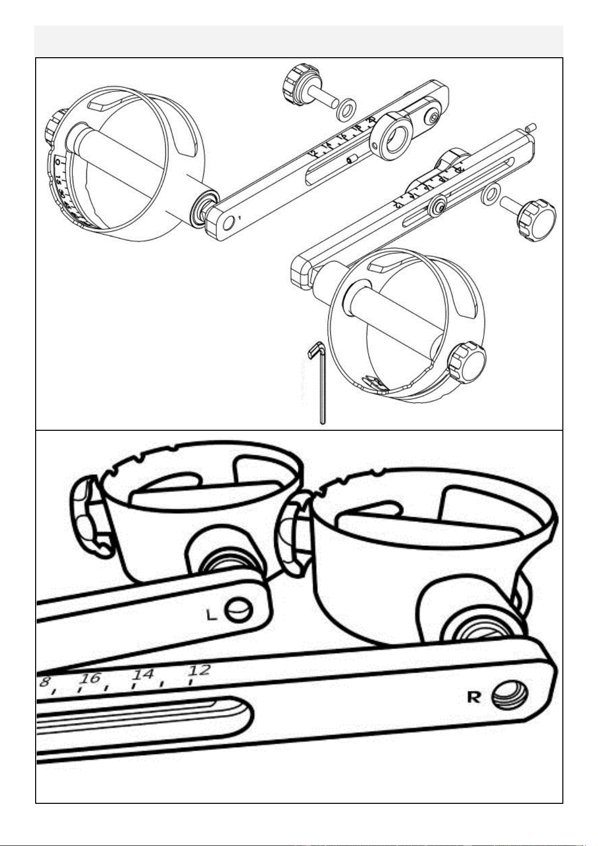
Slider Arm Kit Installation Instructions
Slider Arm Kit includes 1x Slider Arm
Assembly Right (includes right handle),
1x Slider Arm Assembly Left (includes left
handle), 2x Yellow Adjustment Knobs with
Nylon Spacers and 1x 3mm Allen key.
Note: Slider Arms are marked ‘L’ and ‘R’.
Improper installation will result in uneven Slider Arm adjustment.
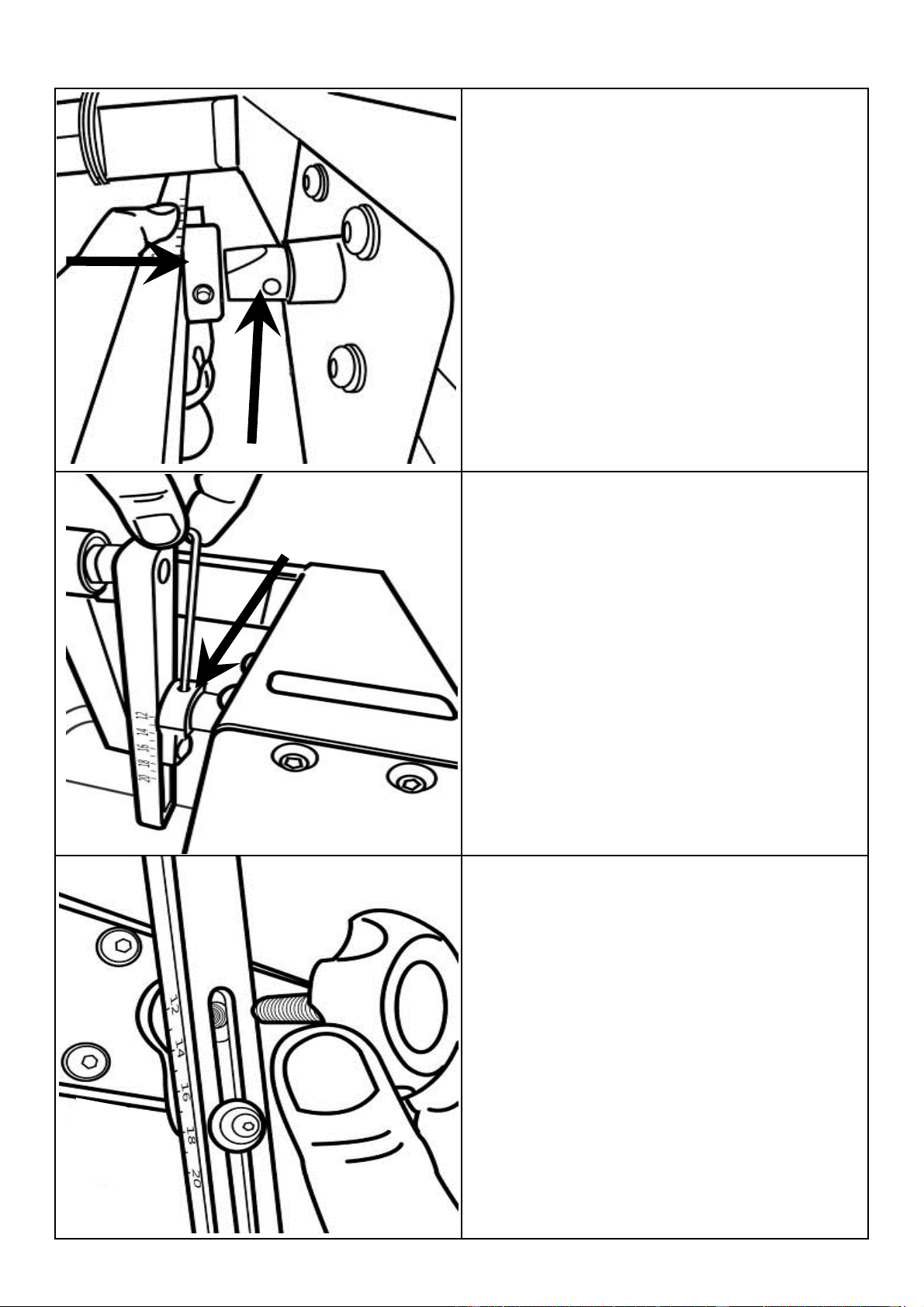
17
Step 1: Mount the left Slider Arm onto
the axle using the yellow indicator hole to
align the slider and axle.
Step 2: Tighten the set screw onto the
axle and into the yellow indicator hole
using the 3mm Allen key.
Step 3: Thread Adjustment Knob onto
axle to secure the assembly.
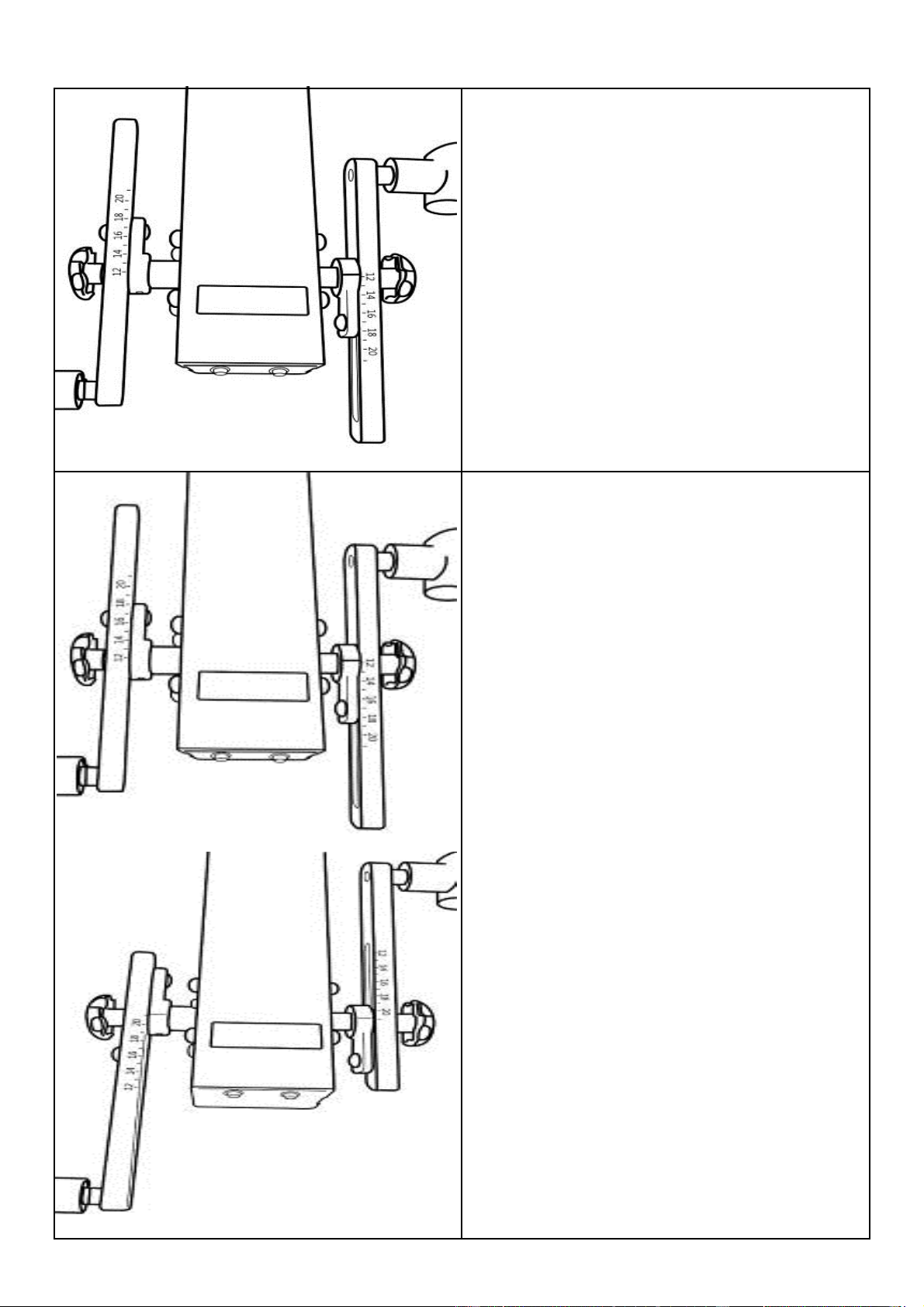
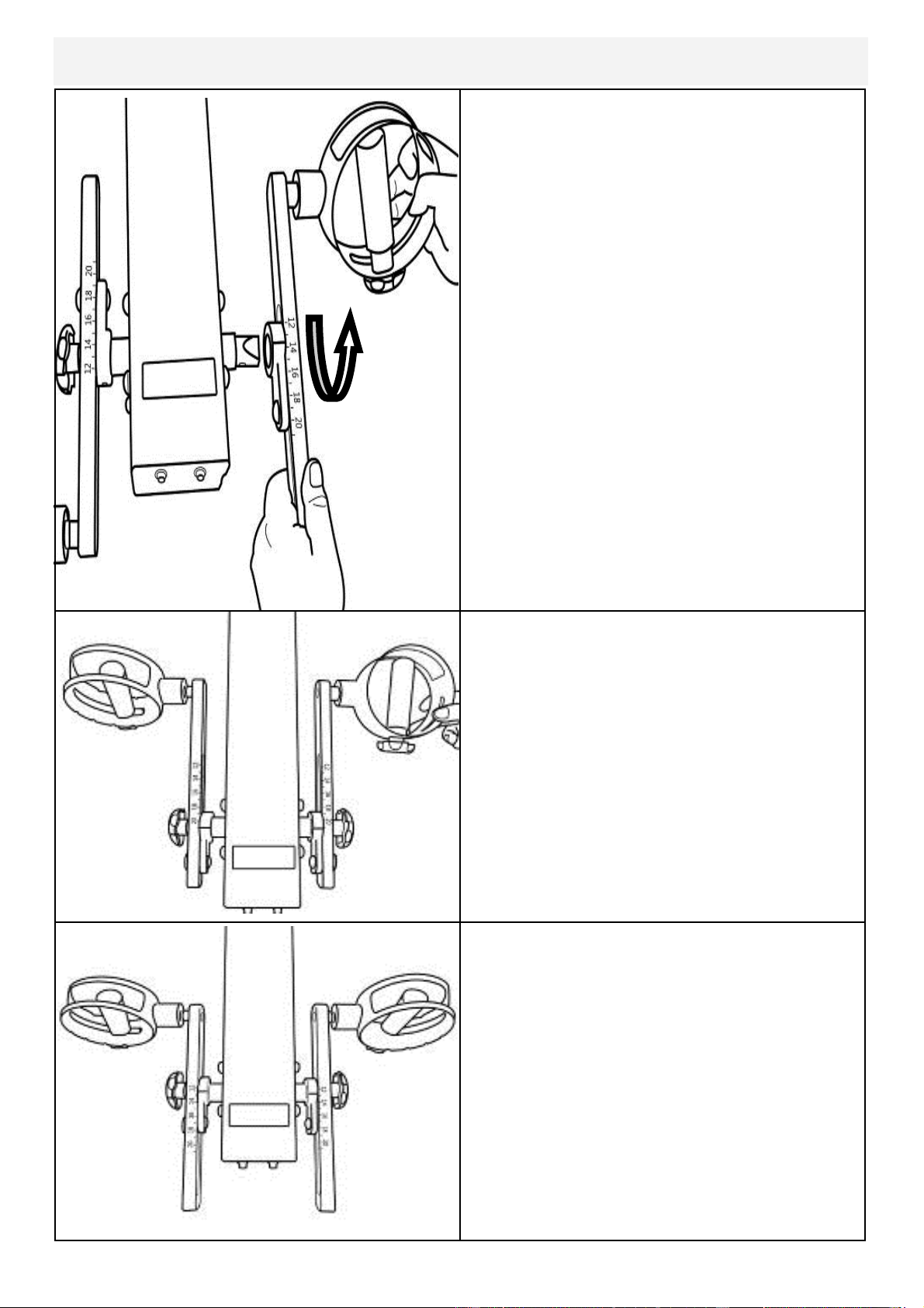
18
The E920 Slider Arm Kit offers the user
an entire range of added resistance set-
tings and the ability to perform addition-
al upper body workouts.
To adjust, simply loosen the Adjustment
Knobs, move Slider Arm to desired
length and secure. Very little tension is
needed.
What do the numbers mean?
The numbers represent the length (in
cm) from the center of the axle to the
center of the handgrip shaft bolt. The
shortest Slider Arm length is 12cm and
the maximum length is 21cm. The
range of adjustment is 9cm.
Step 4: Repeat steps 1-3 to install right
Slider Arm onto axle.
19
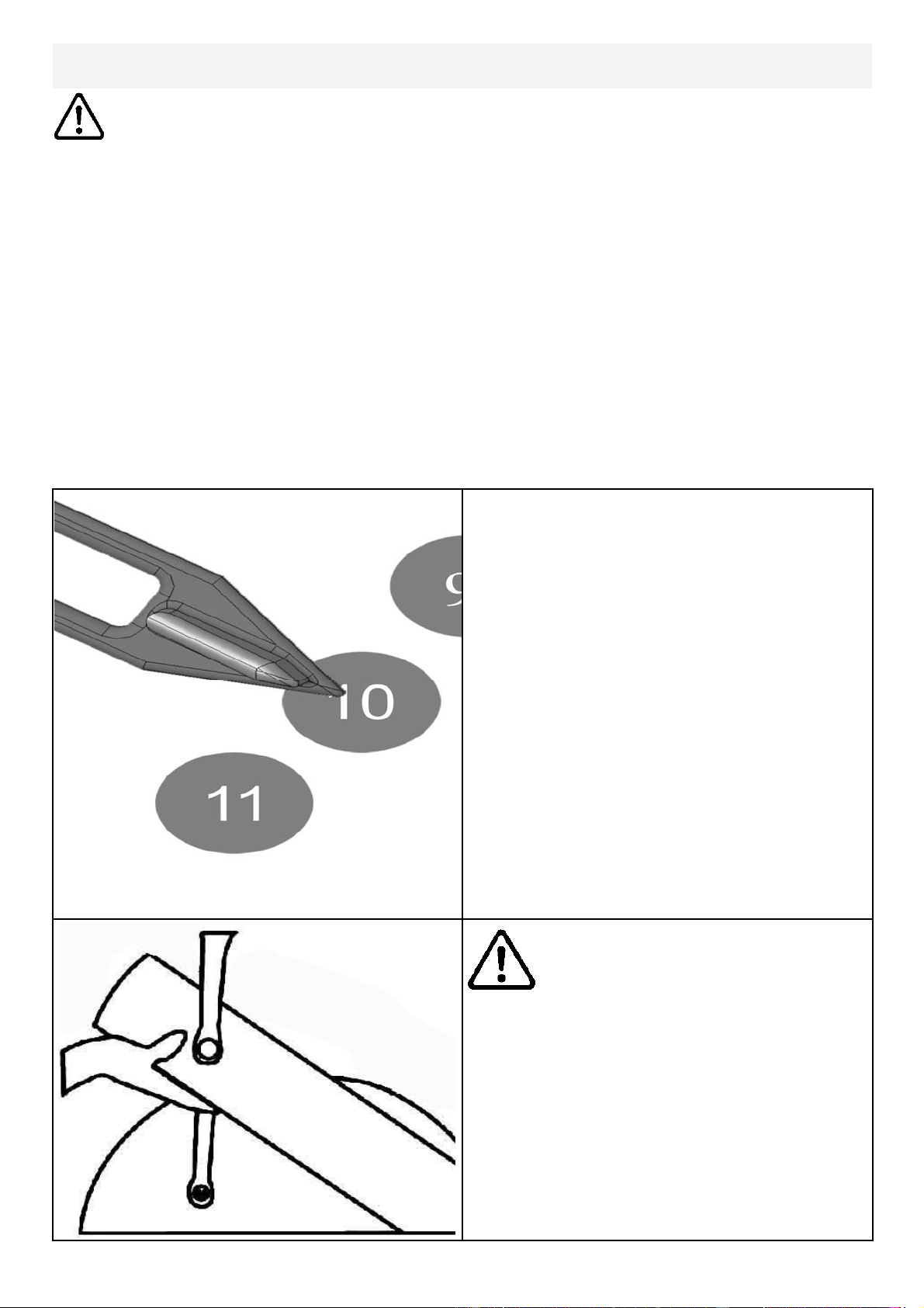
Using Slider Arm
Additional Exercises: Training can now
be achieved with both left and right
Handgrips moving parallel , rather than
in an opposed motion.
Step 1: On the right Slider Arm Assem-
bly, remove the adjustment knob, loosen
set screw and remove Assembly from
axle.
Step 2: As shown below, rotate right
Slider Arm 180 degrees and reinstall on-
to axle. There is an additional screw
locator hole located on opposite side of
axle .
20
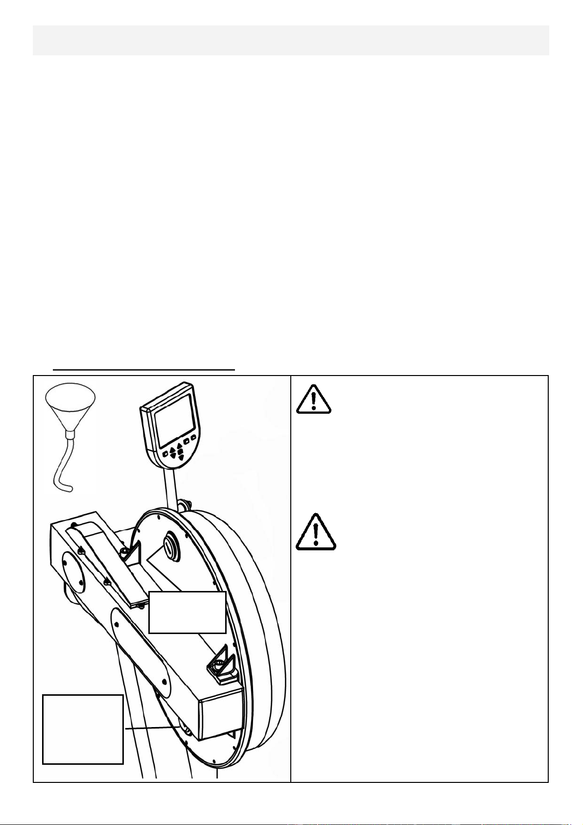
Tank Filling and Water Treatment
Yellow Tank
Plug
Note: A large bucket is required for filling (Not included).
In areas where tap water quality is known to be poor, FDF recommends the use of
distilled water.
Open the tank plug and insert hose into tank (rotating the impeller slightly may be
necessary to allow the hose to pass), move the tank adjuster handle to level 20 and
begin filling. Do not fill the tank higher than the level indicator on the front of the
clear shell. A properly filled tank holds approximately 8 liters of water.
Do not under any circumstances
put fingers into the tank. Use the
end of the hose to move the impel-
ler should the need arise.
Waring
Note: Lower
tank plug is
permanently
sealed.
Use a drop cloth under the tank
when filling the tank to avoid dam-
age floor or carpet
Caution
Water Treatment Procedures:
Add Chlorine tablet
.
Note: The amount of water treatment can vary widely depending on the Rower’s
location and exposure to sunlight. DO NOT, UNDER AN CIRCUMSTANCES USE
ANY TREATMENT TABLETS OTHER THAN THOSE SUPPLIED WITH YOUR
ROWER. Your rower box contents include 4x water treatment tablets, which is suf-
ficient for several years of water treatment. Treat when water becomes discolored
or shows signs of Algae/Bacterial growth. To purchase additional chlorine tabs,
please consult your nearest regional dealer/distributor or check our website
at www.firstdegreefitness.com
21
Long Term Water Treatment and Basic Operation
Long term water treatment:
Water treatment schedules for the E820 will vary according to the fluid
tanks exposure to sunlight but expect 8-12 months near a bright, sunlit
window and 2-4 years for a darker location. At the point of finding the
water slightly green, add a Chlorine tablet. .
Important: Do not fill past the calibration mark as indicated on the tank
level sticker or water spillage may occur. See tank filling and water treat-
ment page for details.
Removing hands before the crank
comes to a complete stop while
training can cause injury. The crank
is direct drive so as to allow both
forward and reverse rotation during
workouts.
Warning:
CAUTION
Resistance:The level of resistance
is determined by the level indicator
located on the front of the tank.
Level one indicates lightest re-
sistance, level twenty represents
heaviest resistance. Allow three to
four seconds after adjusting re-
sistance handle for the correct re-
sistance level to be achieved.
22
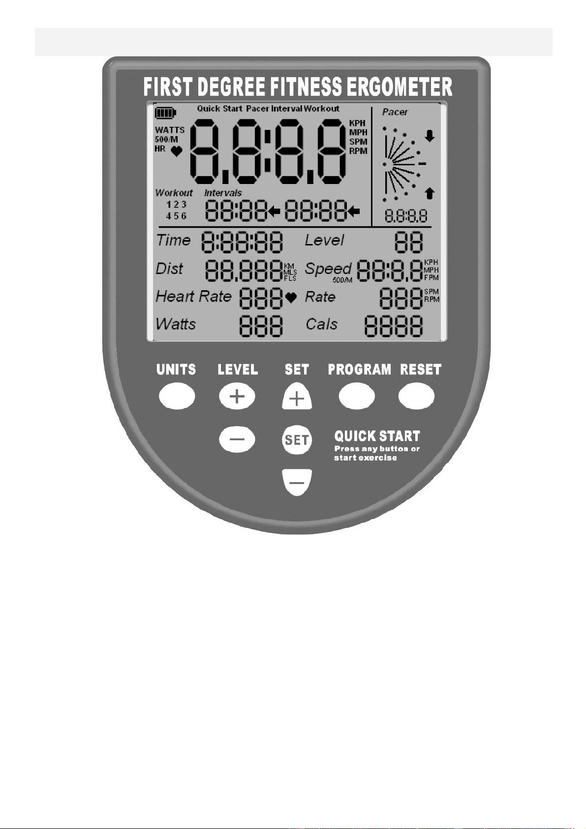
Rower Ergometer
Quick start: Provides instant workout information. Just start training to activate.
You can choose to change UNITS displayed
UNITS: Displays WATTS, SPM, HR, 500/m
LEVEL: Adjustable from 1-20. Match LEVEL number with resistance level on
the Fluid tank.
SET: Changes Time, Distance parameters
PROGRAM: Clears current exercise program
RESET: Clears data
Note: For complete operational instructions, please refer to the computer
manual, which is included with your E-920 Series rower.

23
Description:
The USB connectivity now built in to all new models of FDF Console and IPM allow
you to enhance your exercise experience by connecting to your home PC or Laptop.
Using FDF's own sample applications you can exercise while enjoying your favorite
movies. NetAthlon 2 XF for Rowers lets you race with other Internet connected row-
ers in a Virtual Reality 3D environment or train solo.
Setting up USB connectivity
1.Download and Install the USB Device Driver (CDM2xxxx_Setup.exe for 32 and
64 bit Windows 7/Vista/XP) from the FDF Website.
2.Download and Install the Sample USB Applications from the FDF Website
(www.firstdegreefitness.com).
Download and Install NetAthlon 2 XF for Rowers from
http://www.webracing.org/downloads.htm
Connecngyourconsole
‐TheUSBConnectorislocatedonaflyingleadattherearoftheIPM,alongwiththeSensor
andHeartRateMonitorConnectors.
‐ConnecttoaLaptoporPCusingastandardUSBcable,youmayneedtowaitwhileWin‐
dowsstartstheUSBDeviceDriver.
Using the First Degree Fitness USB Interface
Note: Please refer to computer manual where applicable or for further
information refer to our website at www.firstdegreefitness.com

24
Item Timeframe Instructions Notes
Seat and
Frame.
Weekly. Wipe down weekly with lint
free cloth or more often with
heavy club use.
PK belt tension. Monthly. Check monthly for signs of
slippage. Refer to “Tank
belt adjustment” page.
Tank and water
treatment.
12 months to 4
years.
Follow instructions as speci-
fied in the “Water Treat-
ment” section of this manu-
al.
Chain drive. Check every 100
hours for correct ten-
sion.
Open the inspection plate
and check tension using a
screwdriver or other tool.
Tighten as required and re-
fer to “E920 Control Arm”
page for instructions.
E920 HandGrip
Assembly.
Check weekly using
Multi-Tool(supplied)
to ensure HandGrip
Assembly is securely
tightened into Crank
Arm.
The HandGrips should be
checked on a regular basis.
Continued use of a loose
HandGrip can cause
damage to the Crank Arm
threads, necessitating re-
placement.
Maintenance Chart

25
Fault
Probable
Cause
Solution
Tank internal surfaces
show green deposit.
Rower is in direct
sunlight or has not
had water treat-
ment.
Add water treatment or change tank wa-
ter as directed in the water treatment sec-
tion of this manual.
Consider using dis-
tilled water to refill tank.
Knocking noise from
inside the control arm
while training, especial-
ly when changing direc-
tions.
Chain requires
tightening or ad-
justment.
Open inspection plate located on front of
control arm and check tension using a
screwdriver or other tool. Use the chain
tensioning bolts located at the rear of the
control arm to tighten or adjust as need-
ed. The chain should have approx 3mm
of slack when properly adjusted. See P.6
for details.
HandGrips slip during
hard training.
PK tank belt re-
quires tightening.
Remove large inspection plate next to the
tank, insert a long tool to push the rear
end cap out from the inside, exposing the
tank belt tensioning bolt. Loosen tank
bolts slightly. Remove upper rubber belt
cover to expose the PK belt. Tighten the
tank tensioning bolt until the belt is too
tight to be twisted from side to side more
than 45 degrees by hand. See P.15 for
details
HandGrip is loose
(either left or right) and
cannot be retightened.
Crank arm threads
are stripped.
Contact service center for replacement.
Then check weekly as recommended.
Computer screen illumi-
nates, but does not reg-
ister when rowing.
Loose or failed
connection. Sensor
gap too wide (see
erratic computer
display).
Check that the computer lead is connect-
ed properly. If connected properly, check
sensor gap. Open main inspection cover
and check behind magnetic ring. Sensor
head to ring gap should be no more than
2.5mm.
The E920 computer
does not illuminate af-
ter battery installation.
Batteries installed
incorrectly or need
replacing.
Reinstall batteries in correct position and
try again. If the LCD screen fails to illumi-
nate, try rotating the batteries slightly in
the computer. If this fails, contact your
local service center.
The E920 computer
display is erratic/slow
while displaying RPM
and WATTS
Gap between sen-
sor and magnetic
ring is too wide.
Once inspection plate is removed, check
behind magnetic ring and inspect sensor
head/ring distance. Gap should be
2.5mm wide or less. Check Magnetic
ring for wobble.
Troubleshooting
26
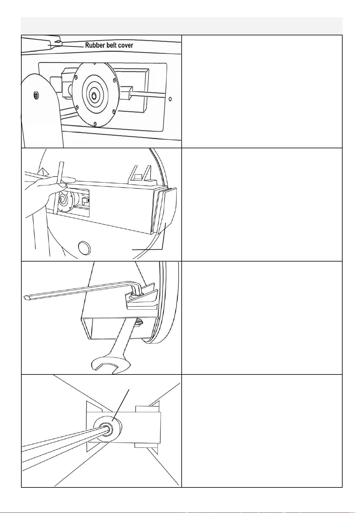
Tank tensioning
Tank Belt Adjustment
End Cap
Remove large metal inspection plate as
shown above right.
Using a long tool, push out the rear end
cap as pictured right. This will give you
access to the tank tensioning bolt (shown
bottom right).
Loosen both the front and rear tank bolts
as shown below. Remove front rubber
belt cover.
Using a 6mm Allen key, tighten the belt
using the tank tensioning bolt until the
belt no longer slips during hard rowing.
Tip: Twist the belt by hand to gauge
tightness. Correct tension should be ob-
tained when no longer able to twist more
than 45 degrees.
Note: Do not over tighten tank bolts.

27
FLUID CYCLE XT & UPPER BODY ERGO (UB-E920)
INTERNATIONAL WARRANTY – FULL COMMERCIAL USE
This product is designed and constructed for use in any Health Club / Fitness Studio application
First Degree Fitness Limited warrants that the Fluid Upper Body Ergometer (model UB-E920), purchased from an
authorised agent and in its undamaged original packaging, is free from defects in materials and workmanship. First
Degree Fitness Limited or its agent will, at their discretion, repair or replace parts that become defective within the
warranty period, subject to the specific inclusions and exclusions below.
Metal Frame – 10 Year Limited Warranty
First Degree Fitness will repair or replace the metal Main Frame should it fail due to any defect in materials or work-
manship within 10 years of the original purchase. Warranty does not apply to frame coating.
Polycarbonate Tank & Seals – 3 Year Limited Warranty
First Degree Fitness will repair or replace the polycarbonate tank or seals should they fail due to any defect in materi-
als or workmanship within 3 years of the original purchase.
Mechanical Components (of a non-wearing nature) – 2 Year Limited Warranty
First Degree Fitness will repair or replace any mechanical component should it fail due to any defect in materials or
workmanship within 2 years of the original purchase.
All Other Components (of a wearing nature) – 1 Year Limited Warranty
First Degree Fitness will repair or replace any component should it fail due to any defect in materials or workmanship
within 1 year of the original purchase.
Specific Inclusions
Pedals & toe straps
Hand grip assemblies
Seat
All rubber components
Computer & speed sensor (excluding replaceable batteries)
All drive belts & chains
Crank arms
All pulleys, rollers & bearings
General Exclusions
Damage to the finish of any part of the machine
Damage due to neglect, abuse, incorrect assembly or use of the machine
Any charges for freight or customs clearance associated with the return or dispatch of parts
Any damage to or loss of goods during transport of any kind
Any labour cost associated with a warranty claim
General Conditions
The serial number of the machine must be correctly registered with First Degree Fitness Limited or one of its ap-
pointed distributors
First Degree Fitness Limited reserve the right to examine any part where replacement is claimed under warranty
Warranty commences at time of sale but no later than six (6) months from date of original shipment
Warranty period applies only to the original purchaser from the date of purchase and is not transferable
The product must be returned to your place of purchase in original packaging with transportation, insurance and
associated charges paid for by you and risk of loss or damage assumed by you
First Degree Fitness makes no other warranties except as stated here and expressly disclaims all warranties not
stated in this warranty. Neither First Degree Fitness nor its associates shall be responsible for incidental or con-
sequential damages
Manufacturer's warranty automatically commences upon sale of the product to end user or upon the expiration of
one (1) year from month of manufacture, whichever occurs first