Loading ...
Loading ...
Loading ...
• 7 •
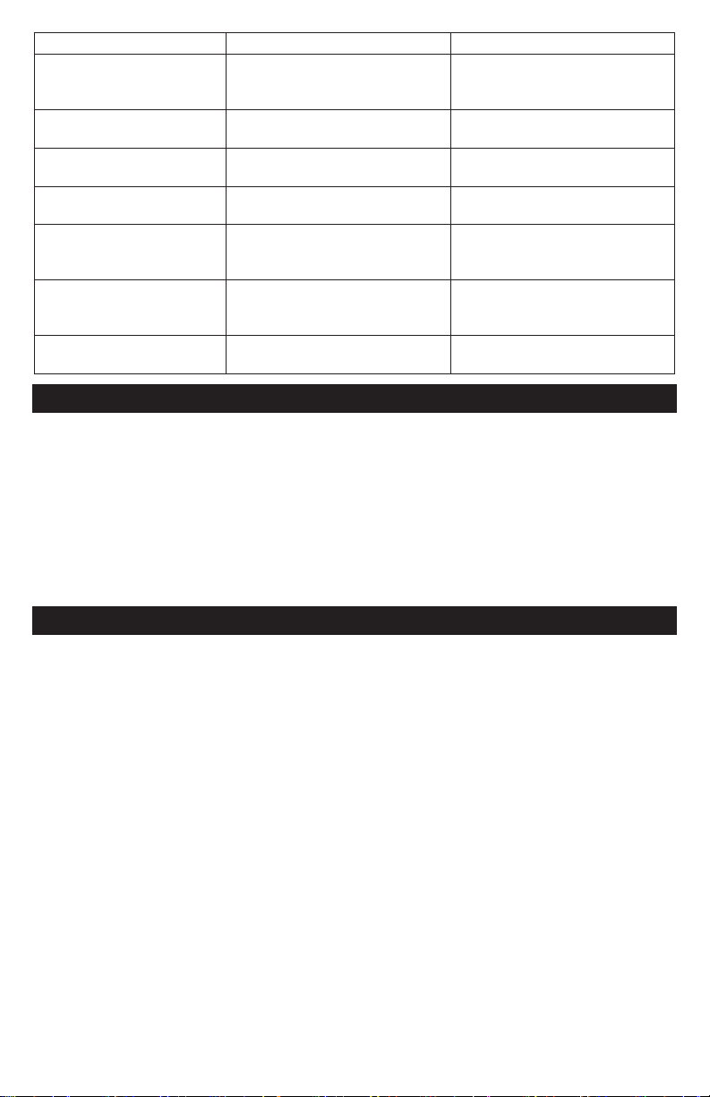
PROBLEM POSSIBLE CAUSE SOLUTION
Display shows HIGH
CHARGING VOLTS
WHEN AT IDLE.
The alternator output exceeds
the normal limits of a functioning
regulator.
Check the manufacturer
specications for the correct limit.
Display shows RIPPLE
DETECTED NORMAL.
The diodes are functioning
properly in alternator/stator.
No problem is detected.
Display shows NO
RIPPLE DETECT.
The diodes are functioning
properly.
No problem is detected.
Display shows RIPPLE
DETECTED HIGH.
Diodes are bad. Have the alternator checked.
Display shows ALT. LOAD
VOLTS HIGH.
The alternator output voltage
exceeds the normal limits of a
functioning regulator.
Have the alternator checked.
Display shows ALT. LOAD
VOLTS LOW.
The alternator output voltage
is low.
Have the alternator checked.
Display shows ALT. LOAD
VOLTS NORMAL.
The alternator output voltage is
normal.
No problem is detected.
BEFORE RETURNING FOR REPAIRS
For information about troubleshooting,
contact customer service for assistance:
www.batterychargers.com
or call 1-800-621-5485, Monday-Friday 7:00am to 5:00pm CST
For REPAIR OR RETURN, contact Customer Service at 1-800-621-5485. DO NOT SHIP
UNIT until you receive a RETURN MERCHANDISE AUTHORIZATION (RMA) number
from Customer Service at Schumacher Electric Corporation.
REPLACEMENT PARTS
Output Leads .............................................................................................. 2299001824
Battery Cover .............................................................................................. 3799006010
Paper Cover ................................................................................................ 3799006020
Carrying Case ............................................................................................. 2299001986
Paper Roll (1) .............................................................................................. 4999000106
Cable Cover ................................................................................................ 3799006724
Replacing The Output Leads
1. Remove the screw in the backside
bottom cover of the battery tester, and
then remove the cover.
2. Disconnect the old cable connectors
and insert the connectors of the new
cable into the corresponding same color
sockets (yellow connector into yellow
socket; red connector into red socket;
white connector into white socket; black
connector into black socket).
IMPORTANT: There is a small rib on the
tester case, place the rst slot of the
rubber strain relief attached to the cable
over this rib. There is also a rib on the
cover you removed, make sure that the
rib is in the rst slot of the strain relief
when you replace the cover. Replace the
cover and tighten the screw. Do not
over-tighten.
Loading ...
Loading ...
Loading ...