_RINTED IN U S A
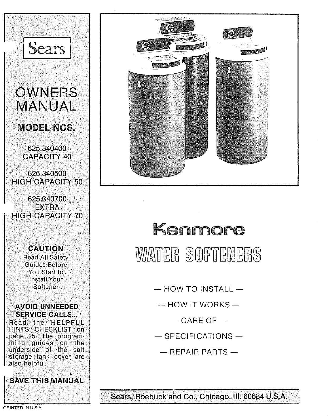
K@n ore
-- HOW TO INSTALL-
- HOW IT WORKS --
-- CARE OF --
-- SPECIFICATIONS --
-- REPAIR PARTS --
OF CONTENTS
PAGE NO.
PAGE NO.
Safety Guides ................................... 3
Before You Install ......................... 3-5
Tools and Materials Needed .................. 4
Plans to Install Your Softener ............... 5-8
Sweat Soldering Tips ........................... 7
Step by Step Guides to lnstall Softener ._ 9-14
Setting the Timer ,...................... 14
How Your Softener Works ............... 15-17
"Fine-Tuning" Your Softener ............. 18-22
Care of Your Softener ...................... 23-25
Dimensions and Specifications ................... 26
Repair Parts .............................. 27-31
I WARRANTY
SEARS RESIDENTIAL AUTOMATIC WATER SOFTENER
FULL ONE YEAR WARRANTY ON WATER SOFTENER
For one year from the date of purchase, when this water softener is installed and
maintained in accordance with our instructions, Sears will repair, free of charg.e, defects
in material or workmanship in this water softener
FULL TEN YEAR WARRANTY AGAINST LEAKS
For ten years from the date of purchase, Sears will furnish and instal! a new current
model water softener tank or salt storage drum, free of charge, if either the tank or drum
develop a leak
TO OBTAIN WARRANTY SERVICE, SIMPLY CONTACT THE NEAREST
SEARS SERVICE CENTER THROUGHOUT THE UNITED STATES. THIS WAR-
RANTY APPLIES ONLY WHILE THIS PRODUCT IS IN USE IN THE UNITED
STATE&
This warranty gives you specific legal rights, and you may have other rights
which vary from state to state.
Sears, Roebuck and Co., Dept. 698/731A, Sears Tower, Chicago, IL 60684
If you want your water softener professionally installed, talk to your Sears Salesperson who will ar-
range a prompt, quality installation by Sears Authorized Installers.
SEARS INSTALLATION POLICY
All installation labor arranged by Sears shall be
performed in a neat, workmanlike manner in
accordance with generally accepted trade prac-
tices Further,all installations shall comply withall
local laws, codes, regulations and ordinances
Customer shall also be protected, during installa*
tion, by insurance relating to Property Damage,
Workman's Compensation and Public Liability
SEARS INSTALLATION WARRANTY
In addition to any warranty extended to you on
the Sears merchandise involved, which warran-
ty becomes effective the date the merchandise
is installed, should the workmanship of any
Sears arranged irrstallation prove faulty within
one year, Sears will, upon notice from you,
cause such faults to be corrected at no addi-
tional cost to you.
2
Read all steps, guides and rules carefully
before installing and using your new water
softener. Follow all steps exactly to correctly
install. Failure to follow them could cause
personal injury or property damage. Read-
ing this book will also help you to get all of the
benefits from your water softener.
A Your water softener will remove hardness
minerals and "clear water" iron from water,
up to the limits shown on page 26. It will not
remove other types of iron, acids, tastes and
odors, etc° It will not purify polluted water or
make it safe to drink.
When you see this sign in the book,
is not followed exactly.
A Check with your local public works depart-
ment for plumbing, electric and sanitation
codes. You must follow their guides as you
install your softener.
A Protect the softener and piping from freez-
ing. Damage from freezing voids the softener
warranty.
,_ Be sure the electric outlet for the softener
is grounded the right way to protect the
user from injury or possibly fatal shock.
A THIS SOFTENER WORKS ON 24 VOLTS
ONLY. BE SURE TO USE THE TRANS-
FORMER INCLUDED, AND PLUG IT INTO A
120V OUTLET.
A something could be damaged, or someone hurt, if the guide
HELPFUL INFORMATION
If you know little about plumbing skills, we sug-
gest you get a book on the subject There are
many good books for do-it-yourselfers on the
basics of plumbing. You can get a low cost book
from Sears Plumbing and Heating departments
that will help you Some basic sweat soldering
tips are on page 7 of this manual
WATER SYSTEM TESTS
HAS YOUR WATER SUPPLY HAD A
CHEMICAL ANALYSIS? Sears has many kinds
of water treating units (see page 4) to correct
different water problems. To know the kind
and size of unit you need, you must first know
what elements are in your house water supply.
A chemical analysis shows the type and
amounts of elements in water. If your water
needs analysis, call or write your nearest
Sears store for help.
CHECK YOUR WATER PRESSURE-- For your
softener to work right, a water pressure of no
lower than 20 pounds per square inch (psi) is
needed in the house water pipes The highest
• pressure allowed in the water pipes is 120 psi If
pressure is over 120 psi, buy and install a pres-
sure reducing valve in the water inlet pipe to the
softener. NOTE: If water pressure during the
day is 100 psi or more, pressure during the
night may go over 120 psi.
If you have a well water system, look at the
pressure gauge to find the water pressure. Call
your local water department if you have city
water. They will tell you what the water
pressure is where you live.
CHECK YOUR WATER FLOW RATE - A water
flow of at least 3 gallons per minute is needed.
A lower flow will keep your softener from work-
ing as well as it should° To make an easy
check of your flow rate, do the following. You
will need a 1 gallon container (can, jar, pail,
etc.).
.
2_
Fully open 2 cold water faucets close to the
point water enters the house.
With both faucets open, fill the gallon con-
tainer at 1 faucet while looking at awatch or
clock to see how many seconds it takes.
3. Empty the container and go the second
faucet (be sure BOTH faucets are still on).
Fill the gallon container at the second
faucet and see how many seconds it takes.
4. Turn off both faucets. Now add the number
of seconds it took to fill the container at
.
both faucets.
A total of 90 seconds, or less, means the
system flow rate is good.
FACTS AND FIGURES TO KEEP
Fill in the blanks below and keep this book in a
safe place so you always have these facts
Water Softener Model Not
Serial Number
Date Installed
Water Hardness
Iron Content
*pH
Water Pressure
Grains Per Gallon
Parts Per Million
Taste And/Or Odor
__ Pounds/Square Inch
Water Flow Rate Gallons Per Minute
_-Get from the rating decal on the softener.
*The acidity or alkalinity measure of water
WHERE TO PUT THE SOFTENER
Think of the following points as you choose a
place to put your softener (See Fig 1)
• Place as close as possible to the pressure
tank (well water) or water meter (city water).
e Place as close as possible to a water drain
such as a floor cfrain, laundry tub, sump or
standpipe.
Ao Connect to the house main water pipe BEFORE
THE WATER HEATER Temperature of water
going through the softener must not be more
than 120 F (49 C)
O
Ao
&
,&
A
Keep your outside faucets on hard water to
save soft water and salt.
DO NOT install in a place where the
softener could freeze. Freeze damage
voids the warranty by Sears, Roebuck and
Co. (See page 24..)
• A 120V electric outlet, to plug the
transformer into, is needed within 10
feet of the softener(the softener has a 10
foot power cable). Be sure the outlet and
transformer are in an inside place, to pro-
tect from wet weather.
• Keep the softener out of direct sunlight. The
sun's heat can melt plastic parts.
• Put the softener in a place water damage is
least likely to occur if it develops a leak Sears
or the manufacturer will not repair or pay for
water damage
TOOLS, PIPE, FITTINGS
AND OTHER MATERIALS YOU WILL NEED
To know what tools and materials you will need,
you must first decide how to run in and out pipes
to the softener Look at your house main water
pipe at the point you will con nect the softener Is the
pipe soldered copper, glued plastic, or threaded
galvanized or brass? What is the pipe size?
Now look at the common plans for in and out
piping on pages 6 and 8. Select the drawing
best for you and use it as a guide to plan what
materials you will need_ As you plan your in
and out piping, keep in mind the following
check list. Then get all the materials you will
need.
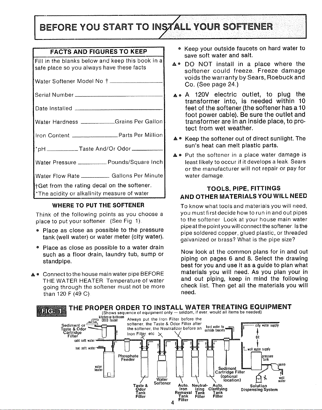
THE PROPER ORDER TO INSTALL WATER TREATING EQUIPMENT
(Shows sequence of equipment on_y -- seldom, if ever would all items be needed)
_ki_ru_'oem-- ---_____ _ Always put the Iron Filter before the
Sediment" or _ _ so ene he Tas e & Odor. Filter aftern ha_dwaterto _ city............watersupply
Taste & Odor_ _ the softener, the Neutralizer before a ..... _ _---- c_cyw_e_supply
Cartridge I I li _/ 8glSl_e fa_ce[s Ill II A
_.. _ _ Ill Iron F ter etc _x \/ II II T
U L.°,00,u00,,,-- r. .
- = I I II g i 1 --pu_,
=,,I I1[-I | [ |Sod,me.tL4__J'TX'
..... -J -, "terZ,.
/ Softener \ _ location) _ _ w'[tu
Taste & Auto. Neutral- Auto. Solution
Odor Iron Izlng Clarifying Dispensing System
Tank Removal Tank Tank
Filter Tank Filter Filter
Filter
4
I BEFORE YOU START 3=0
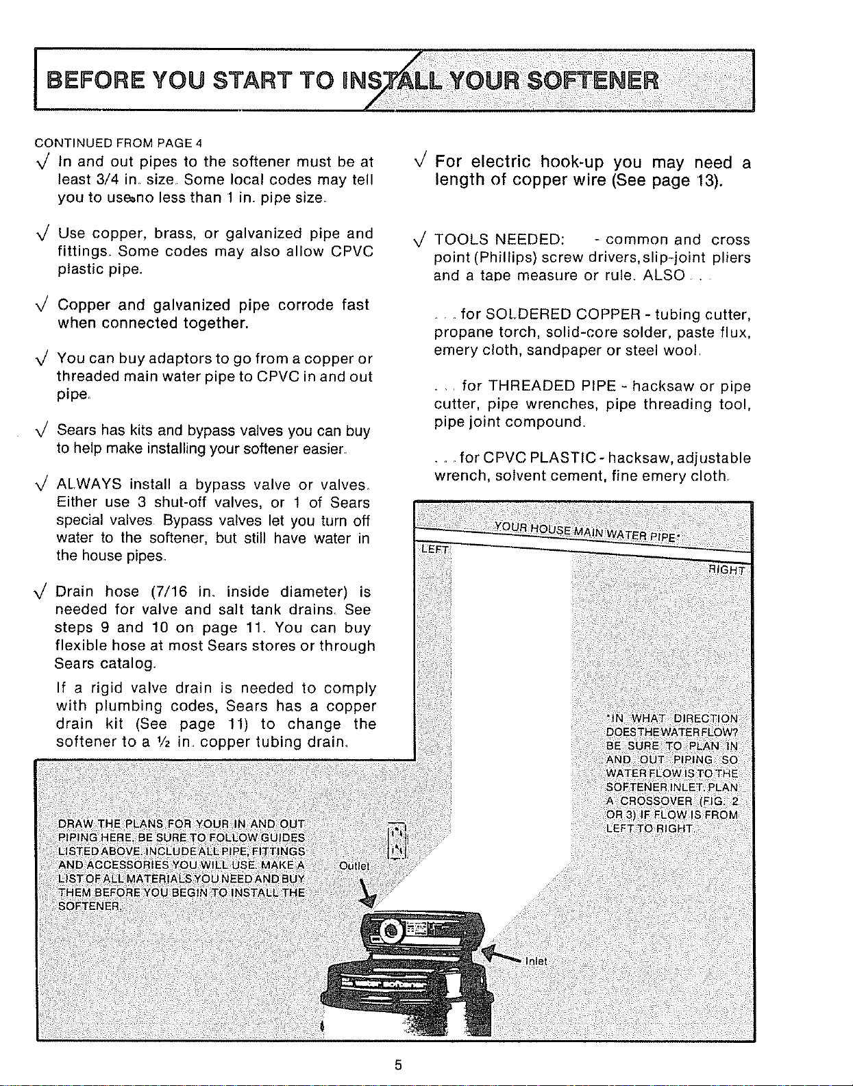
CONTINUED FROM PAGE 4
X/ In and out pipes to the softener must be at
least 3/4 in size Some local codes may tell
you to use_no less than 1 in. pipe size
_/ Use copper, brass, or galvanized pipe and
fittings. Some codes may also allow CPVC
plastic pipe_
_/ Copper and galvanized pipe corrode fast
when connected together.
x/ You can buy adaptors to go from a copper or
threaded main water pipe to CPVC in and out
pipe.
x/ Sears has kits and bypass valves you can buy
to help make installing your softener easier
x/ ALWAYS install a bypass valve or valves.
Either use 3 shut-off valves, or 1 of Sears
special valves Bypass valves let you turn off
water to the softener, but still have water in
the house pipes.
x/ Drain hose (7/16 in. inside diameter) is
needed for valve and salt tank drains. See
steps 9 and 10 on page 11. You can buy
flexible hose at most Sears stores or through
Sears catalog.
If a rigid valve drain is needed to comply
with plumbing codes, Sears has a copper
drain kit (See page 11) to change the
softener to a 1/2 in copper tubing drain.
,/
For electric hook-up you may need a
length of copper wire (See page 13).
TOOLS NEEDED: -common and cross
point (Phillips) screw drivers,slip-joint pliers
and a tape measure or rule. ALSO .
for SOLDERED COPPER- tubing cutter,
propane torch, solid-core solder, paste flux,
emery cloth, sandpaper or steel wool
for THREADED PIPE - hacksaw or pipe
cutter, pipe wrenches, pipe threading tool,
pipe joint compound.
• _. for CPVC PLASTIC- hacksaw, adjustable
wrench, solvent cement, fine emery cloth

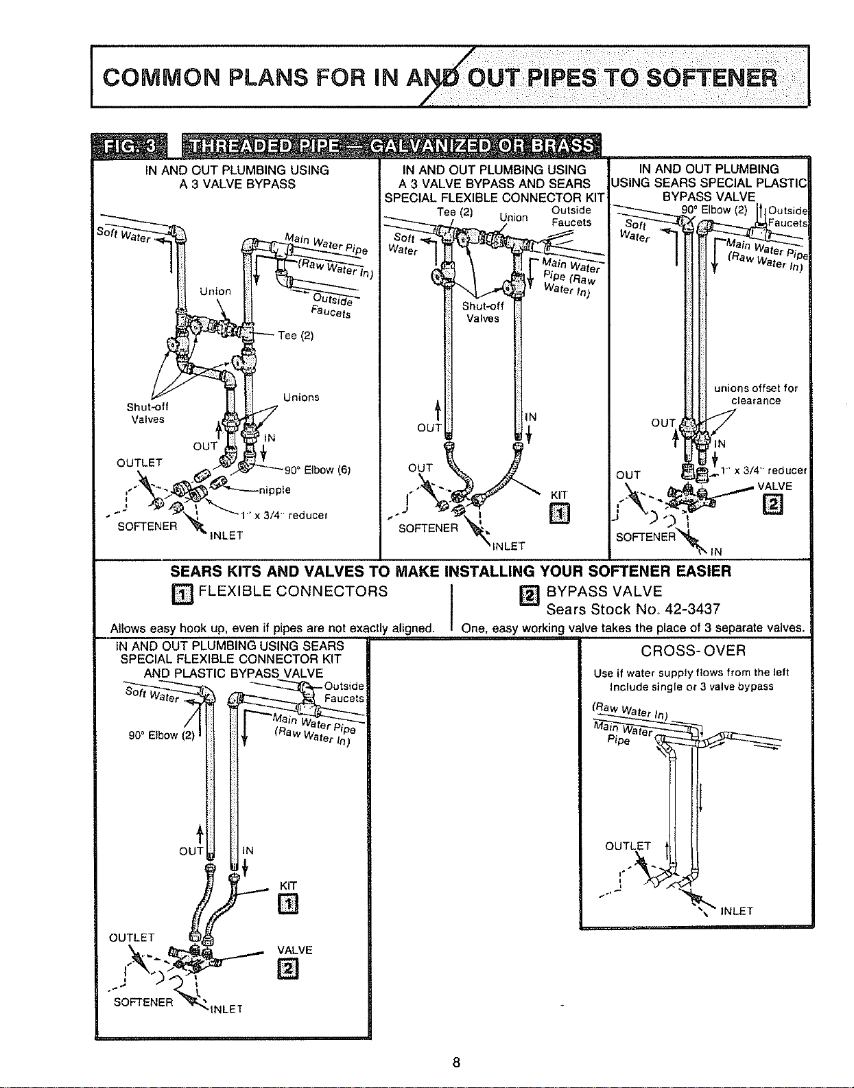
IN AND OUT PLUMBING USING
A 3 VALVE BYPASS
Tee (2) Outside
I
, Faucet
Water 1
_ _ .... Waterln)
i
i
ili i!_i
OUT
IN
f
Outlet )._^;_ _.--90 ° Elbow (4)
..J_ ,_:___°u,
_nasket fwith
SOFTENER _, = softener
_lnlet
IN AND OUT PLUMBING USING
A 3 VALVE BYPASS AND SEARS
SPECIAL FLEXIBLE CONNECTOR KIT
90_ Elbow (2) Outside Faucets
_ (F{aw er Pipe
a_er In)
[
! ./.Tee (2)
i i'_ _ Shut-_f f Valves
OU]_ _ IT
our\
IN AND OUT PLUMBING
USING SEARS SPECIAL PLASTIC
BYPASS VALVE
sof_ _ ,-____2o°E_bow(2)
I I|1 I ,.alnw_
/ Itl _ (Raw'lva'_rt'lpe
-
i tlIN Outside
Faucet
OU
S.aight---._I_J_
Connector (2) ,_l_..fnut -_ included
r_j_]- _ "_ with
FL.,_ tuee _ softener
out_et ._u _as,et
SOFTENER Inlet
SEARS KITS AND VALVES TO
_ FLEXIBLE CONNECTORS
Allows easy hook up even if pipes
are not exactly aligned.
IN AND OUT PLUMBING
USING SEARS SPECIAL FLEXIBLE
CONNECTOR KIT AND PLASTIC
BYPASS VALVE ,cote
90° Elbow (2) ts'_&e_:au
o4U;"
Out,or _'_) VA,VE
%let []
MAKE INSTALLING YOUR SOFTENER EASIER
BYPASS VALVE (Plastic) _ BYPASS VALVE (Brass)
Sears Stock No. 42-3437 Sears Stock No, 42-3436
One, easy working valve takes the place of 3 separate valves,
IN AND OUT PLUMBING
USING SEARS SPECIAL BRASS
BYPASS VALVE
90° Elbow (4) Oe ts'_6e
/ ,_aoGetS
: r Pipe
I } (Raw Water In)
OUT ; IN
VALVE
i!
OUT _tN
Plumb to softener
using fittings shown
in 3 valve bypass
CROSS-OVER
Use if water supply flows from the left
Include single or 3 valve bypass
Main Water Pipe
1
Outlet
""i['OFT _E_E_inlet
]
SWEAT SOLDERING TIPS
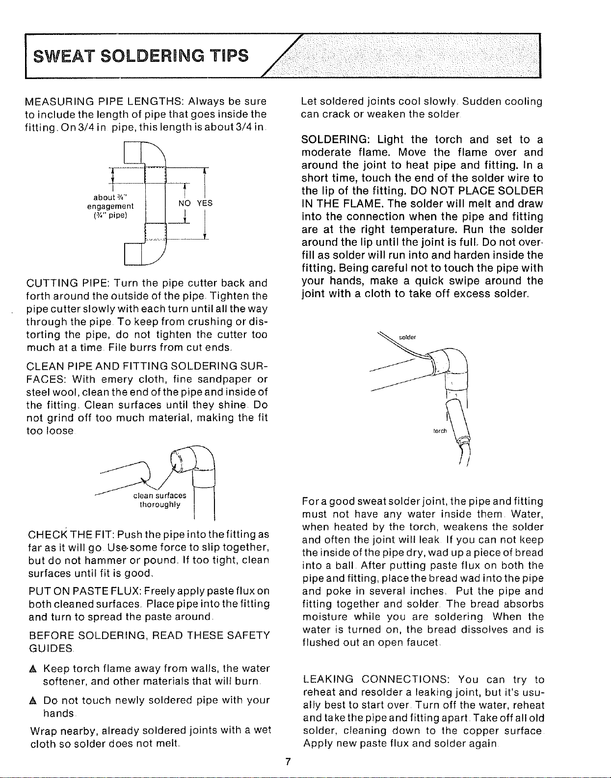
MEASURING PIPE LENGTHS: Always be sure
to include the length of pipe that goes inside the
fitting, On 3/4 in pipe, this length is about 3/4 in
about 3/_.,
engagement NO YES
(J/.'"pipe)
CUTTING PIPE: Turn the pipe cutter back and
forth around the outside of the pipe Tighten the
pipe cutter slowly with each turn until all the way
through the pipe To keep from crushing or dis-
torting the pipe, do not tighten the cutter too
much atatime File burrs from cutends_
CLEAN PIPE AND FITTING SOLDERING SUR-
FACES: With emery cloth, fine sandpaper or
steel wool, clean the end of the pipe and inside of
the fitting Clean surfaces until they shine Do
not grind off too much material, making the fit
too loose
clean surfaces
thoroughly
CHECK THE FIT: Push the pipeintothefitting as
far as it will go Use-some force to slip together,
but do not hammer or pound If too tight, clean
surfaces until fit is good_
PUT ON PASTE FLUX: Freely apply paste flux on
both cleaned surfaces Place pipe into the fitting
and turn to spread the paste around,
BEFORE SOLDERING, READ THESE SAFETY
GUIDES
A Keep torch flame away from walls, the water
softener, and other materials that will burn
A Do not touch newly soldered pipe with your
hands
Wrap nearby, already soldered joints with a wet
cloth so solder does not melt
Let soldered joints cool slowly Sudden cooling
can crack or weaken the solder
SOLDERING: Light the torch and set to a
moderate flame. Move the flame over and
around the joint to heat pipe and fitting. In a
short time, touch the end of the solder wire to
the lip of the fitting. DO NOT PLACE SOLDER
IN THE FLAME. The solder will melt and draw
into the connection when the pipe and fitting
are at the right temperature. Run the solder
around the lip until the joint is full, Do not over_
fill as solder will run into and harden inside the
fitting. Being careful not to touch the pipe with
your hands, make a quick swipe around the
joint with a cloth to take off excess solder.
Fora good sweat solder joint, the pipe and fitting
must not have any water inside them Water,
when heated by the torch, weakens the solder
and often the joint will leak If you can not keep
the inside of the pipe dry, wad upa piece of bread
intoa ball After putting paste flux on both the
pipe and fitting, place the bread wad into the pipe
and poke in several inches, Put the pipe and
fitting together and solder The bread absorbs
moisture while you are soldering When the
water is turned on, the bread dissolves and is
flushed out an open faucet
LEAKING CONNECTIONS: You can try to
reheat and resolder a leaking joint, but it's usu-
ally best to start over Turn off the water, reheat
and take the pipe and fitting apart Take off all old
solder, cleaning down to the copper surface
Apply new paste flux and solder again
IN AND OUT PLUMBING USING
A 3 VALVE BYPASS
Union
Faucets
(2)
Shut'off
Valves
OUTLET
SOFTENER
Unions
bN
Elbow (6)
"_---nipple
3/4reducer
INLET
IN AND OUT PLUMBING USING
A 3 VALVE BYPASS AND SEARS
SPECIAL FLEXIBLE CONNECTOR KIT
Outside
Tee (2) Union Faucets
Shut-off
Valves
'_ IN
OUT
OUT
KIT
, []
SOFTENER
IN AND OUT PLUMBING
JSING SEARS
BYPASS VALVE
90° Elbow(2)
OUT
unions offset for
clearance
SEARS KITS AND VALVES TO MAKE INSTALLING YOUR SOFTENER EASIER
FLEXIBLE CONNECTORS
[] BYPASS VALVE
Sears Stock No. 42-3437
One, easy working valve takes the place of 3 separate valves.
CROSS-OVER
Use if water supply flows from the left
Include single or 3 valve bypass
_"_ _ iNLET
Allows easy hook up, even if pipes are not exactly aligned.
IN AND OUT PLUMBING USING SEARS
SPECIAL FLEXIBLE CONNECTOR KIT
AND PLASTI, BYPASS VALVE
_.-z_,:-_ ''_-_--_ _Outside
,_,'er .._. i-aucets
9o°E bowl21It;
OUT H N
OUTLET _]]
SOFTENER _INLE]
I
8
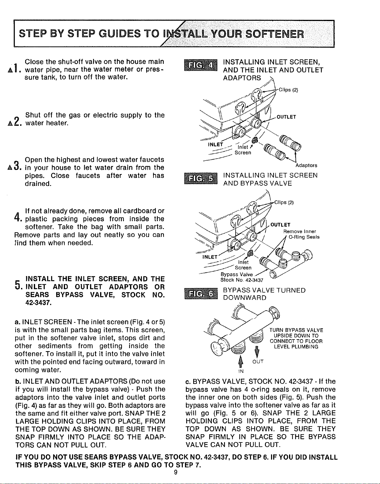
Close the shut-off valve on the house main
A], water pipe, near the water meter or pres-
sure tank, to turn off the water.
Shut off the gas or electric supply to the
A 2. water heater.
Open the highest and lowest water faucets
AO. in your house to let water drain from the
pipes. Close faucets after water has
drained.
INSTALLING INLET SCREEN,
AND THE INLET AND OUTLET
ADAPTORS
Adaptors
INSTALLING INLET SCREEN
AND BYPASS VALVE
If not already done, remove all cardboard or
4. plastic packing pieces from inside the
softener. Take the bag with small parts.
Remove parts and lay out neatly so you can
_ind them when needed.
OUTLET
Remove Inner
O-Ring Seals
INSTALL THE INLET SCREEN, AND THE
t_
_. INLET AND OUTLET ADAPTORS OR
SEARS BYPASS VALVE, STOCK NO.
42-3437.
_Screen
Stock No 42-3437
BYPASS VALVE TURNED
DOWNWARD
a. INLET SCREEN -The inlet screen (Fig. 4 or 5)
is with the small parts bag items. This screen,
put in the softener valve inlet, stops dirt and
other sediments from getting inside the
softener. To install it, put it into the valve inlet
with the pointed end facing outward, toward in
coming water. IN
OUT
TURN BYPASS VALVE
UPSIDE DOWN TO
CONNECT TO FLOOR
LEVEL PLUMBING
b. INLET AND OUTLET ADAPTORS (Do not use
if you will install the bypass valve) - Push the
adaptors into the valve inlet and outlet ports
(Fig. 4) as far as they will go. Both adaptors are
the same and fit either valve port. SNAP THE 2
LARGE HOLDING CLIPS INTO PLACE, FROM
THE TOP DOWN AS SHOWN. BE SURE THEY
SNAP FIRMLY INTO PLACE SO THE ADAP-
TORS CAN NOT PULL OUT,
o. BYPASS VALVE, STOCK NO. 42-3437 - If the
bypass valve has 4 o-ring seals on it, remove
the inner one on both sides (Fig. 5). Push the
bypass valve into the softener valve as far as it
will go (Fig. 5 or 6). SNAP THE 2 LARGE
HOLDING CLIPS INTO PLACE, FROM THE
TOP DOWN AS SHOWN. BE SURE THEY
SNAP FIRMLY IN PLACE SO THE BYPASS
VALVE CAN NOT PULL OUT.
IF YOU DO NOT USE SEARS BYPASS VALVE, STOCK NO. 42-3437, DO STEP 6. IF YOU DID INSTALL
THIS BYPASS VALVE, SKIP STEP 6 AND GO TO STEP 7.
9
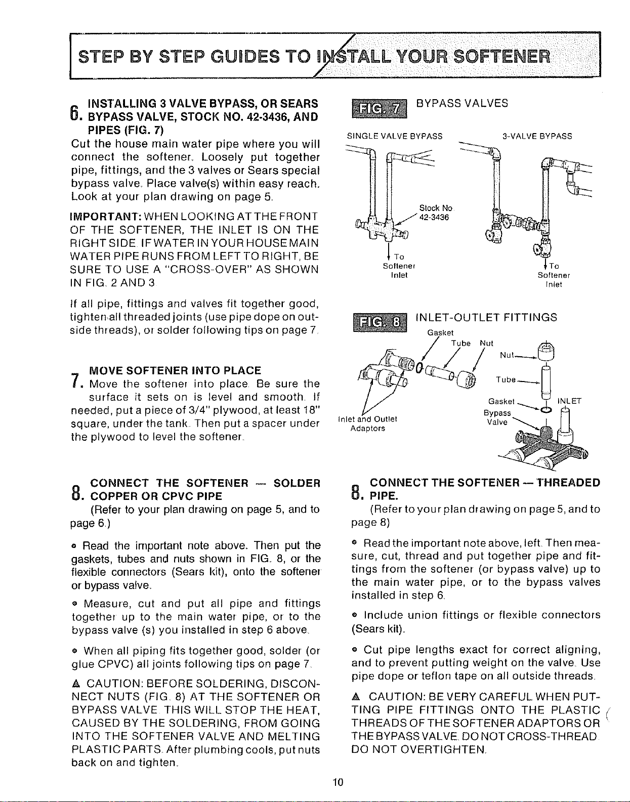
INSTALLING3VALVEBYPASS,ORSEARS
6. BYPASS VALVE, STOCK NO. 42-3436, AND
PIPES (FIG. 7)
Cut the house main water pipe where you will
connect the softener. Loosely put together
pipe, fittings, and the 3 valves or Sears special
bypass valve. Place valve(s) within easy reach.
Look at your plan drawing on page 5.
IMPORTANT: WHEN LOOKING ATTHE FRONT
OF THE SOFTENER, THE INLET IS ON THE
RIGHTSIDE IFWATER IN YOUR HOUSEMAIN
WATER PiPE RUNS FROM LEFT TO RIGHT, BE
SURE TO USE A "CROSS-OVER" AS SHOWN
IN FIG, 2 AND 3
If all pipe, fittings and valves fit together good,
tighten,all threaded joints (use pipe dope on out-
side threads), or solder following tips on page 7
MOVE SOFTENER INTO PLACE
[, Move the softener into place Be sure the
surface it sets on is level and smooth If
needed, put a piece of 3/4" plywood, at least t8"
square, under the tank Then put a spacer under
the plywood to level the softener
BYPASSVALVES
SINGLE VALVE BYPASS
tl Stock NO
_ _ 42-3436
To
Softener
Inlet
3_VALVE BYPASS
_To
Softener
Inlet
INLET-OUTLET FITTINGS
Gasket
Inlet and Outlet Valve
Adaptors
CONNECT THE SOFTENER -- SOLDER
8. COPPER OR CPVC PIPE
(Refertoyourplandrawingonpage5, andto
page6)
• Read the important note above. Then put the
gaskets, tubes arrd nuts shown in FIG. 8, or the
flexible corrnectors (Sears kit), onto the softener
or bypass valve.
o Measure, cut and put all pipe and fittings
together up to the main water pipe, or to the
bypass valve (s) you installed in step 6 above.
o When all piping fits together good, solder (or
glue CPVC) all joints following tips on page 7
,_. CAUTION: BEFORE SOLDERING, DISCON-
NECT NUTS (FIG 8) AT THE SOFTENER OR
BYPASS VALVE THIS WILL STOP THE HEAT,
CAUSED BY THE SOLDERING, FROM GOING
INTO THE SOFTENER VALVE AND MELTING
PLASTIC PARTS After plumbing cools, put nuts
back on and tighten
CONNECT THE SOFTENER -- THREADED
8, PIPE.
(Refer to your plan drawing on page 5, and to
page 8)
e Read the important note above, left. Then mea-
sure, cut, thread and put together pipe and fit-
tings from the softener (or bypass valve) up to
the main water pipe, or to the bypass valves
installed in step 6.
o Include union fittings or flexible connectors
(Sears kit).
o Cut pipe lengths exact for correct aligning,
and to prevent putting weight on the valve Use
pipe dope or teflon tape on all outside threads,
,& CAUTION: BE VERY CAREFUL WHEN PUT-
TING PIPE FITTINGS ONTO THE PLASTIC (
THREADS OF THE SOFTENER ADAPTORS OR
THE BYPASS VALVE. DO NOT CROSS-THREAD
DO NOT OVERTIGHTEN
10
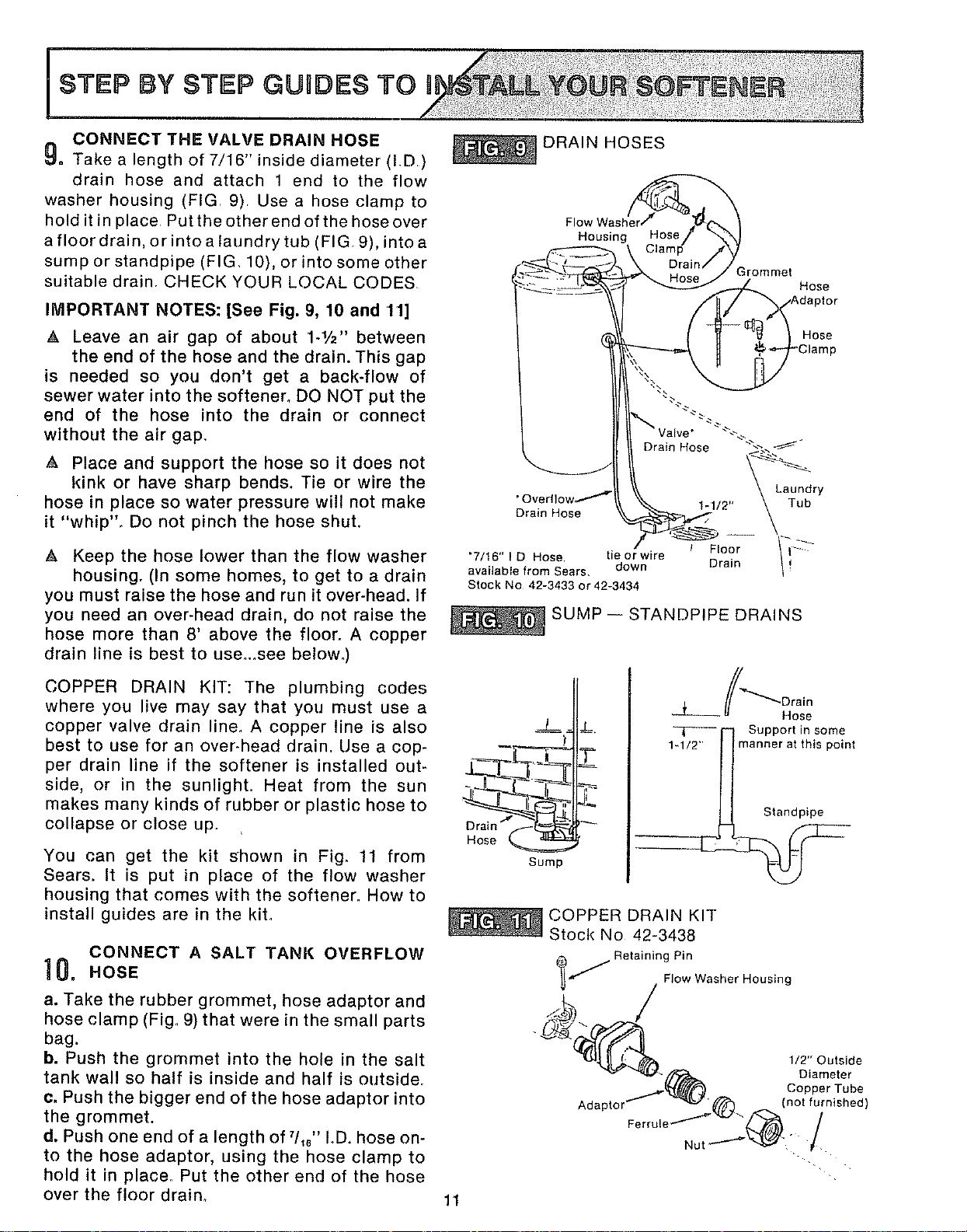
CONNECT THE VALVE DRAIN HOSE
_. Take a length of 7/16" inside diameter (I,D)
drain hose and attach 1 end to the flow
washer housing (FIG, 9) Usea hose clamp to
hold itin place Put the other end of the hose over
a floor drain, or intoalaundrytub (FIG, 9), intoa
sump or standpipe (FIG 10), or into some other
suitable drain, CHECK YOUR LOCAL CODES
IMPORTANT NOTES: [See Fig. 9, 10 and tl]
A Leave an air gap of about 1-1/2'' between
the end of the hose and the drain. This gap
is needed so you don't get a back-flow of
sewer water into the softener° DO NOT put the
end of the hose into the drain or connect
without the air gap,
A Place and support the hose so it does not
kink or have sharp bends. Tie or wire the
hose in place so water pressure will not make
it "whip", Do not pinch the hose shut.
A Keep the hose lower than the flow washer
housing. (In some homes, to get to a drain
you must raise the hose and run it over-head. If
you need an over-head drain, do not raise the
hose more than 8' above the floor. A copper
drain line is best to use__see below.)
COPPER DRAIN KIT: The plumbing codes
where you live may say that you must use a
copper valve drain line, A copper line is also
best to use for an over-head drain. Use a cop-
per drain line if the softener is installed out-
side, or in the sunlighL Heat from the sun
makes many kinds of rubber or plastic hose to
collapse or close up.
You can get the kit shown in Fig. 11 from
Sears. It is put in place of the flow washer
housing that comes with the softener. How to
install guides are in the kit.
CONNECT A SALT TANK OVERFLOW
10. HOSE
a. Take the rubber grommet, hose adaptor and
hose clamp (Fig. 9) that were in the small parts
bag.
b. Push the grommet into the hole in the salt
tank wall so half is inside and half is outside,
c. Push the bigger end of the hose adaptor into
the grommet.
d. Push one end of a length of qls" IoD. hose on-
to the hose adaptor, using the hose clamp to
hold it in place. Put the other end of the hose
over the floor drain,
DRAIN HOSES
Housing Hose
irommet
Hose
Hose
Drain Hose
Laundry
• Overfl °w_"_ 1-1/2" Tub
Drain Hose
"7/16" I D Hose, tie or wire
available from Sears, down
Stock No 42-3433 or 42-3434
/ Floor -_
Drain
SUMP-- STANDPIPE DRAINS
J_
_1 ---)i
- t
Sump
Hose
-T_ i'- I Support in some
1-1/2"_manner at this point
COPPER DRAIN KIT
Stock No 42-3438
Retaining Pin
_..,/ Flow Washer Housing
Adaptor'
Fe
Nut
1/2" Outside
Diameter
Copper Tube
(not furnished)
/
11
i STEP BY STEP GUnDES TO #
IMPORTANT NOTES:
e The salt tank overflow is for safety only It
directs over-fill water from the salt storage
tank to the drain.
Over-fill water must run downward through
the hose Do not raise the hose higher than
the grommet and hose adaptor (FIG 9).
DO NOT connect to the valve drain hose you
installed in step9 A separate hose is needed
for both drains
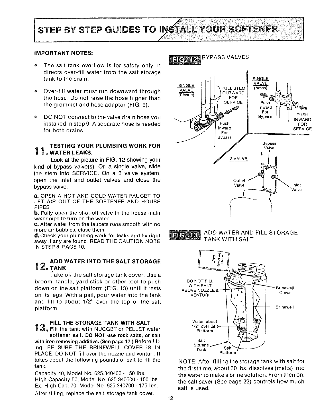
TESTINGYOURPLUM INGWO.KFOR
I 1.WATERLEAKS.
Look at the picture in FIG. 12 showing your
kind of bypass valve(s). On a single valve, slide
the stem into SERVICE.. On a 3 valve system,
open the inlet and outlet valves and close the
bypass valve.
a. OPEN A HOT AND COLD WATER FAUCET TO
LET AiR OUT OF THE SOFTENER AND HOUSE
PIPES
b. Fully open the shut-off valve in the house main
water pipe to turn on the water
C. After water from the faucets runs smooth with no
more air bubbles, close them
d. Check your plumbing work for leaks and fix right
away if any are found READ THE CAUTION NOTE
IN STEP 8, PAGE 10
__ ADD WATER INTO THE SALT STORAGE
I Z. TANK
Take off the salt storage tank cover_ Use a
broom handle, yard stick or other tool to push
down on the salt p[atforrn (FIG 13) until it rests
on its legs. With a pail, pour water into the tank
and fill to about 1/2" over the top of the salt
platform
FILL THE STORAGE TANK WITH SALT
_=_=Fill the tank with NUGGET of PELLET water
softener salt,. DO NOT use rock salts, or salt
with iron removing additive. (See page 17.) Before fill-
ing, BE SURE THE BRINEWELL COVER IS IN
PLACE, DO NOT fill over the nozzle and venturL It
takes about the following pounds of salt to fill the
tank_
Capacity 40, Model No 625.340400 - 150 Ibs
High Capacity 50, Model No 625.340500 - 150 Ibs.
Ex. High Cap. 70, Model No 625340700 - 175 Ibs.
After filling, replace the salt storage tank cover_
BYPASS VALVES
SINGLE
VALVE
(Plastic)
PULL STEM
OUTWARD
FOR
SERVICE
inward
For ,....
Bypass
SINGLE
VALVE
(brass)
Push_
Inward
For
Bypass
Bypass
Valve
PUSH
INWARD
FOR
SERVICE
Outlet
Valve Inlet
ADD WATER AND FILL STORAGE
TANK WITH SALT
-4 z_
DO NOT FILL _',_= / f--_'t_._ I
WITH SALT
ABOVE NOZZLE &_
VENTURI
Water about
1/2" over Salt--
Platform
Salt
Storage/ t_
Tank
Platform'
Brinewell
Cover
--8rinewell
NOTE: After filling the storage tank with salt for
the first time, about 30 Ibs dissolves (melts) into
the water to makea brinesolution_ From then on,
the salt saver (See page 22) controls how much
salt is used.
12
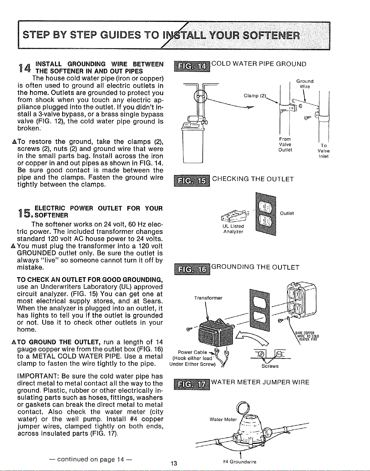
INSTALL GROUNDING WIRE BETWEEN
'_4 THE SOFTENER IN AND OUT PIPES
The house cold water pipe (iron or copper)
is often used to ground all electric outlets in
the home. Outlets are grounded to protect you
from shock when you touch any electric ap-
pliance plugged into the outlet. If you didn't in-
stall a 3-valve bypass, or a brass single bypass
valve (FIGo 12), the cold water pipe ground is
broken.
&To restore the ground, take the clamps (2),
screws (2), nuts (2) and ground wire that were
in the small parts bag. Install across the iron
or copper in and out pipes as shown in FIG. 14.
Be sure good contact is made between the
pipe and the clamps. Fasten the ground wire
tightly between the clamps.
COLD WATER PIPE GROUND
Ground
Wire
Clamp (2)_._
From
Valve
Outlet
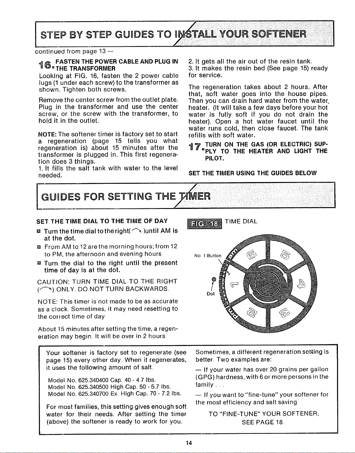
CHECKING THE OUTLET
To
Valve
Inlet
ELECTRIC POWER OUTLET FOR YOUR
1 _. SOFTENER
The softener works on 24 volt, 60 Hz elec-
tric power. The included transformer changes
standard 120 volt AC house power to 24 volts.
AYou must plug the transformer into a 120 volt
GROUNDED outlet only. Be sure the outlet is
always "live" so someone cannot turn it off by
mistake.
TO CHECK AN OUTLET FOR GOOD GROUNDING,
use an Underwriters Laboratory (UL) approved
circuit analyzer, (FIG. 15) You can get one at
most electrical supply stores, and at Sears.
When the analyzer is plugged into an outlet, it
has lights to tell you if the outlet is grounded
or not. Use it to check other outlets in your
home.
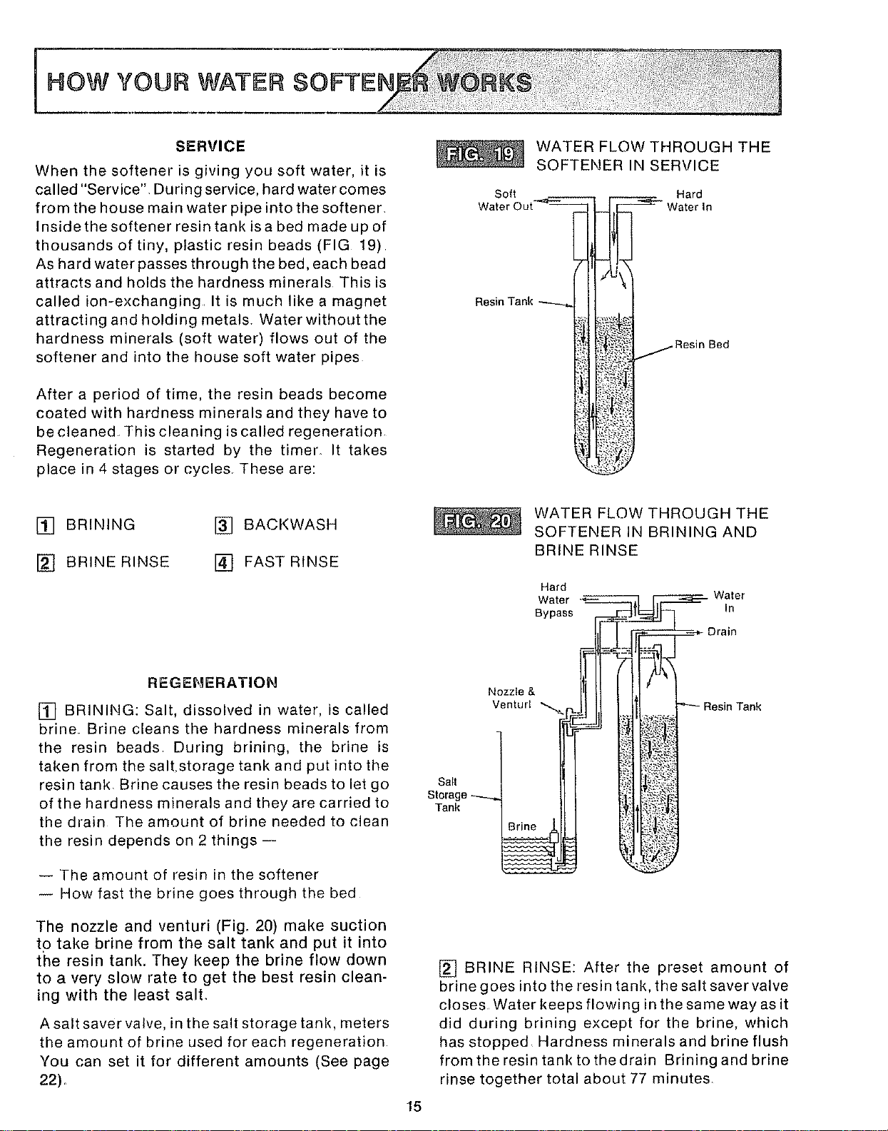
ATO GROUND THE OUTLET, run a length of 14
gauge copper wire from the outlet box (FIG, 16)
to a METAL COLD WATER PIPE Use a metal
clamp to fasten the wire tightly to the pipeo
IMPORTANT: Be sure the cold water pipe has
direct metal to metal contact all the way to the
ground° Plastic, rubber or other electrically in-
sulating parts such as hoses, fittings, washers
or gaskets can break the direct metal to metal
contact. Also check the water meter (city
water) or the well pump° Install #4 copper
jumper wires, clamped tightly on both ends,
across insulated parts (FIG. 17)_
--continued on page 14--
OuUet
UL Listed
Analyzer
GROUNDING THE OUTLET
Transformer
' I
Power Cable -._
(Hook either lead ",_k,_r
Under Either Screw)
Screws
_AREODDPEfl
I0 COLD
WATER METER JUMPER WIRE
13
#4 Groundwire
I STEP GUIDES TO Ul
BY STEP
continued from page 13--
FASTEN THE POWER CABLE AND PLUG IN
=__' =THE TRANSFORMER
Looking at FIG. 16, fasten the 2 power cable
lugs (1 under each screw) to the transformer as
shown,. Tighten both screws.
Remove the center screw from the outlet plate.
Plug in the transformer and use the center
screw, or the screw with the transformer, to
hold it in the outlet.
NOTE: The softener timer is factory set to start
a regeneration (page 15 tells you what
regeneration is) about 15 minutes after the
transformer is plugged ino This first regenera-
tion does 3 things.
1. It fills the salt tank with water to the level
needed.
I GUIDES FOB SETTING THE
2. It gets all the air out of the resin tank,
3. It makes the resin bed (See page 15) ready
for service.
The regeneration takes about 2 hours. After
that, soft water goes into the house pipes,
Then you can drain hard water from the water_
heater° (It will take a few days before your hot
water is fully soft if you do not drain the
heater)_ Open a hot water faucet until the
water runs cold, then close faucet, The tank
refills with soft water.
i7 TURN ON THE GAS (OR ELECTRIC) SUP-
==PLY TO THE HEATER AND LIGHT THE
PILOT.
SET THE TIMER USING THE GUIDES BELOW
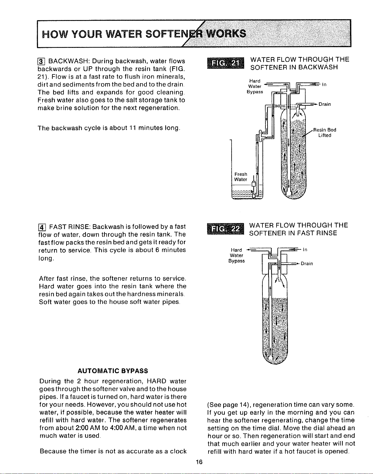
SET THE TIME DIAL TO THE TIME OF DAY
8 Turn the time dial to the right(_ )until AM is
at the dot.
[] From AM to 12 are the morning hours; from t2
to PM, the afternoon and evening hours
[] Turn the dial to the right until the present
time of day is at the dot.
CAUTION: TURN TIME DIAL TO THE RIGHT
(/'-_) ONLY. DO NOT TURN BACKWARDS
NOTE: This timer is not made to be as accurate
as a clock Sometimes, it may need resetting to
the correct time of day
No 1 Sutton
\
Dot
TIME DIAL
About 15 minutes after setting the time, a regen-
eration may begin. It will be over in 2 hours
Your softener is factory set to regenerate (see
page 15) every other day When it regenerates,
it uses the following amount of sail
Model No. 625340400 Cap_ 40 - 4,7 Ibs,
Model Noo 625.340500 High Cap. 50 - 5_7 Ibs.
Model No. 625,,340700 Ex_ High Cap_ 70 - 7,2 Ibs_
For most families, this setting gives enough soft
water for their needs_ After setting the timer
(above) the softener is ready to work for you_
Sometimes, a different regeneration setting is
better Two examples are:
-- If your water has over 20 grains per gallon
(GPG) hardness, with 6 or more persons in the
family. •,
-- If you want to "fine-tune" your softener for
the most efficiency and salt saving
TO "FINE-TUNE" YOUR SOFTENER,
SEE PAGE 18
14
SERVICE
When the softener is giving you soft water, it is
called "Service". During service, hard water comes
from the house main water pipe into the softener.
Inside the softener resin tank isa bed made up of
thousands of tiny, plastic resin beads (FIG 19)
As hard water passes through the bed, each bead
attractsand holds the hardness minerals This is
called ion-exchanging, It is much like a magnet
attracting and holding metals, Water without the
hardness minerals (soft water) flows out of the
softener and into the house soft water pipes
After a period of time, the resin beads become
coated with hardness minerals and they have to
be cleaned This cleaning is called regeneration
Regeneration is started by the timen It takes
place in 4 stages or cycles These are:
WATER FLOW THROUGH THE
SOFTENER IN SERVICE
Soft Hard
Water C
Resin Tank
_. Resin Bed
[] BRINING
[] BRINE RINSE
[] BACKWASH
[] FAST RINSE
REGENERATION
[] BRINING: Salt, dissolved in water, is called
brine Brine cleans the hardness minerals from
the resin beads During brining, the brine is
taken from the salt.storage tank and put into the
resin tank Brine causes the resin beads to let go
of the hardness minerals and they are carried to
the drain The amount of brine needed to clean
the resin depends on 2 things--
-- The amount of resin in the softener
-- How fast the brine goes through the bed
The nozzle and venturi (Fig. 20) make suction
to take brine from the salt tank and put it into
the resin tank. They keep the brine flow down
to a very slow rate to get the best resin clean-
ing with the least salt.
A salt saver valve, in the salt storage tank, meters
the amount of brine used for each regeneration
You can set it for different amounts (See page
22).
WATER FLOW THROUGH THE
SOFTENER IN BRINING AND
BRINE RINSE
Hard
Water
Bypass
Nozzle & i
Venturl "'_I -_
Salt
Storage _ JJ
Tank
In
Drain
;_.?;: _ Resin Tank
15
[] BRINE RINSE: After the preset amount of
brine goes into the resin tank, the salt saver valve
closes Water keeps flowing in the same way as it
did during brining except for the brine, which
has stopped Hardness minerals and brine flush
from the resin tank to the drain Brining and brine
rinse together total about 77 minutes
HOW YOUR WATER SOFTEN
[] BACKWASH: During backwash, water flows
backwards or UP through the resin tank (FIG.
21). Flow is at a fast rate to flush iron minerals,
dirt and sediments from the bed and to the drain
The bed lifts and expands for good cleaning.
Fresh water also goes to the salt storage tank to
make brine solution for the next regeneration
The backwash cycle is about 11 minutes long.
WATER FLOW THROUGH THE
SOFTENER IN BACKWASH
Hard
Water
Bypass
Resin Bed
Lifted
[] FAST RINSE: Backwash is followed bya fast
flow of water, down through the resin tank. The
fast flow packs the resin bed and gets it ready for
return to service. This cycle is about 6 minutes
long.
After fast rinse, the softener returns to service,
Hard water goes into the resin tank where the
resin bed again takes out the hardness minerals
Soft water goes to the house soft water pipes
WATER FLOW THROUGH THE
SOFTENER IN FAST RINSE
Hard _ _ In
Water
Bypass _--------_Drain
AUTOMATIC BYPASS
During the 2 hour regeneration, HARD water
goes through the softener valve and to the house
pipes. If a faucet is turned on, hard water is there
for your needs. However, you should not use hot
water, if possible, because the water heater will
refill with hard water. The softener regenerates
from about 2:00 AM to 4:00 AM,a time when not
rnuch water is used
Because the timer is not as accurate as a clock
16
(See page 14), regeneration time can vary some.
If you get up early in the morning and you can
hear the softener regenerating, change the time
setting on the time dial, Move the dial ahead an
hour or so. Then regeneration will start and end
that much earlier and your water heater will not
refill with hard water if a hot faucet is opened
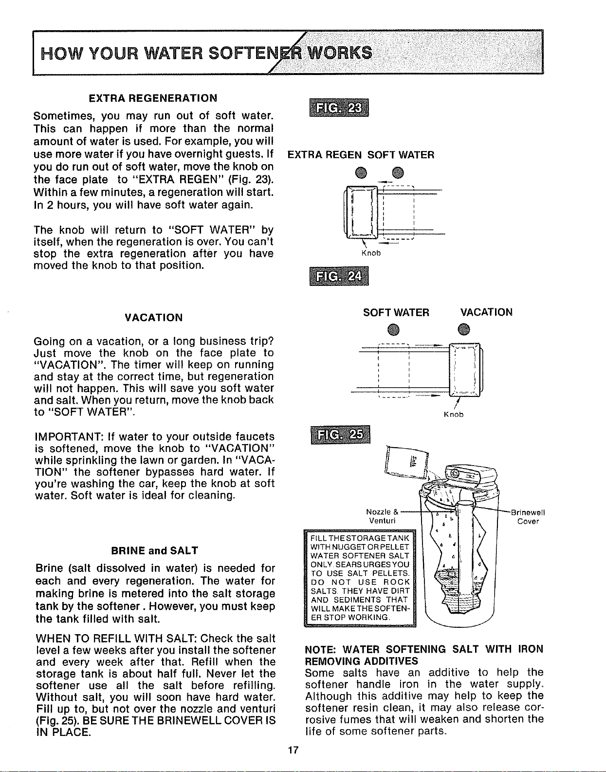
EXTRA REGENERATION
Sometimes, you may run out of soft water.
This can happen if more than the normal
amount of water is used. For example, you will
use more water if you have overnight guests. If
you do run out of soft water, move the knob on
the face plate to "EXTRA REGEN" (Fig. 23).
Within a few minutes, a regeneration will start.
In 2 hours, you will have soft water again.
The knob will return to "SOFT WATER" by
itself, when the regeneration is over. You can't
stop the extra regeneration after you have
moved the knob to that position•
EXTRA REGEN SOFT WATER
@ @
i L
I
I I
I I
i J
R I
Knob
VACATION
Going on a vacation, or a long business trip?
Just move the knob on the face plate to
"VACATION". The timer will keep on running
and stay at the correct time, but regeneration
will not happen. This will save you soft water
and salt. When you return, move the knob back
to "SOFT WATER".
IMPORTANT: If water to your outside faucets
is softened, move the knob to "VACATION"
while sprinkling the lawn or garden. In "VACA-
TION" the softener bypasses hard water. If
you're washing the car, keep the knob at soft
water. Soft water is ideal for cleaning.
BRINE and SALT
Brine (salt dissolved in water) is needed for
each and every regeneration. The water for
making brine is metered into the salt storage
tank by the softener. However, you must keep
the tank filled with salt.
WHEN TO REFILL WITH SALT: Check the salt
level a few weeks after you install the softener
and every week after that. Refill when the
storage tank is about half full. Never let the
softener use all the salt before refilling.
Without salt, you will soon have hard water.
Fill up to, but not over the nozzle and venturi
(Fig. 25). BE SURE THE BRINEWELL COVER IS
IN PLACE.
SOFT WATER VACATION
® ®
i t
I P
k I
P i
'r '
Knob
Nozzle&-- _ "_'_
Venturi
FILL THESTORAGETANK
WITH NUGGET OR PELLET
WATER SOFTENER SALT
ONLY SEARS URGES YOU
TO USE SALT PELLETS.
DO NOT USE ROCK
SALTS THEY HAVE DIRT
AND SEDIMENTS THAT
WILL MAKETHE SOFTEN-
ER STOP WORKING
_Brinewell
Cover
17
NOTE: WATER SOFTENING SALT WITH IRON
REMOVING ADDITIVES
Some salts have an additive to help the
softener handle iron in the water supply,,
Although this additive may help to keep the
softener resin clean, it may also release cor-
rosive fumes that will weaken and shorten the
life of some softener parts,
HOW TO "FliNE=TUNE" YOUR
It's not hard to "fine-tune" your softener (See
page 14), but it does take a few minutes of your
time to do it right. You may save up to 500
pounds or more or salt each year with proper
tuning. Read the following carefully.
To have soft water all the time, the softener
must regenerate 1 or more times in each 6 day
period. How many times to regenerate (set on
the time dial) and the salt saver setting to use
depends on 2 things.
1.The number of people in your home-tellsyou
how much water is used
2. The grains per gallon (GPG) hardness of your
water supply -- listed on your water analysis
report .... see page 4.
The softener regenerates with salt (brine - see
page 15)_ The pounds of salt needed each regen-
eration is set on the salt saver valve The salt
saver on your softener is set for_
.....4.7 Ibs - Model No. 625340400 Capacity 40
._5_7 Ibs_ - Model No_ 625_340500 High Cap. 50
.....7.2 Ibs.- Model No. 625..340700 Ex High Cap. 70
This setting gives you soft water for the longest
time before the next regeneration is needed.
However, you will get more gallons of soft water
for each pound of salt used if the softener is re-
generated more often at a lower salt saver set-
ting. Over a period of time, a lower salt setting
will save you salt, and money_
meeting point, pictures of the time dial and salt
saver show you the settings to use The time dial
picture shows you the button numbers to push
inward (See below)The salt saver picture shows
you the number to set your salt saver at (See
page 22).
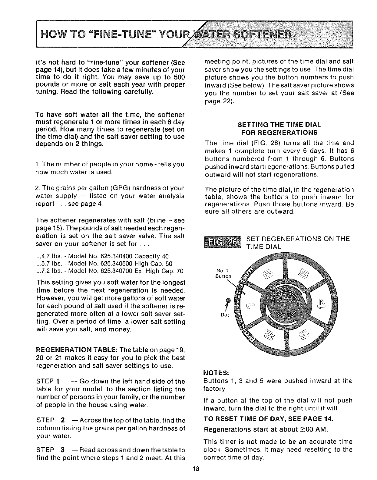
SETTING THE TIME DIAL
FOR REGENERATIONS
The time dial (FIG 26) turns all the time and
makes 1 complete turn every 6 days It has 6
buttons numbered from 1 through 6 Buttons
pushed inward start regenerations. Buttons pulled
outward will not start regenerations
The picture of the time dial, in the regeneration
table, shows the buttons to push inward for
regenerations. Push those buttons inward Be
sure all others are outward.
SET REGENERATIONS ON THE
TIME DIAL
No 1
Button
Dot
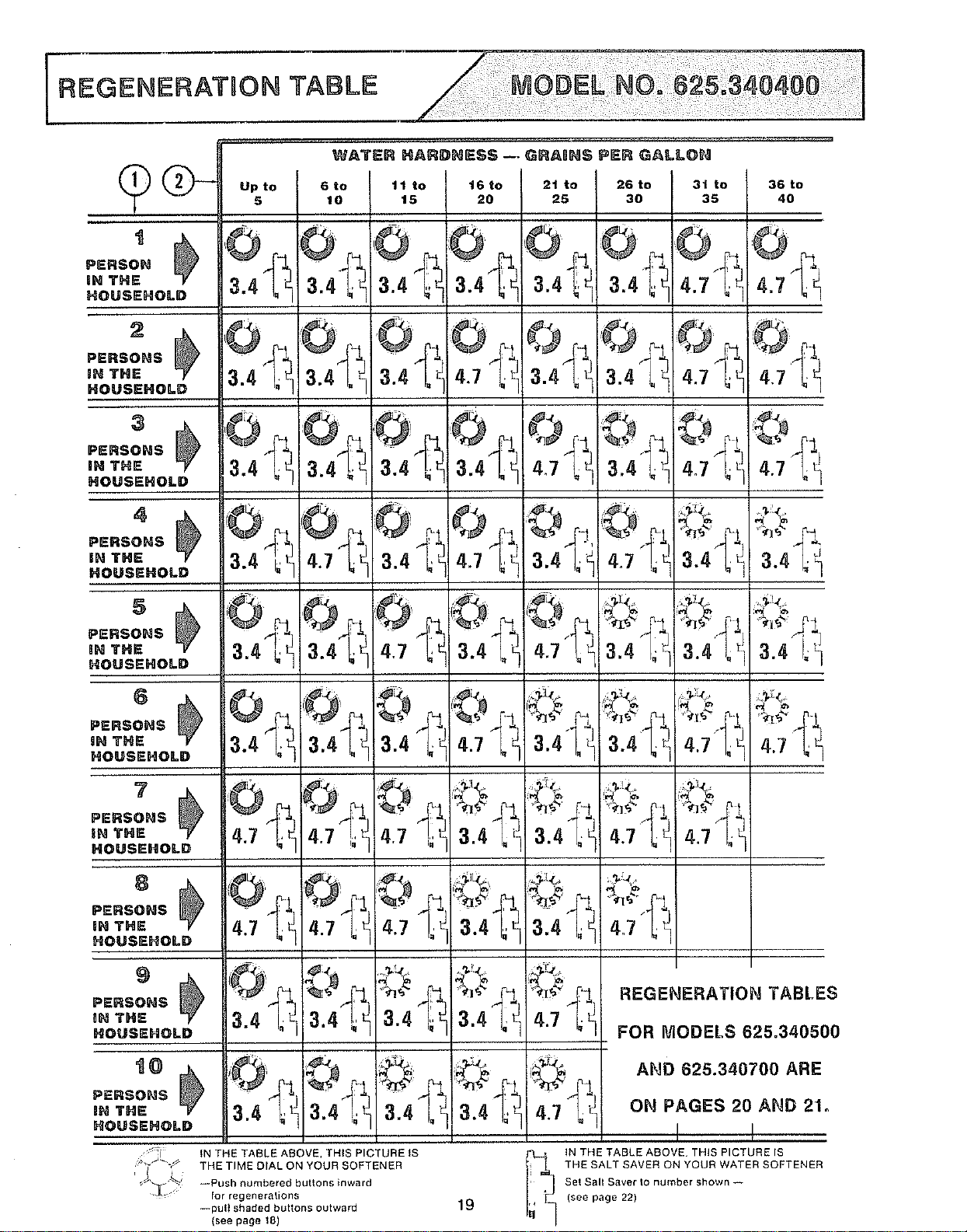
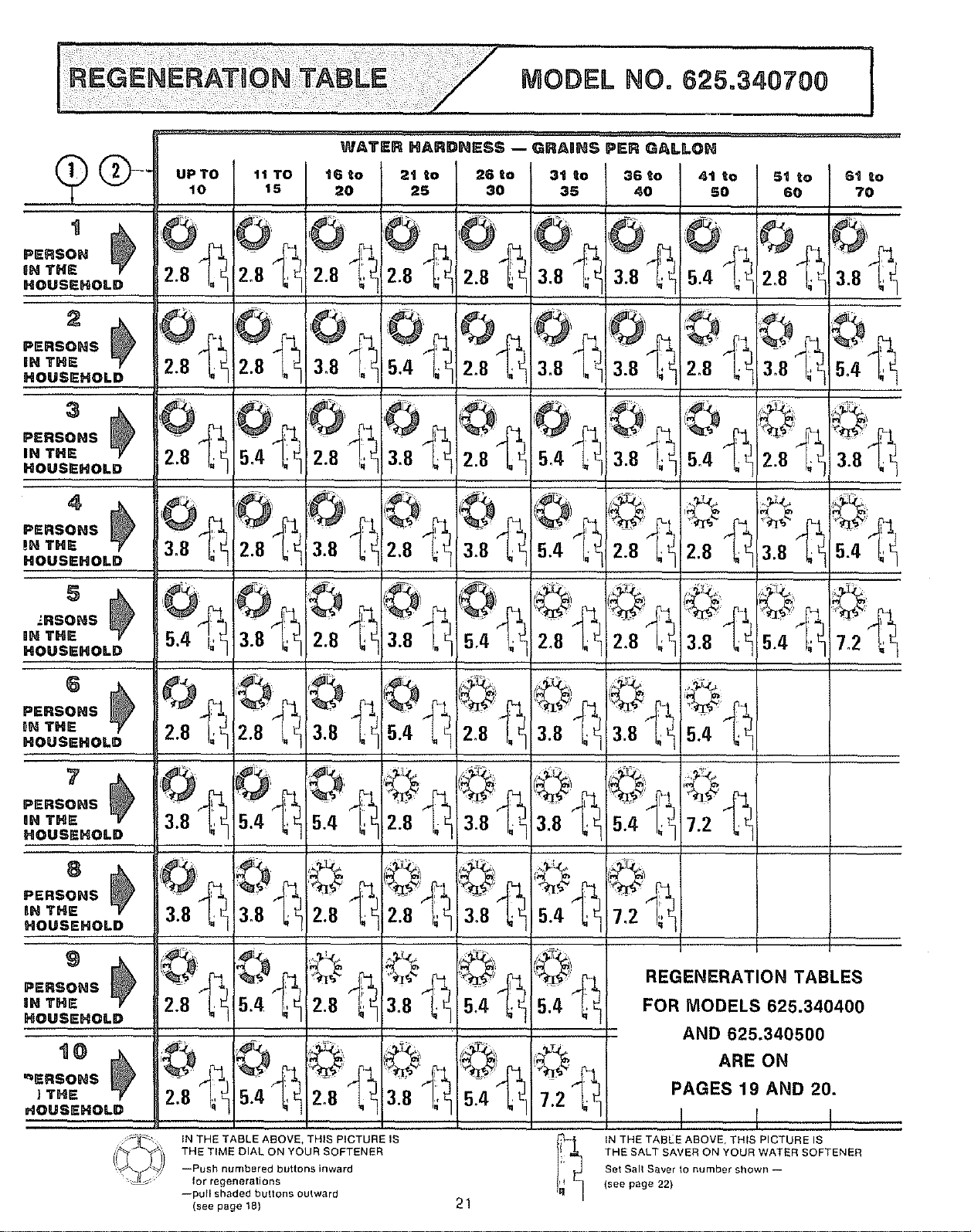
REGENERATION TABLE: The table on page 19,
20 or 21 makes it easy for you to pick the best
regeneration arrd salt saver settings to use_
STEP 1 -- Go down the left hand side of the
table for your rnodel, to the section listing the
number of persons in your family, or the number
of people in the house using water.
STEP 2 --Acrossthetopofthetable, findthe
column listing the grains per gallon hardness of
your water.
STEP 3 --Readacrossanddownthetableto
find the point where steps l and 2 meet At this
18
NOTES:
Buttons 1, 3 and 5 were pushed inward at the
factory
If a button at the top of the dial will not push
inward, turn the dial to the right until it will
TO RESET TIME OF DAY, SEE PAGE 14,
Regenerations start at about 2:00 AM.
This timer is not made to be an accurate time
clock Sometimes, it may need resetting to the
correct time of day
REGENERATBON TABLE
t
_ERSOH _
H THE
_OUSEHOLD
2
:E.so.s ! }
IN THE
_OUSEHOLD
3
ps.so.s _
IEI THE
HOUSEHOLD
4
PERSO.S _
BH THE
HOUSEHOLD
5
PE.SOHSf _
IH THE
HOUSEHOLD
6
PE.SOHS__
iN THE
HOUSEHOLD
?
pE.so.s I _
iN THE
HOUSEHOLD
PERSONS
iN THE i
HOUSEHOLD
PERSONS
aN THE
HOUSEHOLD
t0
PE.SOHSI }
iN THE
HOUSEHOLD
................WATS""ARD"sSS-aRA".SPE._ALLO.
Up to 6 to 11 to
5 10 15
1
. 3
3.4 ;e
0 ©
i3.4 _;e 4.7 at
4.7 _,,_-0I 4.7!_ _ 4r7
4.7 _"1 4.7 Lt 417 "_7
_T_:, _
IN THE TABLE ABOVE, THIS PICTURE IS
THE TIME DIAL ON YOUR SOFTENER
--Push numbered butlons inward
for regenerations
--pull shaded buttons outward
(see Rage tS)
16 to 21 to
20 25
4.7 I_< 3.4_'1,_1
3.4 ],
3.4 L_I 4.7 I,_
4;7cqa.4l.,:
_ 3,4|. _
a;4"l,q
3.4l_ 4.7 "_/':!
b,
19
26 to
30
3.4 ;_
3.4 Le
4.7 ",; t
3,4
3.4"_'
4.7 I__
3t to 36 to
35 40
4.7 L,_ 4.7 it
4.7"1; _: 4.7
<?
I
REGENERATION TABLEI
FOR MODELS 625.34050
AND 625.340700 ARE
ON PAGES 20 AND 21o
I !
iN THE TABLE ABOVE, THIS PICTURE IS
THE SALT SAVER ON YOUR WATER SOFTENER
Set Sail Saver to number shown --
(see page 22)
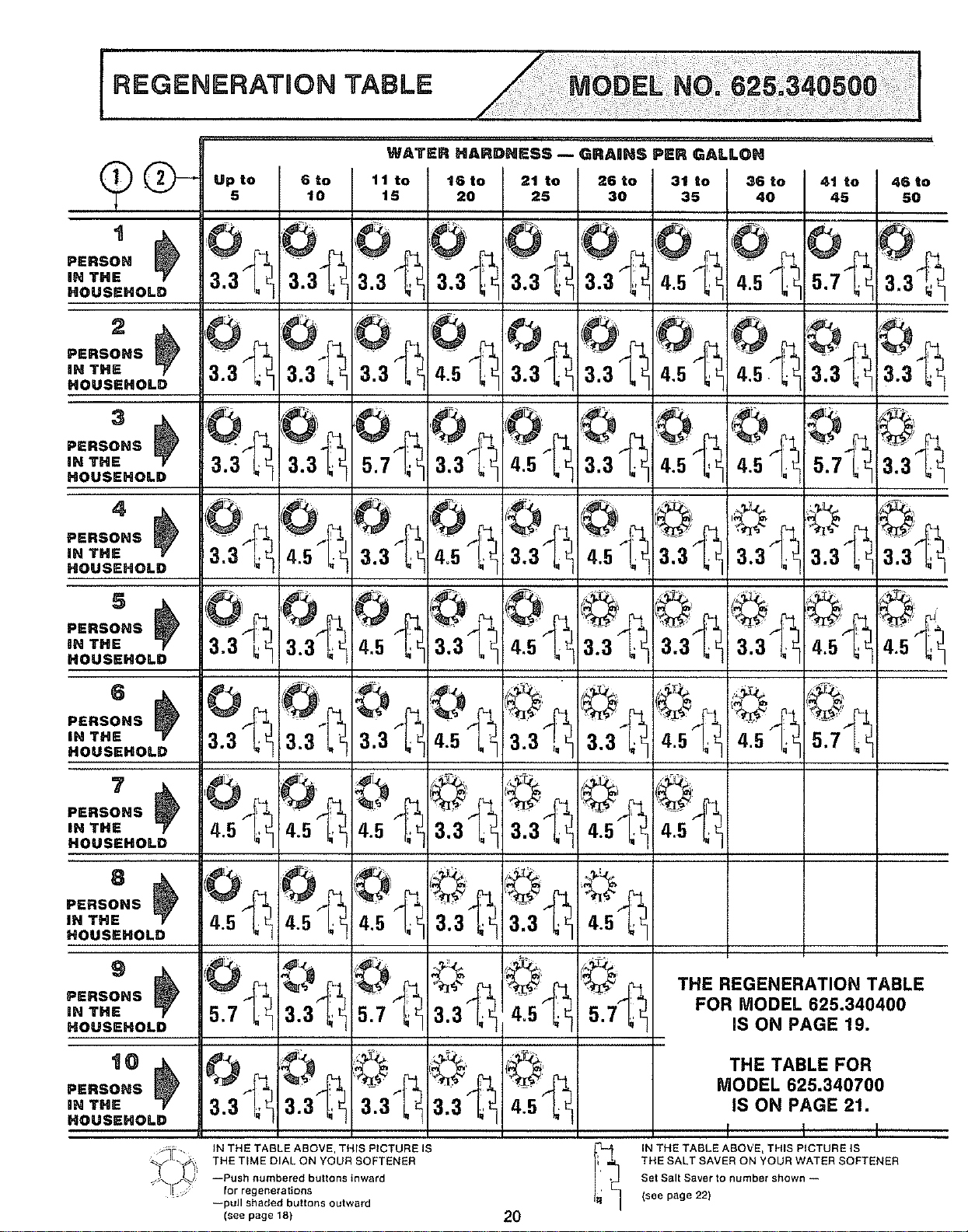
REGENERATION TABLE
Upto 6to 11 to 16to
5 10 15 20
21 to 26 to
25 30
36 to
40
41 to 46 to
45 50
5.7? _
..so..m} 70.
,OUSeHOLD 3.3 [4_:
ERSONS - )
6
eRso.s _
THE
IOUSEHOLD
7
THE
IOUSEHOLD
ERSONS
THE
OUSEHOLD
g
s.so.s _
I THE
IOUSEHOLD
t0
_l THE
IOUSEHOLD
3.3_
4.5I_,
_
3.3 U
0
4.5k _
3.3 _)
a'a@
4.5 t_
4.5 t._
5.7 ";_
3;3"_
3.3L_
4.5_
5.7 ¸_
©.
47,
THE REGENERATION TABLE
FOR MODEL 625.340400
IS ON PAGE 19.
THE TABLE FOR
IN THE TABLE ABOVE, THIS PICTURE IS
THE TIME DIAL ON YOUR SOFTENER
--Push numbered buttons inward
for regenerations
--pull shaded buttons outward
(see page 18)
MODEL 625.340700
IS ON PAGE 21.
2O
I 1 I
IN THE TABLE ABOVE, THIS PICTURE IS
THE SALT SAVER ON YOUR WATER SOFTENER
Set SaR Saver to number shown --
(see page 22)
lil=ll==="
MODEL NO= 625o340700
I
PERSON
0N THE
HOUSEHOLD
PERSONS
iN THE
HOUSEHOLD
PERSONS
IN THE
HOUSEHOLD
PERSONS
IN THE
HOUSEHOLD
5
"RSONS
IN THE
HOUSEHOLD
6
PERSONS
IN THE
HOUSEHOLD
7
PERSONS
IN THE
HOUSEHOLD
8
PERSONS
IN THE
HOUSEHOLD
PERSONS
IN THE
HOUSEHOLD
t0
qERSONS
JTHE
HOUSEHOLD
IN THE TABLE ABOVE, THIS PICTURE IS
THE TIME DIAL ON YOUR SOFTENER
--Push numbered buttons inward
for regenerations
--pull shaded buttons outward
(see page 18)
21
REGENERATION TABLES
FOR MODELS 625.340400
AND 625.340500
ARE ON
PAGES 19 AND 20.
I I I
NTHEHPCTURES
THE SALT SAVER ON YOUR WATER SOFTENER
Set Sail Saver to number shown --
(see page 22)
HOW TO "FnNE=TUNE"
SETTING THE SALT SAVER
NOTE: Read page 18 before resetting the salt
saver
The salt saver(FIG 28) is set bysliding a stem up
or down This raises or lowers a hose into the
/
brine solution to control salt (brine) use_ The
sliding stem has number markings on it It is
factory set at
o_4_7 for 4.7 Ibs. salt - Model No, 625,340400
...5.7 for 5.7 Ibs. salt - Model No, 625.340500
_.7_2 for 7.2 Ibs. salt - Model No. 625.340700
To change the setting, do the following
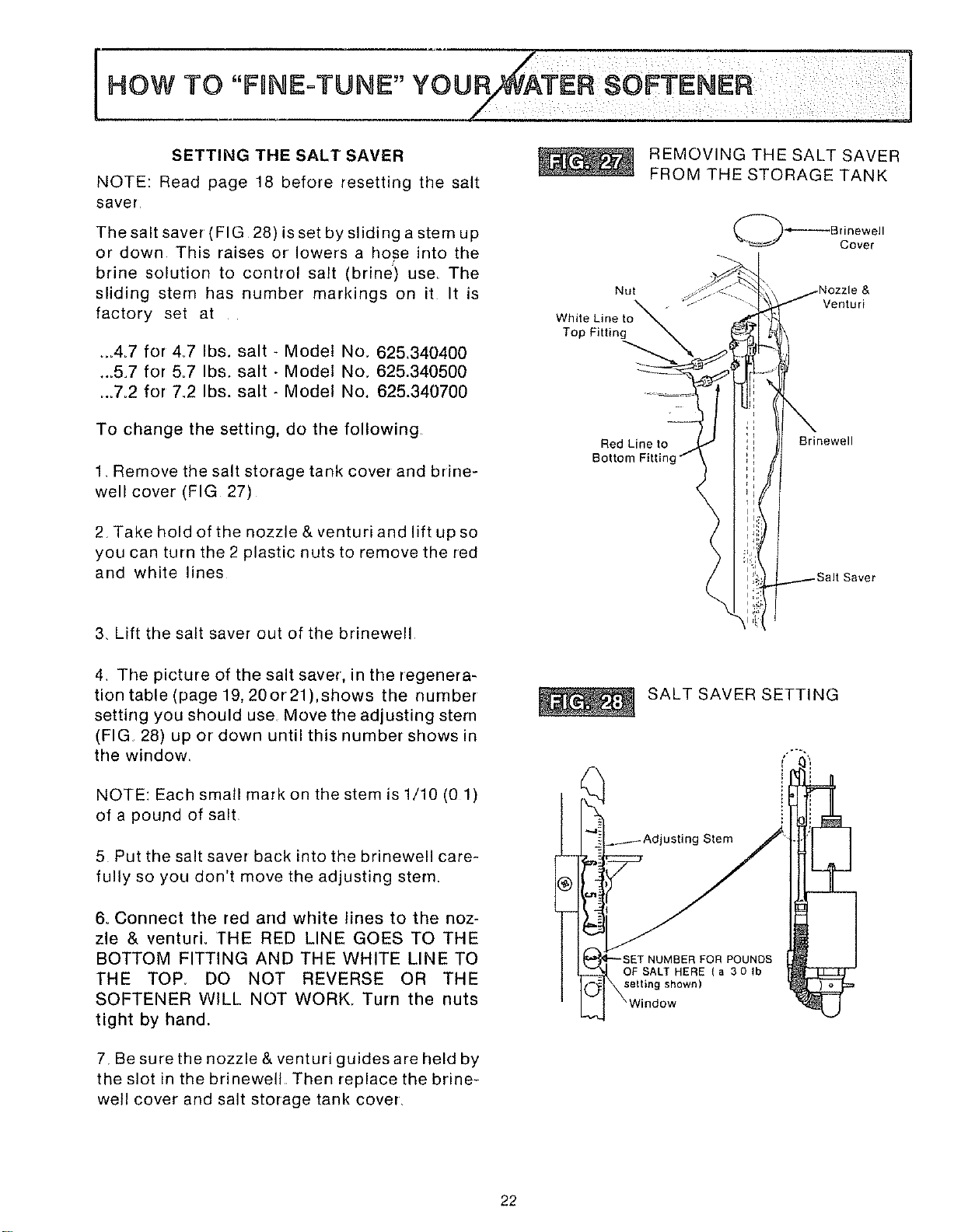
1 Remove the salt storage tank cover and brine-
well cover (FIG 27)
2 Take hold of the nozzle & venturiand lift up so
you can turn the 2 plastic nuts to remove the red
and white lines
Nut
Whit
Top Fitting
Red Line to
Bottom Fittinc
REMOVING THE SALT SAVER
FROM THE STORAGE TANK
Venturi
Brinewell
3, Lift the salt saver out of the brinewell
4 The picture of the salt saver, in the regenera-
tion table (page 19,20or21),shows the number
setting you should use Move the adjusting stem
(FIG 28) up or clown until this number shows in
the window_
NOTE: Each small mark on the stem is 1/10 (0 1)
of a pound of salt
5 Put the salt saver back into the brinewell care-
fully so you don't move the adjusting stern_
6o Connect the red and white lines to the noz-
zle & venturi. THE RED LINE GOES TO THE
BOTTOM FITTING AND THE WHITE LINE TO
THE TOE DO NOT REVERSE OR THE
SOFTENER WILL NOT WORK. Turn the nuts
tight by hand.
7. Be sure the nozzle& venturiguidesare held by
the slot in the brinewell Then replace the brine-
well cover and salt storage tank cover
SALT SAVER SETTING
usting Stem
FOR POUNDS
OF SALT HERE (a 30 Ib
selting shown)
22
I HOW TO CARE FOR YOUR
CLEANING THE COVERS
To keep your new Sears water softener looking
nice, apply a coat of paste wax and repeat
once a year. When dusty, wipe it with a damp
cloth to keep it sparkling.
ANever use cleaners having ammonia or abra-
sives. They may scratch and dull the surface
CLEANING THE NOZZLE & VENTURI
Aclean nozzle and venturi(FIG 29) isa must for
the softener to work right. This small unit moves
brine from the salt storage tank to the resin tank
during regeneration If it becomes plugged with
sand, silt, dirt, etc_, it will not move the brine, and
you will get hard water.
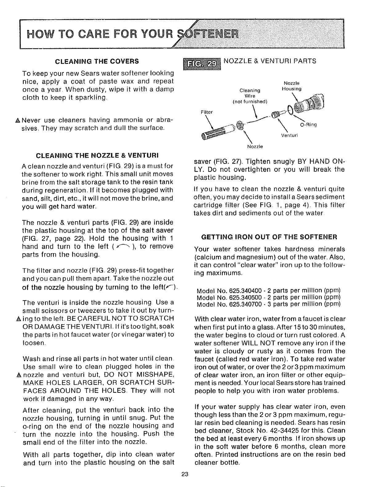
The nozzle & venturi parts (FIG. 29) are inside
the plastic housing at the top of the salt saver
(FIG. 27, page 22). Hold the housing with 1
hand and turn to the left (f---.), to remove
parts from the housing_
The filter and nozzle (FIG 29) press-fit together
and you can pull themaparLTakethe nozzle out
of the nozzle housing by turning to the left(F).
The venturi is inside the nozzle housing Usea
small scissors or tweezers to take it out by turn-
A ing to the left. BE .CAREFUL NOT TO SCRATCH
OR DAMAGE THE VENTUR L If it's too tight, soak
the parts in hot faucet water (or vinegar water) to
loosen,
Wash and rinse all parts in hot water until clean
Use small wire to clean plugged holes in the
A nozzle and venturi but, DO NOT MISSHAPE,
MAKE HOLES LARGER, OR SCRATCH SUR-
FACES AROUND THE HOLES. They will not
work if damaged in any way
After cleaning, put the venturi back into the
nozzle housing, turning in until snug° Put the
o-ring on the end of the nozzle housing and
turn the nozzle into the housing. Push the
small end of the filter into the nozzle.
With all parts together, dip into clean water
and turn into the plastic housing on the salt
NOZZLE & VENTURI PARTS
Nozzle
Cleaning Housing
(not fu_rniehed) _
Nozzle
saver (FIG. 27).. Tighten snugly BY HAND ON-
LY. Do not overtighten or you will break the
plastic housing.
If you have to clean the nozzle & venturi quite
often, you may decide to install a Sears sediment
cartridge filter (See FIG 1, page 4) This filter
takes dirt and sediments out of the water
GETTING IRON OUT OF THE SOFTENER
Your water softener takes hardness minerals
(calcium and magnesium) out of the water Also,
it can control "clear water" iron up to the follow-
ing maximums.
Model No, 625,340400 _2 parts per million (ppm)
Model No, 625_340500 - 2 parts per million (ppm)
Model No. 62&340700 - 3 parts per million (ppm)
With clear water iron, water from a faucet is clear
when first put into a glass. After 15 to 30 minutes,
the water begins to cloud or turn rust colored A
water softener WILL NOT remove any iron if the
water is cloudy or rusty as it comes from the
faucet (called red water iron). To take red water
iron out of water, or over the 2 or 3 ppm maximum
of clear water iron, an iron filter or other equip-
ment is needed. Your local Sears store has trained
people to help you with iron water problem&
If your water supply has clear water iron, even
though less than the 2or3 ppm maximum, regu-
lar resin bed cleaning is needed. Sears has resin
bed cleaner, Stock No. 42-34425 for this Clean
the bed at least every6 months. If iron shows up
in the soft water before 6 months, clean more
often Printed instructions are on the resin bed
cleaner bottle.
23
¸¸ iiiii i!¸i!il !iii .owTocA.E You.
BREAKING A SALT BRIDGE
Sometimes, a hard crust or salt bridge forms in
the salt storage tank, just above the salt platform
It is often caused by high humidity (dampness in
the air) or the wrong kind of salt When the salt
bridges, an empty space forms between the
water and salt Then salt will not dissolve (melt)
in the water to make brine. Without brine, the
resin bed does not regenerate and you will have
hard water
If the storage tank is full of salt, it is hard to tell if
you have a salt bridge. Salt is loose on top, but
the bridge is under it The following is the best
way to check for a salt bridge
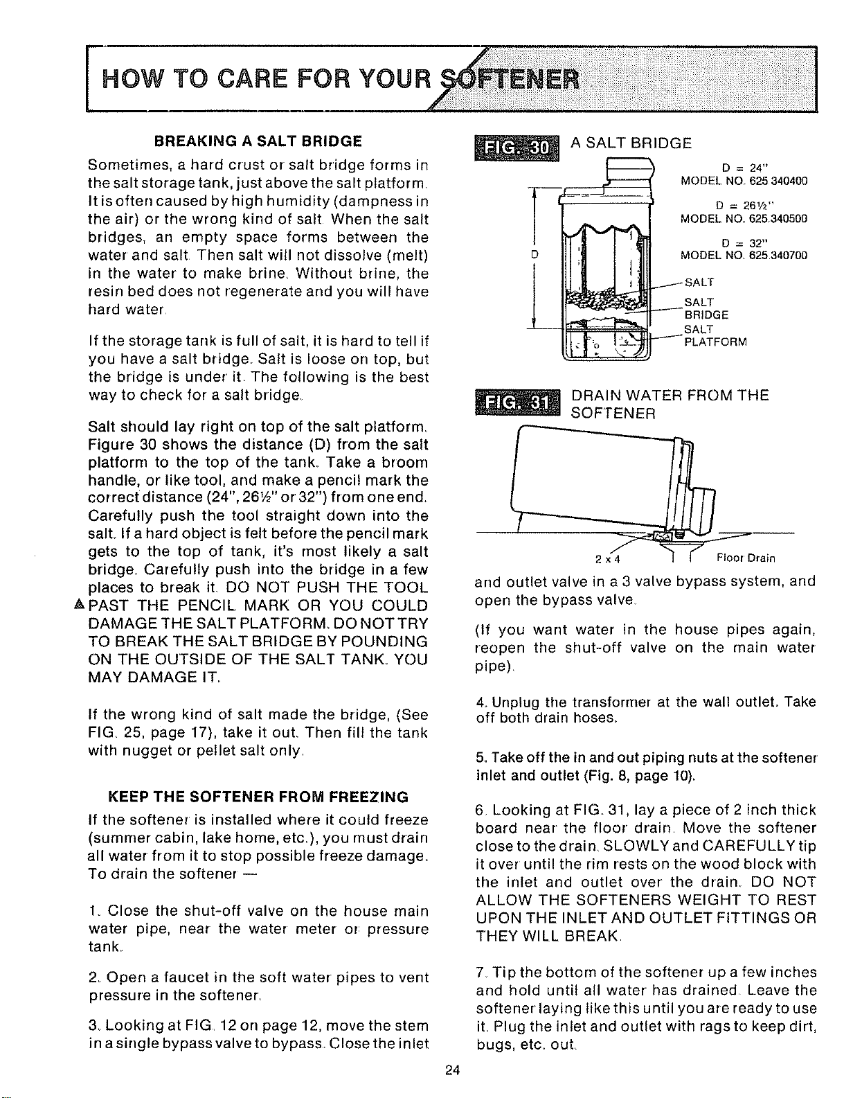
Salt should lay right on top of the salt platform
Figure 30 shows the distance (D) from the salt
platform to the top of the tank_ Take a broom
handle, or like tool, and make a pencil mark the
correct distance (24", 261/2'' or 32") from one end.
Carefully push the tool straight down into the
sail If a hard object is felt before the pencil mark
gets to the top of tank, it's most likely a salt
bridge_ Carefully push into the bridge in a few
places to break it DO NOT PUSH THE TOOL
APAST THE PENCIL MARK OR YOU COULD
DAMAGE THE SALT PLATFORM. DO NOT TRY
TO BREAK THE SALT BRIDGE BY POUNDING
ON THE OUTSIDE OF THE SALT TANK. YOU
MAY DAMAGE IT..
If the wrong kind of salt made the bridge, (See
FIG. 25, page 17), take it out Then fill the tank
with nugget or pellet salt only
KEEP THE SOFTENER FROM FREEZING
If the softener is installed where it could freeze
(summer cabin, lake home, etc ), you must drain
all water from it to stop possible freeze damage_
To drain the softener --
1. Close the shut-off valve on the house main
water pipe, near the water • meter or: pressure
tank.
2_ Open a faucet in the soft water pipes to vent
pressure in the softener.
3_ Looking at FIG. 12 on page 12, move the stem
in a single bypass valve to bypass• Close the inlet
1
D
l
A SALT BRIDGE
I
i o \ •
D = 24"
MODEL NO 625 340400
D = 261/2''
MODEL NO. 625340500
D = 32"
MODEL NO 625340700
t SALT
SALT
-----BRIDGE
SALT
"-'-_" PLATFORM
DRAIN WATER FROM THE
SOFTENER
2 x 4 _Drain
and outlet valve in a 3 valve bypass system, and
open the bypass valve
(If you want water in the house pipes again,
reopen the shut-off valve on the main water
pipe)
4o Unplug the transformer at the wall outleL Take
off both drain hoses_
5, Take off the in and out piping nuts at the softener
inlet and outlet (Fig. 8, page 10)_
6 Looking at FIG. 31, lay a piece of 2 inch thick
board near the floor drain Move the softener
close to the drain. SLOWLY and CAREFULLY tip
it over until the rim rests on the wood block with
the inlet and outlet over the drain_ DO NOT
ALLOW THE SOFTENERS WEIGHT TO REST
UPON THE INLET AND OUTLET FITTINGS OR
THEY WILL BREAK
7 Tip the bottom of the softener up a few inches
and hold untilallwater • has drained Leave the
softener laying like this until you are ready to use
it Plug the inlet and outlet with ragsto keep dirt,
bugs, etc_ ouL
24
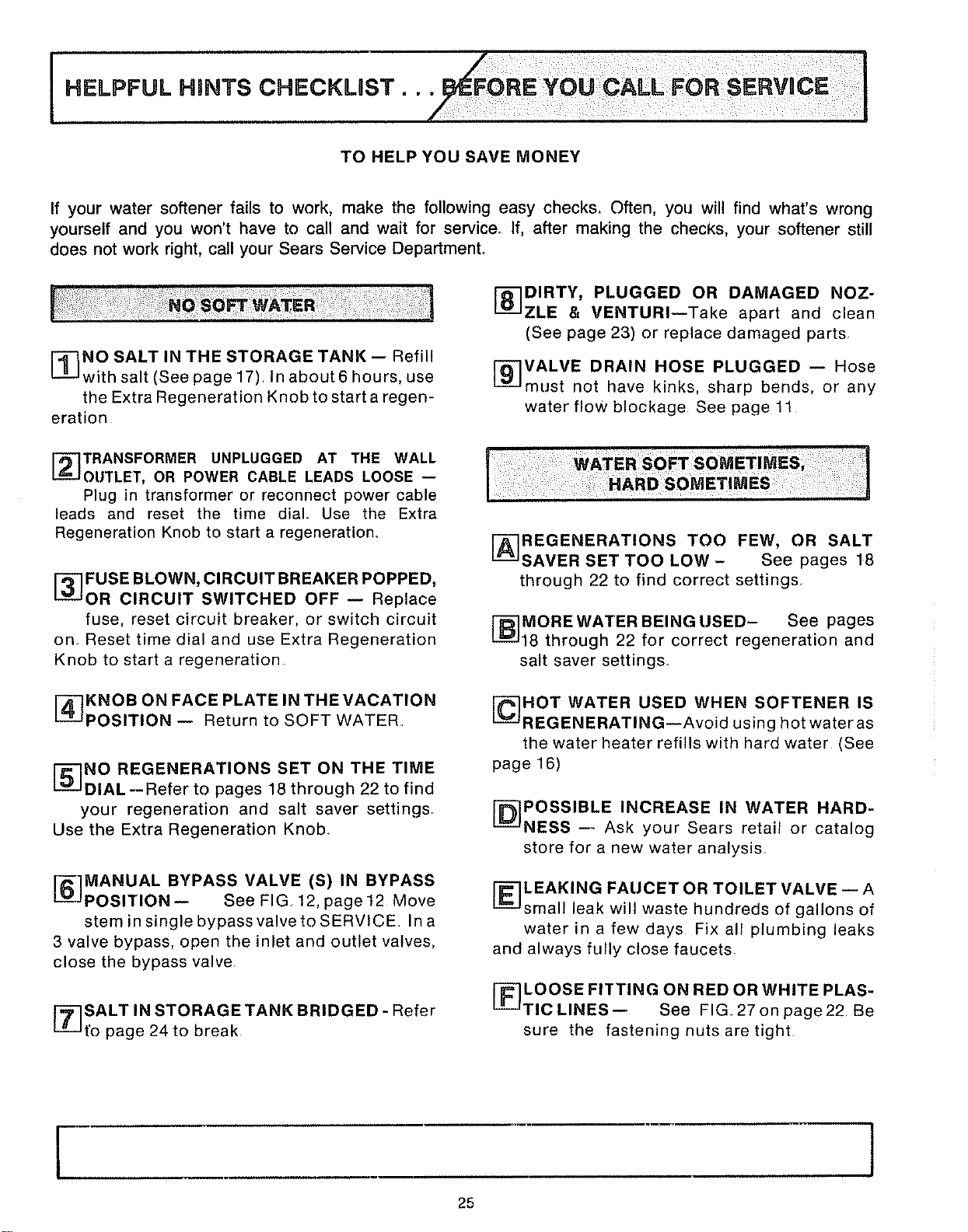
If your water softener fails to work, make the following easy checks° Often, you will find what's wrong
yourself and you won't have to call and wait for service. If, after making the checks, your softener still
does not work right, call your Sears Service Department°
[_NO SALT IN THE STORAGE TANK-- Refill
with salt (See page 17) In about6 hours, use
the Extra Regeneration Knob to start a regen-
eration
_8--IDIRTY, PLUGGED OR DAMAGED NOZ-
ZLE & VENTURI--Take apart and clean
(See page 23) or replace damaged parts
[-_VALVE DRAIN HOSE PLUGGED -- Hose
must not have kinks, sharp bends, or any
water flow blockage See page 11
I_TRANSFORMER UNPLUGGED AT THE WALL
OUTLET, OR POWER CABLE LEADS LOOSE --
Plug in transformer or reconnect power cable
leads and reset the time dial Use the Extra
Regeneration Knob to start a regeneration,
I_ FUSE BLOWN, CIRCUIT BREAKER POPPED,
OR CIRCUIT SWITCHED OFF -- Replace
fuse, reset circuit breaker, or switch circuit
on. Reset time dial and use Extra Regeneration
Knob to start a regeneration
[_KNOB ON FACE PLATE IN THE VACATION
POSITION-- Return to SOFT WATER
[_NO REGENERATIONS SET ON THE TIME
DIAL --Refer to pages 18 through 22 to find
your regeneration and salt saver settings,
Use the Extra Regeneration Knob_
I_MANUAL BYPASS VALVE (S) IN BYPASS
POSITION-- See FIG, 12, page12 Move
stem in single bypass valve to SERVICE Ina
3 valve bypass, open the inlet and outlet valves,
close the bypass valve.
_]SALT IN STORAGE TANK BRIDGED - Refer
t'o page 24 to break
[_REGENERATIONS TOO FEW, OR SALT
SAVER SET TOO LOW- See pages 18
through 22 to find correct settings
I-B] MORE WATER BEING USED- See pages
18 through 22 for correct regeneration and
salt saver settings.
C--]HOT WATER USED WHEN SOFTENER IS
REGENERATING--Avoid using hot water as
the water heater refills with hard water (See
page 16)
[-D-_POSSIBLE INCREASE IN WATER HARD-
NESS -- Ask your Sears retail or catalog
store for a new water analysis
[-_LEAKING FAUCET OR TOILET VALVE -- A
small leak will waste hundreds of gallons of
water inafewdays Fix all plumbing leaks
and always fully close faucets.
[_LOOSE FITTING ON RED OR WHITE PLAS-
TICLINES-- See FIG 27onpage22 Be
sure the fastening nuts are tight
r
25
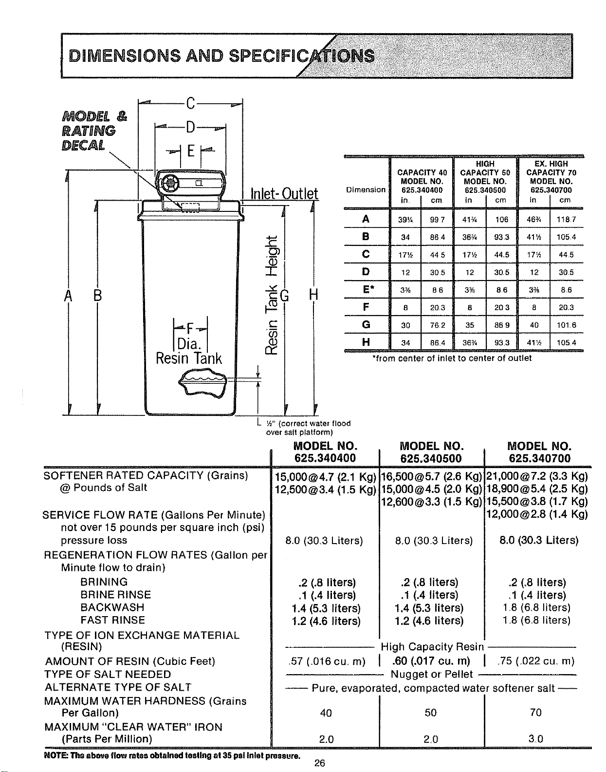
MODE[ &
RATnNG
DECAL
\
A B
r
Resi Dn[aT ank
_, €
SOFTENER RATED CAPACITY (Grains)
@ Pounds of Salt
Inlet-Outlet
T
H
c-
co
L ½" (correct water flood
over salt platform)
MODEL NO.
625.340400
CAPACITY 40
MODEL NO,
Dimension 625,340400
in I cm
,m
A 89'/, 98 7
B 34 86 4
C 17½ 445
D 12 305
E* 3% 8 6
F 8 203
G 30 762
H 34 86.4
*from
HIGH EX. HIGH
CAPACITY 50 CAPACITY 70
MODEL NO. MODEL NO.
625,340500 625.340700
in cm in I cm
41¾ 106 46¾ 1187
36¾ 933 41½ 1054
17V2 445 17½ 445
12 305 12 305
3% 86 3% 86
8 20 3 8 203
35 889 40 1016
36¾ 93.3 41½ 1054
center of inlet to center of outlet
SERVICE FLOW RATE (Gallons Per Minute)
not over 15 pounds per square inch (psi)
pressure loss
REGENERATION FLOW RATES (Gallon per
Minute flow to drain)
BRINING
BRINE RINSE
BACKWASH
FAST RINSE
TYPE OF ION EXCHANGE MATERIAL
(RESIN)
AMOUNT OF RESIN (Cubic Feet)
TYPE OF SALT NEEDED
ALTERNATE TYPE OF SALT
MAXIMUM WATER HARDNESS (Grains
Per Gallon)
MAXIMUM "CLEAR WATER" IRON
.... !Parts Per Million)
NOT_"_ aboveI1_ rateaobtainedreeling at35pal Inlet presaure.
MODEL NO.
625.340500
MODEL NO.
625.340700
8,0 (30,3 Liters)
.2 (.8 liters)
_1(.4 liters)
1.4 (5.3 liters)
1.2 (4.6 liters)
8,0 (30.3 Liters)
.2 (.8 liters)
.1 (.4 liters)
1,4 (5.3 liters)
1.2 (4.6 liters)
8.0 (30.3 Liters)
o2 (.8 liters)
.1 (.4 liters)
1,8 (6.8 liters)
18 (6,8 liters)
High Capacity Resin
_57 (,016cue m) I .60 (.017 cu. m) I _75 (.022 cu. m)
Nugget or Pellet
-- Pure, evaporated, compacted water softener salt --
=
40 I 50 70
2.0 I 2,0 3.0
26
L
6_
12
See
A.u,tlc
!
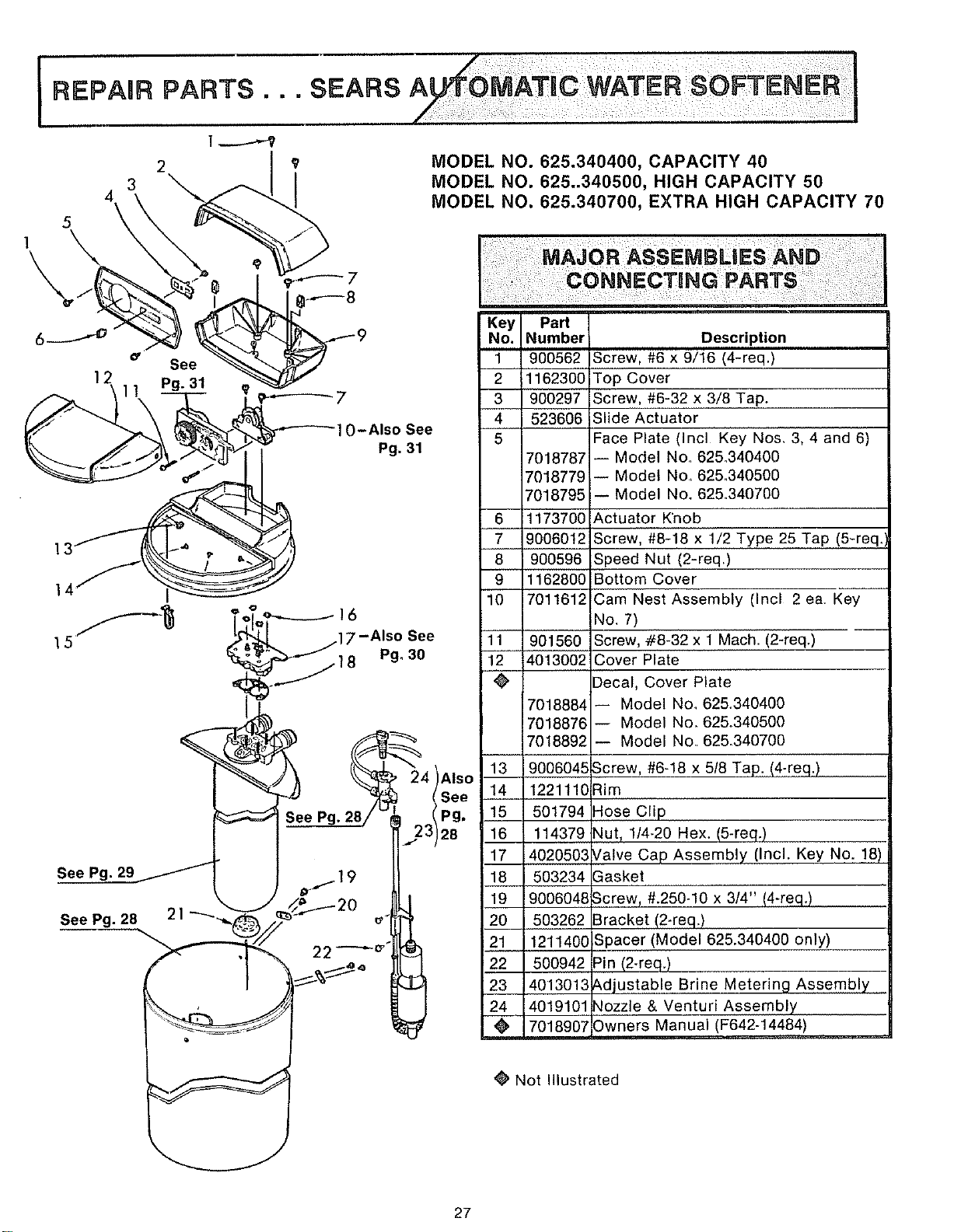
SEARS
MODEL NO. 625.340400, CAPACITY 40
MODEL NO. 625-340500, HIGH CAPACITY 50
MODEL NO. 625.340700, EXTRA HIGH CAPACITY 70
-Also See
Pg. 31
7-Also See
Pg. 30
Key PaN
No. Number
1 900562
2 1162300
3 900297
4 523606
5
6
7
8
9
10
7018787
_018779
7018795
1173700
9006012
900596
1162800
7011612
11 901560
12 4013002
÷
7O18884
7018876
7018892
Description
Screw, #6 x 9/16 (4-req.)
Top Cover
Screw, #6-32 x 3/8 Tap.
Slide Actuator
Face Plate (Incl Key Nos, 3, 4 and 6)
-- Model No. 625_340400
-- Model No, 625.,340500
-- Model No. 625.340700
Actuator Knob
Screw, #8-18 x 1/2 Type 25 Tap (5-req.
Speed Nut (2-req.)
Bottom Cover
Cam Nest Assembly (Incl 2 ea Key
No. 7)
Screw, #8-32 x 1 Mach. (2-req.)
Cover Plate
Decal, Cover Plate
-- Model No_ 625.340400
-- Model No_ 625°340500
-- Model No. 625.340700
See Pg. 29
See Pg. 28 21
13 9006045
14 122111G
15 501794
16 114379
17 4020503
18 503234
19 9006048
20 503262
21 121140C
22 500942
23 4013013
24 4019101
@' 7018907
Screw, #6-18 x 5/8 Tap. (4-req.)
Rim
Hose Clip
Nut, 1/4-20 Hex. (5-req.)
/alve Cap Assembly (Incl. Key No. 18)
Gasket
Screw, #.250_10 x 3/4" (4-req.)
Bracket (2-req.)
Spacer (Model 625.340400 only)
_in (2-req.)
_,djustable Brine Metering Assembly
qozzle & Venturi Assembly
Dwners Manual (F642-14484)
Not Illustrated
27
REPAUR PARTS
69
51
52
\
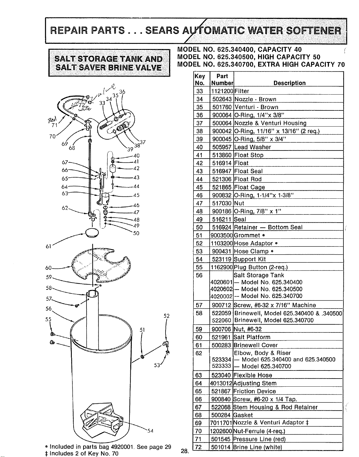
• Included in parts bag 4920001_ See page 29
:1:Includes 2 of Key No. 70
28°
Key Part
No. Number Description
33 1121200 Filter
34 502643 Nozzle - Brown
35 501760 Venturi. Brown
36 900064 O-Rirrg_ 1/4"x 3/8"
37 500064 Nozzle & Venturi Housing
38 900042 O-Ring_ 11/16" x 13/16" (2 req.)
39 900045 O-Ring, 5/8" x 3/4"
40 505957 Lead Washer
41 513860 Float Stop
42 516914 Float
43 516947 Float Seal
44 521306 Float Rod
45 521865 Float Cage
46 900832 O-Ring_ 1-1/4"x 1.3/8"
47 517030 Nut
48 900186 O-Ring_ 7/8" x 1"
49 516211 ;eal
50 516924 Retainer = Bottom Seal
51 9003500 Grommet •
52 1103200 Hose Adaptor o
53 900431 Hose Clamp =
54 523119 Support Kit
55 1162900 Plug Button (2-req.)
56 Salt Storage Tank
4020601 -- Model Noo 625.340400
4020602 -- Model No. 625.340500
4020002 -- Model No. 625.340700
57 900712 Screw_ #6-32 x 7/16" Machine
58 522059 Brinewell, Model 625°340400 & ,340500
522060 Brinewell, Model 625.340700
59 900706 Nut T#6-32
60 521961 Salt Platform
61 500283 Brinewell Cover
62 Elbow, Body & Riser
523334 -- Model 625340400 and 625.340500
523333 -- Model 625.340700
63 523040 =lexible Hose
64 401301; _.djusting Stem
65 521867 =riction Device
66 900840 Scre% #6-20 x 1/4 Tap.
67 522068 Stem Housing & Rod Retainer
68 500284 3asket
69 7011701 _lozzle & Venturi Adaptor:l:
70 120260C _lut-Ferrule (4-req.)
71 501545 =ressure Line (red)
72 501014 3fine Line (white)
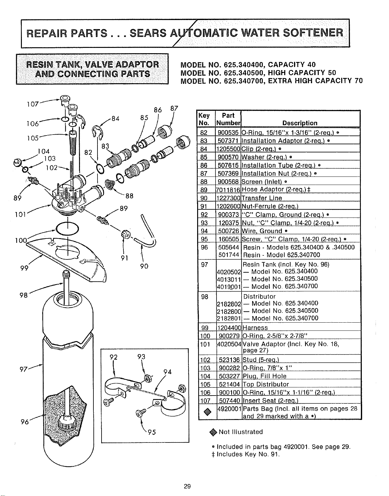
I Z¢oM BoWATE.SO TE.E.i/
REPAUR PARTS.. oSEARS
MODEL NO. 625.340400, CAPACITY 40
MODEL NO. 625.340500, HIGH CAPACITY 50
MODEL NO. 625.340700, EXTRA HIGH CAPACITY 70
89
101
99
98
88
j89
86 87
85
90
92 93
Key Pad
No. Numbem
82 900535
83 507371
84 1205560
85 900570
86 507615
87 507369
88 900568
89 7011816
90 122730C
91 120260C
92 900373
93 120375
94 500726
95 160505
96 505644
501744
_97
98
¢02050_
¢013011
d019_001
2182802:
2182800
2182801
99 1204400
100 900279
101 4020504
102 523136
103 900282
104 503227
105 521404
106 900100
107 507440
_ 4920001
Description
O-Ring, 15/16"x 1-3/16" (2-req.) o
Installation Adaptor (2-req.) •
Clip (2-req.) •
Washer (2-req.) •
Installation Tube (2-req.) =
Installation Nut (2-req.) o
Screen (Inlet) o
Hose Adaptor (2-req.) $
Transfer Line
Nut-Ferrule (2-req.)
"C" Clamp, Ground (2-req.) o
Nut, "C" Clamp, 1/4-20 (2-req.) =
Wire, Ground =
Screw, "C" Clamp, 1/4-20 (2-req.) •
i Resin - Models 625.340400 & .340500
Resin - Model 625.340700
Resin Tank (Incl. Key No. 96)
-- Model No. 625.340400
-- Model No.. 625.340500
-- Model No 62&340700
Distributor
-- Model No. 625340400
-- Model No. 625340500
-- Model No. 625.340700
Harness
O-Ring, 2-5/8"x 2-7/8"
Valve Adaptor (Incl. Key No. 18,
page 27)
Stud (5-req.)
O-Ring, 7/8"x 1"
Pluq, Fill Hole
Top Distributor
O-Ring, 15/16"x 1-1/16" (2-req.)
Insert Seat (2-req.)
Parts Bag (Inclo all items on pages 28
and 29 marked with a o)
Not Illustrated
• Included in parts bag 4920001_ See page 29.
:_Includes Key No. 91_
29
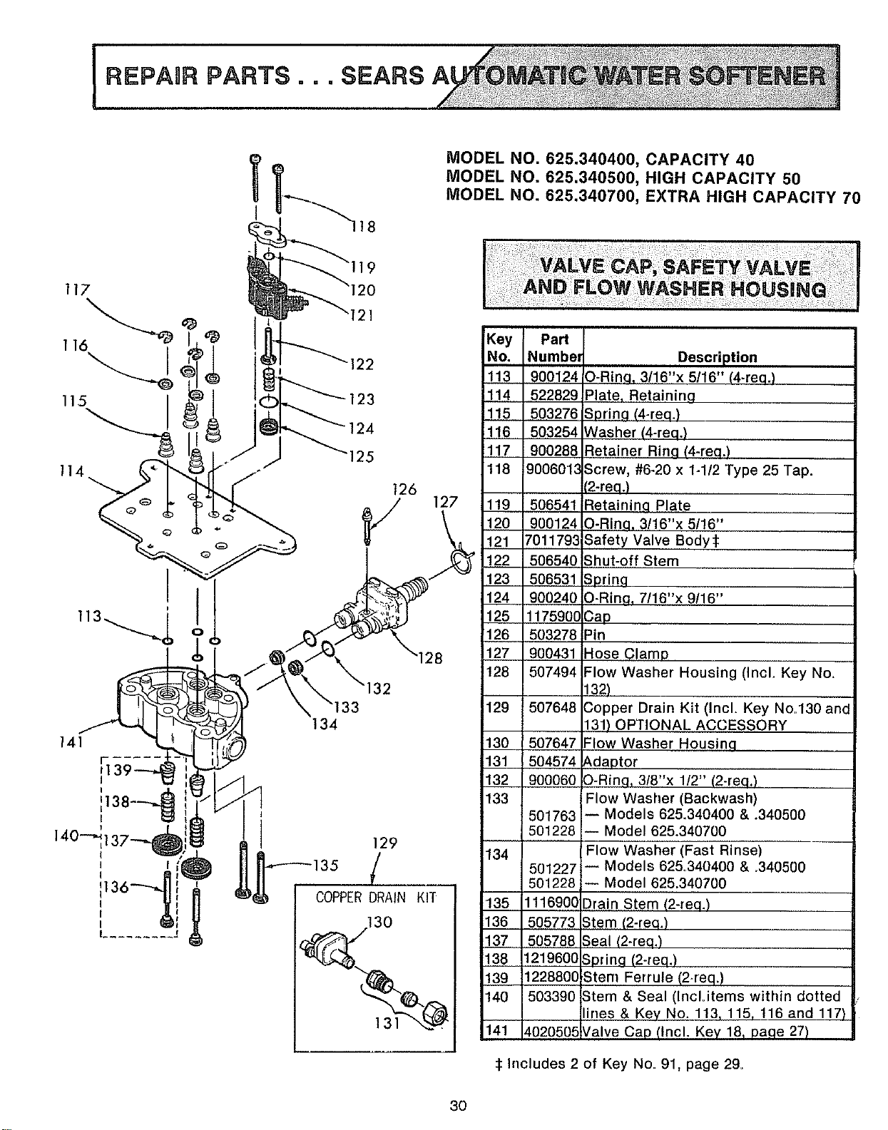
REPAaR ;
I
MODEL NO. 625.340400, CAPACITY 40
MODEL NO. 625.340500, HIGH CAPACITY 50
MODEL NO. 625.340700, EXTRA HIGH CAPACITY 70
11,4
141
I
I
I
"121
Key Pad
_122 No. Numbel
113 900124
123 114 522829
115 503276
124 116 503254
5 117 900288
118 9006013
126
V 127 119 506541
120 900124
121 7011793
122 506540
123 506531
124 900240
125 1175900
126 503278
127 900431
128 507494
134
129
COPPER DRAIN KIT
130
129 507648
130 507647
131 504574
132 900060
133
134
1501763
501228
501227
501228
135 1116900
136 505773
137 505788
138 1219600
139 1228800
140 503390
141 ¢020505
Description
O-Rinq, 3/16"x 5/16" (4-req.)
Plate, Retaining
Spring (4-req.)
Washer (4-req.)
Retainer Rinq (4-req.)
Screw, #6-20 x 1-1/2 Type 25 Tap.
(2-req.)
Retaininq Plate
O-Rin.q, 3/16"x 5/16"
Safety Valve Body:_
Shut-off Stem
Spring
O-Ring, 7/16"x 9/16"
Cap
Pin
Hose Clamp
Flow Washer Housing (Incl. Key No.
132)
Copper Drain Kit (Incl. Key No.130 and
131) OPTIONAL ACCESSORY
Flow Washer Housing
Adaptor
O-Ring, 3/8"x 1/2" (2-req.)
Flow Washer (Backwash)
-- Models 625.340400 & .340500
-- Model 625.340700
Flow Washer (Fast Rinse)
-- Models 625.340400 & .340500
-- Model 625.340700
Drain Stem (2-req.)
Stem (2-req.)
Seal (2-req.)
Spring (2-req.)
Stem Ferrule (2-req.)
Stem & Seal (IncLitems within dotted
lines & Key No. 113, 115, 116 and 117)
Valve Cap (Incl. Key 18, paqe 27)
:1:Includes 2 of Key No. 91, page 29.
3O
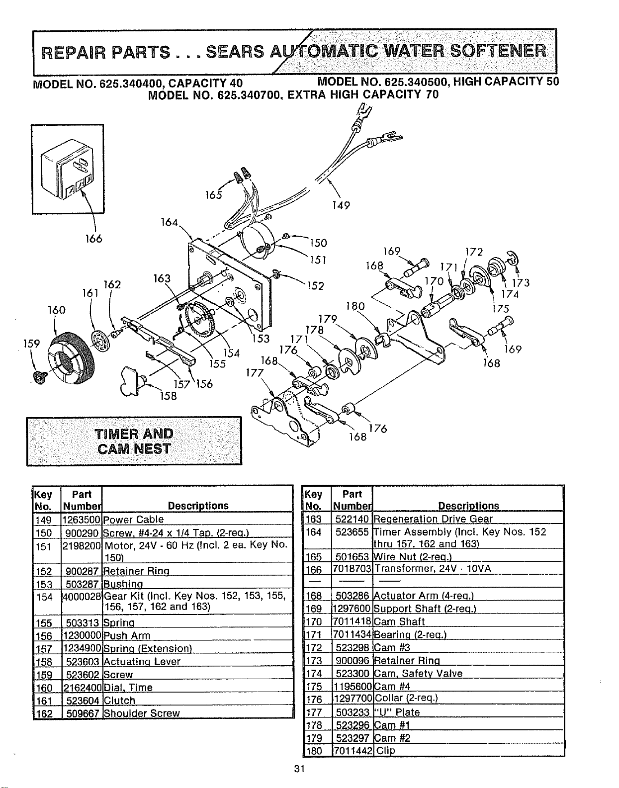
iii ii!i :i ili!i i!i!ii ii!i i!iiii ii i!! ill i iiii!i ii! i!i,i iiiii! i!i!i ii i ! iiii! :i ii iiiiiiii i i! i !i!iii i! i!ii ili!ii!i!i iiii i ii! ii!ii!i !i iiii !iii ii iiiii ii!iii! i ii
MODEL NO. 625.340400, CAPACITY 40 MODEL NO. 625.340500, HIGH CAPACITY 50
MODEL NO. 625.340700, EXTRA HIGH CAPACITY 70
166
162
161
160
164
163
165
149
169 172
168 171
173
174
175
159
168
169
168176
Key
No.
149
150
151
152
153
154
155
156
157
158
159
160
161
162
Part
Number
1263500
900290
2198200
900287
503287
4000028
503313
1230000
1234900
523603
523602
216240C
523604
509667
Key Part
Descriptions No. Numbm
)ower Cable 163 522140
Screw, #4-24 x 1/4 Tap. (2-req.) 164 523655
Motor, 24V - 60 Hz (IncL 2 ea. Key No.
150} 165 501653
Retainer Rinq 166 701870;
Bushinq --
Gear Kit (Incl. Key Nos. 152, 153, 155, 168 503286
156, 157, 162 and 163) 169 1297600
Sprinq 170 7011418
Push Arm 171 7011434
Sprinfl (Extension) 172 523298
Actuatinq Lever 173 900096
Screw 174 523300
Dial, Time 175 1195600
]lutch 176 1297700
_houlder Screw 177 503233
178 523296
179 523297
180 7011442
31
Descriptions
:_eqeneration Drive Gear
[imer Assembly (Inclo Key Nos. 152
:hru 157, 162 and 163}
Nire Nut (2-req.)
Transformer, 24V _10VA
_ctuator Arm (4-req.)
Support Shaft (2-req.)
3am Shaft
3earinq (2-req.)
3am #3
%tainer Rinq
3am, Safety Valve
3am #4
Collar (2-req.)
'U" Plate
3am #1
3am #2
Clip
Now that you have purchased your water softener, should a
need ever exist for repair parts or service, simply contact any
SearsServiceCenter.Besureto provideall pertinent facts when
you call or visit
The model number of your water softener is found on the rating
decal. This decal is on the inside, front of the storage tank rim.
WHEN ORDERING REPAIR PARTS, ALWAYS GIVE THE
FOLLOWING INFORMATION:
--PART NUMBER
--MODEL NUMBER
--PART DESCRIPTION
--NAME OF ITEM
All parts listed may be ordered from any Sears Service Center.
If the parts you need are not stocked locally, your order will be
electronically transmitted to a Sears Repair Parts Distribution
center for handling.
When Sears arranges the installation, you can be sure the job is
done right. We will arrange for professional workmanship...and
we'll take care of the entire project. What's more, during installa-
tion you get insured protectiono..against property darnage and
also against accidents to workmen. All you have to do is talk to
your Sears salesperson or call your nearest Sears store today for
detailed inforrnation.
F642-14484 7018907 (11/84)