Loading ...
Loading ...
Loading ...
12
Majestic • QUARTZ32, QUARTZ36 Owner’s Manual • 2412-981 Rev. E • 8/16
G. Appliance Break-In
Initial Break-in Procedure
• The fireplace should be run three to four hours
continuously on high.
• Turn the fi replace off and allow it to completely cool.
• Remove fi xed glass assembly. See Section 4.B.
• Clean fi xed glass assembly. See Section 4.
• Replace the fi xed glass assembly and run continuously
on high an additional 12 hours.
This cures the materials used to manufacture the fi re-
place.
NOTICE! Open windows for air circulation during fi re-
place break-in.
• Some people may be sensitive to smoke and odors.
• Smoke detectors may activate.
H. Heat Management
Heat Output
The QUARTZ32 and QUARTZ36 models have a variable
burn rate which is controlled by the HI/LO knob on the gas
valve. Therefore the fl ame height is adjustable. The HI/
LO knob is shown in Figure 3.5. It is located in the control
cavity of the appliance. The HI/LO knob may be adjusted
as desired by turning counterclockwise to the HIGH
position and by turning clockwise to the LO position.
If an optional fan is installed, the fan speed is controlled
by adjusting the speed control knob. Turn the knob
clockwise to increase the fan speed and counterclockwise
to decrease the fan speed.
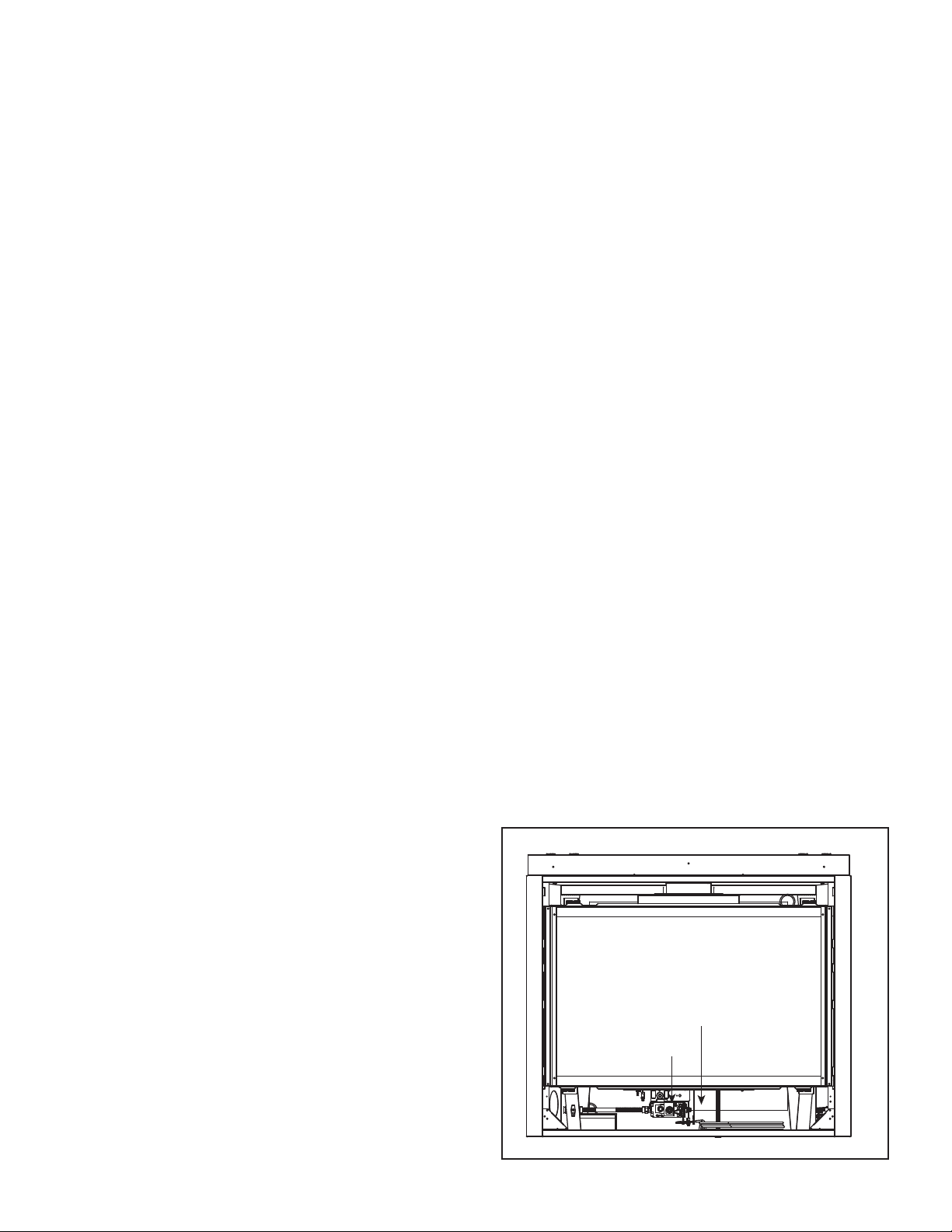
I. Operation During A Power Outage (IPI)
The IntelliFire intermittent pilot ignition system comes
with a battery backup system that enables the system
to operate in a power outage. A factory-installed battery
pack is located in the control cavity of the appliance. See
Figure 3.5. Batteries should not be placed in the battery
tray while using electrical power to operate the fi replace.
Remove batteries from battery tray when power has been
restored.
To Operate Fireplace Using Battery Power (DC):
1. Access the control cavity of the appliance. See Figure
3.5 for location. The decorative front or door may
need to be removed.
2. Locate the battery tray and insert two D cell batteries.
Battery polarity must be correct or module damage
will occur. See Figure 3.5. A complete wiring diagram
is included in the Electrical section of the appliance
Installation Manual.
NOTICE: Batteries should only be used as a power source
in the event of an emergency power outage. Batteries
should not be used as a primary long-term power source.
To Return to Operation Using Electrical (AC) Power
Standard Wall Switch or Factory-Installed ON/OFF
Switch:
• Toggle the switch to OFF and remove the batteries
from the battery tray. Replace door or decorative front
on appliance.
Multifunctional Wired Wall Switch Control System:
• Slide the switch to the OFF position. Remove the
batteries from the battery tray. Replace door or
decorative front on appliance.
Wireless Remote:
• Slide the ON/REMOTE/OFF switch to the REMOTE
position. Remove the batteries from the battery tray.
Replace decorative front on appliance.
NOTICE: Some functionality will be lost when using battery
backup including remote control, fan, lights, or any other
auxiliary functions that require household 110-120 VAC
power.
3. Turn the appliance on according to the instructions
below for the appropriate type of control:
Standard Wall Switch or Factory-Installed ON/OFF
Switch:
• Toggle the switch as you would under normal
circumstances.
Multifunctional Wired Wall Switch Control System:
• Locate the wired wall switch control module in control
cavity.
• Locate battery operation switch on the side of the
module.
• Slide the switch to the BATTERY ON or ON position.
Wireless Remote:
• Locate the remote control module in the control cavity.
• Slide the ON/REMOTE/OFF switch to the ON position.
Figure 3.5 Control Cavity - Generic Appliance Shown
CONTROL CAVITY
VALVE
Loading ...
Loading ...
Loading ...