For the Following Models
TI-1+1B TI-1+2B
TI-1+1GT TI-1+2GT
TI-2GT TI-3GT
COOKTOP MANUAL
Visit Us: www.TrueInduction.com
Call Us: 877-862-7049
IMPORTANT SAFETY INFORMATION
IMPORTANT: Before beginning installation please read these instructions completely and
carefully. Save for local gas and electrical inspector's use.
WARNING: If the information in this manual is not followed exactly, a fire or explosion, may result
causing property damage, personal injury, or death.
Do not store or use gasoline or other flammable vapors and liquids in the vicinity of this or any
other appliance.
WHAT TO DO IF YOU SMELL GAS:
• Do not try to light any appliance.
• Do not try to light any appliance.
• Do not touch any electrical switch.
• Do not use any phones in your building.
• Immediately call your gas supplier from a neighbor's phone. Follow the gas supplier's
instructions.
• If you cannot reach your gas supplier, call the fire department.
** Installation and service must be performed by a qualified installe
** Installation and service must be performed by a qualified installer, service agency, or
gas supplier.
WARNING: Gas leaks cannot always be detected by smell.
Gas suppliers and True Induction recommend that you use a gas detector approved by UL or
CSA. If a gas leak is detected, follow the 'What to do if you smell gas" instructions above.
IMPOR
IMPORTANT: This appliance is designed and manufactured solely for the cooking of domestic
(household) food and is not suitable for any non-domestic application and therefore CANNOT be
used in a commercial environment. The appliance guarantee will be void if the appliance is used
within a non-domestic environment. i.e. a semi-commercial, commercial or communal
environment.
W
WARNING: The appliance must be isolated from the gas supply piping system by closing its
individual manual shutoff valve during any pressure testing of the gas supply piping system at test
pressures equal to or less than 1 /2 psi (3.5 kPa).
SAVE THESE INSTRUCTIONS
IMPORTANT SAFETY INFORMATION
Continued
WARNING: To reduce the risk of fire, electrical shock, injury to persons, or damage when using
cooktop, follow basic precautions including the following:
WARNING: NEVER use this appliance as a space heater to heat or warm the room. Doing so
may result in carbon monoxide poisoning and overheating of the cooktop.
CAUTION: Keep out of reach of children. Children climbing on and/ or using the cooktop could
result in serious injury.
Proper installation:
•
• The cooktop, when installed, must be electrically grounded in accordance with local codes. Or, in
the absence of local codes, with the National Electrical Code, ANSI/NFPA70, or the Canadian
Electrical Code, Part 1, ensure the cooktop is properly installed and grounded by a qualified
technician.
• This cooktop may be equipped with a three-prong grounding plug for your protection against
shock hazard and should be plugged directly into a properly grounded receptacle. Do not cut off
or remove the grounding prong from this plug.
• Disconnect the electrical supply before servicing the cooktop.
• Disconnect the electrical supply before servicing the cooktop.
• Stepping, leaning, or sitting on the cooktop surface are not intended methods of use and may
result in injury to person(s) or property.
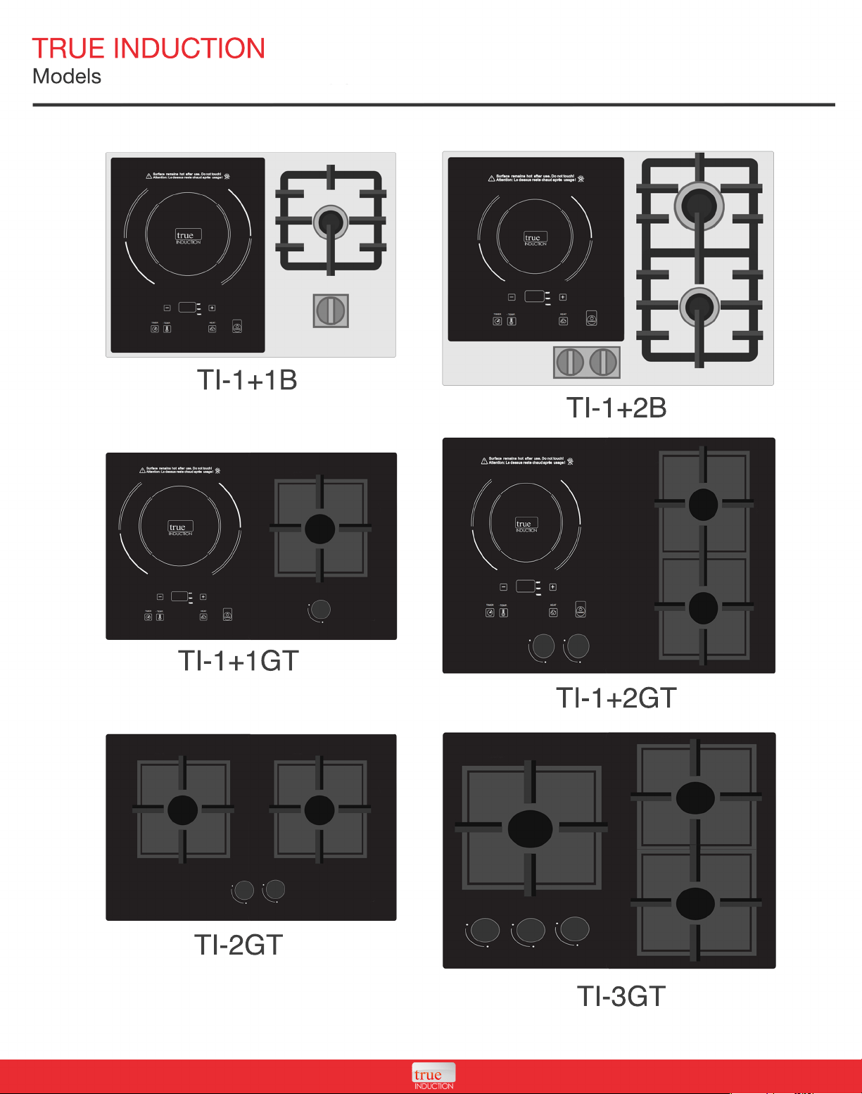
TRUE INDUCTION
Models
TI-1+1B
TI-1+2B
TI-1+1GT
TI-1+2GT
TI-2GT
TI-3GT
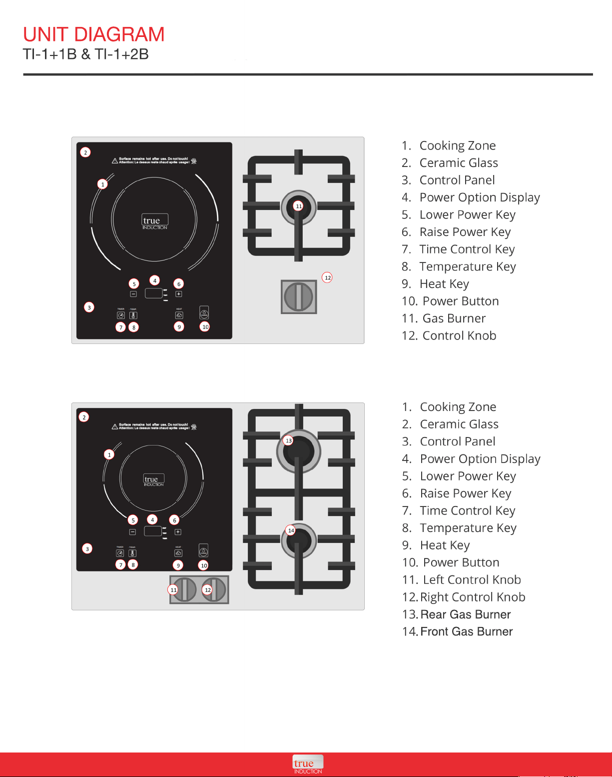
UNIT DIAGRAM
TI-1+1B & TI-1+2B
Rear Gas Burner
Front Gas Burner
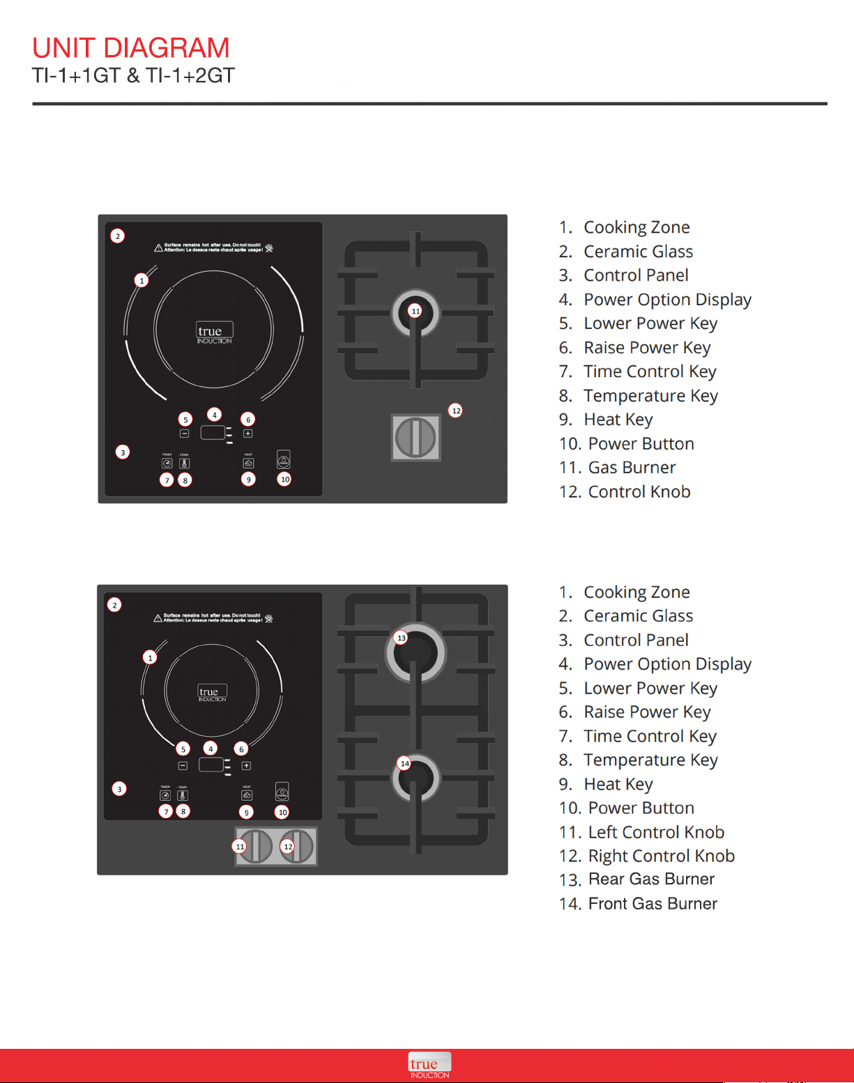
UNIT DIAGRAM
TI-1+1GT & TI-1+2GT
Rear Gas Burner
Front Gas Burner
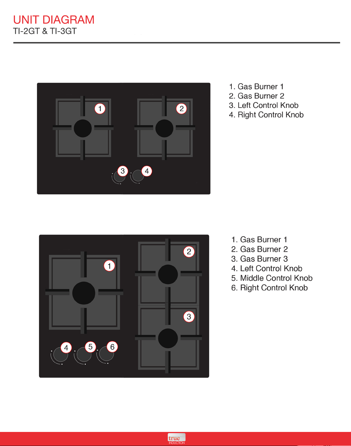
UNIT DIAGRAM
TI-2GT & TI-3GT
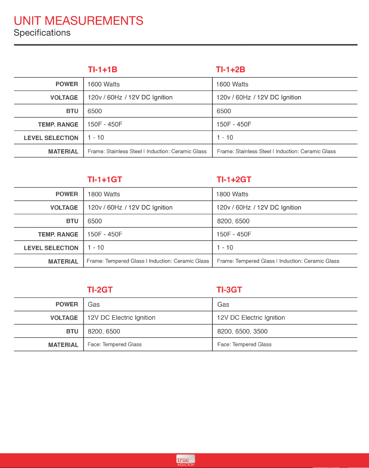
UNIT MEASUREMENTS
Specifications
/ 12V DC Ignition
/ 12V DC Ignition
/ 12V DC Ignition
/ 12V DC Ignition
INSTALLATION
Beginning Installation
• Installation and service must be conducted by qualified / licensed technician, in accordance with
national & local regulation. Failure to comply will void the product warranty.
• Always disconnect the appliance power before installation & maintenance.
• Shut off the main gas supply valve before disconnecting the old cooktop and leave it off until the
new hook-up has been completed. Don't forget to relight the pilot on other gas appliances when
you turn the gas back on.
• NEVER USE AN OLD CONNECTOR WHEN INSTALLING A NEW COOKTOP.
•
• This cooktop leaves the factory set for use with LP gas. Please read carefully in the rating label
information to confirm this.
• Your cooktop is designed for LP gas (propane or butane), 10" of water column.
• For proper operation, the pressure supplied must be between 10" and 13" of water column.
• When checking for proper operation of this regulator, the inlet pressure must be at least 1"
greater than the operating pressure as given above.
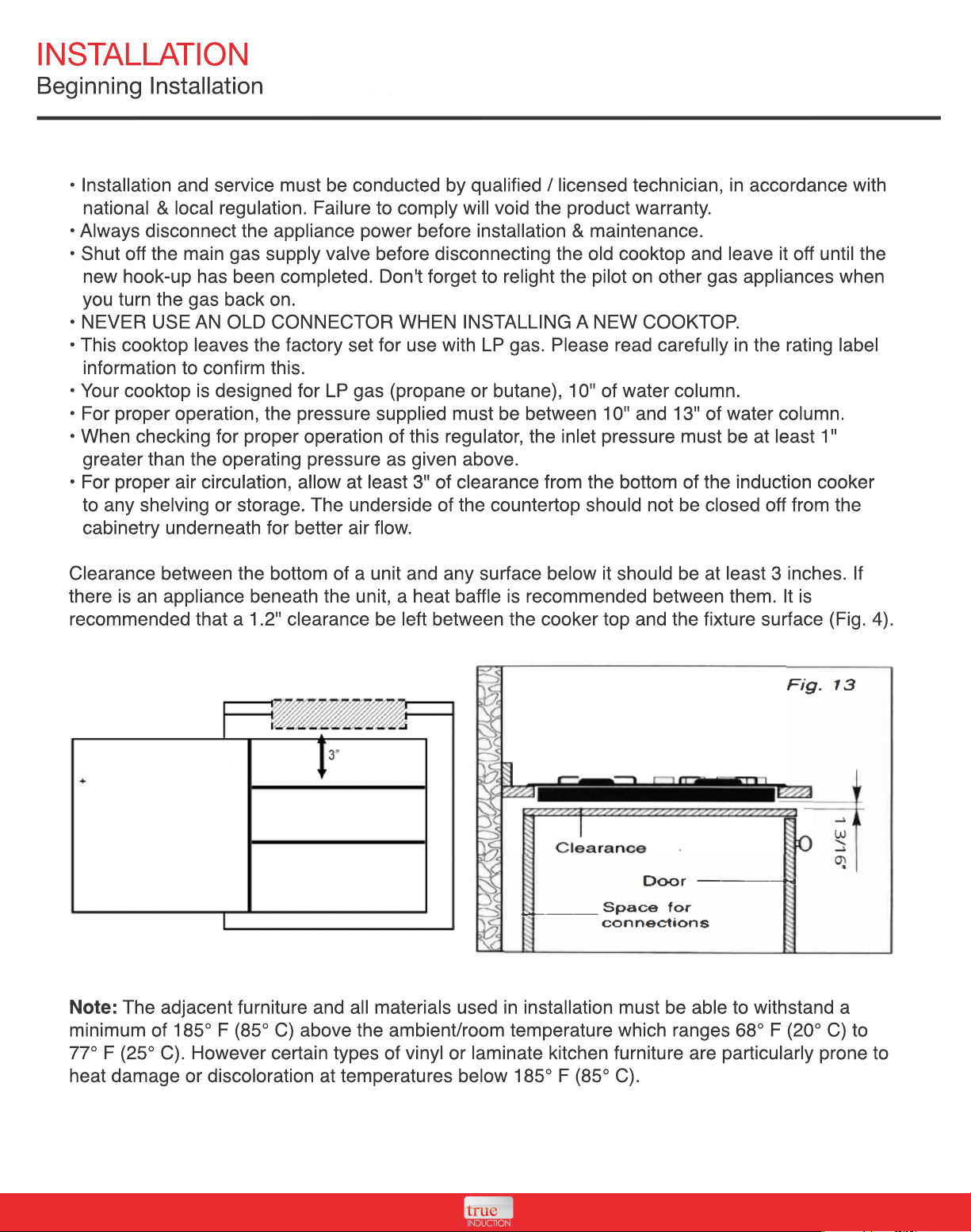
• For proper air circulation, allow at least 3" of clearance from the bottom of the induction cooker
• For proper air circulation, allow at least 3" of clearance from the bottom of the induction cooker
to any shelving or storage. The underside of the countertop should not be closed off from the
cabinetry underneath for better air flow.
Clearance between the bottom of a unit and any surface below it should be at least 3 inches. If
there is an appliance beneath the unit, a heat baffle is recommended between them. It is
recommended that a 1.2" clearance be left between the cooker top and the fixture surface (Fig. 4).
Note:
Note: The adjacent furniture and all materials used in installation must be able to withstand a
minimum of 185° F (85° C) above the ambient/room temperature which ranges 68° F (20° C) to
77° F (25° C). However certain types of vinyl or laminate kitchen furniture are particularly prone to
heat damage or discoloration at temperatures below 185° F (85° C).
INSTALLATION
Clearance for Cooktops
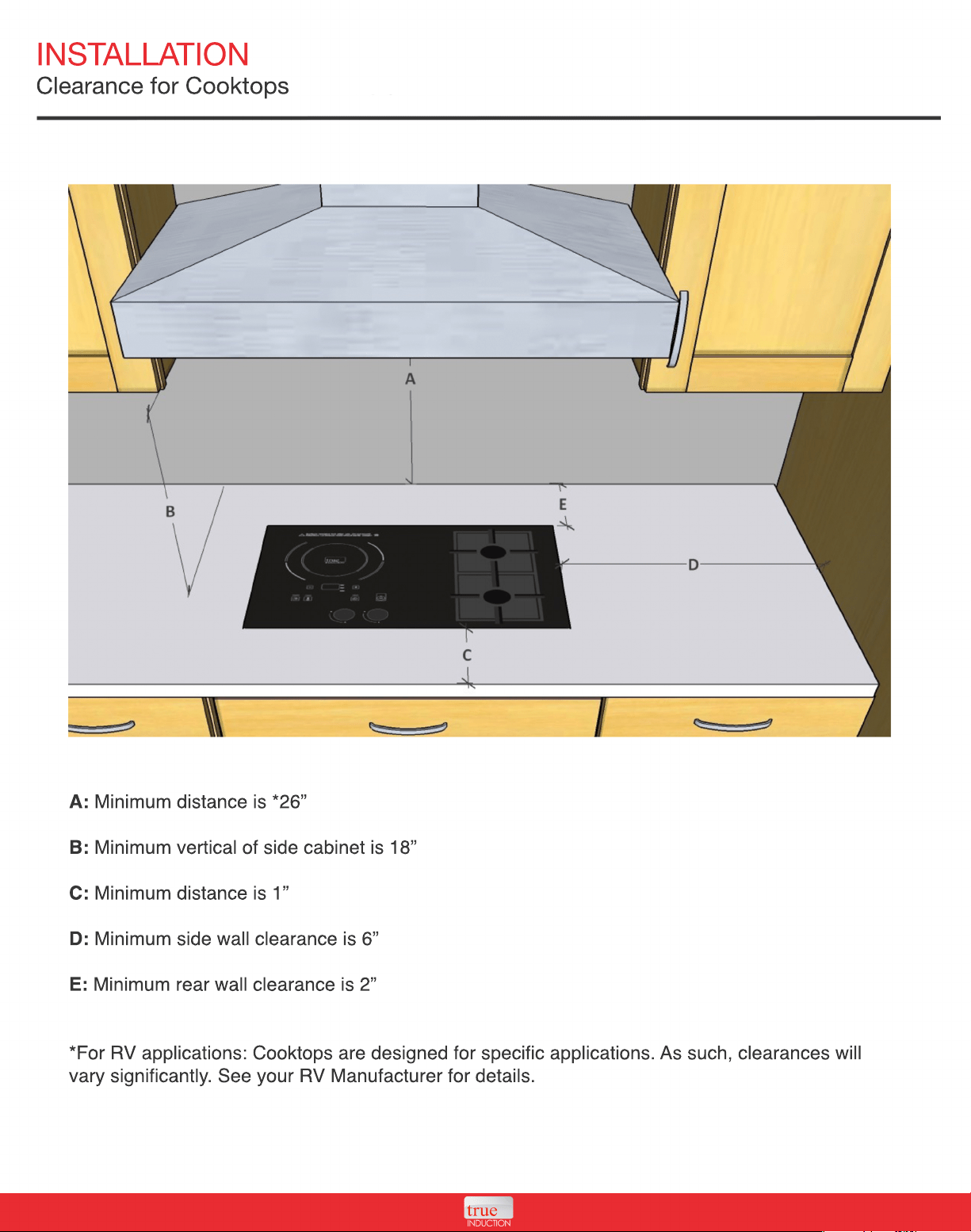
A: Minimum distance is *26”
B: Minimum vertical of side cabinet is 18”
C: Minimum distance is 1”
D: Minimum side wall clearance is 6”
E: Minimum rear wall clearance is 2”
*For
*For RV applications: Cooktops are designed for specific applications. As such, clearances will
vary significantly. See your RV Manufacturer for details.
INSTALLATION
Cutout Sizes
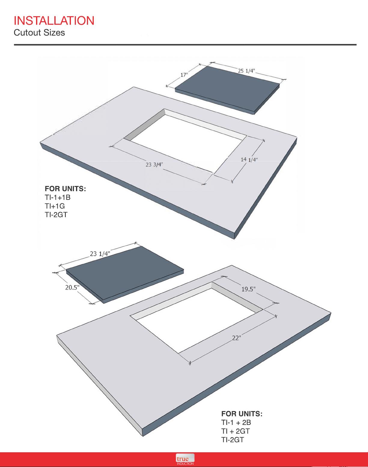
FOR UNITS:
TI-1+1B
TI+1G
TI-2GT
FOR UNITS:
TI-1 + 2B
TI + 2GT
TI-2GT
INSTALLATION
Fastening the Cooktop
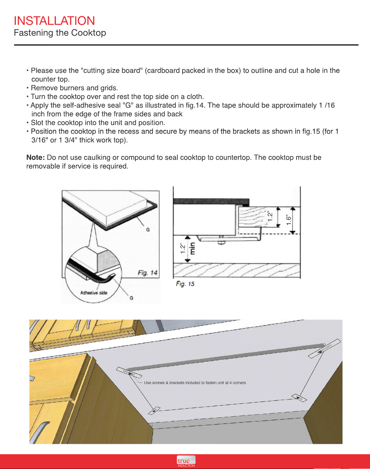
• Please use the "cutting size board" (cardboard packed in the box) to outline and cut a hole in the
counter top.
• Remove burners and grids.
• Turn the cooktop over and rest the top side on a cloth.
• Apply the self-adhesive seal "G" as illustrated in fig.14. The tape should be approximately 1 /16
inch from the edge of the frame sides and back
• Slot the cooktop into the unit and position.
• Position the cooktop in the recess and secure by means of the brackets as shown in fig.15 (for 1
• Position the cooktop in the recess and secure by means of the brackets as shown in fig.15 (for 1
3/16" or 1 3/4" thick work top).
Note: Do not use caulking or compound to seal cooktop to countertop. The cooktop must be
removable if service is required.
INSTALLATION
Connecting the Gas
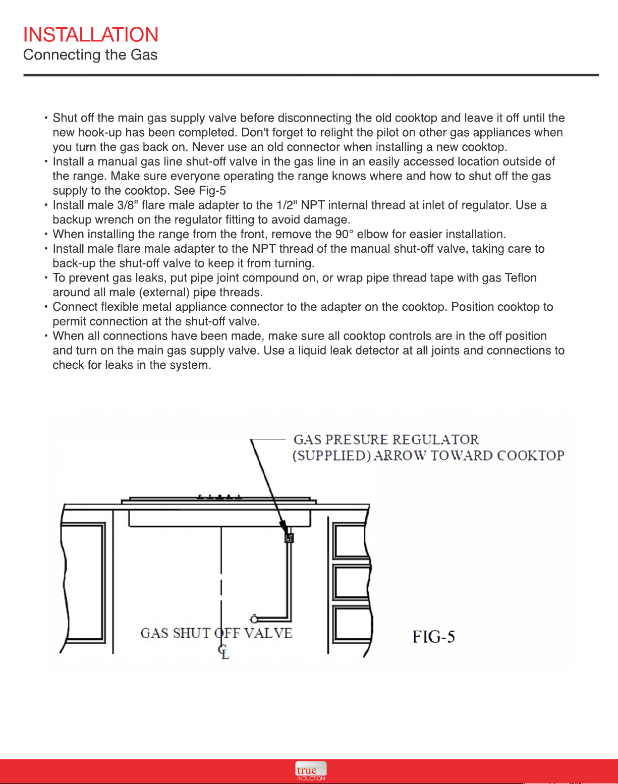
• Shut off the main gas supply valve before disconnecting the old cooktop and leave it off until the
new hook-up has been completed. Don't forget to relight the pilot on other gas appliances when
you turn the gas back on. Never use an old connector when installing a new cooktop.
• Install a manual gas line shut-off valve in the gas line in an easily accessed location outside of
the range. Make sure everyone operating the range knows where and how to shut off the gas
supply to the cooktop. See Fig-5
•
• Install male 3/8" flare male adapter to the 1/2" NPT internal thread at inlet of regulator. Use a
backup wrench on the regulator fitting to avoid damage.
• When installing the range from the front, remove the 90° elbow for easier installation.
• Install male flare male adapter to the NPT thread of the manual shut-off valve, taking care to
back-up the shut-off valve to keep it from turning.
• To prevent gas leaks, put pipe joint compound on, or wrap pipe thread tape with gas Teflon
around all male (external) pipe threads.
•
• Connect flexible metal appliance connector to the adapter on the cooktop. Position cooktop to
permit connection at the shut-off valve.
• When all connections have been made, make sure all cooktop controls are in the off position
and turn on the main gas supply valve. Use a liquid leak detector at all joints and connections to
check for leaks in the system.
INSTALLATION
Install Burner Heads
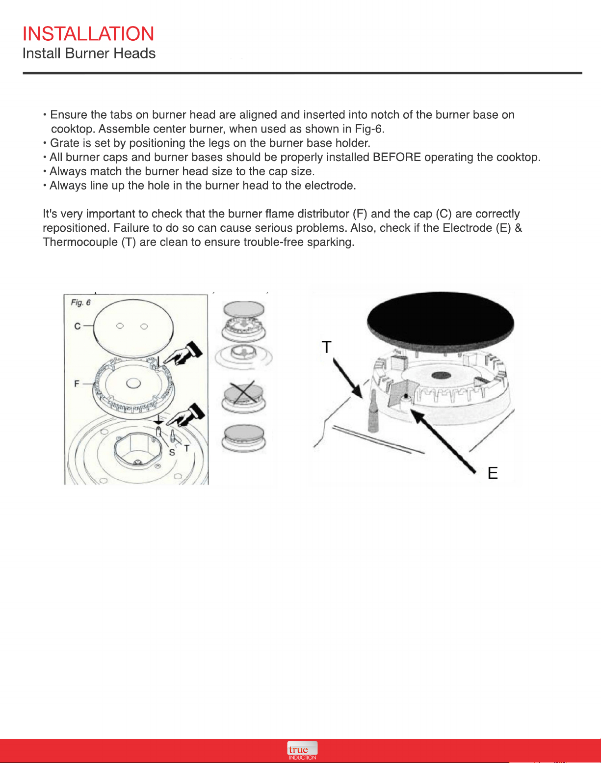
• Ensure the tabs on burner head are aligned and inserted into notch of the burner base on
cooktop. Assemble center burner, when used as shown in Fig-6.
• Grate is set by positioning the legs on the burner base holder.
• All burner caps and burner bases should be properly installed BEFORE operating the cooktop.
• Always match the burner head size to the cap size.
• Always line up the hole in the burner head to the electrode.
It's very important to check that the burner flame distributor (F) and the cap (C) are correctly
It's very important to check that the burner flame distributor (F) and the cap (C) are correctly
repositioned. Failure to do so can cause serious problems. Also, check if the Electrode (E) &
Thermocouple (T) are clean to ensure trouble-free sparking.
INSTALLATION
Unit Battery
Some units may feature a battery, low voltage connection, or electric adapter for the electric gas
igniter.
1.5 Volt Battery
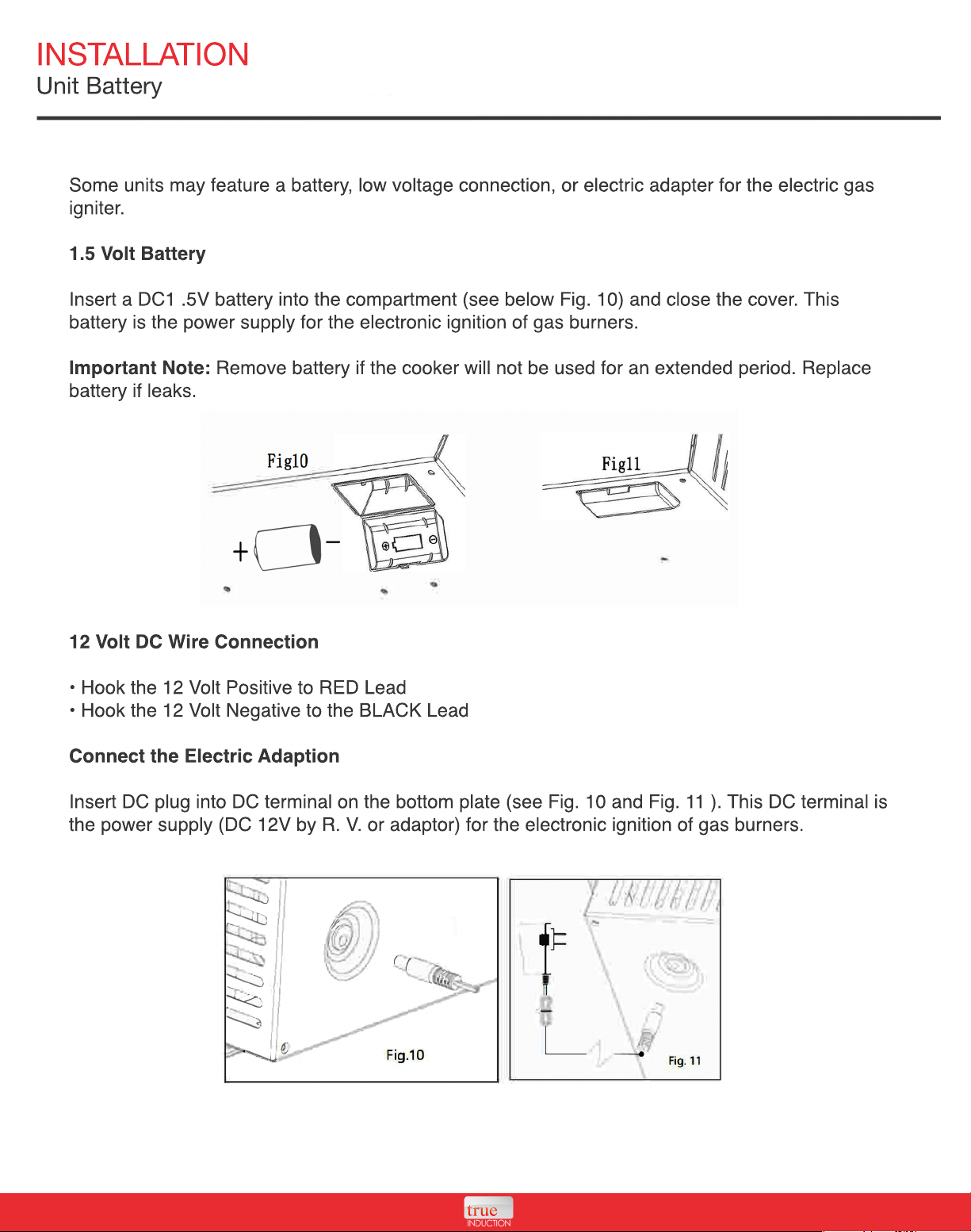
Insert a DC1 .5V battery into the compartment (see below Fig. 10) and close the cover. This
battery is the power supply for the electronic ignition of gas burners.
Important Note: Remove battery if the cooker will not be used for an extended period. Replace
battery if leaks.
12
12 Volt DC Wire Connection
• Hook the 12 Volt Positive to RED Lead
• Hook the 12 Volt Negative to the BLACK Lead
Connect the Electric Adaption
Insert DC plug into DC terminal on the bottom plate (see Fig. 10 and Fig. 11 ). This DC terminal is
the power supply (DC 12V by R. V. or adaptor) for the electronic ignition of gas burners.
INSTALLATION
Gas Information
Converting to LP Gas
This cooktop leaves the factory set for use with LP gas. Please read the rating label information
carefully to confirm this.
Provide Adequate Gas Supply
• Your cooktop is designed for LP gas (propane), 10" of water column.
• Make sure you are supplying your cooktop with the type of gas for which it's designed.
•
• For proper operation the pressure supplied must be between 10" and 13" of water column.
• When checking for proper operation of this regulator, the inlet pressure must be at least 1"
greater than the operating pressure as given above.`
• A flexible metal appliance connector used to connect the cooktop to the gas supply line should
have an I.D. of 1/2 inches and be 5 feet in length for ease of installation. In Canada, flexible
connectors must be single wall metal connectors no longer than 6 feet in length.
T
To prevent gas leaks, put pipe joint compound on, or wrap pipe thread tape with Teflon around all
male (external) pipe threads.
• Install a manual gas line shut-off valve in the gas line in an easily accessed location outside of
the range. Make sure everyone operating the range knows where and how to shut off the gas
supply to the cooktop. See Fig-5
• Install male 3/8" flare male adapter to the 1/2" NPT internal thread at inlet of regulator. Use a
backup wrench on the regulator fitting to avoid damage.
•
• When installing the range from the front, remove the 90° elbow for easier installation.
• Install male flare male adapter to the NPT internal thread of the manual shut-off valve, taking
care to back-up the shut-off valve to keep it from turning.
• Connect flexible metal appliance connector to the adapter on the cooktop. Position cooktop to
permit connection at the shut-off valve.
•
• When all connections have been made, make sure all cooktop controls are in the off position
and turn on the main gas supply valve. Use a liquid leak detector at all joints and connections to
check for leaks in the system.
WARNING - FIRE HAZARD: DO NOT use a flame to check for gas leaks.
INSTALLATION
Gas Information
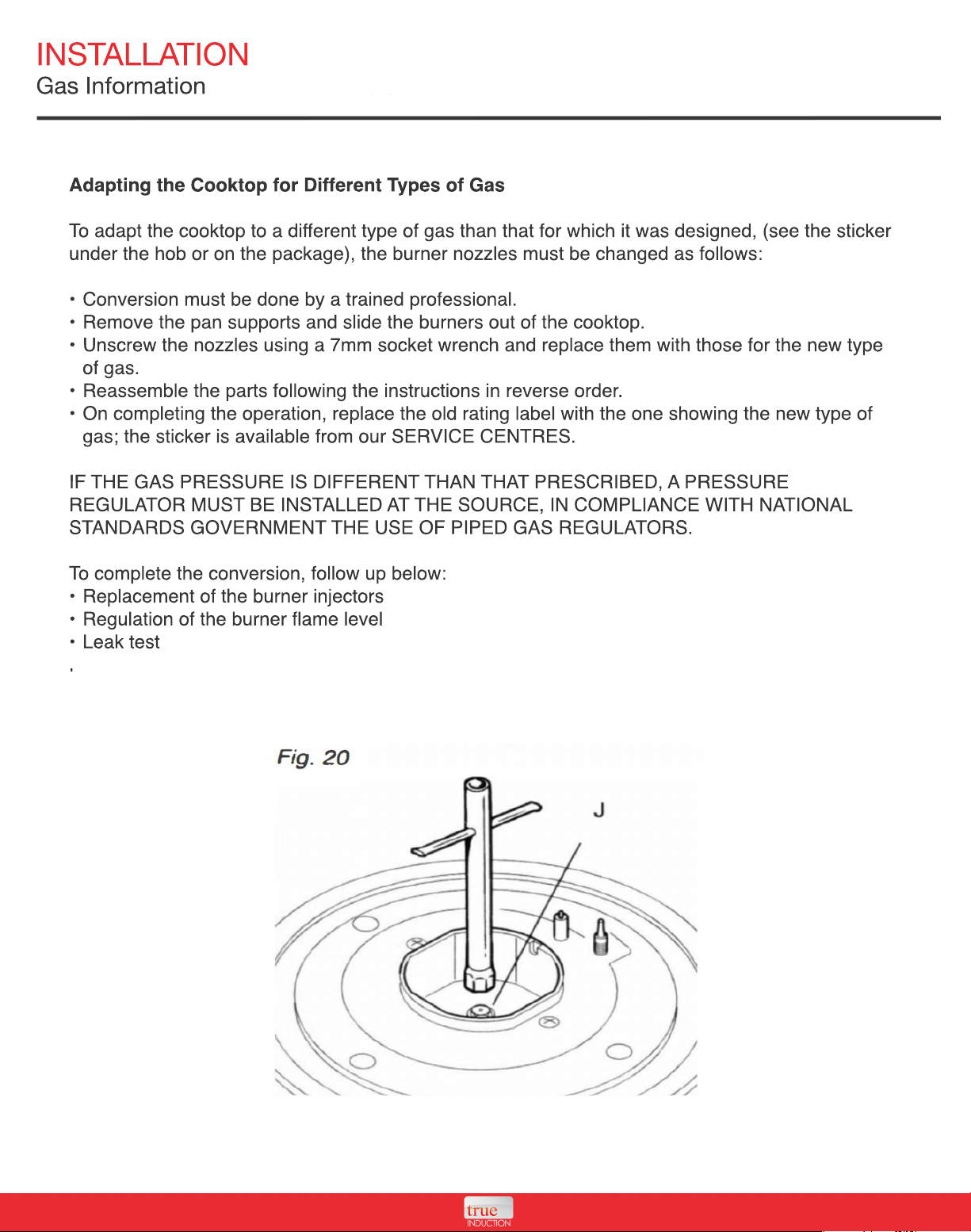
Adapting the Cooktop for Different Types of Gas
To adapt the cooktop to a different type of gas than that for which it was designed, (see the sticker
under the hob or on the package), the burner nozzles must be changed as follows:
• Conversion must be done by a trained professional.
• Remove the pan supports and slide the burners out of the cooktop.
•
• Unscrew the nozzles using a 7mm socket wrench and replace them with those for the new type
of gas.
• Reassemble the parts following the instructions in reverse order.
• On completing the operation, replace the old rating label with the one showing the new type of
gas; the sticker is available from our SERVICE CENTRES.
IF
IF THE GAS PRESSURE IS DIFFERENT THAN THAT PRESCRIBED, A PRESSURE
REGULATOR MUST BE INSTALLED AT THE SOURCE, IN COMPLIANCE WITH NATIONAL
STANDARDS GOVERNMENT THE USE OF PIPED GAS REGULATORS.
To complete the conversion, follow up below:
• Replacement of the burner injectors
• Regulation of the burner flame level
• Leak test
.
.
INSTALLATION
Gas Information
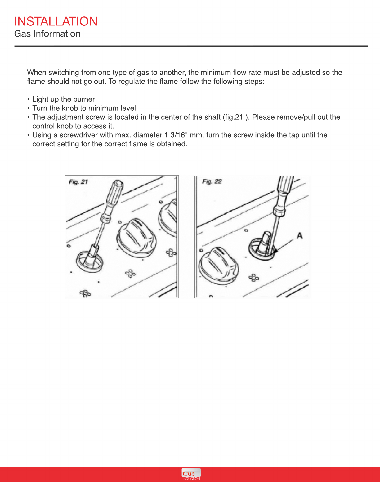
When switching from one type of gas to another, the minimum flow rate must be adjusted so the
flame should not go out. To regulate the flame follow the following steps:
• Light up the burner
• Turn the knob to minimum level
• The adjustment screw is located in the center of the shaft (fig.21 ). Please remove/pull out the
control knob to access it.
•
• Using a screwdriver with max. diameter 1 3/16" mm, turn the screw inside the tap until the
correct setting for the correct flame is obtained.
INSTALLATION
Gas Information
When all connections have been made, make sure all cooktop controls are in the off position and
turn on the main gas supply valve. Use a liquid leak detector at all joints and connections to check
for leaks in the system.
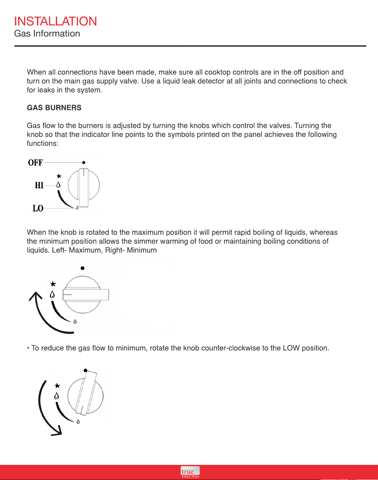
GAS BURNERS
Gas flow to the burners is adjusted by turning the knobs which control the valves. Turning the
knob so that the indicator line points to the symbols printed on the panel achieves the following
functions:
When the knob is rotated to the maximum position it will permit rapid boiling of liquids, whereas
When the knob is rotated to the maximum position it will permit rapid boiling of liquids, whereas
the minimum position allows the simmer warming of food or maintaining boiling conditions of
liquids. Left- Maximum, Right- Minimum
• To reduce the gas flow to minimum, rotate the knob counter-clockwise to the LOW position.
INSTALLATION
Gas Information
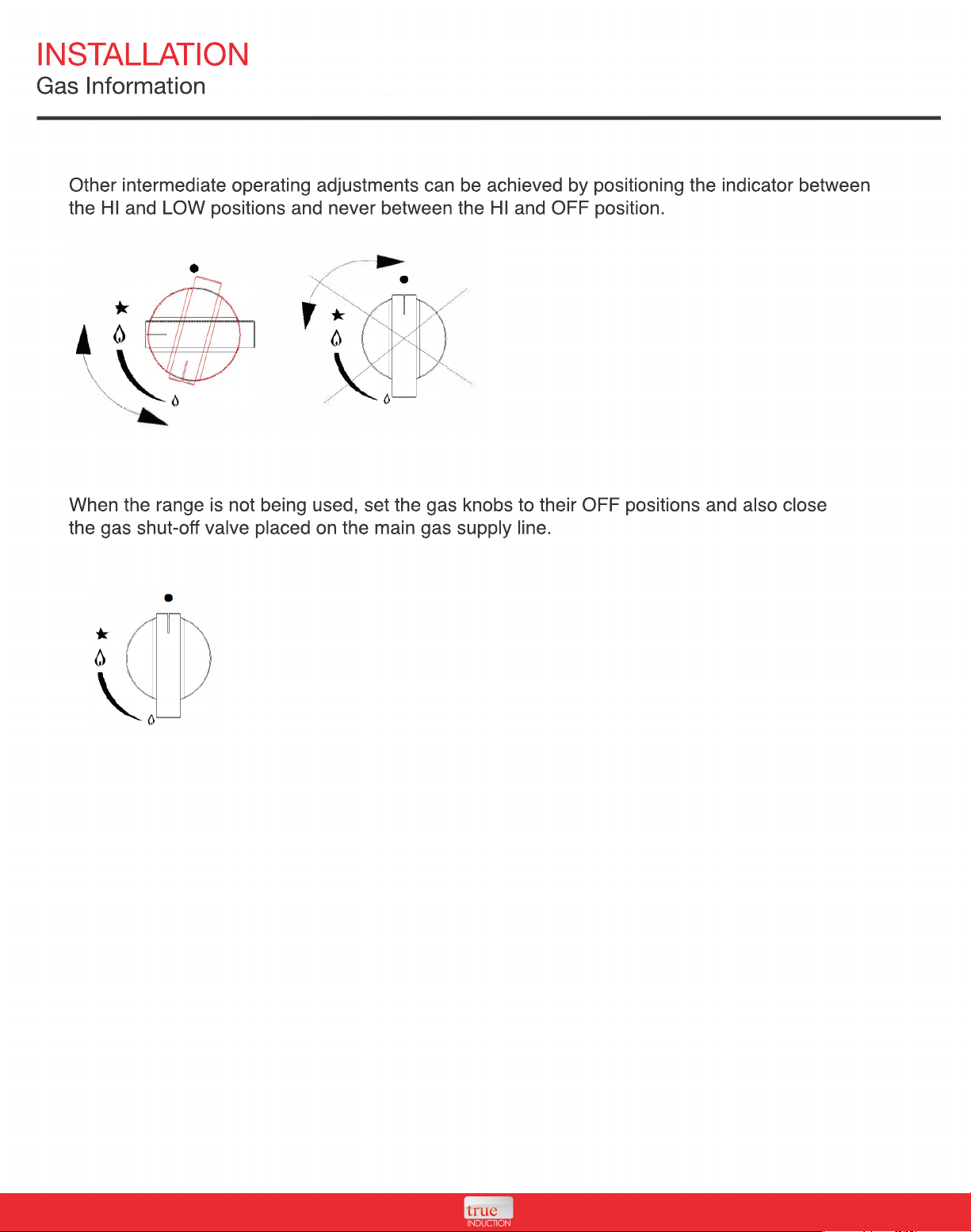
Other intermediate operating adjustments can be achieved by positioning the indicator between
the HI and LOW positions and never between the HI and OFF position.
When the range is not being used, set the gas knobs to their OFF positions and also close
the gas shut-off valve placed on the main gas supply line.
INSTALLATION
Gas Information
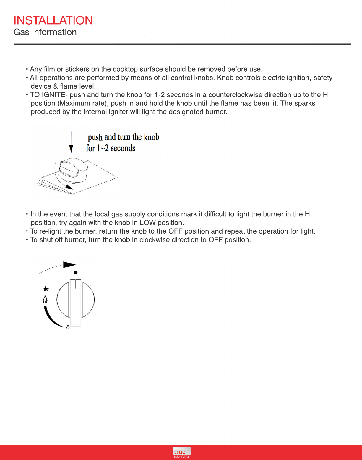
• Any film or stickers on the cooktop surface should be removed before use.
• All operations are performed by means of all control knobs. Knob controls electric ignition, safety
device & flame level.
• TO IGNITE- push and turn the knob for 1-2 seconds in a counterclockwise direction up to the HI
position (Maximum rate), push in and hold the knob until the flame has been lit. The sparks
produced by the internal igniter will light the designated burner.
• In the event that the local gas supply conditions mark it di
• In the event that the local gas supply conditions mark it difficult to light the burner in the HI
position, try again with the knob in LOW position.
• To re-light the burner, return the knob to the OFF position and repeat the operation for light.
• To shut off burner, turn the knob in clockwise direction to OFF position.
INSTALLATION
Gas Information
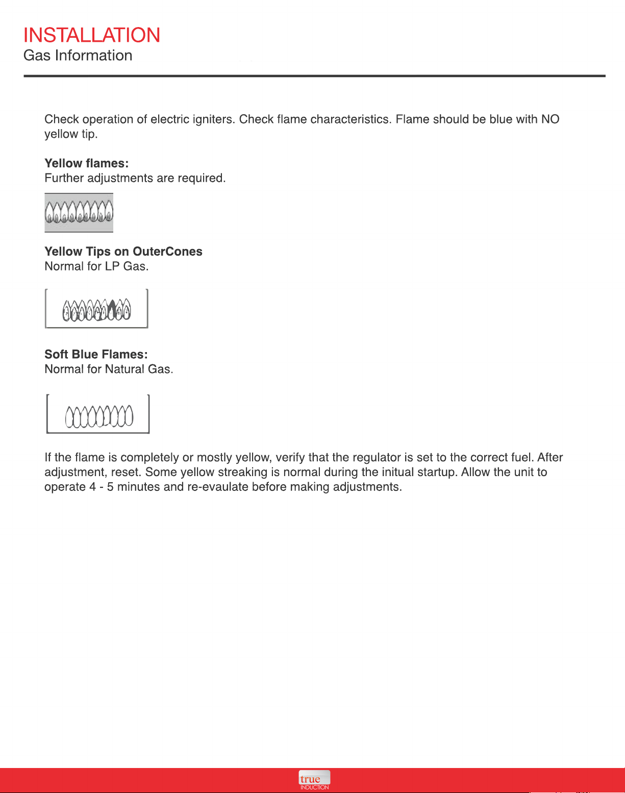
Check operation of electric igniters. Check flame characteristics. Flame should be blue with NO
yellow tip.
Yellow flames:
Further adjustments are required.
Yellow Tips on OuterCones
Normal for LP Gas.
Soft Blue Flames:
Normal for Natural Gas.
Normal for Natural Gas.
If the flame is completely or mostly yellow, verify that the regulator is set to the correct fuel. After
adjustment, reset. Some yellow streaking is normal during the initual startup. Allow the unit to
operate 4 - 5 minutes and re-evaulate before making adjustments.
INSTALLATION
Gas Information
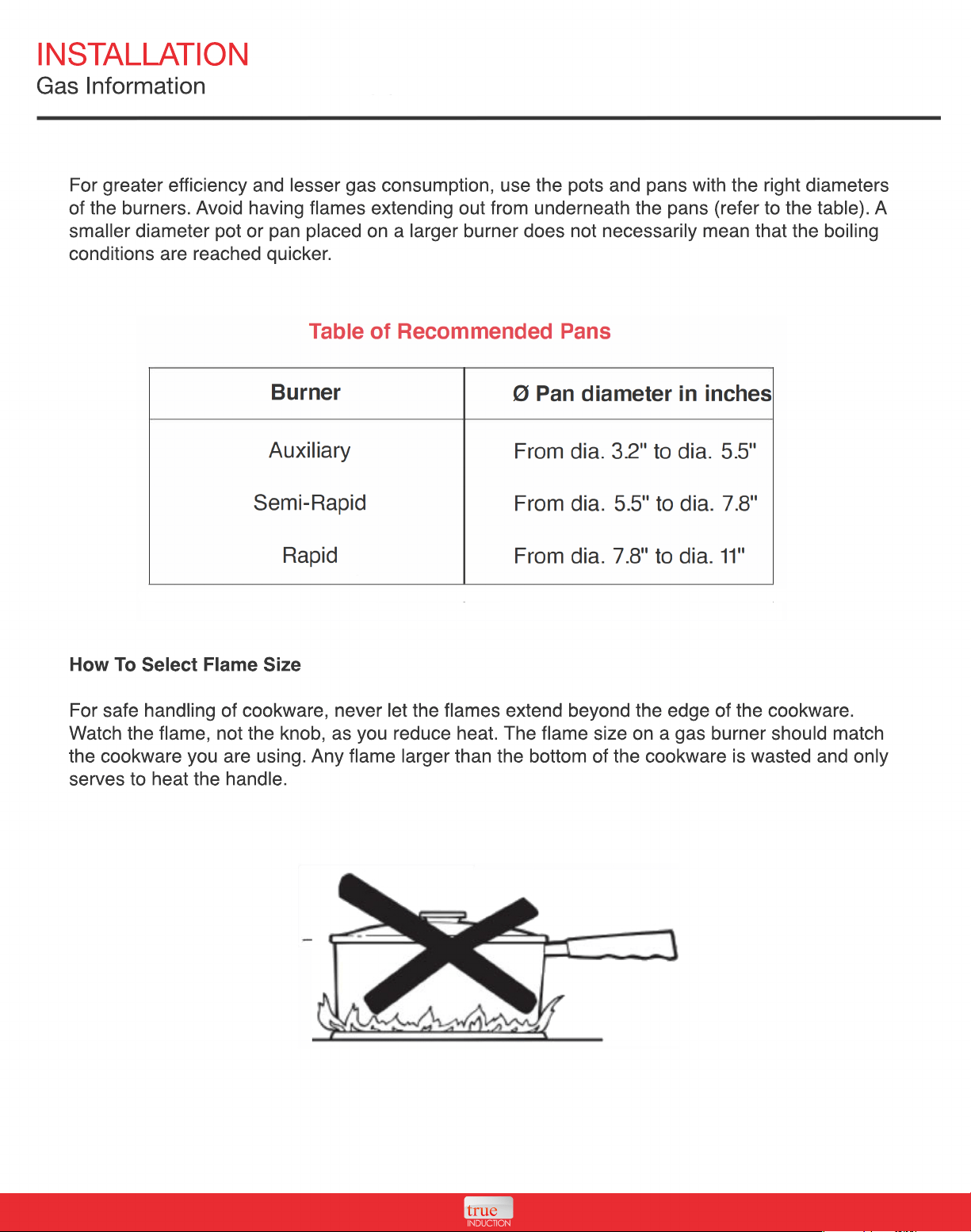
For greater efficiency and lesser gas consumption, use the pots and pans with the right diameters
of the burners. Avoid having flames extending out from underneath the pans (refer to the table). A
smaller diameter pot or pan placed on a larger burner does not necessarily mean that the boiling
conditions are reached quicker.
How To Select Flame Size
For safe handling of cookware, never let the flames extend beyond the edge of the cookware.
For safe handling of cookware, never let the flames extend beyond the edge of the cookware.
Watch the flame, not the knob, as you reduce heat. The flame size on a gas burner should match
the cookware you are using. Any flame larger than the bottom of the cookware is wasted and only
serves to heat the handle.
INSTALLATION
Gas Information
During a power failure the burners will not light automatically. In an emergency, a cooktop burner
may be lit with a match by following the steps below.
WARNING: Lighting gas burners with a match is dangerous. You should match light the cooktop
burners only in an emergency. On models equipped, check to be sure the cooktop is in the
UNLOCKED position.
1. Light a match and hold the flame near the burner you want to light. Wooden matches work
best.
2.
2. Push in and turn the control knob slowly. Be sure you are turning the correct knob for the
burner you are lighting.
NOTE: If the burner does not light within five seconds, turn the knob off, and wait one minute
before trying again.
The Burner Flames
T
Turn each burner on. Flames should be blue in color with no trace of yellow (yellow tips on outer
cones normal for LP gas). The burner flames should not flutter or blow away from the burner. The
flame should be no less than 1 /4" on the lowest setting and no greater than 1-1/2" on highest
setting.
WARNING: If you attempt to measure the flame, please use caution. Risk of burn may occur.
USING THE COOKTOP
Unit Functions
Using the Induction Cooktop portion of your unit
• Plug the power plug into a standard outlet.
• The Power button will light up and the unit will sound to indicate on.
• The device will remain in standby mode, awaiting user direction.
• Place ferromagnetic cookware (with water, oil, or food already inside) on the center of the
glass-ceramic top center.
•
• Now press the Power button on the control panel, this will turn the cooktop on. The power
display will blink and sound another indicator.
• Press the Heat function key once. The pre-set power level "5" is the default selection as the
device turns on.
• Using the +I - keys you can change the settings at any time, ranging from 1- 10. This is
considered to be the HEAT function.
Using the Temperature Setting
Using the +I - keys you can change the temperature settings at any time. Settings range from
Using the +I - keys you can change the temperature settings at any time. Settings range from
150-450 degrees Fahrenheit. (Exact temperatures: 150, 180, 210, 240, 270, 300, 330, 360, 390,
420 and 450 F).
USING THE COOKTOP
Unit Functions
Using the Timer Function
• After selecting HEAT or TEMP mode, press the TIMER button once. The display will show the
number "O". Using the+ and - buttons you can select the operating time in 1-minute intervals
(max 150 minutes).
•
• The display will count down the duration in minutes. Once the time is up, the unit sounds and
automatically goes into standby mode. To continue cooking, press the Power button and Heat
button to restart.
• During the timer operation, you can change the timer duration at any time with the arrow keys.
The device's built-in memory maintains the HEAT or TEMP settings previously entered.
• You can also change the HEAT or TEMP settings without affecting the current timer setting.
Built-In Safety Shut Off
•
• The True Induction cooktop is designed to automatically shut off after 150 minutes of use. This
built-in auto shut off is a safety feature.
• This function occurs for both the HEAT and TEMP settings. The panel displays "H" if the cooking
zone is hot.
• In the event your food requires further cooking, the unit can easily be turned back on and reset
to the desired setting.
Turning the Unit Off
•
• When you are finished cooking, simply press the Power button to turn off the machine.
• Upon completion of cooking, the fan may remain on until the unit has cooled.
USING THE COOKTOP
Compatible Cookware
Induction requires pots and pans that are made of ferrous (meaning magnetic) materials. Check
your cookware's retail box for the induction symbol.
To tell if your current cookware is compatible with the induction technology, check to see if a
magnet holds to your cookware. If your magnet stays, then your cookware is ready to be used on
the True Induction cooktop.
Optimal cookware has a flat bottom and a diameter of 4.5 - 10 inches. Round, flat bottom pans
Optimal cookware has a flat bottom and a diameter of 4.5 - 10 inches. Round, flat bottom pans
give the best results. Pans with warped or curved bottoms will not heat evenly. For wok cooking,
use a flat-bottom wok. Do not use a wok with a support ring.
The following are NOT COMPATIBLE
Heat-resistant glass, ceramid, copper, aluminum pans/pots, round bottomed cookware, or
cookware with a base less than 4.5 inches.
CLEANING AND MAINTENANCE
Unit Care
IMPORTANT: Before any operation of cleaning and maintenance, disconnect the appliance from
the electrical supply. It's required to clean when the appliance has cooled.
• Avoid leaving alkaline or acidic substances (lemon juice, vinegar, etc.) on the surfaces.
• Avoid using cleaning products with a chlorine or acidic base.
• Burner & grids can be removed and cleaned with appropriate detergent.
•
• After cleaning it is very important to check that the burner flame distributor and the cap are
correctly repositioned. Also, check the electrode & Thermocouple are clean to ensure
trouble-free sparking.
• Stainless steel can be stained if it's in contact with highly calcareous water or aggressive
detergents (containing phosphorus). It is recommended these parts be cleaned with water and
then dried well.
•
• Keep cooktop area clear and free from combustible materials, gasoline, and other flammable
vapors and liquids.
• Storage on the cooktop - Flammable materials should not be stored on or near surface units.
• Top burner flame size should be adjusted so it does not extend beyond the edge of the cooking
utensil.
TROUBLESHOOTING
Error Messages
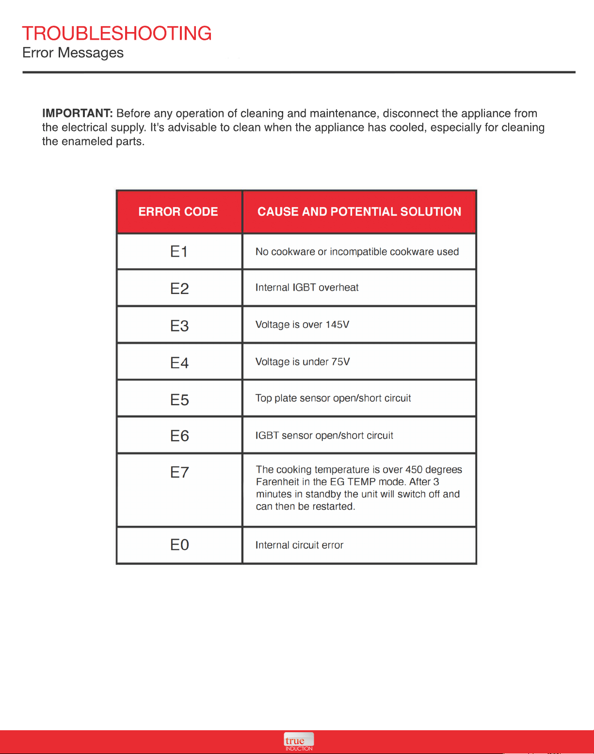
IMPORTANT: Before any operation of cleaning and maintenance, disconnect the appliance from
the electrical supply. It's advisable to clean when the appliance has cooled, especially for cleaning
the enameled parts.
TROUBLESHOOTING
FAQ - Induction Portion
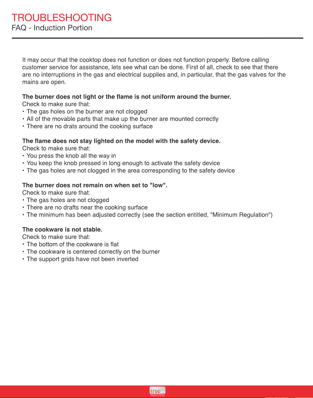
It may occur that the cooktop does not function or does not function properly. Before calling
customer service for assistance, lets see what can be done. First of all, check to see that there
are no interruptions in the gas and electrical supplies and, in particular, that the gas valves for the
mains are open.
The burner does not light or the flame is not uniform around the burner.
Check to make sure that:
• The gas holes on the burner are not clogged
•
• All of the movable parts that make up the burner are mounted correctly
• There are no drats around the cooking surface
The flame does not stay lighted on the model with the safety device.
Check to make sure that:
• You press the knob all the way in
• You keep the knob pressed in long enough to activate the safety device
• The gas holes are not clogged in the area corresponding to the safety device
The burner does not remain on when set to "low".
The burner does not remain on when set to "low".
Check to make sure that:
• The gas holes are not clogged
• There are no drafts near the cooking surface
• The minimum has been adjusted correctly (see the section entitled, "Minimum Regulation")
The cookware is not stable.
Check to make sure that:
•
• The bottom of the cookware is flat
• The cookware is centered correctly on the burner
• The support grids have not been inverted
TROUBLESHOOTING
FAQ - Gas Portion
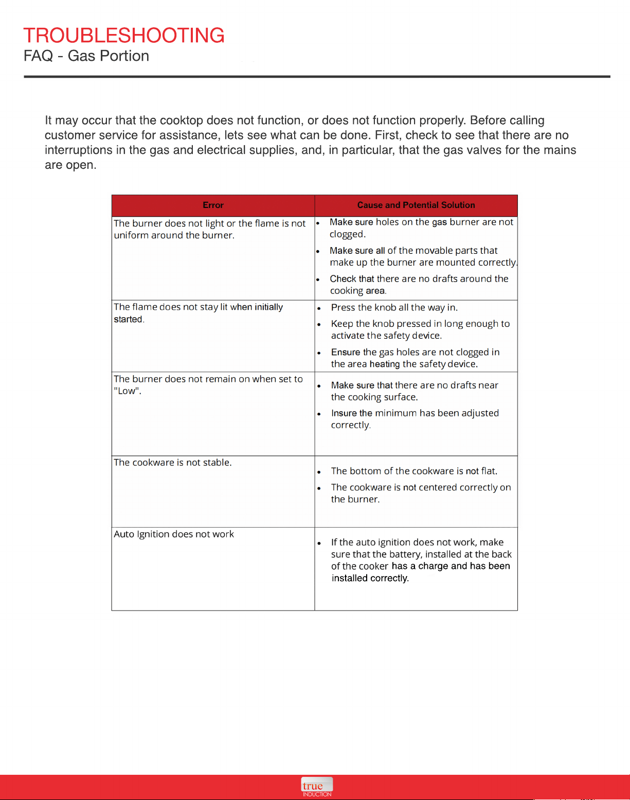
It may occur that the cooktop does not function, or does not function properly. Before calling
customer service for assistance, lets see what can be done. First, check to see that there are no
interruptions in the gas and electrical supplies, and, in particular, that the gas valves for the mains
are open.
has a charge and has been
installed correctly.
TROUBLESHOOTING
FAQ - Gas Portion
It may occur that the cooktop does not function, or does not function properly. Before calling
customer service for assistance, lets see what can be done. First, check to see that there are no
interruptions in the gas and electrical supplies, and, in particular, that the gas valves for the mains
are open.
SAFETY INFORMATION
When using electrical appliances, basic safety precautions should always be followed. For the
True Induction cooker, it is essential to heed all precautions:
• When the unit is on, do not touch outside the control panel as the surface may contain residual
heat.
• To protect against electric shock, do not immerse cord plugs or cooker in water (or other liquid
substances).
• When using any electric appliance used around children, close supervision is required.
•
• Do not operate any appliance with a damaged cord or plug, after a malfunction or if it has been
damaged in any manner. Read the seller's guidelines for warranty repairs and returns.
• Do not cook on a broken or damaged cooktop as spillovers may penetrate the surface and
create a risk of electric shock.
• To avoid potential injury, do not use accessory attachments which aren't recommended by the
manufacturer.
•
• Do not let the cord dangle over the edge of the table or counter. Keep the cord away from hot
surfaces.
• Do not place cooktop on or near: hot gas, electric burner or heated oven.
• To prevent accidents and achieve optimal fan ventilation, allow for sufficient space around the
cooking area.
• Items with a magnetic field such as: radios, televisions, credit cards, cassette tapes etc., can
affect the unit.
•
• The power cord provided has been sized accordingly, however, with caution and care extension
cords may be used.
The marked electrical rating should be at least as great as the electrical rating of the appliance.
The cord should be arranged so that it will not drape over the countertop or tabletop where it can
be pulled on by children or tripped over.
Do not use with empty pans/pots.
•
• Do not place metallic objects such a knives, forks, spoons, lids, cans or aluminum foil on the
cooktop.
• To prevent accidents and achieve optimal ventilation, allow for sufficient space around the
cooking area.
SAFETY INFORMATION
• This appliance has a polarize plug (one blade is wider than the other). To reduce the risk of
electric shock, the plug will fit on the outlet only one way. If the prongs do not fit fully, reverse the
plug. If it still does not fit, contact the seller for warranty support; do not attempt to modify the
plug in any way.
• To properly turn off unit press the Power button.
• It is important to be aware that the unit's surface will remain hot for a short period of time after
use.
•
• Disconnect power and allow to cool before performing any maintenance or repairs.
• Clean cooktop with caution - do not clean while unit is still hot, some cleaners produce steam or
fumes if applied to a heated surface.
• Do not use cooktop for any other use then directed by the manufacturer.
