Loading ...
Loading ...
Loading ...
this heater has been certified to be used with
polypropylene vent systems. A polypropylene to
PVC end connection is required. Optional wall
plates that fit the polypropylene venting are also
available.
Carefully inspect the entire venting system for any
signs of cracks or fractures, particularly at joints
between elbows and other fittings and straight runs
of vent pipe. Check system for signs of sagging or
other stresses in joints as a result of misalignment
of any components in the system. If any of these
conditions are found, they must be corrected in
accordance with the venting instructions in this
manual before completing installation and putting
the water heater into service.
The vent piping shall be connected to the blower
with the rubber coupling and secured with gear
clamps. The coupling and clamps are provided with
the heater.
Even though the flue gas temperature leaving the
blower is hot, some installations will have water
condense in the vent piping. If this occurs, then
adequate means of draining and disposing of the
condensate shall be made by the installer.
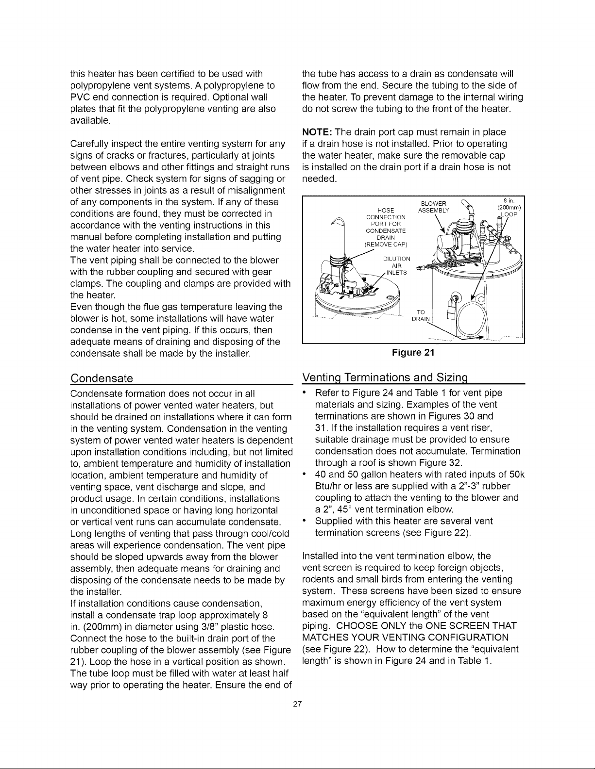
the tube has access to a drain as condensate will
flow from the end. Secure the tubing to the side of
the heater. To prevent damage to the internal wiring
do not screw the tubing to the front of the heater.
NOTE: The drain port cap must remain in place
if a drain hose is not installed. Prior to operating
the water heater, make sure the removable cap
is installed on the drain port if a drain hose is not
needed.
BLOWER (_
HOSE _E_Y
.... CONNECTION
_ ' PORT FOR
CONDENSATE
DRAIN
(REMOVE CAP)
/__ _ DILUTION
I _ AIR
__TS TO
DRAIN
Figure 21
8 in.
(200mm)
Condensate
Condensate formation does not occur in all
installations of power vented water heaters, but
should be drained on installations where it can form
in the venting system. Condensation in the venting
system of power vented water heaters is dependent
upon installation conditions including, but not limited
to, ambient temperature and humidity of installation
location, ambient temperature and humidity of
venting space, vent discharge and slope, and
product usage. In certain conditions, installations
in unconditioned space or having long horizontal
or vertical vent runs can accumulate condensate.
Long lengths of venting that pass through cool/cold
areas will experience condensation. The vent pipe
should be sloped upwards away from the blower
assembly, then adequate means for draining and
disposing of the condensate needs to be made by
the installer.
If installation conditions cause condensation,
install a condensate trap loop approximately 8
in. (200mm) in diameter using 3/8" plastic hose.
Connect the hose to the built-in drain port of the
rubber coupling of the blower assembly (see Figure
21). Loop the hose in a vertical position as shown.
The tube loop must be filled with water at least half
way prior to operating the heater. Ensure the end of
Venting Terminations and Sizing
• Refer to Figure 24 and Table 1 for vent pipe
materials and sizing. Examples of the vent
terminations are shown in Figures 30 and
31. If the installation requires a vent riser,
suitable drainage must be provided to ensure
condensation does not accumulate. Termination
through a roof is shown Figure 32.
• 40 and 50 gallon heaters with rated inputs of 50k
Btu/hr or less are supplied with a 2"-3" rubber
coupling to attach the venting to the blower and
a 2", 45 ° vent termination elbow.
• Supplied with this heater are several vent
termination screens (see Figure 22).
Installed into the vent termination elbow, the
vent screen is required to keep foreign objects,
rodents and small birds from entering the venting
system. These screens have been sized to ensure
maximum energy efficiency of the vent system
based on the "equivalent length" of the vent
piping. CHOOSE ONLY the ONE SCREEN THAT
MATCHES YOUR VENTING CONFIGURATION
(see Figure 22). How to determine the "equivalent
length" is shown in Figure 24 and in Table 1.
27
Loading ...
Loading ...
Loading ...