Loading ...
Loading ...
Loading ...
6
English
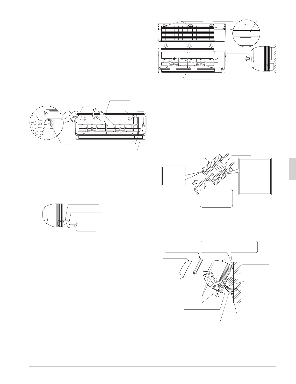
(4) Remove the front panel and the control box cover.
(Refer to Fig. 5)
< How to remove the front panel and control box
cover >
(1) Open the front panel by lifting from the bottom to the
point where it stops.
(2) Push the panel spacers on either side of the front
panel towards the center of the main unit and
remove.
(You can also remove it by sliding the front panel
either to the left or right and pulling it forward.)
(3) Remove the screw from the control box cover and
pull the tab forward.
Panel
spacer
Panel
spacer
Panel
spacer
Fig. 5
Ta b
Screw
Control box cover
Front panel
(1)
(2) (2)
(3)
(5) Point the pipe in the direction it will be routed out of
the unit.
For bottom-right and back-right piping
(Refer to Fig. 6)
• Wrap the drain hose and the refrigerant piping
together with the insulating tape (4) so that the drain
hose is below the refrigerant piping.
Insulating tape (4)
Drain hose
Fig. 6
Refrigerant piping
For left, bottom-left, and back-left piping
• Remove the front grille. (Refer to Fig. 7)
< How to remove the front grille >
Remove the front grille as described below when secur-
ing the indoor unit with screws or when attaching
Optional Accessories (wireless remote controller,
adapter PC board, etc.).
(1) Remove the front panel.
(2) Remove the screws (3 places) securing the front
grille.
(3) Remove the tabs (3 places) securing the front grille
by pushing them in the direction of the arrows.
(4) Making sure not to catch the horizontal aps, remove
the front grille by pulling in the direction of the arrow.
Tab position Tab position
Front grille
Fig. 7
Ta b
(2)
(2) (2)
(3) (3)
(4)
(3)
Screw position
Screw position
• Remove the drain plug, the insulating tube, and the drain
hose from the drain pan and replace.
(Refer to Fig. 8)
• Connect the eld refrigerant piping ahead of time, match-
ing it to the liquid pipe and gas pipe marks engraved on
the installation panel (accessory) (1).
< Replacing the drain hose and drain plug >
(1) Remove the drain plug and insulating tube.
(2) Remove the drain hose and replace onto the left side.
(3) Replace the drain plug and the insulating tube onto the
right side.
Drain plug
Insulating tube
Fig. 8
Do not place
lubricant
(refrigerant oil)
when inserting.
This may cause
deterioration and
water leaks.
Insert using a
hexagon wrench
(5/32 in. (4 mm)).
Make sure
there are
no gaps.
(6) Hook the indoor unit onto the installation panel.
(Refer to Fig. 9)
• Placing buffering material between the wall and the
indoor unit at this time will make work easier.
Refrigerant piping
Be sure to pass all
wires through
the wiring guide.
Ta b
(There are 2 places.)
Wiring (locally procured)
Transmission wiring,
Remote controller wiring
Wall
Front panel Front grille
Control box cover
Place buffering
material
Power supply
wiring,
Ground wiring
Conduit
Hook the indoor unit hook onto
the installation panel (1).
Fig. 9
Installation panel
(accessory) (1)
For bottom-right and back-right piping
• Pass the drain hose and the refrigerant piping to the
wall.
01_EN_3PN07521-5H.indd 6 7/9/2018 14:13:34
Loading ...
Loading ...
Loading ...