
Loading ...
Loading ...
Loading ...
4
WARNING – TO REDUCE THE RISK OF FIRE, ELECTRIC SHOCK, OR
INJURY TOPERSONS, OBSERVE THE FOLLOWING:
a) Use this unit only in the manner intended by the manufacturer. If you have
questions, contact the manufacturer.
b) Before servicing or cleaning unit, switch power off at service panel and lock
the servicedisconnecting means to prevent power from being switched on
accidentally. When the servicedisconnecting means cannot be locked, securely
fasten a prominent warning device, such as atag, to the service panel.
c) Installation work and electrical wiring must be done by qualified person(s) in
accordance withall applicable codes and standards, including fire-rated
construction.
d) Sufficient air is needed for proper combustion and exhausting of gases
through the flue(chimney) of fuel burning equipment to prevent back drafting.
Follow the heating equipmentmanufacturer’s guideline and safety standards
such as those published by the National FireProtection Association (NFPA), and
the American Society for Heating, Refrigeration and AirConditioning Engineers
(ASHRAE), and the local code authorities.
e) When cutting or drilling into wall or ceiling, do not damage electrical wiring
and other hiddenutilities.
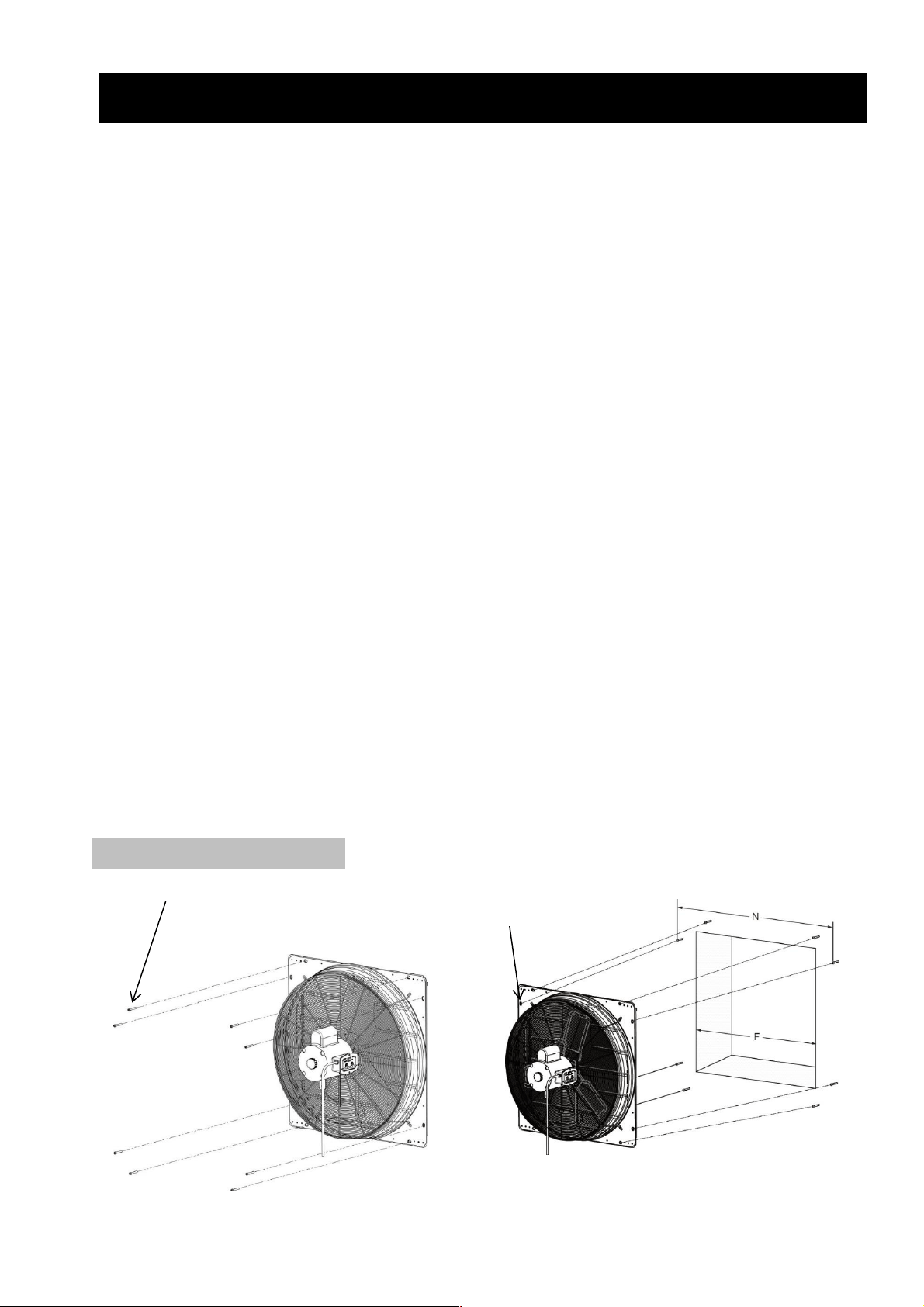
1. The unit should be only securely mounted on the wooden plank.
NOTE: Allowing the fan frame to flex or move will result in excess vibrations,
which may cause possible premature motor, propeller, or shutter failure.
2. Install the shutter fan through 8 holes with screws. (Screws are not
included.)
INSTALLATIONINSTRUCTIONS
Screws
Install on wooden plank.
8 holes
Loading ...
Loading ...
Loading ...