HEAT STRIP INSTALLATION KIT
KIT D’INSTALLATION DE BANDE CHAUFFANTE
KIT DE INSTALACIÓN DE TIRAS DE CALE-
FACCIÓN
MODEL/MODÈLE/MODELO: C-FACR15SA-A04, C-FACR15HESA-A01
LIPPERT NO/LIPPERT NO./LIPPERT N.°: 2021123626, 2021132287
INSTALLATION GUIDE ....................................................EN
GUIDE D’INSTALLATION ................................................................... FR
GUÍA DE INSTALACIÓN ..................................................ES
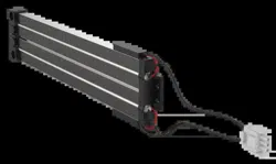
* Product picture for reference only.
* Photo du produit pour référence uniquement.
* El producto de la imagen es solo de referencia.
This manual will guide you through proper installation of the Furrion heat strip. If
retrofitting, please refer to your existing user manual to uninstall the rooftop and trim
kit from the RV, and then follow the instructions to install the heat strip.
DANGER
Electric Shock Hazard
● Disconnect power or shut off the air conditioner circuit breaker
before installation.
● Failure to do so can result in electric shock.
WHAT’S IN THE BOX
● Heat Strip
● ST4 x 9mm Screw with Washer
● Electric Control Box
● User Manual
● Warranty Manual
INSTALL/REPLACING THE HEAT STRIP
IMPORTANT: Installation of the heat strip must be carried out by a professional/
certificated technician only.
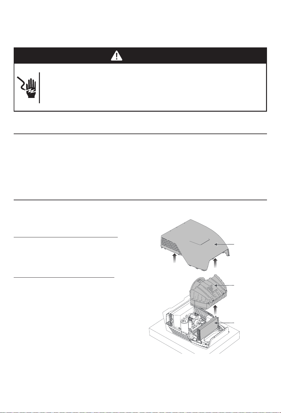
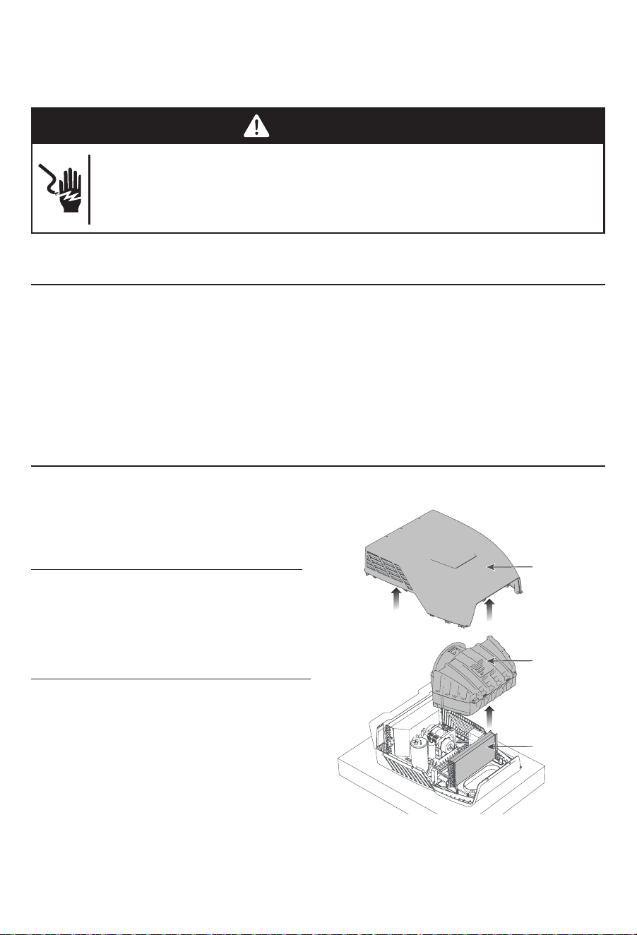
Disassemble the Top Unit
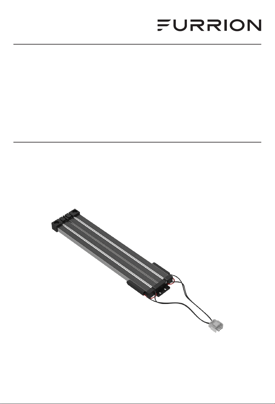
Remove the rooftop cover by removing
the fixing screws. Pull to remove the
evaporator EPP cover to access the
evaporator. (Fig. 1)
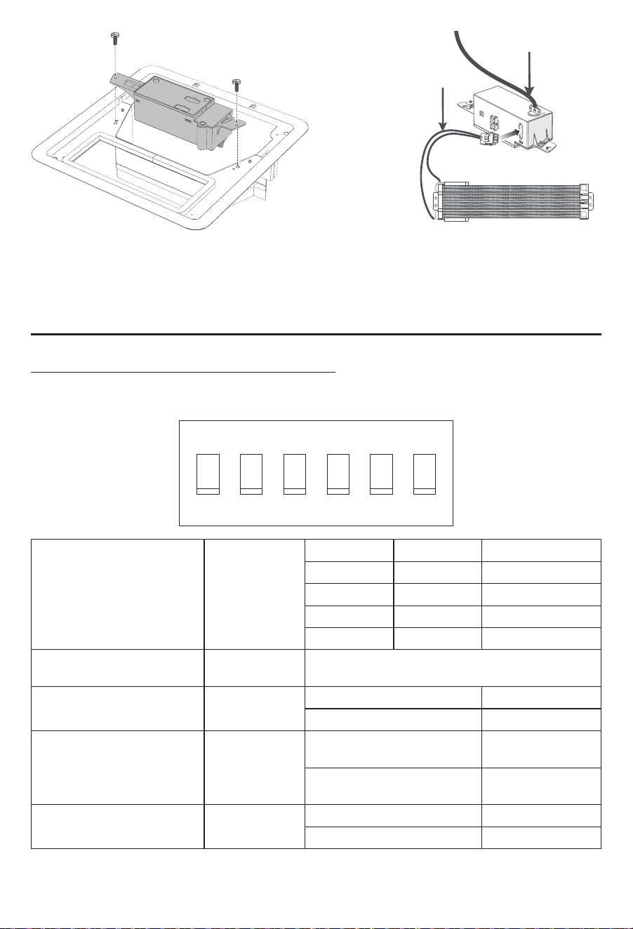
Heat Strip Installation
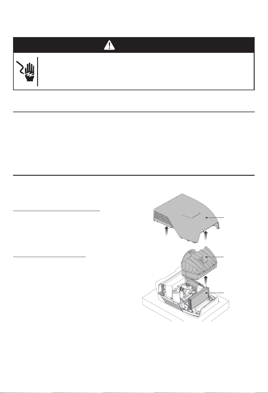
Use 4 ST4*9mm screws and washers
(provided) to attach the heat strip on the
evaporator. (Fig. 2)
Fix the harnesses together with nylon
cable ties (not provided). Then pass the
2 harnesses down through the air intake
vent to the RV. (Fig. 3)
NOTE: Retain wire harnesses away from
the electric heater element and evaporator
to prevent being damaged.
Install the EPP top cover of the evaporator and the top cover back. Ensure the pipe
outlet is sealed well with the existing silicon sealant.
Evaporator
EPP Cover
Rooftop Cover
Fig. 1
Evaporator
Heat Strip
Heat strip wire
Rooftop unit wire
Fig. 2 Fig. 3
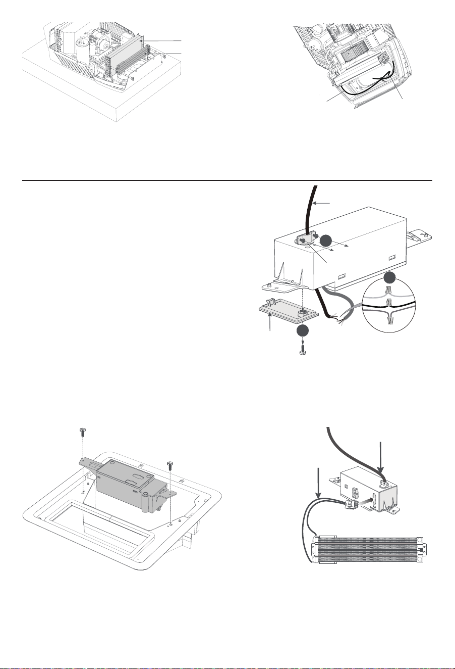
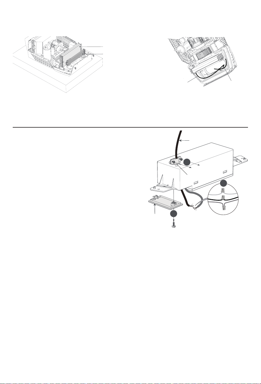
WIRE CONNECTION
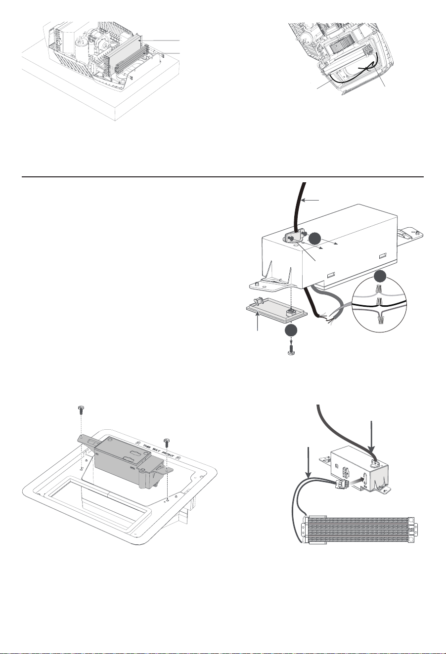
1. Remove the controller cover on the
control box by unscrewing its screw.
2. Loosen the 2 screws of the power cord
clamp on the back of the control box.
3. Pass the 115VAC power cord through
the cable clamp hole and make wire
connections following the below color
codes (Fig. 4):
– Black - Hot
– White - Neutral
– Green/Yellow - Ground
4. Plug the 3-pin connector of the rooftop
into the 3-pin terminal interface on the
control box. (Fig. 5)
5. When the heat strip is connected properly, secure the electrical box trim kit body.
(Fig. 6)
115VAC Power Cord
Heat Strip Cable
Fig. 5 Fig. 6
The installation is completed.
Controller Cover
Cable Clamp
3
1
115VAC Power Cord
2
Fig. 4
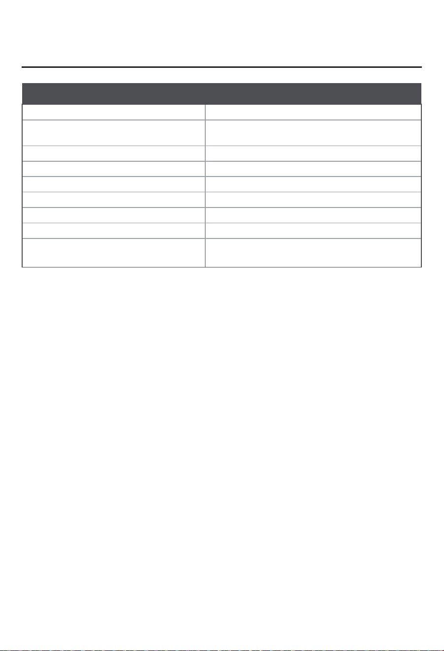
SET UP
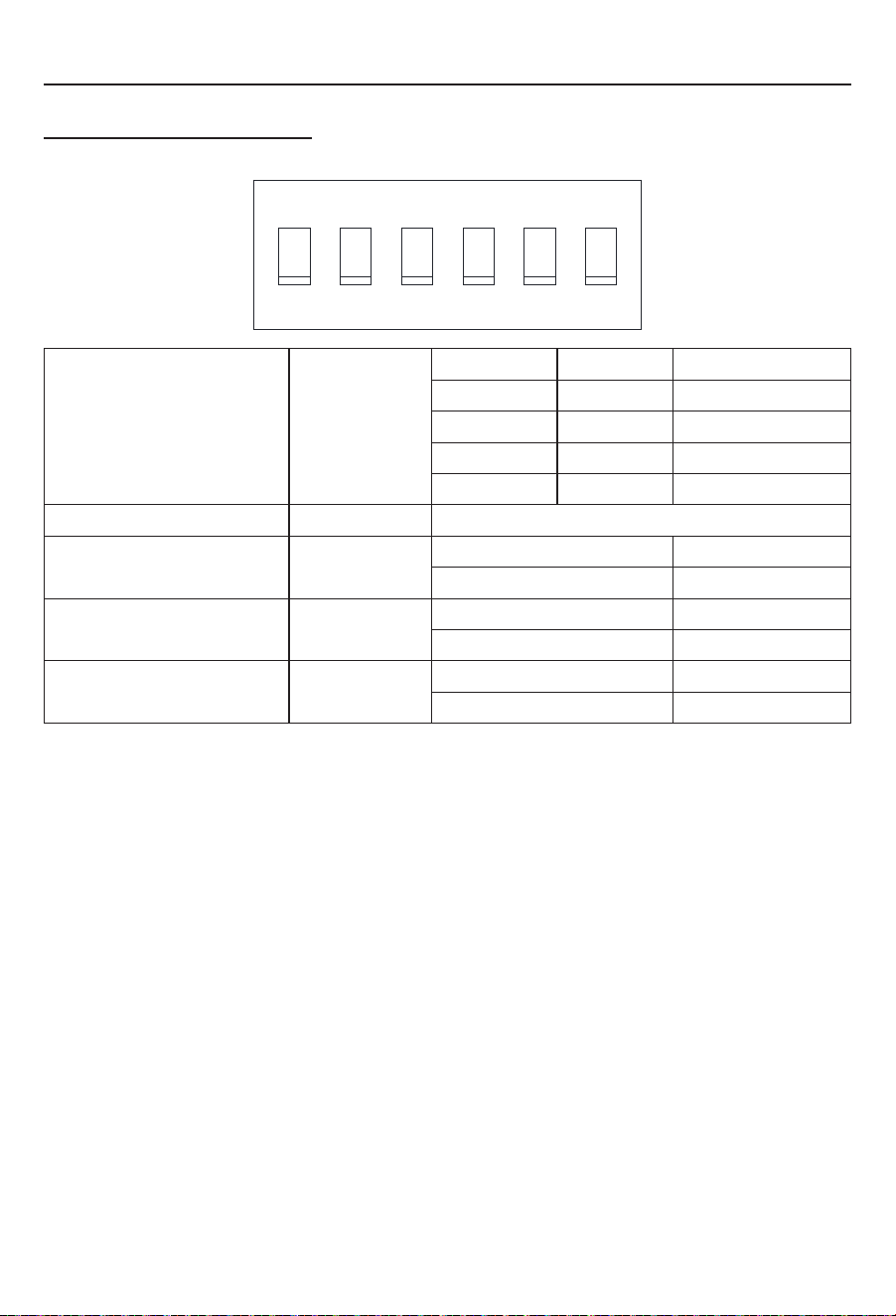
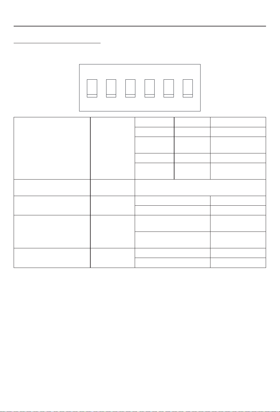
Set up the DIP Switches
Set up the control box dip switches as indicated in the illustration and table below.
ON
1
2
3
4
5
6
Zone Selection DIP 1 : DIP 2 DIP 1 DIP 2 Selected
OFF OFF ZONE1
OFF ON ZONE2
ON OFF ZONE3
ON ON ZONE4
Heat Pump (selected models) DIP 3 Reserved
Furnace DIP 4 OFF Furnace Off
ON Furnace On
Electric Heat (selected
models)
DIP 5 OFF Heat Strip Off
ON Heat Strip On
Analog / Digital DIP 6 OFF Digital
ON Analog
Switch DIP 5 to ON position to activate the heat strip function.
Refer to your Wall Thermostat for operation of your heat strip.
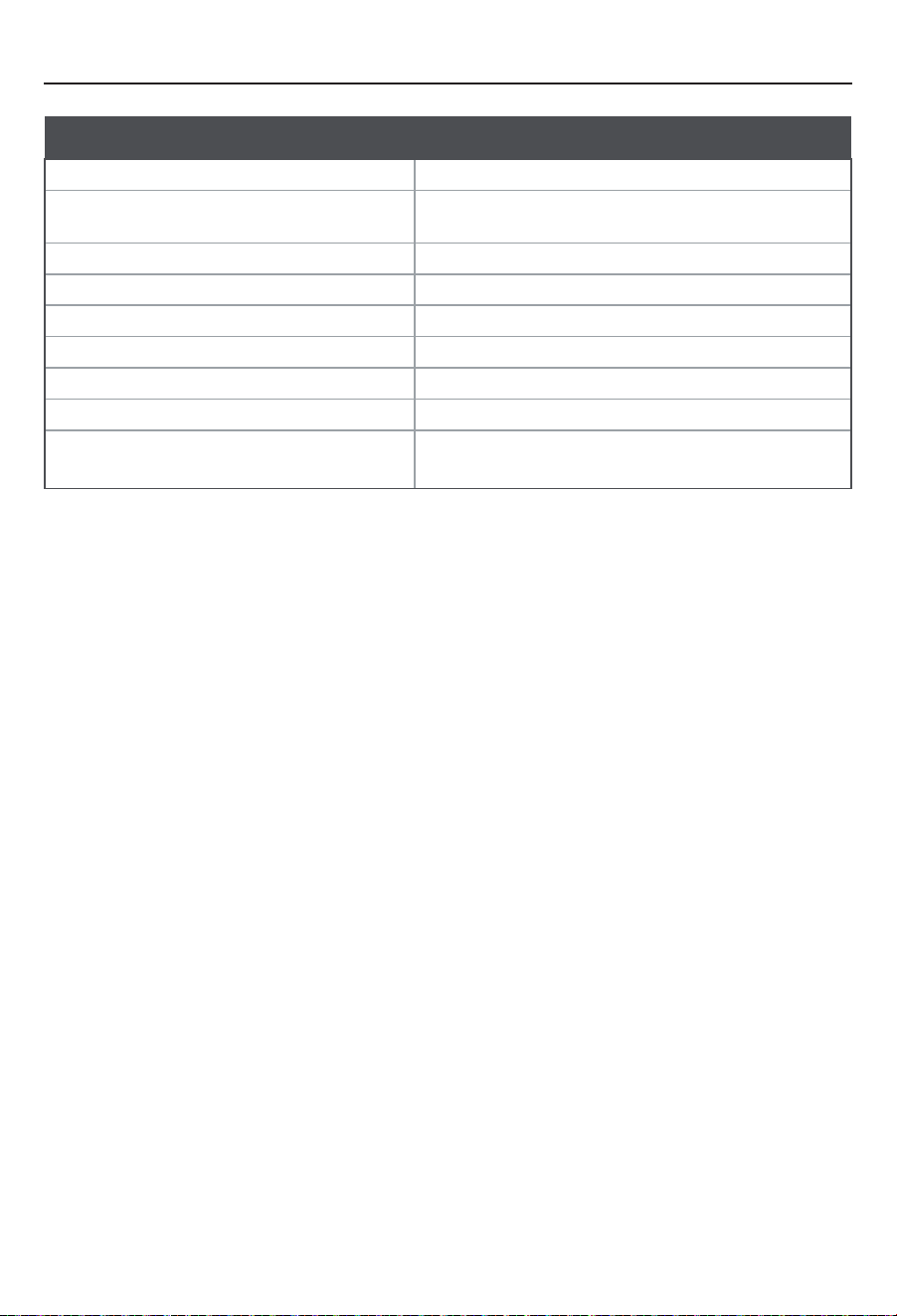
SPECIFICATION
Specifications
Heating Capacity 1,500W
Applicable Ambient Temperature in cooling -7°C~30°C (19°F~86°F)
Volts/Hertz 115V~/60Hz/1Ph
Power Watts 1,500W
Amps 14.6A
Power Cord Gauge AWG14 (1.6 mm2)
Dimensions (W x H x D) 1713/16" x 15/16" x 3⅞" (452mm x 23.5mm x 98mm)
Weight (lbs/kg) 1.63/0.74
Safety Standard
CSA/UL 60335-1, Second Edition &
CSA/UL 60335-2-40, Second Edition
HEAT STRIP INSTALLATION KIT
KIT D’INSTALLATION DE BANDE CHAUFFANTE
KIT DE INSTALACIÓN DE TIRAS DE CALE-
FACCIÓN
MODEL/MODÈLE/MODELO: C-FACR15SA-A04, C-FACR15HESA-A01
LIPPERT NO/LIPPERT NO./LIPPERT N.°: 2021123626, 2021132287
INSTALLATION GUIDE ....................................................EN
GUIDE D’INSTALLATION ................................................................... FR
GUÍA DE INSTALACIÓN ..................................................ES
* Product picture for reference only.
* Photo du produit pour référence uniquement.
* El producto de la imagen es solo de referencia.
This manual will guide you through proper installation of the Furrion heat strip. If
retrofitting, please refer to your existing user manual to uninstall the rooftop and trim
kit from the RV, and then follow the instructions to install the heat strip.
DANGER
Electric Shock Hazard
● Disconnect power or shut off the air conditioner circuit breaker
before installation.
● Failure to do so can result in electric shock.
WHAT’S IN THE BOX
● Heat Strip
● ST4 x 9mm Screw with Washer
● Electric Control Box
● User Manual
● Warranty Manual
INSTALL/REPLACING THE HEAT STRIP
IMPORTANT: Installation of the heat strip must be carried out by a professional/
certificated technician only.
Disassemble the Top Unit
Remove the rooftop cover by removing
the fixing screws. Pull to remove the
evaporator EPP cover to access the
evaporator. (Fig. 1)
Heat Strip Installation
Use 4 ST4*9mm screws and washers
(provided) to attach the heat strip on the
evaporator. (Fig. 2)
Fix the harnesses together with nylon
cable ties (not provided). Then pass the
2 harnesses down through the air intake
vent to the RV. (Fig. 3)
NOTE: Retain wire harnesses away from
the electric heater element and evaporator
to prevent being damaged.
Install the EPP top cover of the evaporator and the top cover back. Ensure the pipe
outlet is sealed well with the existing silicon sealant.
Evaporator
EPP Cover
Rooftop Cover
Fig. 1
Evaporator
Heat Strip
Heat strip wire
Rooftop unit wire
Fig. 2 Fig. 3
WIRE CONNECTION
1. Remove the controller cover on the
control box by unscrewing its screw.
2. Loosen the 2 screws of the power cord
clamp on the back of the control box.
3. Pass the 115VAC power cord through
the cable clamp hole and make wire
connections following the below color
codes (Fig. 4):
– Black - Hot
– White - Neutral
– Green/Yellow - Ground
4. Plug the 3-pin connector of the rooftop
into the 3-pin terminal interface on the
control box. (Fig. 5)
5. When the heat strip is connected properly, secure the electrical box trim kit body.
(Fig. 6)
115VAC Power Cord
Heat Strip Cable
Fig. 5 Fig. 6
The installation is completed.
Controller Cover
Cable Clamp
3
1
115VAC Power Cord
2
Fig. 4
SET UP
Set up the DIP Switches
Set up the control box dip switches as indicated in the illustration and table below.
ON
1
2
3
4
5
6
Zone Selection DIP 1 : DIP 2 DIP 1 DIP 2 Selected
OFF OFF ZONE1
OFF ON ZONE2
ON OFF ZONE3
ON ON ZONE4
Heat Pump (selected models) DIP 3 Reserved
Furnace DIP 4 OFF Furnace Off
ON Furnace On
Electric Heat (selected
models)
DIP 5 OFF Heat Strip Off
ON Heat Strip On
Analog / Digital DIP 6 OFF Digital
ON Analog
Switch DIP 5 to ON position to activate the heat strip function.
Refer to your Wall Thermostat for operation of your heat strip.
SPECIFICATION
Specifications
Heating Capacity 1,500W
Applicable Ambient Temperature in cooling -7°C~30°C (19°F~86°F)
Volts/Hertz 115V~/60Hz/1Ph
Power Watts 1,500W
Amps 14.6A
Power Cord Gauge AWG14 (1.6 mm2)
Dimensions (W x H x D) 1713/16" x 15/16" x 3⅞" (452mm x 23.5mm x 98mm)
Weight (lbs/kg) 1.63/0.74
Safety Standard
CSA/UL 60335-1, Second Edition &
CSA/UL 60335-2-40, Second Edition
Ce manuel vous guidera dans l’installation correcte de la bande chauante Furrion. En cas
d’installation ultérieure, veuillez vous reporter à votre manuel d’utilisation existant pour désinstaller
le kit de toit et de garniture du véhicule récréatif, puis suivez les instructions pour installer la bande
chauante.
DANGER
Risque de décharge électrique
● Débranchez le courant ou coupez le disjoncteur du climatiseur avant
l’installation.
● Le non-respect de cette consigne peut entraîner une décharge électrique
ou des brûlures.
CE QU’IL Y A DANS LA BOÎTE
● Bande chauante
● VisST4 x 9mm avec rondelle
● Boîte de commande électrique
● Manuel de l’utilisateur
● Manuel de garantie
INSTALLER/REMPLACER LA BANDE CHAUFFANTE
IMPORTANT: L’installation de la bande chauante doit être eectuée uniquement par un
technicien professionnel/certifié.
Démontage de l’unité supérieure
Retirez le couvercle du toit en enlevant les vis de
fixation. Tirez pour retirer le couvercle EPP de
l’évaporateur pour accéder à l’évaporateur. (Fig.1)
Installation de bande chauante
Utilisez 4 vis ST4*9mm et des rondelles
(fournies) pour fixer la bande chauante sur
l’évaporateur. (Fig.2)
Fixez les harnais ensemble à l’aide de colliers
de serrage en nylon (non fournis). Faites ensuite
passer les 2harnais par la prise d’air jusqu’aux
autos-caravanes. (Fig.3)
REMARQUE: Conservez les faisceaux de câbles
à l’écart de l’élément de chauage électrique et de
l’évaporateur pour éviter de les endommager.
Installez le couvercle supérieur EPP de
l’évaporateur et le couvercle supérieur en arrière. Assurez-vous que la sortie du tuyau est bien
scellée avec le mastic silicone existant.
Évaporateur
Couverture EPP
Couverture de toit
Fig.1
Évaporateur
Bande chauante
Fil de la bande chauante
Fil de l'unité de toit
Fig.2 Fig.3
CONNECTEUR DE FIL
1. Retirez le couvercle du contrôleur sur le
boîtier de commande en dévissant sa vis.
2. Desserrez les 2vis du collier de serrage du
cordon d’alimentation à l’arrière du boîtier de
commande.
3. Faites passer le cordon
d’alimentation115VAC par le trou du serre-
câble et eectuez les connexions des fils
en suivant les codes de couleur ci-dessous
(Fig.4):
- Noir - Chaud
- Blanc - Neutre
- Vert/Jaune - Mise à la terre
4. Branchez le connecteur à 3broches du haut
de toit sur l’interface de la borne à 3broches du boîtier de commande. (Fig.5)
5. Lorsque la bande chauante est correctement connectée, fixez le corps du kit de garniture
du boîtier électrique. (Fig.6)
Cordon d'alimentation 115 VCA
Câble de la bande chauante
N
eue
H
a
as
Gro
tesk D
i
sp
la
y
P
r
o
Fig.5 Fig.6
L’installation est terminée.
Couvercle du contrôleur
Serre-câble
3
1
Cordon d'alimentation 115 VCA
2
Fig.4
CONFIGURATION
Régler les interrupteurs DIP
Configurez les commutateurs DIP du boîtier de commande comme indiqué dans l’illustration et
le tableau ci-dessous.
MARCHE
1
2
3
4
5
6
Sélection des zones DIP1 DIP2 DIP1 DIP2 Sélectionné
ARRÊT (OFF) ARRÊT (OFF) ZONE1
ARRÊT (OFF) MARCHE
(ON)
ZONE2
MARCHE (ON) ARRÊT (OFF) ZONE3
MARCHE (ON) MARCHE
(ON)
ZONE4
Pompe à chaleur (modèles
sélectionnés)
DIP3 Réservé
Fourneau DIP4 ARRÊT (OFF) Fourneau éteint
MARCHE (ON) Fourneau en marche
Chauage électrique (certains
modèles)
DIP5 ARRÊT (OFF) ARRÊT (OFF) de la
bande chauante
MARCHE (ON) MARCHE (ON) de la
bande chauante
Analogique/numérique DIP6 ARRÊT (OFF) Digital
MARCHE (ON) Analogique
Mettez le DIP5 sur la position ON pour activer la fonction de bande chauante.
Reportez-vous à votre thermostat mural pour le fonctionnement de votre bande chauante.
SPÉCIFICATIONS
Spécifications
Capacité de chauage 1500W
Température ambiante applicable en
refroidissement
-7°C~30°C (19°F~86°F)
Volts/Hertz 115V~/60Hz/1Ph
Puissance en watts 1500W
Ampères 14.6 A
Jauge du cordon d’alimentation AWG14 (1,6mm2)
Dimension (L x H x P) 1713/16po x 15/16po x 3⅞po (452mm x 23,5mm x 98mm)
Poids (lb/kg) 1,63/0,74
Norme de sécurité
CSA/UL60335-1, deuxième édition&
CSA/UL60335-2-40, deuxième édition
Este manual lo guiará en la instalación correcta de la tira de calefacción Furrion.
Si se trata de un acondicionamiento, consulte el manual del usuario existente para
desinstalar el techo y el kit de ajuste del vehículo recreativo y siga las instrucciones
para instalar la tira de calefacción.
PELIGRO
Peligro de descarga eléctrica
● Desconecte la alimentación o apague el disyuntor del aire
acondicionado antes de la instalación.
● Si no lo hace, podría provocar una descarga eléctrica.
QUÉ HAY EN LA CAJA
● Tira de calefacción
● Tornillo ST4x9mm con arandela
● Caja de control eléctrico
● Manual de usuario
● Manual de garantía
INSTALACIÓN O REEMPLAZO DE LA TIRA DE
CALEFACCIÓN
IMPORTANTE: La instalación de la tira de calefacción debe ser realizada
únicamente por un técnico profesional/
certificado.
Desmontaje de la unidad superior
Retire la cubierta del techo quitando los
tornillos de fijación. Tire para retirar la
cubierta de EPP del evaporador para
acceder al evaporador. (Fig. 1)
Instalación de la tira de calefacción
Utilice cuatrotornillos ST4*9mm y
arandelas (suministrados) para fijar la tira
de calefacción al evaporador. (Fig. 2)
Fije los arneses de cables con bridas de
nailon (no suministradas). A continuación,
pase los dos arneses por la rejilla de
entrada de aire hacia el vehículo recreativo.
(Fig. 3)
NOTA: Mantenga los arneses de cables
alejados del elemento calefactor eléctrico
y del evaporador para evitar que se dañen.
Evaporador
Cubierta de EPP
Cubierta de techo
Fig. 1
Vuelva a colocar la cubierta superior de EPP del evaporador y la cubierta superior.
Asegúrese de que la salida del tubo esté bien fijada con el sellador de silicona
existente.
Evaporador
Tira de calefacción
Cable de la tira
de calefacción
Cable de la unidad
de techo
Fig. 2 Fig. 3
CONEXIÓN DE LOS CABLES
1. Retire la cubierta del controlador de
la caja de control desenroscando su
tornillo.
2. Afloje los dos tornillos de la abrazadera
del cable de alimentación en la parte
posterior de la caja de control.
3. Pase el cable de alimentación de
115VCA a través del orificio de la
abrazadera del cable y realice las
conexiones de los cables siguiendo los
códigos de colores que se indican a
continuación (Fig.4):
– Negro: vivo
– Blanco: neutro
– Verde/Amarillo: tierra
4. Enchufe el conector de tres clavijas de la cubierta en la interfaz de terminales de
tres clavijas de la caja de control. (Fig. 5)
5. Una vez que la tira de calefacción esté conectada correctamente, asegure el
cuerpo del kit de ajuste de la caja eléctrica. (Fig. 6)
Cubierta del controlador
Abrazadera del cable
3
1
Cable de alimentación de 115 V CA
2
Fig. 4
Cable de alimentación de 115 V CA
Cable de la tira de calefacción
E
s
t
e
lad
o
al
f
re
n
t
e
Fig. 5 Fig. 6
Con esto, la instalación está terminada.
CONFIGURACIÓN
Configuración de los interruptores DIP
Configure los interruptores DIP de la caja de control como se indica en la ilustración y
la tabla siguientes.
ENCENDIDO
1
2
3
4
5
6
Selección de zona DIP 1: DIP 2 DIP 1 DIP 2 Seleccionado
APAGADO APAGADO ZONE1
APAGADO ENCENDIDO ZONE2
ENCENDIDO APAGADO ZONE3
ENCENDIDO ENCENDIDO ZONE4
Bomba térmica (modelos
seleccionados)
DIP 3 Reservada
Horno DIP 4 APAGADO Horno apagado
ENCENDIDO Horno encendido
Calor eléctrico (modelos
seleccionados)
DIP 5 APAGADO Tira de calefacción
apagada
ENCENDIDO Tira de calefacción
encendida
Analógico/Digital DIP 6 APAGADO Digital
ENCENDIDO Analógico
Coloque el DIP 5 en la posición de encendido para activar la función de la tira de
calefacción.
Consulte el funcionamiento de la tira de calefacción en el termostato de pared.
ESPECIFICACIONES
Especificaciones
Capacidad de calentamiento 1500W
Temperatura ambiente aplicable en
refrigeración
De -7°C a 30°C (19°F a 86°F)
Voltios/Hercios 115V~/60Hz/1Ph
Potencia en vatios 1500W
Amperios 14,6A
Calibre del cable de alimentación 14AWG (1,6mm2)
Dimensiones (An. x Al. x Prof.) 1713/16" x 15/16" x 3⅞" (452mm x 23,5mm x 98mm)
Peso (lb/kg) 1,63/0,74
Normas de seguridad
CSA/UL 60335-1, segunda edición y
CSA/UL 60335-2-40, segunda edición
Furrion Innovation Center & Institute of Technology
● 52567 Independence Ct., Elkhart, IN 46514, USA
● Toll free/Numéro gratuit/Línea telefónica gratuita:1-800-789-3341
● Email/Courriel/Correo electrónico: support@furrion.com
©2007-2022 Furrion Ltd. Furrion® and the Furrion logo are trademarks licensed for use by Furrion Ltd.
and registered in the U.S. and other countries.
©2007-2022 Furrion Ltd. Furrion® et le logo Furrion sont des marques commerciales utilisées sous
licence par Furrion Ltd. etdéposées aux États-Unis et dans d’autres pays.
©2007-2022 Furrion Ltd. Furrion® y el logotipo de Furrion son marcas autorizadas por Furrion Ltd. y
registradas enEstados Unidos yotros países.
For Patent Info: www.furrion.com/pages/patents
Pour des informations sur les brevets: www.furrion.com/pages/patents
Para obtener información sobre las patentes, visite: www.furrion.com/pages/patents
FURRION.COM
IM-FHA00105 V2.0
CCD-0005832 Rev: 04-19-22