Loading ...
Loading ...
Loading ...
15
9. TEST APPLICATIONS
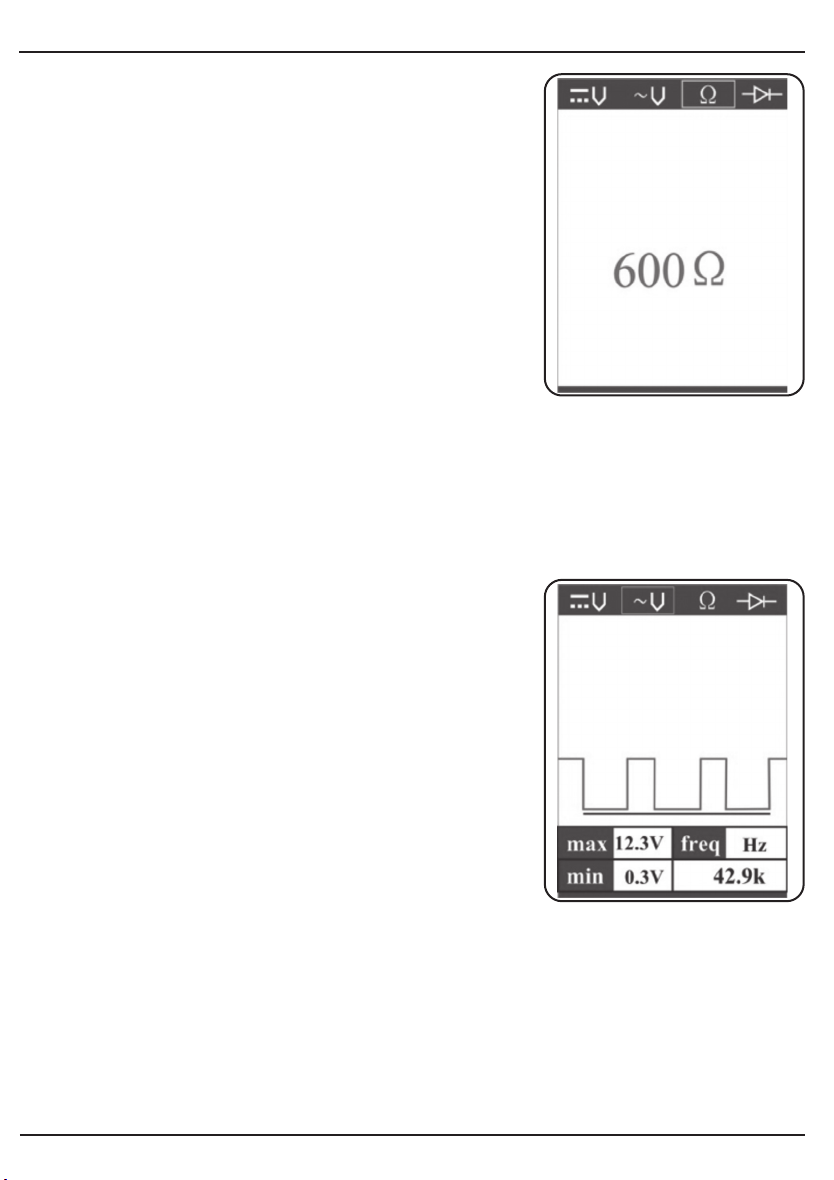
In other cases, the LCD only indicates the resistance
value.
If the resistance value is greater than 100 kΩ, the LCD will show “0L”. There is also another way
to prove continuity of connections to ground or battery. Power up the connection by using the
power switch. If the circuit breaker trips you know that you have a good solid low resistance
connection.
NOTE: You can use the probe tip to pierce the plastic insulation on a wire. This means that you
can test the circuit without disconnecting anything.
9.3 SIGNAL CIRCUIT TESTING - FIG. 16
Once you extract a DTC from the vehicle and realize that
trouble-shooting begins with some kind of sensor circuit,
there is a quick test you can perform to verify the code.
Testing your sensor is easy while using the tool.
For example, you suspect there is a problem with your
M.A.P. Sensor circuit, then follows the procedure
involved with testing this sensor:
• Set the tool in AC Voltage mode, using the probe tip
with chassis ground or the auxiliary ground lead.
• Connect vacuum pump to MAP sensor.
• Contact the probe tip to the MAP sensor positive
terminal and observe the LCD readings which should
be a sine wave in normal condition.
• Apply vacuum.
• Release vacuum and observe the LCD readings.
If the LCD readings are abnormal, there is a problem
with this sensor.
FIG.16
FIG.15
Loading ...
Loading ...
Loading ...