EN
W415-1476 / A / 09.30.16
FR
PG
41
INSTALLER: LEAVE THIS MANUAL WITH THE APPLIANCE.
CONSUMER: RETAIN THIS MANUAL FOR FUTURE REFERENCE.
NEVER LEAVE CHILDREN OR OTHER AT RISK INDIVIDUALS ALONE WITH THE APPLIANCE.
This wood appliance needs periodic inspection and repair for proper operation. It is against United States federal
regulation to operate this wood appliance in a manner inconsistent with operating instructions in this manual.
INSTALLATION AND
OPERATING INSTRUCTIONS
1.27D
Wolf Steel Ltd., 24 Napoleon Rd., Barrie, ON, L4M 0G8 Canada /
103 Miller Drive, Crittenden, Kentucky, USA, 41030
Phone (705)721-1212 • Fax (705)720-9081 • www.napoleonfi replaces.com • hearth@napoleonproducts.com
SAFETY INFORMATION
!
WARNING
If the information in these instructions is not followed exactly, a
fi re or explosion may result causing property damage, personal
injury or death. Improper installation, adjustment, alteration,
service or maintenance can cause injury or property damage,
bodily injury or even death. Please read entire manual before
you install and use your appliance.
This appliance has not been tested with an unvented gas log
set. To reduce risk of fi re or injury, do not install an unvented
gas log set into the appliance.
- This appliance can be very hot when burning.
- Combustible materials such as fi rewood, wet clothing, etc. placed too close
can catch fi re.
- Children and pets must be kept from touching the appliance when it is hot.
- The chimney must be sound and free of cracks. Before installing this unit,
contact the local building or fi re authority and follow their guidelines.
- Operate only with the door tightly closed.
- Burn wood behind the log retainer directly on the fi rebricks.
- Do not use an elevated grate or otherwise raise the fi re.
- At least 14 square inches (90.3 square centimeters) of outside air must be
admitted to the room or directly to the unit through a 4” (101.6mm) diameter
pipe.
- This appliance is designed to burn natural wood only. Higher effi ciencies and
lower emissions generally result when burning air dried seasoned hardwoods,
as compared to softwoods or to green or freshly cut hardwoods.
- Do not start a fi re with chemicals or fl uids such as gasoline, engine oil, etc.
- Do not burn trash or garbage, lawn clippings / waste, rubber, waste petroleum
products, paints or paint thinners / solvents, plastic, materials containing
asbestos, construction debris, railroad ties or treated wood, manure or animal
remains, salt water driftwood or salted materials, unseasoned wood, coal,
charcoal, coloured paper, cardboard, plywood or particleboard.
- Do not let the appliance become hot enough for any part to glow red.
- KEEP THE STOVE TOP TEMPERATURE BELOW 700°F (371°C). Attempts to
achieve heat output rates that exceed design specifi cations can result in steel
distortion and damage.
$10.00
HOT GLASS WILL CAUSE
BURNS.
DO NOT TOUCH GLASS UNTIL
COOLED.
NEVER ALLOW CHILDREN TO
TOUCH GLASS.
!
WARNING
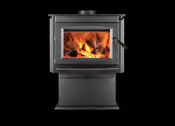
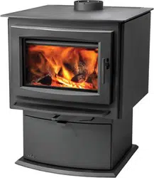
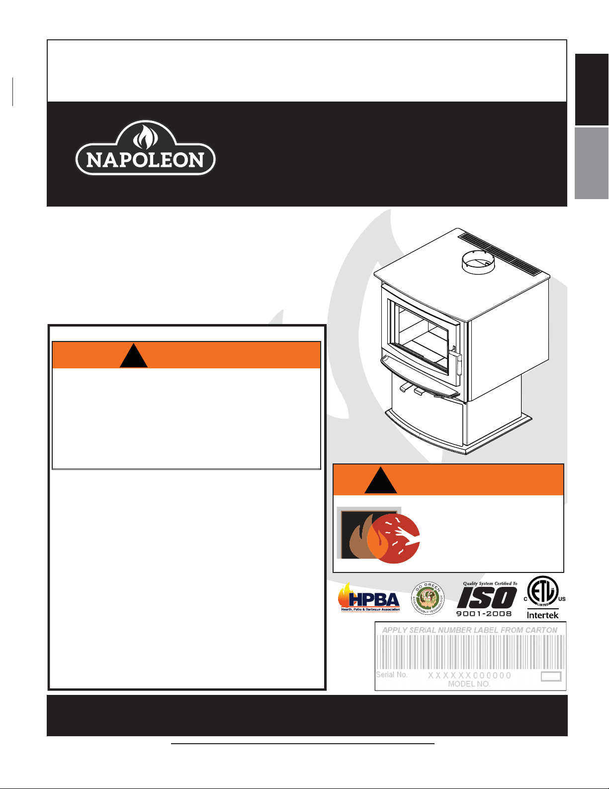
S1, S4 & S9
PEDESTAL MODELS
S
4
ILLU
STRATED
MODEL S1, S4 & S9 MEET THE 2015 U.S ENVIRONMENTAL PROTECTION AGENCY (E.P.A.) CRIB WOOD EMISSION LIMITS FOR WOOD STOVES SOLD AFTER
MAY 15, 2015, 40 C.F. R. PART 60. THESE STOVES HAVE BEEN TESTED AND LISTED BY INTERTEK TESTING SERVICES TO STANDARDS: CSA B366.2,
ULC S627, UL 1482.

W415-1476 / A / 09.30.16
2
EN
NOTE: Changes, other than editorial, are denoted by a vertical line in the margin.
TABLE OF CONTENTS
1.0 INSTALLATION OVERVIEW 3
2.0 INTRODUCTION 4
2.1 DIMENSIONS 5
2.3 SPECIFICATIONS 6
2.2 GENERAL INSTRUCTIONS 6
2.4 GENERAL INFORMATION 7
2.5 RATING PLATE INFORMATION 8
3.0 PRE-INSTALLATION PREPARATION 9
3.1 APPLIANCE PLACEMENT 9
3.2 CLEARANCE TO COMBUSTIBLES 9
3.3 FLOOR PROTECTION 10
3.4 OUTSIDE AIR 10
3.4.1 OUTSIDE AIR - MOBILE HOME 10
4.4.1 MOBILE HOME 11
4.0 INSTALLATION 11
4.1 CHIMNEY 12
4.1.1 CHIMNEY CONNECTION 13
4.1.2 SECTIONS 14
4.1.3 TYPICAL THROUGH THE CEILING 15
4.1.4 TYPICAL THROUGH THE WALL 16
4.1.5 TYPICAL EXISTING MASONRY 16
5.0 FINISHING 17
5.1 DOOR REMOVAL / INSTALLATION 17
5.1.1 DOOR ADJUSTMENT 17
5.1.2 LATCH BLOCK HOUSING ADJUSTMENT 17
5.2 HANDLE AND DOOR SERVICE AND INSTALLATION 18
5.3 BRICKS AND BAFFLE INSTALLATION 19
5.4 ASH DRAWER ADJUSTMENT 20
6.0 OPTIONAL KIT INSTALLATIONS 21
6.1 BLOWER KIT INSTALLATION 21
6.1.1 BLOWER INSTALLATION 21
6.2 DOOR TRIM KIT 22
7.0 OPERATION 22
7.1 OPTIMUM BURN METHOD 24
7.2 AIR CONTROL 24
7.3 FIRE EXTINGUISHERS / SMOKE & CARBON MONOXIDE DETECTORS 24
7.4 FUEL 25
7.5 LIGHTING A FIRE 25
7.5.1 FLASH FIRE 25
7.5.2 EXTENDED FIRE 25
7.6 SMOKING 26
8.0 MAINTENANCE 26
8.1 ASH REMOVAL PROCEDURES 26
8.2 CREOSOTE FORMATION AND REMOVAL 27
8.3 RUNAWAY OR CHIMNEY FIRE 27
8.4 CHIMNEY CLEANING 27
8.5 GLASS REPLACEMENT 28
8.6 SECONDARY AIR MANIFOLD REPLACEMENT 29
8.7 CARE OF GLASS 30
8.8 CARE OF PLATED PARTS 30
8.9 WOOD 31
9.0 REPLACEMENTS 32
9.1 S1 OVERVIEW 33
9.2 S4 OVERVIEW 34
9.3 S9 OVERVIEW 35
9.4 S1, S4 & S9 DOOR ASSEMBLY 36
10.0 S1, S4 & S9 ACCESSORIES 37
11.0 TROUBLESHOOTING 38
12.0 WARRANTY 39
NOTE: The camera icon indicates video tutorials are available as additional reference,
visit http://mynapoleon.napoleonproducts.com/download/index/44/1
W415-1476 / A / 09.30.16
3
EN
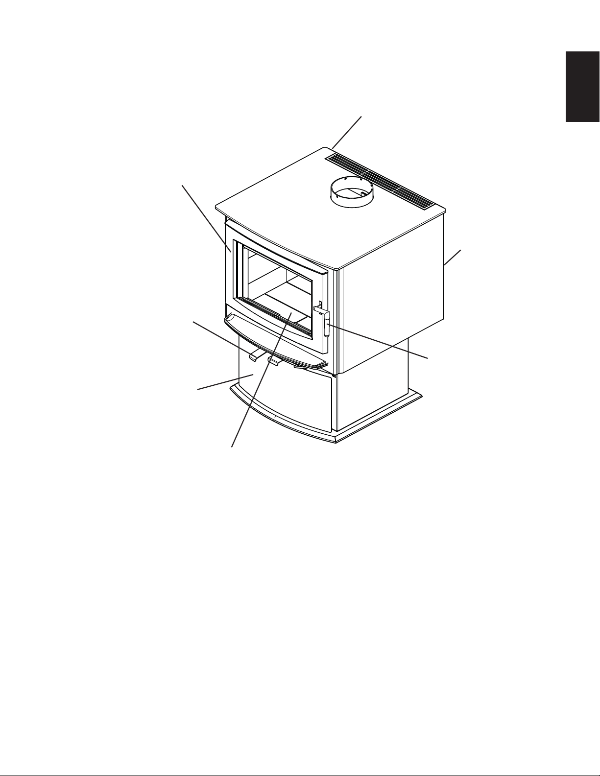
1.0 INSTALLATION OVERVIEW
Rating plate, see “RATING
PLATE INFORMATION ”
section.
Blower, see
“OPTIONAL
BLOWER KIT
INSTALLATION”
section.
Handle, see “DOOR AND
HANDLE INSTALLATION
AND SERVICE” section.
Brick and baffles, see
“BRICK AND BAFFLE
INSTALLATION” section.
Draft, see “AIR
CONTROL”
section.
Door, see “DOOR REMOVAL
AND INSTALLATION” section.
S
4
I
L
LU
S
T
R
A
T
E
D
Ash drawer, see “ASH
DRAWER ADJUSTMENT”
section.

W415-1476 / A / 09.30.16
4
EN
2.0 INTRODUCTION
3.17G
!
WARNING
• THIS APPLIANCE IS HOT WHEN OPERATED AND CAN CAUSE SEVERE BURNS IF CONTACTED.
• ANY CHANGES OR ALTERATIONS TO THIS APPLIANCE OR ITS CONTROLS CAN BE DANGEROUS AND
IS PROHIBITED.
• Do not operate appliance before reading and understanding operating instructions. Failure to operate appliance
according to operating instructions could cause fi re or injury.
• Before installing this appliance, contact the local building or fi re authority and follow their guidelines.
• This appliance must be installed by a qualifi ed installer.
• Risk of burns. The appliance should be turned off and cooled before servicing.
• Do not operate without fully assembling all components.
• Do not let the appliance become hot enough for any part to glow red.
• Do not install damaged, incomplete or substitute components.
• Risk of cuts and abrasions. Wear protective gloves and safety glasses during installation. Sheet metal edges may
be sharp.
• Children and adults should be alerted to the hazards of high surface temperature and should stay away to avoid
burns or clothing ignition.
• Young children should be carefully supervised when they are in the same room as the appliance. Toddlers, young
children and others may be susceptible to accidental contact burns. A physical barrier is recommended if there
are at risk individuals in the house. To restrict access to an appliance or stove, install an adjustable safety gate to
keep toddlers, young children and other at risk individuals out of the room and away from hot surfaces.
• Clothing or other fl ammable material should not be placed on or near the appliance. Objects placed in front of the
appliance must be kept a minimum of 4 feet (1.2m) away from the front face of the appliance.
• Due to high temperatures, the appliance should be located out of traffi c and away from furniture and draperies.
• Ensure you have incorporated adequate safety measures to protect infants/toddlers from touching hot surfaces.
• Even after the appliance is out, the glass and/or screen will remain hot for an extended period of time.
• Check with your local hearth specialty dealer for safety screens and hearth guards to protect children from hot
surfaces. These screens and guards must be fastened to the fl oor.
• Any safety screen or guard removed for servicing must be replaced prior to operating the appliance.
• Under no circumstances should this appliance be modifi ed.
• This appliance must not be connected to a chimney fl ue pipe servicing a separate solid fuel burning appliance.
• Do not operate the appliance with the glass door removed, cracked or broken. Replacement of the glass should
be done by a licensed or qualifi ed service person.
• Do not strike or slam shut the appliance glass door.
• Only doors / optional fronts certifi ed with the appliance are to be installed on the appliance.
• Keep the packaging material out of reach of children and dispose of the material in a safe manner. As with all
plastic bags, these are not toys and should be kept away from children and infants.
• If the appliance is not properly installed, a house fi re may result. Do not expose the appliance to the elements (ex.
rain, etc.) and keep the appliance dry at all times. Wet insulation will produce an odour when the appliance is used.
• The chimney must be sound and free of cracks. Clean your chimney a minimum of twice a year and as required.
• Do not start a fi re with chemicals or fl uids such as gasoline, engine oil, etc.
• Your appliance requires periodic maintenance and cleaning. Failure to maintain your appliance may lead to smoke
spillage in your home.
• Lower emissions generally result when burning air dried seasoned hardwoods, as compared to softwoods or too
green or freshly cut hardwoods. Burning wet unseasoned wood can cause excessive creosote accumulation.
When this is ignited it can cause a chimney fi re that may result in a serious house fi re.
• This appliance is designed to burn natural wood only. Do not burn trash or garbage, lawn clippings / waste,
rubber, waste petroleum products, paints or paint thinners / solvents, plastic, materials containing asbestos,
construction debris, railroad ties or treated wood, manure or animal remains, salt water driftwood or salted
materials, unseasoned wood, coal, charcoal, coloured paper, gift wrapping, cardboard, plywood or particleboard.
Burning these materials may result in release of toxic fumes or render the appliance ineffective and cause smoke.
• Burn wood directly on the fi rebricks. Do not elevate grate or otherwise raise the fi re.
• Do not store wood within appliance installation clearances or within the space required for re-fueling and ash removal.
• Ashes must be disposed in a metal container with a tight lid and placed on a non-combustible surface well away
from the home or structure until completely cool.
• Ensure clearances to combustibles are maintained when building a mantel or shelves above the appliance.
Elevated temperatures on the wall or in the air above the appliance can cause melting, discolouration or damage to
decorations, a T.V. or other electronic components.
• If equipped, the catalyst must be installed and in good working order. It is recommended that the catalyst is
inspected at least 3 times per heating season.
W415-1476 / A / 09.30.16
5
EN
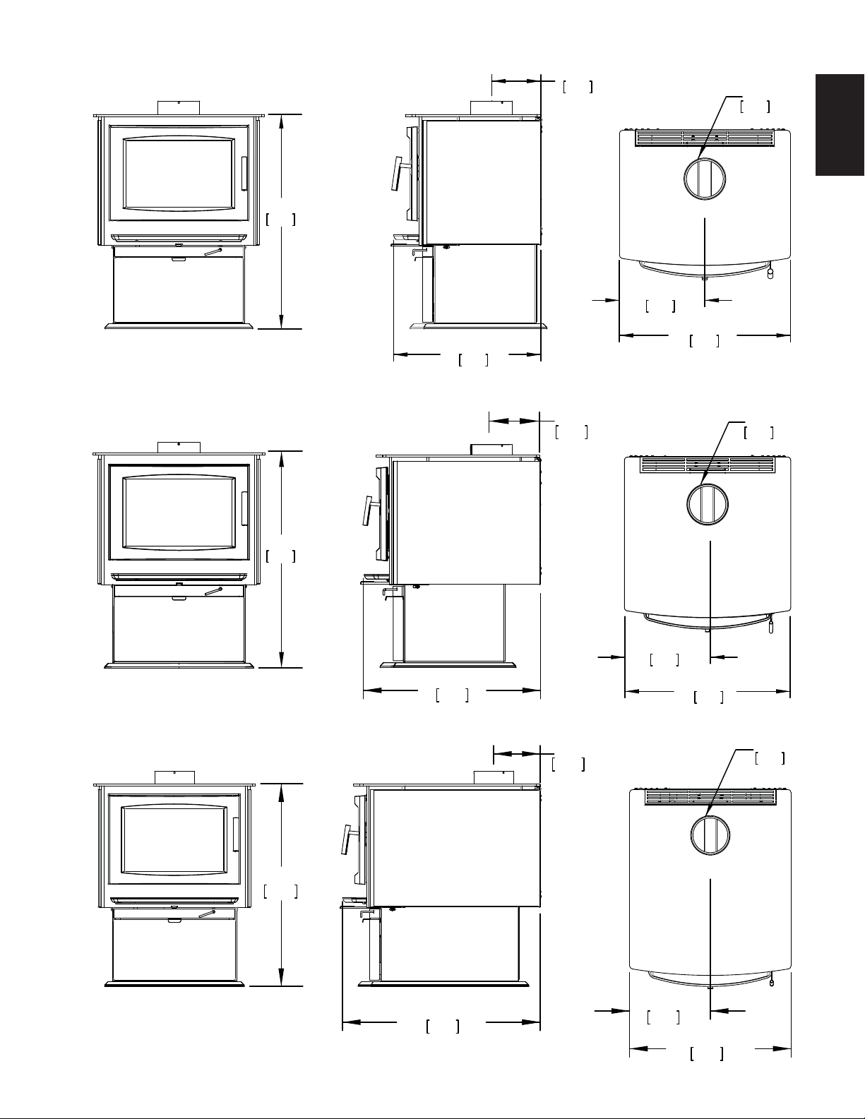
7 1/4"
184mm
22”
559mm
Ø
6 "
152mm
12 3/4"
324mm
25 1/2"
648mm
31 1/4"
793mm
7 3/8"
187mm
26 1/2"
673mm
7 1/4"
184mm
25 1/2"
648mm
12 3/4"
324mm
Ø
6 "
152mm
32"
812mm
S1 ILLUSTRATED
25 1/2"
648mm
12 3/4"
324mm
Ø
6 "
152mm
S4 ILLUSTRATED
32"
812mm
32"
812mm
S9 ILLUSTRATED
2.1 DIMENSIONS
W415-1476 / A / 09.30.16
6
EN
2.2 GENERAL INSTRUCTIONS
4.7
ALL WIRING SHOULD BE DONE BY A QUALIFIED ELECTRICIAN AND SHALL BE IN COMPLIANCE WITH
LOCAL CODES. IN THE ABSENCE OF LOCAL CODES, USE THE CURRENT CSA22.1 CANADIAN
ELECTRIC CODE IN CANADA OR THE CURRENT NATIONAL ELECTRIC CODE ANSI/NFPA NO. 70 IN
THE UNITED STATES.
THIS APPLIANCE HAS NOT BEEN TESTED WITH ANY VENTED OR UNVENTED GAS LOG SET. TO
REDUCE RISK OF FIRE OR PREVENT INJURY, DO NOT INSTALL A VENTED OR UNVENTED GAS LOG
SET INTO THE APPLIANCE.
BURNING YOUR UNIT WITH THE ASH DUMP DOOR OPEN OR AJAR CREATES A FIRE HAZARD THAT
MAY RESULT IN DISCOLOURATION TO THE GOLD PLATED DOOR, INTERNAL DAMAGE TO THE
APPLIANCE OR A HOUSE CHIMNEY FIRE.
DO NOT CONNECT THIS APPLIANCE TO A CHIMNEY FLUE SERVING ANOTHER APPLIANCE.
THIS APPLIANCE AND IT’S COMPONENTS ARE DESIGNED TO BE INSTALLED AND OPERATED AS A
SYSTEM. ANY ALTERATION TO OR SUBSTITUTION FOR ITEMS IN THIS SYSTEM, UNLESS ALLOWED
BY THESE INSTALLATION INSTRUCTIONS, WILL VOID THE LISTING AND MAY VOID THE PRODUCT
WARRANTY. IT MAY ALSO CREATE A HAZARDOUS INSTALLATION. READ THROUGH THESE
INSTRUCTIONS THOROUGHLY BEFORE STARTING YOUR INSTALLATION AND FOLLOW THEM
CAREFULLY THROUGHOUT YOUR PROJECT.
!
WARNING
• Before beginning your installation, consult with your local building code agency or fi re offi cials and
insurance representative to ensure compliance.
• Non-toxic smoke will be emitted during the paint curing process, to help dissipate the smoke open a
window near the appliance.
• Remove any dust or debris off the top of the appliance before fi ring the appliance as the paint will
become soft as the appliance heats up and will harden as the appliance cures. To cure the paint on your
appliance burn your appliance moderately hot during the fi rst few fi res.
• To keep the gasket from sticking to the appliance as the paint is curing, periodically open the door every
5-10 minutes.
• For the fi rst two weeks use generous amounts of fuel and burn the appliance with the damper wide
open for an hour as the appliance goes through a process of eliminating moisture in the fi rebricks. The
initial heat output will be reduced while the moisture is being drawn from the appliance and it will be
necessary to build several hot fi res to remove this moisture. DURING THIS PROCESS DO NOT OVER
FIRE THE APPLIANCE. REDUCE THE AMOUNT OF AIR COMING INTO THE APPLIANCE IF THE
APPLIANCE OR CHIMNEY BECOMES RED.
SPECIFICATIONS S1 S4 S9
FIREBOX CHAMBER 13 1/2”x18”x12”
(34.3cmx45.7cmx30.5cm)
18”x18”x12”
(45.7cmx45.7cmx30.5cm)
22 1/2”x18”x12”
(57.2cmx45.7cmx30.5cm)
CAPACITY 1.7 ft
3
(0.05m
3
) 2.25 ft
3
(0.06m
3
) 3.0 ft
3
(0.09m
3
)
APPROX. AREA HEATED** 600-1500 ft
2
(56-139m
2
)
1000-2000 ft
2
(93-186m
2
)
1000-3500 ft
2
(93-325m
2
)
MAXIMUM HEAT OUTPUT*** 55,000 BTU/ Hr 70,000 BTU/ Hr 85,000 BTU/ Hr
HEAT OUTPUT* 11,700 - 42,200 BTU/ Hr 11,400 - 41,300 BTU/ Hr 11,800 - 34,000 BTU/ Hr
DURATION LOW FIRE* 7 Hours 9 Hours 12 Hours
WEIGHT w/o BRICKS 215 lbs (98kg) 250 lbs (113.4kg) 285 lbs (129kg)
WEIGHT OF BRICKS 110 lbs (50kg) 145 lbs (65.8kg) 114 lbs (52kg)
IDEAL WOOD LENGTH
(WHEN END LOADED)
12” (30.5cm) 16” (40.6cm) 21” (53.3cm)
* As tested using test method 28
** Figures will vary considerably with individual conditions.
*** Wolf Steel Ltd. estimated realistic BTU/hr with hardwood logs and regular refueling.
2.3 SPECIFICATIONS
W415-1476 / A / 09.30.16
7
EN
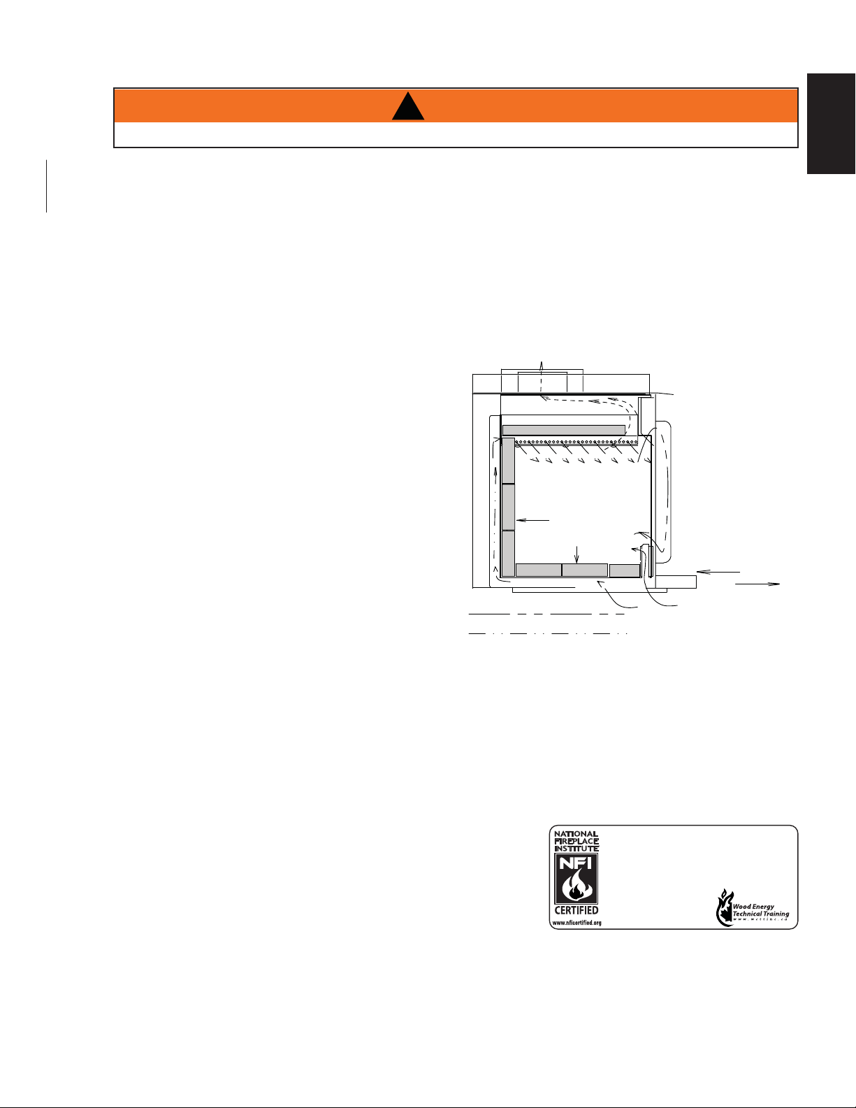
Your appliance has been specifi cally designed to meet the 2015 U.S.A. EPA particulate emission standards and
has been extensively tested in Canadian and American laboratories. This system is the most effi cient, simple and
trouble free we know and works as follows:
The chimney vent system used on your wood burning appliance should be designed with the least amount of
restriction possible to enable the exhaust products to easily fl ow through it. Chimney vent systems that are too
short or too long can also have an adverse affect on the fl ow of exhaust through it. The wood burning appliance
and chimney vent system also require a suffi cient supply of combustion air not only to support the combustion in
the combustion chamber but to replace the exhaust leaving it so it can fl ow freely up through the vent system and
out into the atmosphere. It is the correct balance of combustion air and the chimney vent system that will ensure
the appliance provides you with its optimum performance.
Combustion air enters through two holes in the bottom
which can be adjusted by a single air control. Air from
the front hole goes up on either side of the door into
a preheating airwash located across the top and then
down the window to feed the fi re and also to ensure that
the glass remains clean. Air from this hole also feeds
directly into the combustion chamber at hearth level.
Secondary air from the rear hole travels up the back in
the secondary air housing to the manifold located at the
top and shoots out laterally to oxidize the gases below
the smoke exit.
The combustion chamber is lined with high temperature
fi rebrick on 2 sides, the back and across the bottom,
with a layer of fi bre baffl es at the top to maintain a high
temperature in the combustion chamber so that gases
mixing with the preheated air from the secondary air
manifold tube are easily ignited and burned. The stove
sides and back are shielded to direct the heat upwards
and forwards into the room.
Be sure to provide suffi cient combustion air. There are many other appliances in your home competing for air such
as: a kitchen range hood, forced air heating devices or a bathroom exhaust fan.
Expansion / contraction noises during heating up and cooling down cycles are normal and to be expected.
After extended periods of non-operation such as following a vacation or a warm weather season, the appliance
may emit a slight odour for a few hours. This is caused by dust particles on the fi rebox burning off. Open a window
to suffi ciently ventilate the room.
CALIFORNIA PROP 65 WARNING:
Use of this product may produce smoke which contains chemicals
known to the State of California to cause cancer, birth defects, or other
reproductive harm.
If the outside air feature of the stove is utilized, you should never
experience a shortage of combustion air. If you choose not to utilize outside air and experience draft or smoking
problems, you may need to open a door or window.
To ensure that the ash dump door is tightly closed, allow the door to snap shut dislodging anything (ashes or
pieces of coal) that may be stuck in the opening.
HOT SECONDARY AIR
FIBRE BRICKS
REFRACTORY
2 SIDES, BACK
& BOTTOM
SECONDARY AIR
PRIMARY AIR
FLUE GLASS
CERAMIC
GLASS
AIR CONTROL
COMBUSTION AIR
INTAKE
OPEN
CLOSED
2.4 GENERAL INFORMATION
DO NOT OPERATE THIS APPLIANCE WITHOUT THE PEDESTAL INSTALLED.
!
WARNING
We suggest that our woodburning hearth products
be installed and serviced by professionals who are
certified in the U.S. by the National Fireplace
Institute® (NFI) as NFI Woodburning Specialists or
who are certified in Canada by
Wood Energy Technical
Training (WETT).
W415-1476 / A / 09.30.16
8
EN
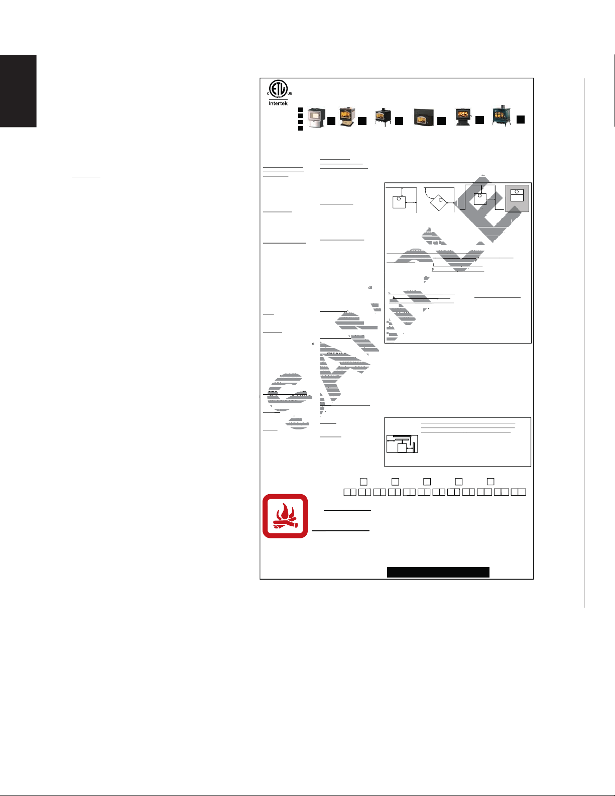
2.5 RATING PLATE INFORMATION
For rating plate location, see
“INSTALLATION OVERVIEW” section.
This illustration is for reference only.
Refer to the rating plate on the
appliance for accurate information.
NOTE: The rating plate must
remain with the appliance at all
times. It must not be removed.
LISTED SOLID FUEL BURNING FIREPLACE INSERT /
ENCASTRÉ À COMBUSTIBLE SOLIDE HOMOLOGUÉ
TESTED TO / TESTÉ SELON :
ULC S628 / UL 1482
FROM HEATER / DU POÊLE
RESIDENTIAL / RÉSIDENTIEL
S4
16IN/PO (406 mm)
12IN/PO (305 mm)
6IN/PO (152 mm)
USING DOUBLE WALL CONNECTOR /
UTILISATION D’UN CONDUIT DE
RACCORDEMENT À DOUBLE PAROI
MAISON / MOBILE HOME*
S4
1400
16IN/PO (406 mm)
10IN/PO (254 mm)
6IN/PO (152 mm)
6IN/PO (152 mm)
4IN/PO (102 mm)
4IN/PO (102 mm)
EPI 1402
INSTALL AND USE ONLY IN
ACCORDANCE WITH THE
MANUFACTURER’S
INSTRUCTIONS AND LOCAL
BUILDING CODES.
MINIMUM CEILING HEIGHT:
7FT (2.13m)
HEARTH EXTENSION /
COMBUSTIBLE FLOOR
PROTECTION: IF INSTALLED
ON A COMBUSTIBLE FLOOR,
UNIT MUST BE PLACED ON A
NON-COMBUSTIBLE FLOOR
PROTECTOR EXTENDING 18”
(455mm) IN FRONT AND 8”
(205mm) TO THE SIDES AND
BACK.
CHIMNEY TYPE: MINIMUM 6”
(152mm) DIAMETER
APPROVED RESIDENTIAL
TYPE FOR MOBILE HOME USE
A CHIMNEY LISTED TO ULC
S629 IN CANADA OR UL 103HT
IN THE USA.
CHIMNEY CONNECTOR: 6”
(152mm) DIAMETER MINIMUM
24 GAUGE STEEL MINIMUM
CLEARANCE FROM
HORIZONTAL CONNECTOR
AND CEILING 18” (455mm).
DO NOT OBSTRUCT SPACE
UNDER HEATER.
SPECIAL METHODS ARE
REQUIRED WHEN PASSING A
CHIMNEY THROUGH A WALL
OR CEILING. SEE INSTRUC-
TIONS AND BUILDING CODES.
DO NOT CONNECT THIS UNIT
TO A CHIMNEY FLUE SERVING
ANOTHER APPLIANCE.
FUEL: FOR USE WITH WOOD
ONLY. DO NOT USE GRATE OR
ELEVATE FIRE. BUILD WOOD
FIRE DIRECTLY ON HEARTH.
WARNING: RISK OF SMOKE
SPILLAGE. OPERATE ONLY
WITH DOOR FULLY CLOSED.
REPLACE GLASS ONLY WITH
CERAMIC GLASS.
DO NOT OVERFIRE. IF
HEATER OR CHIMNEY
CONNECTORS GLOW, YOU
ARE OVERFIRING. INSPECT
AND CLEAN CHIMNEY
FREQUENTLY. UNDER
CERTAIN CONDITIONS OF
USE CREOSOTE BUILD-UP
MAY OCCUR RAPIDLY.
OPTIONAL BLOWER KIT:
EP-62, 115V, 60HZ, 0.82AMP.
ROUTE CORD AWAY FROM
UNIT.
DANGER: RISK OF
ELECTRICAL SHOCK.
DISCONNECT POWER
BEFORE SERVICING UNIT.
INSERT: INSTALL AND USE
ONLY IN SOLID FUEL
BURNING FIREPLACES. DO
NOT REMOVE BRICKS OR
MORTAR FROM SOLID FUEL
BURNING FIREPLACE.
INSTALL WITH A POSITIVE
FLUE CONNECTOR AND
FACEPLATE.
POUR INSTALLATION ET
UTILISATION CONFORM
ÉMENT AUX
INSTRUCTIONS DU FABRICANT ET
AUX CODES LOCAUX DU BÂTIMENT.
HAUTEUR DE PLAFOND MINIMAL
7PI (2,13m).
PROLONGEMENT
D’ÂTRE/PROTECTION DU
PLANCHER COMBUSTIBLE: SI
INSTALL
É SUR UN PLANCHER
COMBUSTIBLE, L’APPAREIL DOIT
ÊTRE PLAC
É SUR UNE PLAQUE
PROTECTRICE INCOMBUSTIBLE
S’ÉTENDANT SUR 18” (455mm)
À
L’AVANT ET 8” (205mm) À L’ARRIÈRE
ET SUR LES CÔTÉS.
TYPE DE CHIMNÉE: DIAMÈTRE
MINIMAL DE 6” (152mm)
APPROUVÉE POUR USAGE
RÉSIDENTIEL. MAISON MOBILE
EMPLOYEZ UNE CHEMINÉE
HOMOLOGUÉE ULC S629 AU
CANADA OU UL 103HT AUX
ÉTATS-UNIS.
RACCORD DE CHEMINÉE:
DIAMÈTRE DE 6” (152mm) D’ACIER
DE CALIBRE 24 MINIMUM. 18”
(455mm) DE DÉGAGEMENT MINIMAL
ENTRE LE RACCORD HORIZONTAL
ET LE PLAFOND.
NE RIEN ENTREPOSER SOUS
L’APPAREIL.
DES MÉTHODES SPÉCIALES SONT
REQUISES LORSQU’UNE CHEMINÉE
TRAVERSE UN MUR OU UN
PLAFOND. VOIR LES INSTRUC-
TIONS ET LES CODES DU
BÂTIMENT.
NE PAS RACCORDER À LA
CHEMINÉE D’UN AUTRE APPAREIL.
COMBUSTIBLE: POUR USAGE AVEC
LE BOIS SEULEMENT. N’UTILISEZ
PAS DE CHENET OU NE
SURÉLEVEZ PAS LE BOIS.
PRÉPAREZ LE FEU DIRECTEMENT
SUR L’ÂTRE.
AVERTISSEMENT: RISQUE
D’ÉCHAPPEMENT DE FUMÉE. TENIR
LA PORTE FERMÉE LORSQUE LE
POÊLE FONCTIONNE. REMPLACEZ
LA VITRE PAR UNE VITRE EN
CÉRAMIQUE SEULEMENT.
NE SURCHAUFFEZ PAS L’APPAREIL.
SI L’APPAREIL OU LES RACCORDS
ROUGEOIENT, L’APPAREIL
SURCHAUFEE. INSPECTEZ ET
NETTOYEZ LA CHEMINÉE
FRÉQUEMMENT. DANS CERTAINES
CONDITIONS, DES DÉPÔTS DE
CRÉOSOTE PEUVENT SE FORMER
RAPIDEMENT.
SOUFFLERIE OPTIONNELLE: EP-62,
115V, 60HZ, 0,82A. TENEZ LE
CORDON ÉLECTRIQUE LOIN DE
L’APPAREIL.
DANGER: RISQUE DE SECOUSSE
ÉLECTRIQUE. DÉBRANCHEZ AVANT
DE PROCÉDER À L’ENTRETIEN.
ENCASTRÉ: INSTALLEZ ET UTILISEZ
SEULEMENT DANS UN FOYER À
COMBUSTIBLE SOLIDE. NE RETIREZ
PAS DE MORTIER, NI BRIQUES DU
FOYER À COMBUSTIBLE SOLIDE.
INSTALLEZ AVEC UNE GAINE
CONFORME ET UNE PLAQUE DE
RECOUVREMENT.
CONTACT LOCAL BUILDING FIRE OFFICIALS ABOUT RESTRICTIONS AND
INSTALLATION INSPECTION IN YOUR AREA. MODEL 1400 IS SUITABLE FOR USE
IN MOBILE HOMES WHEN USED WITH OUTSIDE AIR INSTALLATION KIT (111KT).
A MINIMUM CLEARANCE OF 18” (457mm) TO THE CHIMNEY CONNECTOR MAY
BE REQUIRED BY THE AUTHORITY HAVING JURISDICTION.
RENSEIGNEZ-VOUS AUPR
ÈS DES AUTORITÉS LOCALES DU BÂTIMENT ET DU
SERVICE DES INCENDIES AU SUJET DES RESTRICTIONS ET DES INSPECTIONS
D’INSTALLATION DANS VOTRE RÉGION. LES MODÈLES 1400 PEUVENT ÊTRE
INSTALLÉS DANS UNE MAISON MOBILE SI INSTALLÉS CONJOINTEMENT AVEC UNE
PRISE D’AIR EXTÉRIEUR (111KT). UN DÉGAGEMENT MINIMAL DE 18” (457mm)
JUSQU’AU RACCORD DE LA CHEMINÉE PEUT ÊTRE EXIGÉ PAR L’AUTORITÉ AYANT
JURIDICTION.
8"
8"
18"
8"
ALCOVE
A"
B"
C
BACK WALL (M/A)
45°
SIDE WALL (M/L)
BACK WALL (M/A)
SIDE WALL (M/L)
B
A
IF THE STOVE IS TO BE INSTALLED ON A COMBUSTIBLE FLOOR, IT MUST BE
PLACED ON AN APPROVED NON-COMBUSTIBLE HEARTH PAD, THAT
EXTENDS 8” (200mm) BEYOND THE STOVE SIDES AND BACK, AND 18”
(455mm) TO THE FRONT.
SI LE PO
Ê
LE EST INSTALL
É SUR UN PLANCHER COMBUSTIBLE, IL DOIT ÊTRE PLACÉ
SUR UNE BASE DE PROTECTION INCOMBUSTIBLE CERTIFÉE QUI DOIT DÉPASSER
LES CÔTÉS ET L’AMÉRE DU
PO
Ê
LE DE 8” (200mm) ET SE PROLONGER DE 18”
(455mm) SUR LE DEVANT.
MINIMUM CLEARANCE TO COMBUSTIBLE MATERIAL WITH SINGLE WALL
CHIMNEY CONNECTOR / D
ÉGAGEMENTS MINIMAUX AUX MATÉRIAUX
COMBUSTIBLES AVEC RACCORD DE CHEMINÉE À PAROI SIMPLE:
*
MODELS 1400 AND S4 MAY BE INSTALLED INTO A MOBILE HOME IN THE
UNITED STATES ONLY.
*
LE MODÈLES 1400 ET S4 NE PEUT ÊTRE INSTALLÉ QUE DANS UNE MAISON
MOBILE AUX ÉTATS-UNIS SEULEMENT.
HOT WHILE IN OPERATION. DO NOT TOUCH. KEEP CHILDREN,
CLOTHING AND FURNITURE AWAY. CONTACT MAY CAUSE
SKIN BURNS.
QUAND L’APPAREIL FONCTIONNE, LA SURFACE DEVIENT
CHAUDE. NE PAS TOUCHER. TENIR LES ENFANTS, LES
VÊTEMENTS ET LES MEUBLES À L’ÉCART. LE CONTACT PEUT
CAUSER DES BRÛLURES À LA PEAU.
CAUTION:
ATTENTION:
W385-2031 / A
EPA1400
1400 1400L 1402
1450
S4
WOLF STEEL LTD.
24 NAPOLEON ROAD, BARRIE, ON, L4M 0G8 CANADA
1400C
9700539 (WSL)
4001657 (NGZ)
4001658 (NAC)
4001659 (WUSA)
LISTED SOLID FUEL BURNING SPACE HEATER / POÊLE À COMBUSTIBLE SOLIDE
HOMOLOGUÉ TESTED TO: / TESTÉ SELON : UL1482 / ULC S627
MODEL / MODÈLE - EPA 1400
U.S. ENVIRONMENTAL PROTECTION AGENCY
U.S
.ENVIRO
N
ME
NTAL
P
ROT
E
CTION AGE
NCY
Certified to comply with 2015 particulate emissions standards. Not approved for sale
Ce
r
tified to c
o
mpl
ywi
t
h
2015par
ticul
ate emi
ssi
ons s
ta
ndar
d
s
.No
t
a
pprove
dfors
a
l
e
after May 15, 2020. Certifié conforme à la norme d’ émanation de particles de 2020. Non approuvé pour la vente après le 15 mai,
2020.
af
t
er May 15, 2020. Cert
i
fi
é
c
o
nforme àl
a
normed’
é
ma
nation de partic
l
es
d
e2020. Non appr
o
uvé pour
l
av
en
te apr
è
sle
15 mai
,2020
.
40 CFR Part 60,Subpart AAA.
4
0CFRPar
t60,S
u
bpart A
A
A
.
1400
12IN/PO (305 mm)
12IN/PO (305 mm)
6IN/PO (152 mm)
1400
10IN/PO (254 mm)
6IN/PO (152 mm)
4IN/PO (102 mm)
S4
16IN/PO (406 mm)
6IN/PO (152 mm)
4IN/PO (102mm)
CEILING / PLAFOND
C
D
B
A
FLOOR / PLANCHER
CLEARANCES TO COMBUSTIBLE CONSTRUCTION /
D
ÉGAGEMENTS AUX MATÉRIAUX COMBUSTIBLES:
(MEASURED TO UNIT / À PARTIR DE L’APPAREIL)
A SIDE FACING / CÔTÉ 1 IN/PO (25mm)
*
B TOP FACING / DESSUS 28 IN/PO (710mm)
C MANTEL / TABLETTE 28 IN/PO (710mm)
D SIDE WALL / MUR LATÉRAL 17 IN/PO (430mm)
*
CLEARANCE TO EDGE OF FLASHING / DÉGAGEMENT AU
BORD DE LA FAÇADE
3.5 Grams Per Hour / 2015 Crib Wood / 3.5 Grammes par heure / Crib Wood 2015
3.5
Grams Pe
r
Ho
ur
/2
0
15 Cri
bW
ood / 3.5 Grammes
p
ar heure / Cri
bWoo
d201
5
MANUFACTURE DATE: / DATE DE FABRICATION:
YEAR:
2016
2017
2018
MONTH:
2019
2020
24365871091211
1
THIS WOOD APPLIANCE NEEDS PERIODIC INSPECTION AND REPAIR FOR
PROPER OPERATION. CONSULT THE OWNER'S MANUAL FOR FURTHER
INFORMATION. IT IS AGAINST UNITED STATES FEDERAL REGULATIONS TO
OPERATE THIS WOOD APPLIANCE IN A MANNER INCONSISTENT WITH THE
OPERATING INSTRUCTIONS IN THE OWNER'S MANUAL.
CET APPAREIL AU BOIS DOIT FAIRE L'OBJECT D'UNE INSPECTION ET D'UN
ENTRETIEN PÉRIODIQUES POUR UN FONCTIONNEMENT ADÉQUAT. CONSULTEZ
LE MANUEL D'INSTRUCTIONS POUR PLUS D'INFORMATION. LES RÈGLEMENTS
FÉDÉRAUX DE L'ÉTATS-UNIS INTERDISENT D'UTILISER CET APPAREIL DE
CHAUFFAGE D'UNE MANIÈRE ALLANT À L'ENCONTRE DES INSTRUCTIONS DE
FONCTIONNEMENT CONTENUES DANS CE MANUEL.
SAMPLE
S
FROM HEATER / DU POFROM HEATER / DU P
PL
RESIDENTIAL / RÉSIDRESIDENTIAL / RÉS
PL
USING DOUBLE WALL CONNECTUSING DOUBLE WA
MP
UTILISATION D’UN CONDUIUTILISATION D’UN C
MP
RACCORDEMENT À DOUBLRACCORDEMENT À DO
MP
16IN16
THTH
F
NEY
GLOW, YOU
RING. INSPECT
N CHIMNEY
NTLY. UNDERNTLY. UNDER
AIN CONDITIONS OFAIN CONDITIONS
E CREOSOTE BUILD-UP CREOSOTE BU
MAY OCCUR RAPIDLY.
AY OCCUR RAPIDLY.
OPTIONAL BLOWER KIT:
PTIONAL BLOWER KIT:
SA
EP-62, 115V, 60HZ, 0.82AMP.
P-62, 115V, 60HZ, 0.82AMP.
ROUTE CORD AWAY FROM
OUTE CORD AWAY FRO
NIT.
T.
GER:ER:
RI
S
K
O
F
RISK
S
RICAL SHOCK. OC
ECT POWERPOWER
RVICING UNIT.RVICING UNIT.
LL AND USE
LLAND US
UEL
CE
NÉE
UC-UC-
U
ER À LA
AUTRE APPAREIL.REIL.
E::
POUR USAGE AVEC POUR USAGE AVEC
M
ULEMENT. N’UTILISEZ ULEMENT. N’UTILISEZ
CHENET OU NEHENET OU NE
LEVEZ PAS LE BOIS.VEZ PAS LE BOIS.
ÉPAREZ LE FEU DIRECTEMENT LE FEU DIRECTEMENT
SUR L’ÂTRE.
AVERTISSEMENT:T:
R
IS
Q
U
ERISQUE
AM
D’É
C
HAPPEMENT DE F
U
MÉE. TENIR
D’ÉCHAPPEMENT DE FUMÉE. T
LA PORTE FERMÉE LORS
Q
UE LE
LA PORTE FERMÉE LORSQUE LE
P
O
ÊLE F
O
N
C
TI
O
NNE. REMPLA
C
EZ
POÊLE FONCTIONNE. REMPLACEZ
LA VITRE PAR
U
NE VITRE EN
LA VITRE PAR UNE VITRE EN
C
ÉRAMI
Q
UE SEULEMENT.
CÉRAMIQUE SEULEMENT
NE SURCHAUFFEZ PAS L’APPARNE SURCHAUFFEZ PAS L’APPA
SI L’APPAREIL OU LES RACCOSI L’APPAREIL OU LES RACCO
ROUGEOIENT, L’APPAREIL ROUGEOIENT, L’APPAREIL
SURCHAUFEE. INSPECTSURCHAUFEE
NETTOYEZ LA CHEMINNETTOYEZ
FRÉQUEMMENT. DARÉQUEMM
CONDITIONS, DECONDITIONS
CRÉOSOTE PECRÉOSOTE P
RAPIDEMENRAPIDEME
SOUFFLESOUFFL
S
115V, 6115
CORCO
LL
XIGÉ
GÉ
E
E
18
E
E
E
E
E
A
L
CO
V
EALCOVE
A"
B
"B
E
E
E
E
E
E
E
LE
LE
E
E
SIDE WASIDE W
MPLE
TALLED ON A COMBUSTIBLE FLOOR, IT MUST B
OMBUSTIBLE FLOOR, IT MUST
ED NON-COMBUSTIBLE HEARTH PAD, THAT BLE HEARTH PAD, THAT
BEYOND THE STOVE SIDES AND BACK, AND 18”ES AND BACK, AND 18
ONT.ONT.
NSTALLSTALL
É SUR UN PLANCHER COMBUSTIBLE, IL DOITÉ SUR UN PLANCHER COMBUSTIBLE, IL DO
DE PROTECTION INCOMBUSTIBLE CERTIFÉE QUI DOROTECTION INCOMBUSTIBLE CERTIFÉE QUI DO
T L’AMÉRE DU E DU
POPO
ÊÊ
LE DE 8” (200mm) ET SE PROLOLE DE 8” (200mm) ET SE PROLO
UR LE DEVANT.LE DEV
M CLEARANCE TO COMBUSTIBLE MATERIAL WCLEARANCE TO COMBUSTIBLE MATERIAL W
PL
NEY CONNECTOR / DEY CONNECTOR /
ÉGAGEMENTS MINIMAUX GAGEMENTS MINIMAUX
PL
PL
MBUSTIBLES AVEC RACCORD DE CHEMINÉE À PAMBUSTIBLES AVEC RACCORD DE CHEMINÉE À P
P
**
MODELS 1400 MODELS 1400
UNITED STATUNITED STAT
**
LE MODÈLE MO
MOBILEMOBIL
14
00
12IN
/
P
O
(
305 mm
)
12IN
12IN/PO (305 mm) 12
6IN/PO (152 mm
14
00140
10IN/P
O
(
254 mm
)10IN/PO (25
6
IN/P
O
(
152 mm
)N/PO (152 m
4IN/PO (102 mm)4IN/PO (102 mm
THIS
PR
S4 SERIES RATING PLATE ILLUSTRATED
W415-1476 / A / 09.30.16
9
EN
Have an authorized dealer install the appliance. If you install the appliance yourself, have your dealer review
your installation plans and/or installation.
Draw out a detailed plan of the installation including dimensions and verify the dimensions with the
requirements listed in this manual.
You may wish to adjust the appliance position slightly to ensure the vent does not intersect with a framing
member. Appliance must be positioned so that no combustibles are within, or can swing within (e.g. drapes,
doors), 4 feet (1.2m) of the front of the appliance.
67.1B
!
WARNING
DO NOT INSTALL INTO ANY AREA HAVING A HEIGHT LESS THAN 7 FEET (2.1m)
(CELING OF ENCLOSURE TO APPLIANCE BOTTOM, EXCLUDING HEATH HEIGHT)
3.0 PRE-INSTALLATION PREPARATION
3.1 APPLIANCE PLACEMENT
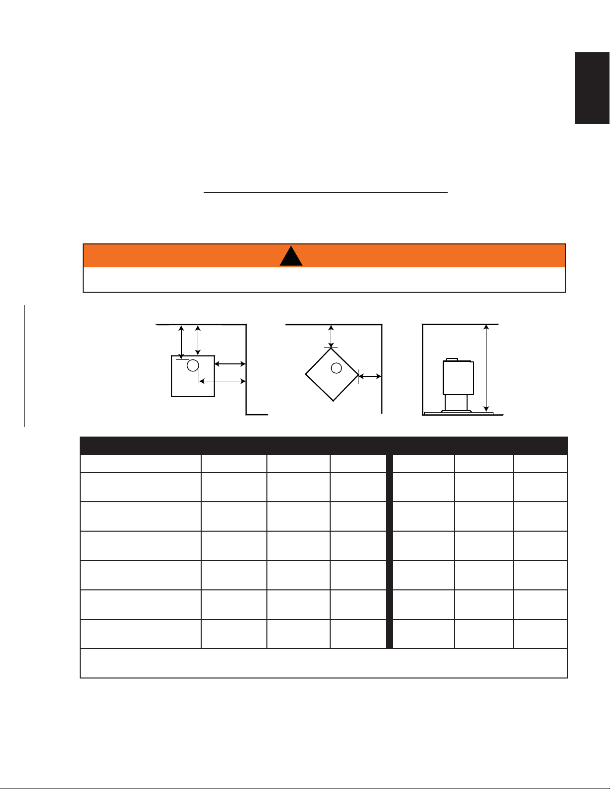
3.2 CLEARANCE TO COMBUSTIBLES
PARALLEL & CORNER SINGLE WALL CONNECTOR DOUBLE WALL CONNECTOR
S1 S4 S9 S1 S4 S9
SIDEWALL (A) 16”
(40.6cm)
16”
(40.6cm)
22”
(55.9cm)
16”
(40.6cm)
16”
(40.6cm)
22”
(55.9cm)
SIDEWALL TO FLUE (B) 21”
(53.3cm)
21”
(53.3cm)
21”
(53.3cm)
19”
(48.3cm)
19”
(48.3cm)
19”
(48.3cm)
BACKWALL (C) 10”
(254mm)
12”
(305mm)
12”
(305mm)
6”
(152mm)
6”
(152mm)
12”
(305mm)
BACKWALL TO FLUE (D) 13”
(33cm)
16.5”
(41.9cm)
16.5”
(41.9cm)
9”
(229mm)
9”
(229mm)
16.5”
(41.9cm)
CORNER (E) 6”
(152mm)
6”
(152mm)
8”
(203mm)
2”
(51mm)
4”
(102mm)
8”
(203mm)
CEILING (F) 7 feet
(2.1m)
7 feet
(2.1m)
7 feet
(2.1m)
7 feet
(2.1m)
7 feet
(2.1m)
7 feet
(2.1m)
Clearances can be reduced with shielding acceptable to local authorities. Reduced installation must comply
with NFPA 211 or CAN/CSA-B365.
BACK WALL
B
SIDE WALL
A
BACK WALL
C
SIDE WALL
F
D
E
E
W415-1476 / A / 09.30.16
10
EN
If possible connect the air intake at the pedestal’s back to outside air with a 4 inch (100mm) diameter fresh
air kit available at your authorized dealer / distributor. Follow detailed instructions under “Mobile Home
Outside Air”.
The following are signs that a fresh air kit may be required:
• When there is combustion present: Wood burns poorly, smoke spills, back-draft takes place and your
chimney does not draw steadily.
• In the winter there is too much condensation on the windows.
• Opening a window seems to alleviate the above symptoms.
• A ventilation system is installed in the house.
• Other devices are present that exhaust house air.
• The house has tight fi tting windows and/or is equipped with a well-sealed vapour barrier.
!
WARNING
IF ROOM AIR STARVATION OCCURS BECAUSE THE FRESH AIR INTAKE IS BLOCKED WITH ICE,
LEAVES, ETC., OR BECAUSE THE APPLIANCE DOOR WAS LEFT OPEN, OR DUE TO A STRONG
EXHAUST FAN OPERATING ETC., DANGEROUS FUMES AND SMOKE FROM THE OPERATING
APPLIANCE COULD BE DRAWN INTO THE ROOM.
99.1B
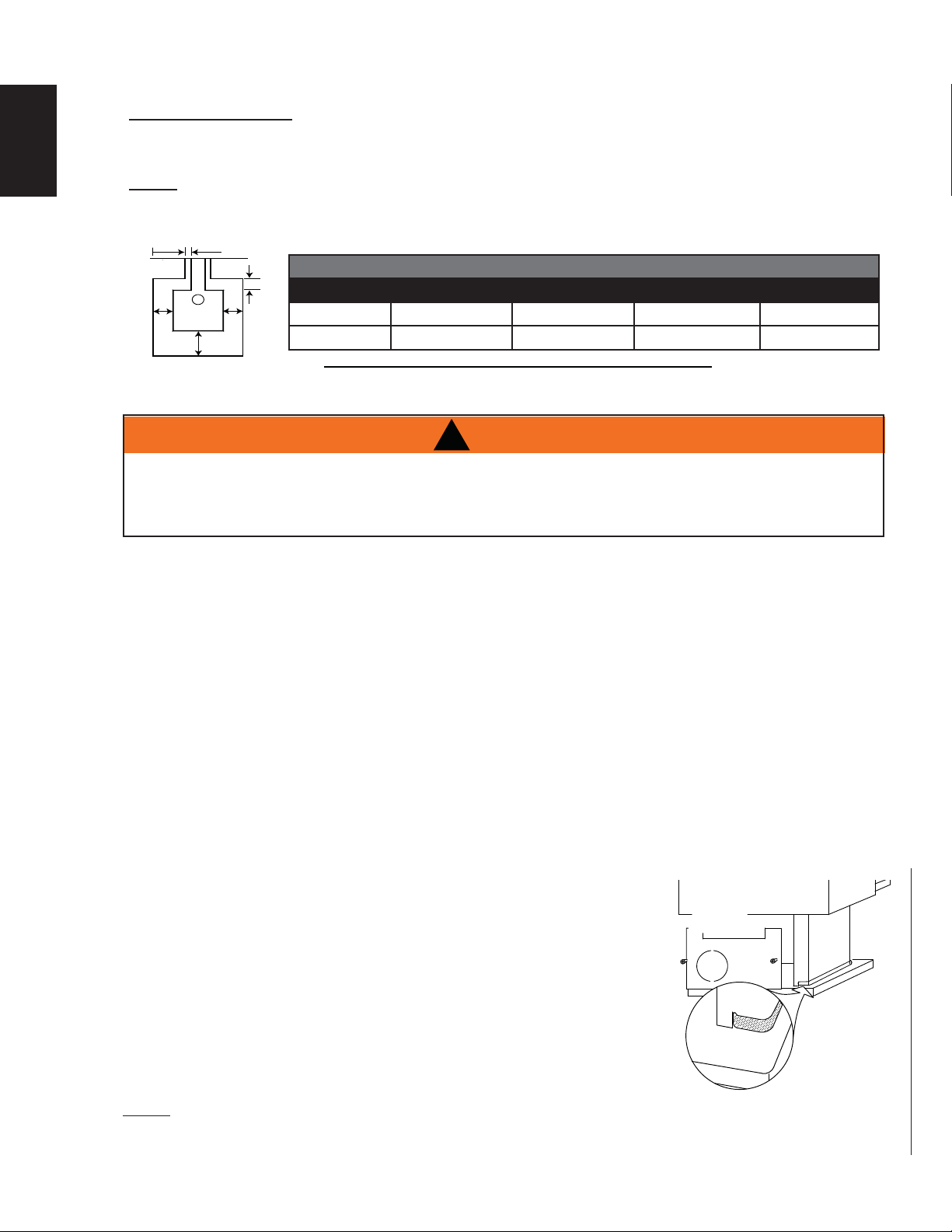
EMBER PROTECTOR:
This appliance must be installed on a non-combustible protector that extends to the front, sides and back of the
appliance as per the minimum requirements below.
NOTE: Ember protection is required for spark and ash shielding, not for limiting fl oor temperatures
from the radiant heat of the appliance. The appliance was designed and safety tested so that without
any protection, the fl oor will not overheat.
J
J
I
L
K
MINIMUM FLOOR PROTECTION
FRONT (I) SIDES (J) BACK (K) VENT (L)
CANADA 18” (45.7cm) 8” (203.2mm) 8” (203.2mm) N/A
USA 16” (40.6cm) 8” (203.2mm) 8” (203.2mm) 2” (50.8mm)
3.3 FLOOR PROTECTION
3.4 OUTSIDE AIR
Connection from the stove’s air intake to outside air is mandatory in mobile
homes only, either through a hole in the wall to line up with the knockout in the
pedestal back, or through a hole in the fl oor to line up with the hole in the
pedestal base. Use a fresh air kit. Secure the 4 inch diameter aluminum liner
by fl aring the end once it is inserted through the 4-1/2 inch diameter hole in
either the back or base of the pedestal. If the air intake is through the fl oor,
the hole in the pedestal back must be covered with sheet metal to avoid cold
air spillage into the room. A cover plate is available from your local authorized
dealer/distributor. Avoid cutting away fl oor joists, wall studs, electrical wires
or plumbing. Seal around the outside pipe with insulation to prevent drafts.
Attach the rear knockout plate (located inside the ash pan for shipping purposes).
NOTE: The S4 can only have outside air connected to pedestal backplate. Connection to bottom of
pedestal not available.
TRIM
PEDESTAL
KNOCKOUT
PLATE
3.4.1 OUTSIDE AIR - MOBILE HOME

W415-1476 / A / 09.30.16
11
EN
68.3C
!
WARNING
WEAR GLOVES AND SAFETY GLASSES FOR PROTECTION.
CAREFULLY FOLLOW THE INSTRUCTIONS FOR ASSEMBLY OF THE PIPE AND OTHER PARTS
NEEDED TO INSTALL THE APPLIANCE. FAILURE TO DO SO MAY RESULT IN A FIRE, ESPECIALLY IF
COMBUSTIBLES ARE TOO CLOSE TO THE APPLIANCE OR CHIMNEY AND AIR SPACES ARE
BLOCKED, PREVENTING THE FREE MOVEMENT OF COOLING AIR.
DO NOT DRAW OUTSIDE AIR FROM GARAGE SPACES. EXHAUST PRODUCTS OF GASOLINE ENGINES
ARE HAZARDOUS. DO NOT INSTALL OUTSIDE AIR DUCTS SUCH THAT THE AIR MAY BE DRAWN
FROM ATTIC SPACES, BASEMENTS OR ABOVE THE ROOFING WHERE OTHER HEATING APPLIANCES
OR FANS AND CHIMNEYS EXHAUST OR UTILIZE AIR. THESE PRECAUTIONS WILL REDUCE THE
POSSIBILITY OF APPLIANCE SMOKING OR AIR FLOW REVERSAL. THE OUTSIDE AIR INLET MUST
REMAIN CLEAR OF LEAVES, DEBRIS ICE AND/OR SNOW. IT MUST BE UNRESTRICTED WHILE
APPLIANCE IS IN USE TO PREVENT ROOM AIR STARVATION WHICH CAN CAUSE SMOKE SPILLAGE
AND AN INABILITY TO MAINTAIN A FIRE. SMOKE SPILLAGE CAN ALSO SET OFF SMOKE ALARMS.
NEGATIVE PRESSURE WITHIN YOUR HOME MAY INADVERTENTLY AFFECT YOUR APPLIANCE.
TO PREVENT CONTACT WITH SAGGING OR LOOSE INSULATION, THE APPLIANCE MUST NOT BE
INSTALLED AGAINST VAPOUR BARRIERS OR EXPOSED INSULATION. LOCALIZED OVERHEATING
COULD OCCUR AND A FIRE COULD RESULT.
DO NOT USE MAKESHIFT COMPROMISES DURING INSTALLATION. DO NOT BLOCK OR RESTRICT
AIR, GRILLE OR LOUVRE OPENINGS. DO NOT ADD A HOOD.
TO PREVENT PERSONAL INJURY KEEP HAND TOOLS IN GOOD CONDITION, SHARPEN CUTTING
EDGES AND MAKE SURE TOOL HANDLES ARE SECURE.
ALWAYS MAINTAIN THE MINIMUM AIR SPACE REQUIRED TO THE ENCLOSURE TO PREVENT FIRES.
!
WARNING
DO NOT INSTALL IN SLEEPING ROOM.
THE STRUCTURAL INTEGRITY OF THE MOBILE HOME FLOOR, WALL AND CEILING/ROOF MUST BE
MAINTAINED.
THE APPLIANCE MUST BE PROVIDED WITH OUTSIDE COMBUSTION AIR.
THE APPLIANCE MUST BE BOLTED TO THE FLOOR.
INSTALL ACCORDING TO 24 CFR, PART 3280 (HUD).
USE A CHIMNEY CERTIFIED FOR WOOD BURNING UL 103 S629, TYPE HT (2100°F).
MODEL S1 IS APPROVED FOR INSTALLATION IN MOBILE HOMES IN THE UNITED STATES & CANADA.
MODEL S4 IS APPROVED FOR INSTALLATION IN MOBILE HOMES IN THE UNITED STATES ONLY.
MODEL S9 IS NOT APPROVED FOR INSTALLATION FOR MOBILE HOMES IN THE UNITED STATES OR
CANADA.
NOTE: All mobile home approved appliances must be secured to the fl oor of the mobile home.
3.4.2 MOBILE HOME
4.0 INSTALLATION

W415-1476 / A / 09.30.16
12
EN
!
WARNING
NEVER INSTALL A SINGLE WALL SLIP SECTION OR SMOKE PIPE IN A CHASE STRUCTURE.
THE HIGHER TEMPERATURE OF THIS SINGLE WALL PIPE MAY RADIATE SUFFICIENT HEAT TO
COMBUSTIBLE CHASE MATERIALS TO CAUSE FIRE.
DO NOT CONNECT THIS APPLIANCE TO A CHIMNEY SYSTEM SERVING ANOTHER APPLIANCE.
TO AVOID DANGER OF FIRE, ALL INSTRUCTIONS MUST BE STRICTLY FOLLOWED, INCLUDING
THE PROVISIONS OF AIR SPACE CLEARANCE BETWEEN CHIMNEY SYSTEM AND ENCLOSURE.
TO PROTECT AGAINST THE EFFECTS OF CORROSION ON THOSE PARTS EXPOSED TO THE
WEATHER, WE RECOMMEND THAT THE CHASE TOP BE PAINTED WITH A RUST RESISTANT PAINT.
DO NOT FILL ANY FRAMED SPACE AROUND THE CHIMNEY WITH INSULATION OR ANY OTHER
MATERIAL. INSULATION PLACED IN THIS AREA COULD CAUSE ADJACENT COMBUSTIBLES TO
OVERHEAT.
MAINTAIN A MINIMUM 2” (50.8mm) AIR CLEARANCE TO ALL PARTS OF THE CHIMNEY SYSTEM AT
ALL TIMES (EXCLUDING THE CHIMNEY CONNECTOR). FAILURE TO MAINTAIN THIS 2” (50.8mm) AIR
CLEARANCE WILL CAUSE A STRUCTURE FIRE. NEVER FILL THIS SPACE WITH ANY TYPE OF MATERIAL.
DETAILED INSTRUCTIONS FOR INSTALLATION OF THE CHASE TOP, STORM COLLAR AND
TERMINATION CAP ARE PACKAGED WITH THESE PARTS. MINIMUM CLEARANCE TO
COMBUSTIBLES WILL VARY DEPENDING ON THEIR DESIGN.
DO NOT CUT RAFTERS OR CEILING JOISTS WITHOUT FIRST CONSULTING A BUILDING OFFICIAL
TO ENSURE STRUCTURAL INTEGRITY IS NOT COMPROMISED.
FIRESTOP SPACERS MUST BE USED WHENEVER THE CHIMNEY PENETRATES A CEILING/FLOOR AREA.
THE TOTAL HORIZONTAL VENT LENGTH SHOULD NOT EXCEED 40% OF THE CHIMNEY HEIGHT
ABOVE THE APPLIANCE. ALL HORIZONTAL SMOKE PIPE MUST SLOPE SLIGHTLY UPWARDS A
MINIMUM OF 1/4” (21.2mm) PER FOOT (METER) AND ALL CONNECTIONS MUST BE TIGHT AND
SECURED BY THREE SHEET METAL SCREWS EQUALLY SPACED. AN UNINSULATED SMOKE PIPE
SHALL NOT PASS THROUGH AN ATTIC, ROOF SPACE, CLOSET, OR SIMILAR CONCEALED SPACE,
OR THROUGH A FLOOR, CEILING, WALL OR PARTITION, OR ANY COMBUSTIBLE CONSTRUCTION.
DO NOT USE ANY MAKESHIFT MATERIALS DURING INSTALLATION.
63.8A
4.1 CHIMNEY
Your appliance may be connected to a factory built or masonry chimney. If you are using a factory built
chimney, it must comply with ULCS629 (Canada) or UL103 HT (USA) standards. It must therefore be a 6"
(152mm) HT Type (2100°F/1149°C) chimney. Use only specifi ed components with no substitutions. It is
extremely important that it be installed according to the manufacturer's specifi cations. The manufacturer's
installation instructions and specifi ed clearances should always be followed in accordance with local and
national codes. In Canada the CSA B365 and the CSA C22.1 installation codes are to be followed. In the USA
the ANSI NFPA 70 and ANSI NFPA 211 installation codes are to be followed.
Chimney and chimney connector must be in good condition and kept clean.
W415-1476 / A / 09.30.16
13
EN
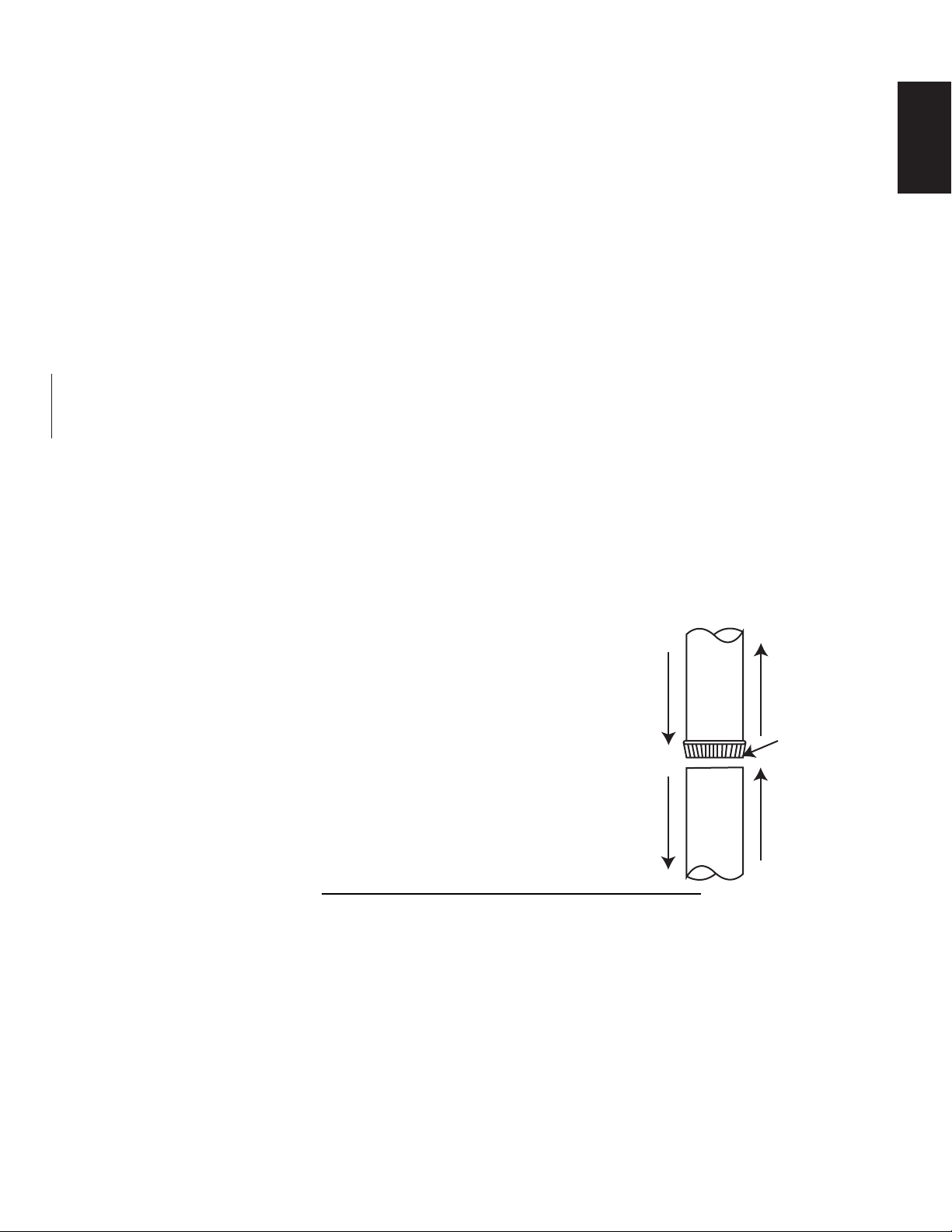
Your chimney connector and chimney must have the same diameter as the appliance’s exhaust fl ue outlet.
The appliance pipe must be made of aluminized or cold roll steel with a minimum 24 gauge (0.6mm)
thickness. It is strictly forbidden to use galvanized steel.
A 6” (152.4mm) diameter single wall chimney connector, used to connect the appliance to the chimney, must be
installed with the crimped end toward the appliance. This will ensure that the moisture which condenses from the
burning wood will fl ow back into the fi re chamber. Each joint in the chimney connector must be secured with at
least three sheet metal screws.
For installation of your chimney connector, the following recommendations may be useful.
• The chimney connector must be short and straight. For optimum performance it is recommended
that all horizontal runs have a minimum 1/4” (6.4mm) rise per foot (0.9m), with the upper end of the
section toward the chimney. For safe and proper operation of the appliance, see “INSTALLATION”
instructions.
• To insure a good draft, the total horizontal vent length should not exceed 40% of the chimney height
above the appliance. All horizontal smoke pipe must slope slightly upwards a minimum of 1/4”
(6.4mm) per foot (meter) and all connections must be tight. In the case of vertical installation, the total
length of the connector can be longer and connected without problem to the chimney at the ceiling
level.
• There should never be more than two 90° elbows in the entire connector and chimney system. Never
start with a 90° elbow. Always go up vertically for at least 2 feet (0.6m) from the fl ue collar before
using a 90° elbow.
• The connector must not pass through any combustible material, nor may it pass through a concealed
space (such as an attic, roof space, or closet). If passing through a wall, ceiling, or into a masonry
chimney, use either chimney components listed for that specifi c use, or means acceptable to local
authorities having jurisdiction over the installation.
4.1.1 CHIMNEY CONNECTION
This appliance must be connected to:
A. A chimney complying with the requirements for
Type HT chimneys in the Standard for Chimneys,
Factory-Built, Residential Type and Building Heating
Appliance, or
B. A code-approved masonry chimney with a fl ue
liner. Vent the stove into a masonry chimney or an
approved, insulated solid-fuel stainless-steel chimney
with as short and straight a length of 6” (152.4mm)
diameter chimney connector as possible. Connection
to a masonry chimney must be by a metal or masonry
thimble cemented in place.
TOWARD
APPLIANCE
FLUE GAS
DIRECTION
MALE END OF
CONNECTOR
OR CHIMNEY
PIPE
58.1B
W415-1476 / A / 09.30.16
14
EN
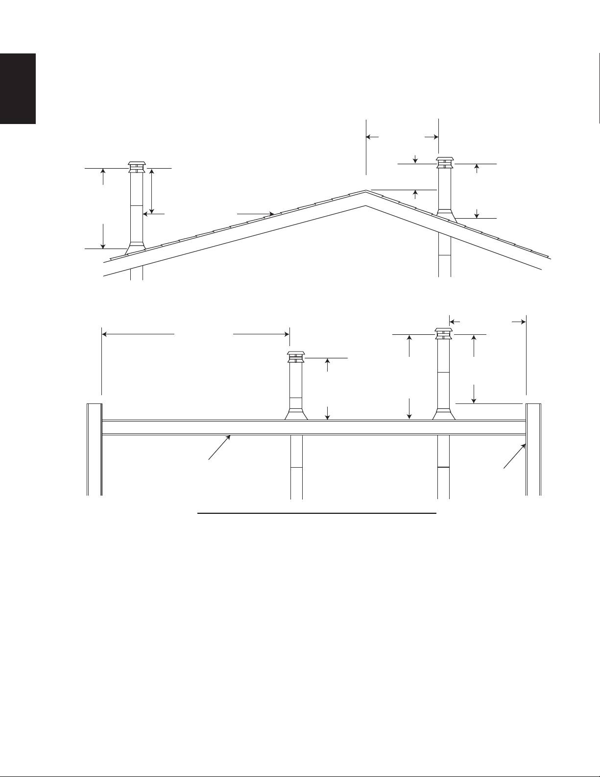
4.1.2 SECTIONS
A
dd chimney sections, according to the manufacturers installation instructions. The chimney must extend at
least, 3 feet (1m) above its point of contact with the roof and at least 24 inches (61cm) higher than any wall,
roof, building or obstacle within 10 feet (3m) horizontally.
59.1B
3 FT
(1m)
MIN
3 FT (1m)
MIN
10 FT (3m)
OR MORE
FLAT ROOF
WALL
10 FT (3m)
TO NEAREST
ROOFLINE
RIDGE
LESS THAN
10 FEET
(3m)
24” (61cm) MIN
3 FT (1m)
MIN
24” (61cm)
MIN
LESS THAN
10 FEET
(3m)
3 FT (1m)
MIN
24” (61cm)
MIN
W415-1476 / A / 09.30.16
15
EN
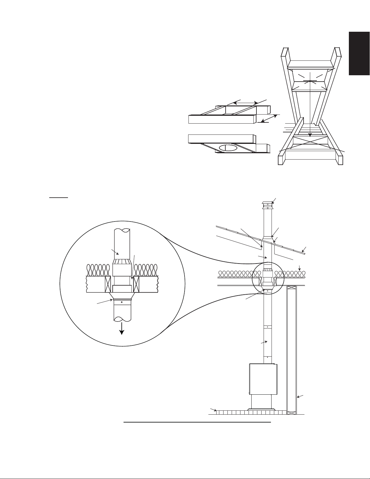
4.1.3 TYPICAL THROUGH THE CEILING
A. Move the stove into position with the fl ue centered, midpoint between two
joists to prevent having to cut them. Use a plumb bob to line up the center.
B. Cut and frame an opening in the ceiling to provide a 2” (50.8mm) clearance
between the outside of the chimney and any combustible material. DO NOT
FILL THIS SPACE WITH ANY TYPE OF MATERIAL.
Nail headers between the joist for extra support.
Firestop spacers must be placed on the
bottom of each framed opening in any fl oor
or ceiling that the chimney passes through.
If your chimney system is enclosed within
the attic area, a rafter radiation shield is
required.
C. Hold a plumb bob from the underside of
the roof to determine where the opening in
the roof should be. Cut and frame the roof
opening to maintain proper 2” (50.8mm) clearances.
NOTE: The chimney must be supported at the ceiling or roof so that it’s
weight does not rest on the appliance and must comply with it’s
manufacturer’s instructions.
60.1B
HEADERS
FIRESTOP SPACER -
UNDERSIDE OF JOIST
FLOOR
PROTECTOR
ROOF
FLASHING
STORM
COLLAR
TERMINAL
COMBUSTIBLE
WALL
MAINTAIN
2” (50.8mm)
CLEARANCE
CHIMNEY
CONNECTOR
CHIMNEY
SUPPORT
LISTED CHIMNEY
INSULATION
CEILING
SUPPORT
LISTED
CHIMNEY
SPECIFIED
CLEARANCE
TO STOVE
W415-1476 / A / 09.30.16
16
EN
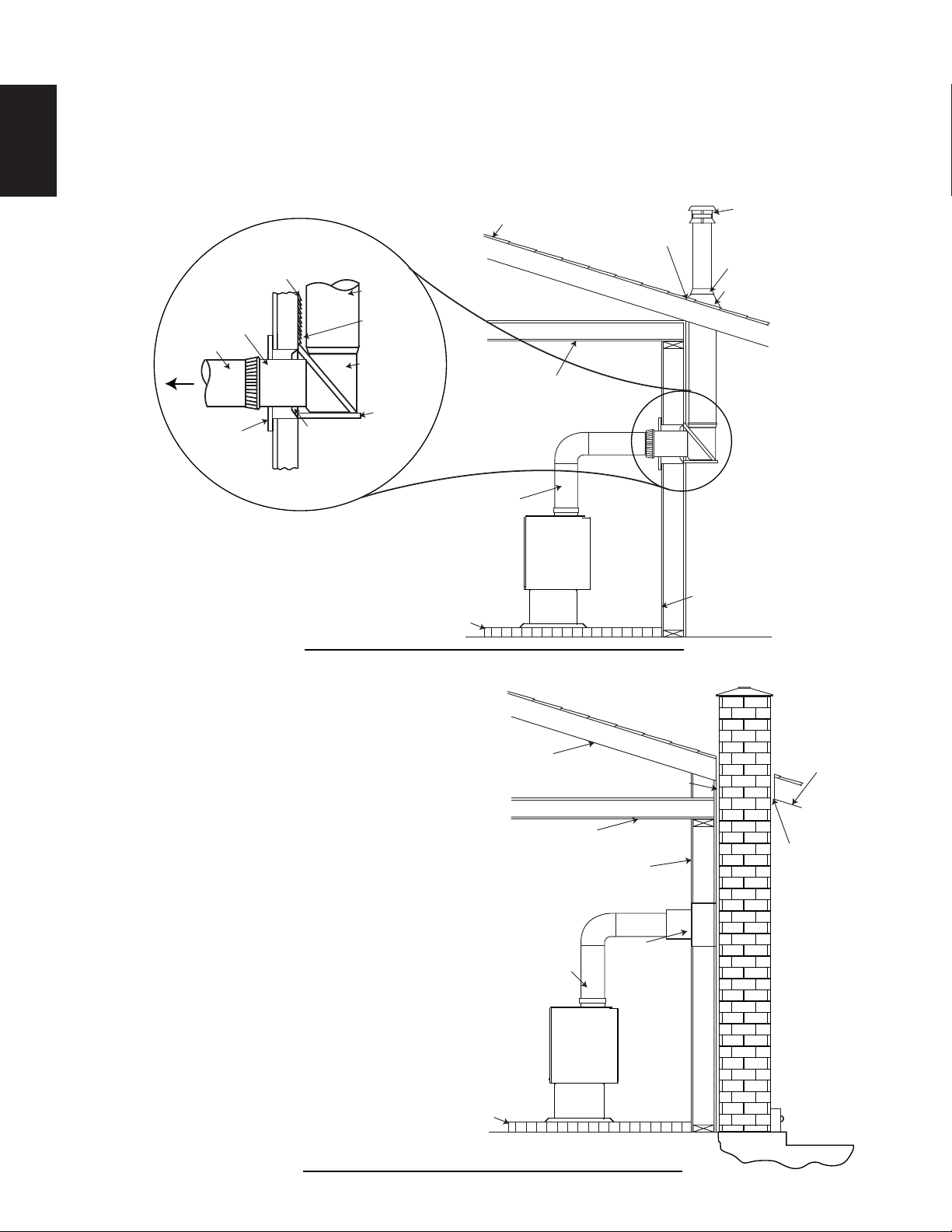
4.1.4 TYPICAL THROUGH THE WALL
If possible, design the installation so that the connector does not pass through a combustible wall. If during
your installation you must pass through a combustible wall, check with your building inspector before you
begin. Also check with the chimney connector manufacturer for any specifi c requirements.
Consult with your dealer regarding special connection components available for use for wall pass-throughs.
Use only parts that have been tested and listed for use in a wall pass-through.
61.1A
FLOOR
PROTECTOR
ROOF
FLASHING
STORM
COLLAR
TERMINAL
COMBUSTIBLE
WALL
MAINTAIN 2”
(50.8mm) CLEARANCE
THROUGH EAVE
COMBUSTIBLE
CEILING
LISTED
CHIMNEY
COMBUSTIBLE
OUTSIDE WALL
TO
STOVE
2” (50.8mm)
CLEARANCE
INSULATED
“T”
WALL
SUPPORT
WALL SPACER
FOR OUTSIDE
WALL
SECTION
LISTED
CHIMNEY
PIPE
THIMBLE
CHIMNEY
CONNECTOR
4.1.5 TYPICAL EXISTING MASONRY
You can also install your appliance using your existing
masonry chimney. To do so, follow the guidelines
below. Use a factory-built thimble, or construct
your own brick thimble. If you are using a masonry
chimney, it is important that it be built in compliance
with the specifi cations of the Building Code in
your region. It must normally be lined with fi re clay
bricks, metal or clay tiles sealed together with fi re
cement. (Round fl ues are the most effi cient). The
maximum fl ue size is 8” (203.2mm) x 8” (203.2mm)
square or 6” (152.4mm) round. For greater diameters
it is necessary to install a 6” stainless steel liner.
62.1A
FLOOR
PROTECTOR
CHIMNEY
CONNECTOR
COMBUSTIBLE
WALL
CLEARANCE
EAVE
RAFTER
CLEARANCE WITH FIRESTOP
CEILING JOIST
THIMBLE
W415-1476 / A / 09.30.16
17
EN
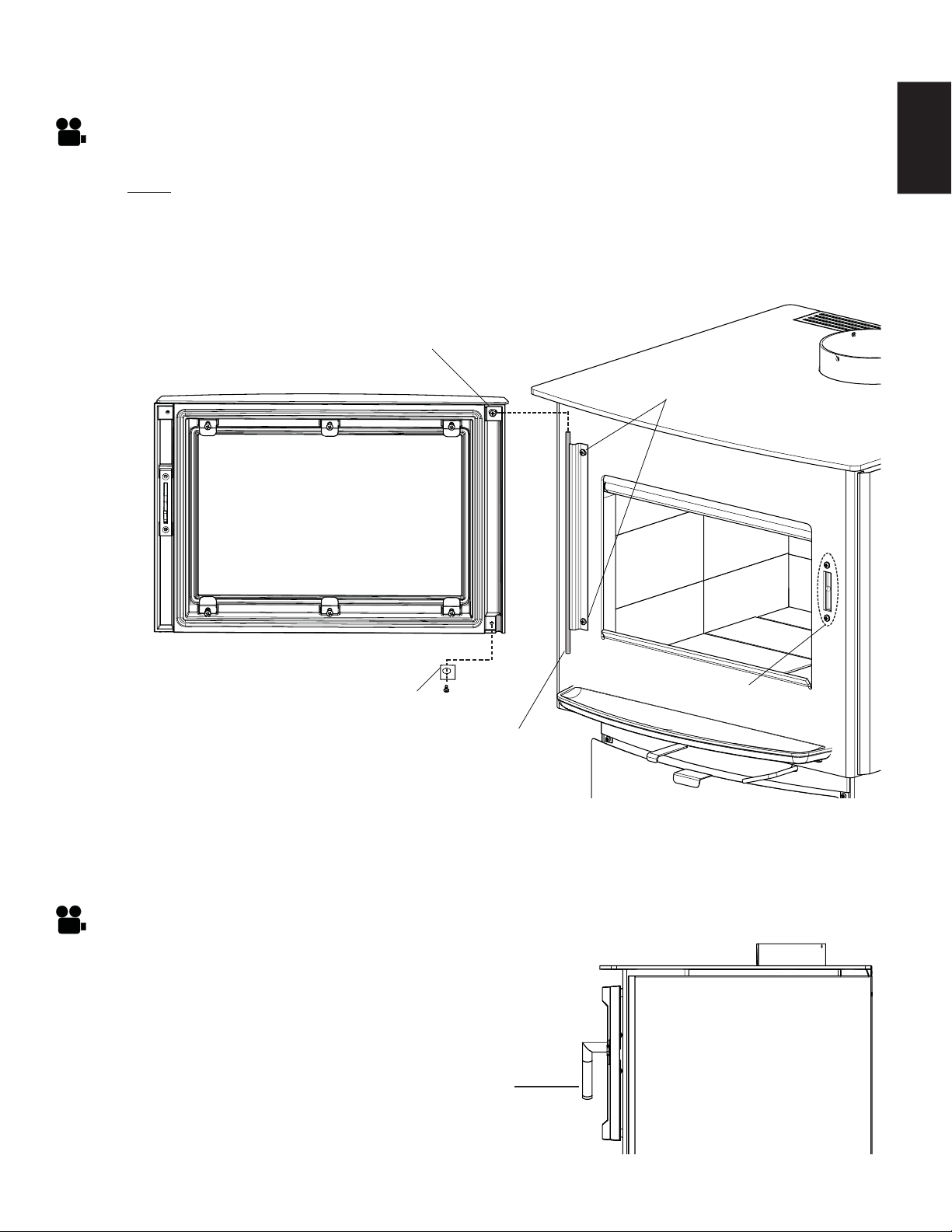
5.0 FINISHING
A. Remove the bottom door hinge retainer by removing the screw, as shown below, then loosen the
top door hinge retainer.
B. Lift the door up and off of the hinge rod.
C. Carefully place the door facedown, on a soft surface, to avoid scratching the paint.
D. Install the door in reverse order.
5.1 DOOR REMOVAL / INSTALLATION
HINGE ROD
DOOR HINGE RETAINER
DOOR HINGE RETAINER
HINGE SCREWS
LATCH BLOCK
HOUSING
Ensure to have a fi rm grip of the door at all times.
NOTE: We recommend having two people perform this installation.
A. Loosen the two hinge screws to adjust the horizontal (levelling) position of the door.
B. Tighten the two hinge screws after the desired door position has been reached.
A. Loosen the two screws of the latch block housing.
B. Shift the latch block housing up or down to suit the desired
handle pitch. (HINT: Shifting the latch block housing up
will result in a lower handle pitch. Shifting the latch block
housing down will result in a higher handle pitch.)
PITCH OF HANDLE IN
CLOSED POSITION
5.1.1 DOOR ADJUSTMENT
5.1.2 LATCH BLOCK HOUSING ADJUSTMENT
W415-1476 / A / 09.30.16
18
EN
!
WARNING
BURNING YOUR APPLIANCE WITH THE DOORS OPEN OR AJAR CREATES A FIRE HAZARD THAT
MAY RESULT IN A HOUSE AND OR CHIMNEY FIRE.
DO NOT STRIKE OR SLAM DOOR.
NEVER REMOVE THE DOOR WHEN THE APPLIANCE IS HOT.
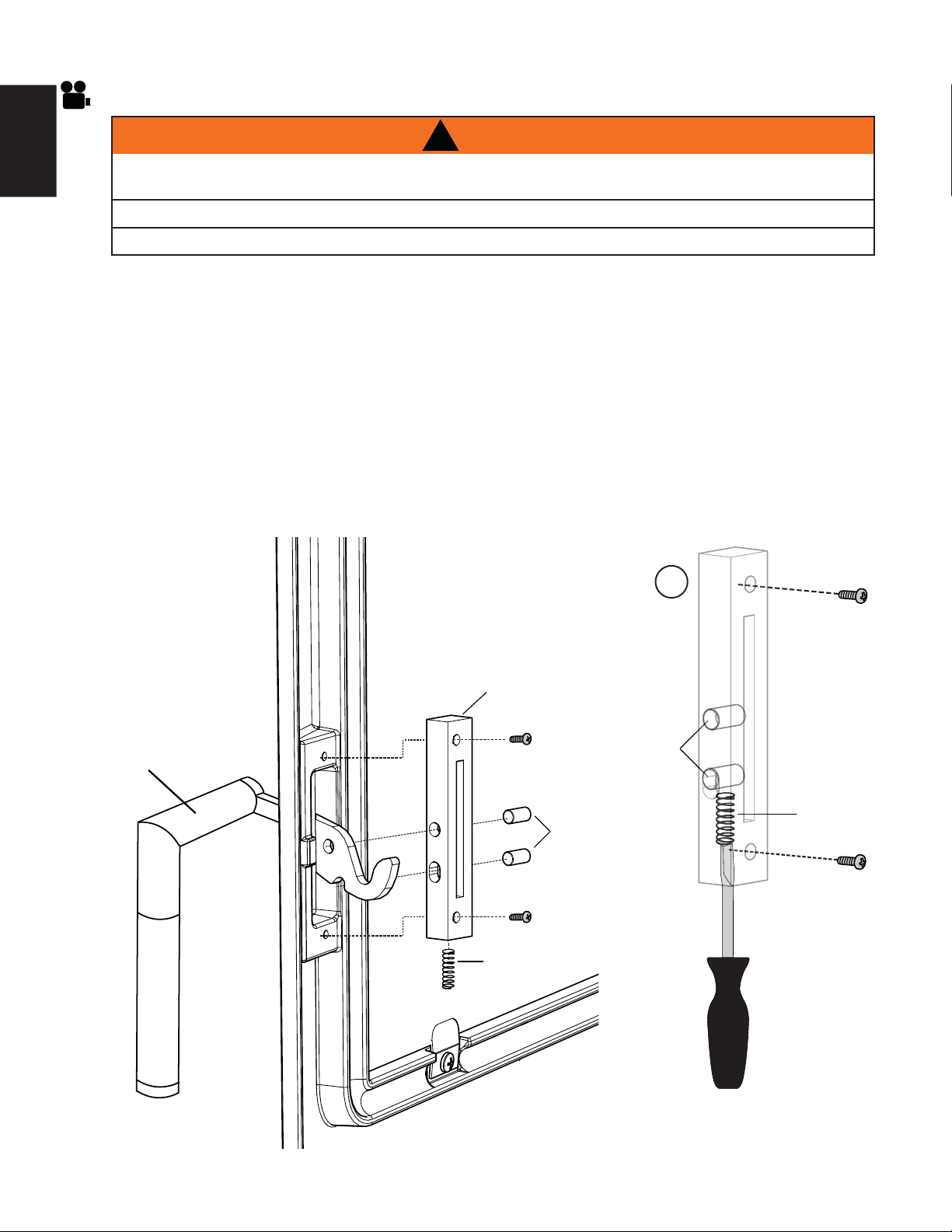
5.2 HANDLE AND DOOR SERVICE AND INSTALLATION
E
SPRING
PINS
SPRING
PINS
LATCH BLOCK
HANDLE
A. Remove the two screws securing the latch block to the door.
B. Pull the handle towards the inside of the door and remove the latch block components, then remove
the latch block and handle. Replace any damaged or worn components.
C. To reinstall the door handle take the latch block and door handle, align the top and bottom screw
holes to the door, as illustrated.
D. Loosely tighten the top screw and install the two pins, as illustrated.
E. Installing the spring, slip it into the bottom of the latch block and then install the screw. Apply a small
amount of high temperature grease to the spring, prior to installation. HINT: Compress the spring
using a fl at head screw driver, this allows for easy installation of the bottom screw, as shown
below.
F. To ensure a proper installation, the handle support should have the ability to remain in an upwards
position. Additionally, the handle support should engage smoothly with the fi rebox.
W415-1476 / A / 09.30.16
19
EN
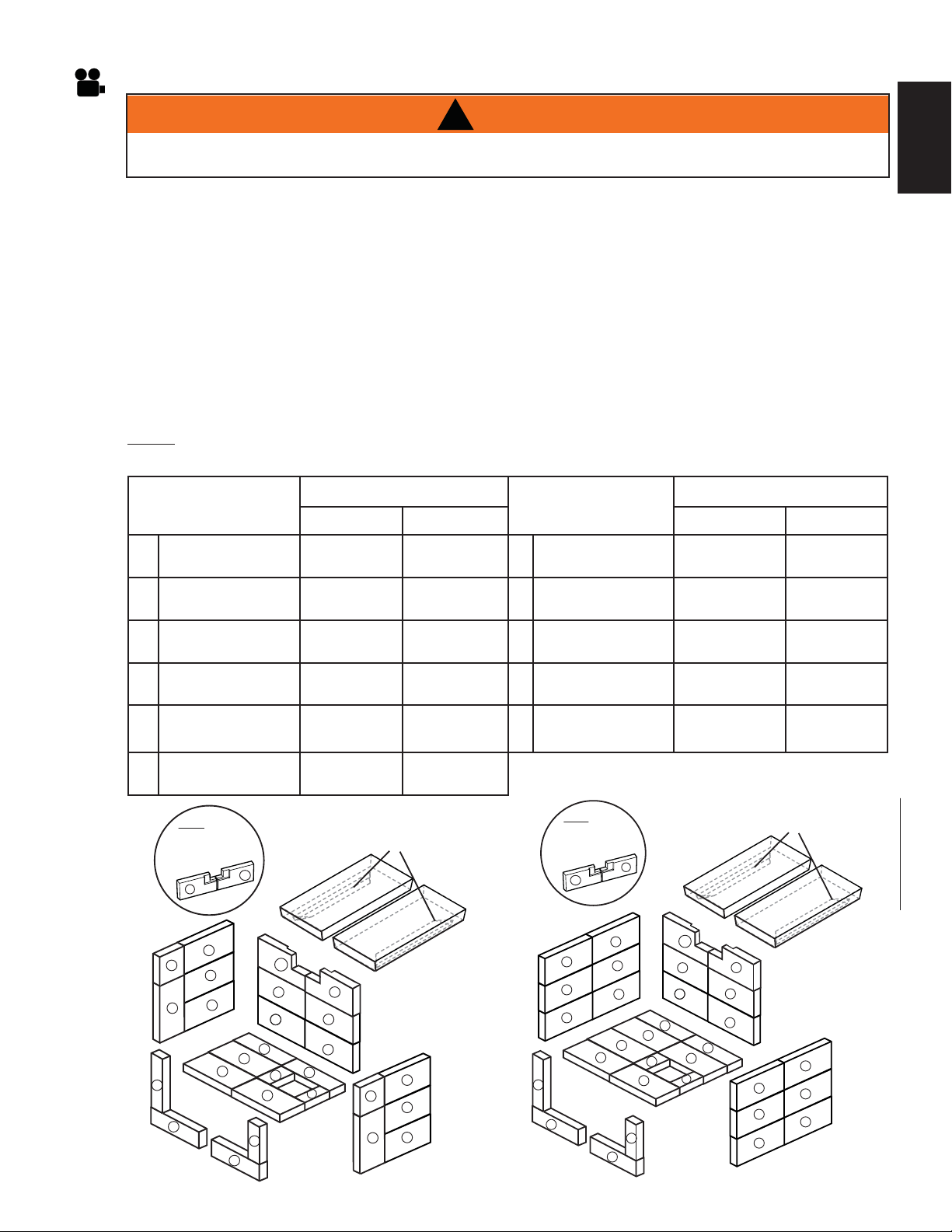
5.3 BRICKS AND BAFFLE INSTALLATION
!
WARNING
OPERATION OF THE APPLIANCE WITHOUT THE BAFFLES CAN RESULT IN EXCESSIVE TEMPERATURES
THAT COULD DAMAGE THE APPLIANCE, CHIMNEY AND THE SURROUNDING ENCLOSURE.
With appliance and chimney installation completed, move the bricks into place for your appliance as
illustrated.
A. Install the bottom bricks, working from the back of the appliance forward.
B. Before installing the back bricks, loosen the screw holding the brick retainer and ensure that it has
been moved forward. Install the six bricks along the back wall by pivoting the bricks up under the
brick retainer. Re-tighten the screw.
C. Install the fi rst two rows of side bricks as shown in the illustration below.
D. Pivot the fi bre baffl es into place with the brick retainer edge down and toward the outside of the
appliance. Slide the top row of bricks into place to support the baffl e. The baffl e must sit fl at on the
outside row of bricks as well as the fl ange on the manifold shield. Push the baffl e all the way to the
rear of the fi rebox, leaving a minimum of 1” (25mm) gap along the front. This will allow fl ue gases to
escape the fi rebox.
E. Install the remaining bricks along the front opening, as illustrated below.
NOTE: Do not operate without the bricks, baffl e and manifold shield are not in position.
All Firebricks are 1 1/4” (32mm) Thick
A
A
A
A
A
A
A
A
A
A
A
A
A
D
D
B
B
C
C
E
F
I
J
G
NOTE: BRICKS
E & F ARE
NOTCHED AT
REAR.
H
(Fibre Baffles)
W018-0077 X2
BRICK
RETAINERS
K
E
F
K
K
S1
D
D
A
A
A
A
A
A
A
A
A
A
A
A
A
B
B
E
F
I
J
G
F
NOTE: BRICKS
E & F ARE
NOTCHED AT
REAR.
H
(Fibre Baffles)
W018-0078 X2
BRICK
RETAINERS
A
A
A
A
A
A
E
K
K
K
S4
FIREBRICK
DIMENSIONS
PART #
FIREBRICK
DIMENSIONS
PART #
S1 S4 S1 S4
A
4 1/2” x 9”
(114mm x 229mm)
W090-0001
X12
W090-0001
X18
G
2 1/4” x 9”
(57mm x 229mm)
W090-0018
X1
W090-0018
X1
B
3” x 9” (Molded)
(6mm x 229mm)
W090-0002
X2
W090-0002
X2
H
1 3/4” x 4 3/4”
(64mm x 121mm)
W090-0216
X1
W090-0216
X1
C
4 1/2” x 4 1/2”
(114mm x 144mm)
W090-0003
X2
N/A
I
2 1/2” x 4 1/2”
(64mm x 114mm)
W090-0016
X1
W090-0016
X1
D
3” x 9”
(76mm x 229mm)
W090-0166
X2
W090-0166
X2
J
1 1/2” x 4 1/2”
(38mm x 114mm)
W090-0017
X1
W090-0017
X1
E
4 1/2” x 9”(Notched)
(114mm x 229mm)
W090-0207
X1
W090-0207
X1
K
4 1/2” x 8 1/4”
(114mm x 216mm)
W090-0184
X3
W090-0184
X3
F
4 1/2” x 9”(Notched)
(114mm x 229mm)
W090-0208
X1
W090-0208
X1
W415-1476 / A / 09.30.16
20
EN
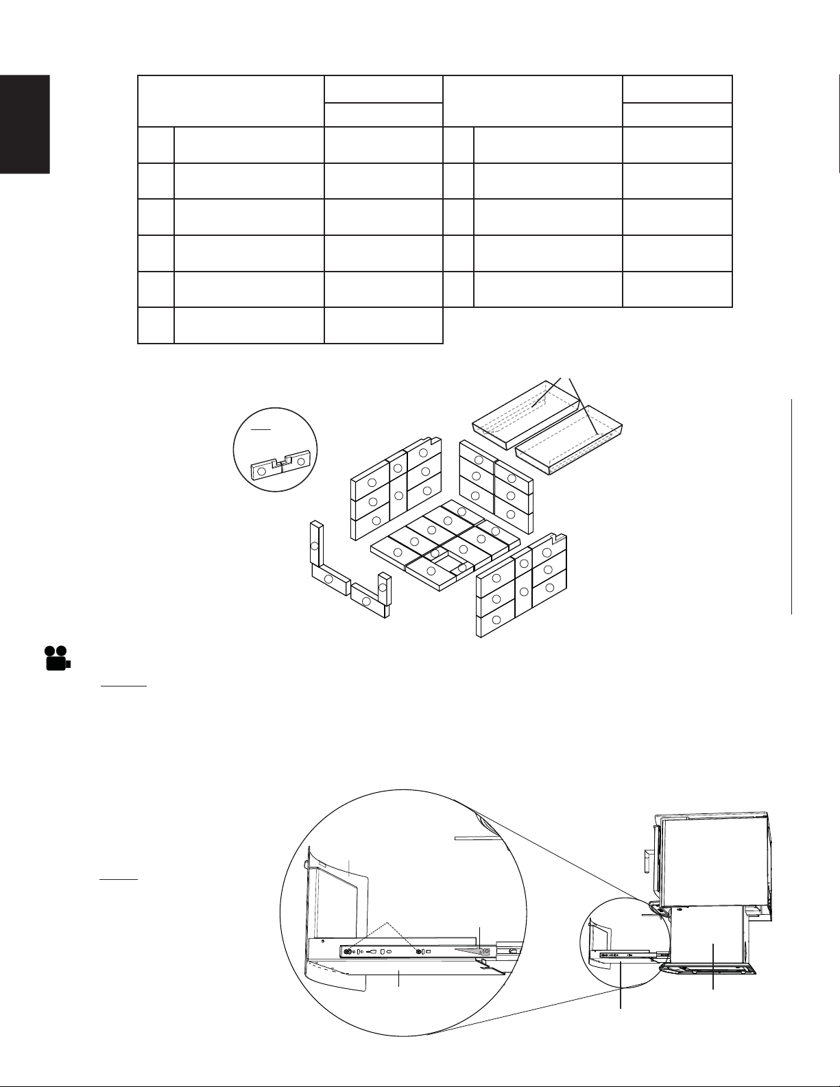
S9
5.4 ASH DRAWER ADJUSTMENT
NOTE: If ash drawer adjustment is necessary there are adjustment areas located on the sides and
bottom of the ash drawer, as illustrated below.
A. Remove the ash drawer from the appliance by pressing the drawer disconnect lever down on the
right side and upwards on the left side then pull the ash drawer out from the pedestal.
B. To change the spacing between the ash drawer cover and pedestal, loosen the side adjustment
screws (both sides) and position to the desired space, then tighten the screws.
SIDE
ADJUSTMENT
SLOTS/SCREWS
ASH
DRAWER
COVER
ASH
DRAWER
HOUSING
DRAWER
DISCONNECT
LEVER
PEDESTAL
ASH DRAWER
NOTE: Always ensure the
ash pan is completely
cool prior to removing it
from the ash drawer.
FIREBRICK
DIMENSIONS
PART #
FIREBRICK
DIMENSIONS
PART #
S9 S9
A
4 1/2” x 9”
(114mm x 229mm)
W090-0015
X20
G
2 1/4” x 9”
(57mm x 229mm)
W090-0018
X1
B
3” x 9” (Molded)
(6mm x 229mm)
W090-0002
X2
H
1 3/4” x 4 3/4”
(64mm x 121mm)
W090-0216
X1
C
4 1/2” x 4 1/2”
(114mm x 144mm)
W090-0003
X2
I
2 1/2” x 4 1/2”
(64mm x 114mm)
W090-0016
X1
D
3” x 9”
(76mm x 229mm)
W090-0166
X4
J
1 1/2” x 4 1/2”
(38mm x 114mm)
W090-0017
X1
E
4 1/2” x 9”(Notched)
(114mm x 229mm)
W090-0207
X1
K
4 1/2” x 8 1/4”
(114mm x 216mm)
W090-0184
X3
F
4 1/2” x 9”(Notched)
(114mm x 229mm)
W090-0208
X1
A
A
A
A
A
A
A
A
A
A
A
A
A
A
A
A
A
A
B
B
D
D
I
J
G
A
A
C
C
D
D
F
E
(Fibre Baffles)
W018-0130 X2
H
BRICK
RETAINERS
E
NOTE: BRICKS
E & F ARE
NOTCHED AT REAR.
F
K
K
K
W415-1476 / A / 09.30.16
21
EN
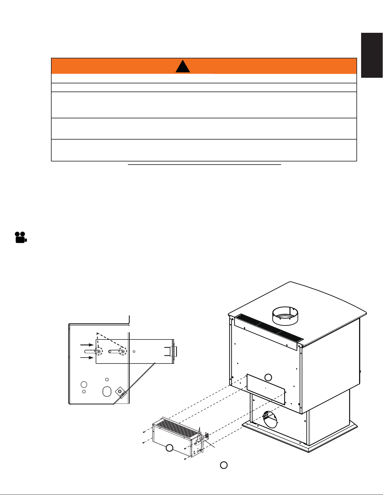
KNOCK-OUT
BLOWER
C
D
B
THERMAL DISC
BRACKET
SCREWS
Provisions have been made on the stove to install an optional blower kit (EP65) that comes complete with a
variable speed switch to turn the blower on and off, as well as adjusting the blower speed and a thermostatic
sensor to thermally activate the blower.
Drywall dust will penetrate into the blower bearings, causing irreparable damage. Care must be taken to
prevent drywall dust from coming into contact with the blower or its compartment. Any damage resulting from
this condition is not covered by the warranty policy.
Use of the blower increases the output of heat.
A. Ensure the thermal disc bracket is in the correct position, refer to Figure 1.
B. Remove the knock-out from the back of the appliance.
C. Install the blower and housing as shown using the 4 screws supplied, refer to Figure 2.
D. Loosen the thermal disc bracket (2 screws) and slide
the bracket until the thermal disc is touching the rear
of the fi rebox and secure.
Fig. 2
6.0 OPTIONAL KIT INSTALLATIONS
6.1 BLOWER KIT INSTALLATION
!
WARNING
RISK OF FIRE AND ELECTRICAL SHOCK.
TURN OFF THE GAS AND ELECTRICAL POWER BEFORE SERVICING THIS APPLIANCE.
USE ONLY WOLF STEEL APPROVED OPTIONAL ACCESSORIES AND REPLACEMENT PARTS WITH
THIS APPLIANCE. USING NON-LISTED ACCESSORIES (BLOWERS, DOORS, LOUVRES, TRIMS, GAS
COMPONENTS, VENTING COMPONENTS, ETC.) COULD RESULT IN A SAFETY HAZARD AND WILL
VOID THE WARRANTY AND CERTIFICATION.
ENSURE THAT THE FAN’S POWER CORD IS NOT IN CONTACT WITH ANY SURFACE OF THE
APPLIANCE TO PREVENT ELECTRICAL SHOCK OR FIRE DAMAGE. DO NOT RUN THE POWER
CORD BENEATH THE APPLIANCE.
THE WIRE HARNESS PROVIDED IN THE BLOWER KIT IS A UNIVERSAL HARNESS. WHEN
INSTALLED, ENSURE THAT ANY EXCESS WIRE IS CONTAINED, PREVENTING IT FROM MAKING
CONTACT WITH MOVING OR HOT OBJECTS.
51.5
TURN OFF THE ELECTRICAL POWER BEFORE SERVICING THIS APPLIANCE.
THERMAL DISC BRACKET
Fig. 1
6.1.1 BLOWER INSTALLATION
W415-1476 / A / 09.30.16
22
EN
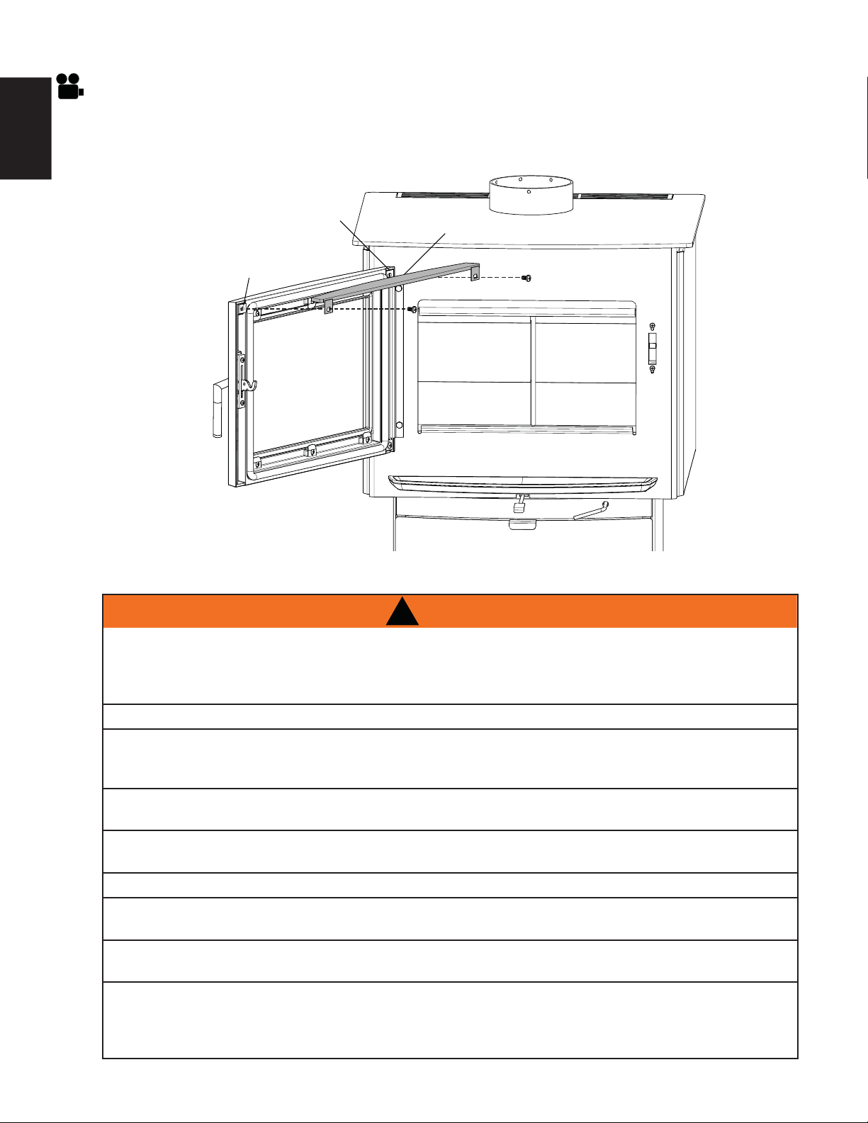
6.2 DOOR TRIM KIT
A. Open the door of the appliance.
B. Remove the right side screw, holding the top door hinge retainer in place.
C. Place one shim against the door, on the left side.
D. Set the trim on the top of the door, align to the holes, and secure.
TOP DOOR
HINGE RETAINER
DOOR TRIM
SHIM
!
WARNING
ALWAYS OPERATE THIS APPLIANCE WITH THE DOOR CLOSED AND LATCHED EXCEPT DURING
START UP AND RE-FUELING. ALWAYS WEAR GLOVES TO PREVENT INJURY. DO NOT LEAVE THE
FIRE UNATTENDED WHEN THE DOOR IS UNLATCHED AS UNSTABLE WOOD COULD FALL OUT OF
THE FIRE CHAMBER CREATING A FIRE HAZARD TO YOUR HOME.
NEVER LEAVE CHILDREN UNATTENDED WHEN THERE IS A FIRE BURNING IN THE APPLIANCE.
NEVER USE GASOLINE, GASOLINE-TYPE LANTERN FUEL, KEROSENE, CHARCOAL LIGHTER FLUID,
OR SIMILAR LIQUIDS TO START OR ‘FRESHEN UP’ A FIRE IN THIS APPLIANCE. KEEP ALL SUCH
LIQUIDS WELL AWAY FROM THE APPLIANCE WHILE IT IS IN USE.
OBJECTS PLACED IN FRONT OF THE APPLIANCE SHOULD BE KEPT A MINIMUM OF 4 feet
(1.2m) FROM THE FRONT FACE.
ANY MODIFICATION OF THE APPLIANCE THAT HAS NOT BEEN APPROVED IN WRITING BY THE
TESTING AUTHORITY IS CONSIDERED BREACHING CSA B365 (CANADA) AND ANSI NFPA 211 (USA).
OPEN AIR CONTROL (AND DAMPER WHEN FITTED) BEFORE OPENING FIRING DOOR.
HOT WHILE IN OPERATION, KEEP CHILDREN, CLOTHING AND FURNITURE AWAY. CONTACT MAY
CAUSE SKIN BURNS. WEAR GLOVES TO OPERATE YOUR APPLIANCE.
BURNING YOUR APPLIANCE WITH THE DOORS OPEN OR AJAR CREATES A FIRE HAZARD
THAT MAY RESULT IN A HOUSE AND OR CHIMNEY FIRE.
THIS WOOD APPLIANCE HAS A MANUFACTURER-SET MINIMUM LOW BURN RATE THAT MUST
NOT BE ALTERED. IT IS AGAINST FEDERAL REGULATIONS IN THE UNITED STATES TO ALTER THIS
SETTING OR OTHERWISE OPERATE THIS WOOD APPLIANCE IN A MANNER INCONSISTENT WITH
OPERATING INSTRUCTIONS IN THIS MANUAL.
7.0 OPERATION

W415-1476 / A / 09.30.16
23
EN
Your appliance is Hi-Tech, designed with the most advanced technology. This appliance is extremely airtight.
It has an exclusive direct outside air supply (optional kit), a feature designed to prevent spillage, and to
help keep your house free of carbon monoxide, in case of a down drafting chimney or an internal negative
pressure.
The fi rst fi re(s) in your appliance will be diffi cult to get going and keep going with little amount of heat being
generated. This is a result of the moisture being driven out of the fi re brick. During the break-in period (the
fi rst 2 or 3 fi res) create only small, fi res using kindling; this will allow the fi rebrick to cure. Do not be alarmed if
small hairline cracks develop in the fi rebrick. This is a normal occurrence and does not pose a safety hazard.
The paint may also smell a little for the fi rst few fi res as it cures and you may wish to open a door or window
to alleviate the smell.
To start, a brisk fi re is required. Place loosely crumpled paper on the fl oor of the appliance and cover with dry
kindling. Open the air control fully by pulling the lever forward. Light the paper and leave the door slightly ajar
(one inch/25.4mm) until all kindling is burning. To maintain a brisk fi re, a hot coal bed must be established and
maintained.
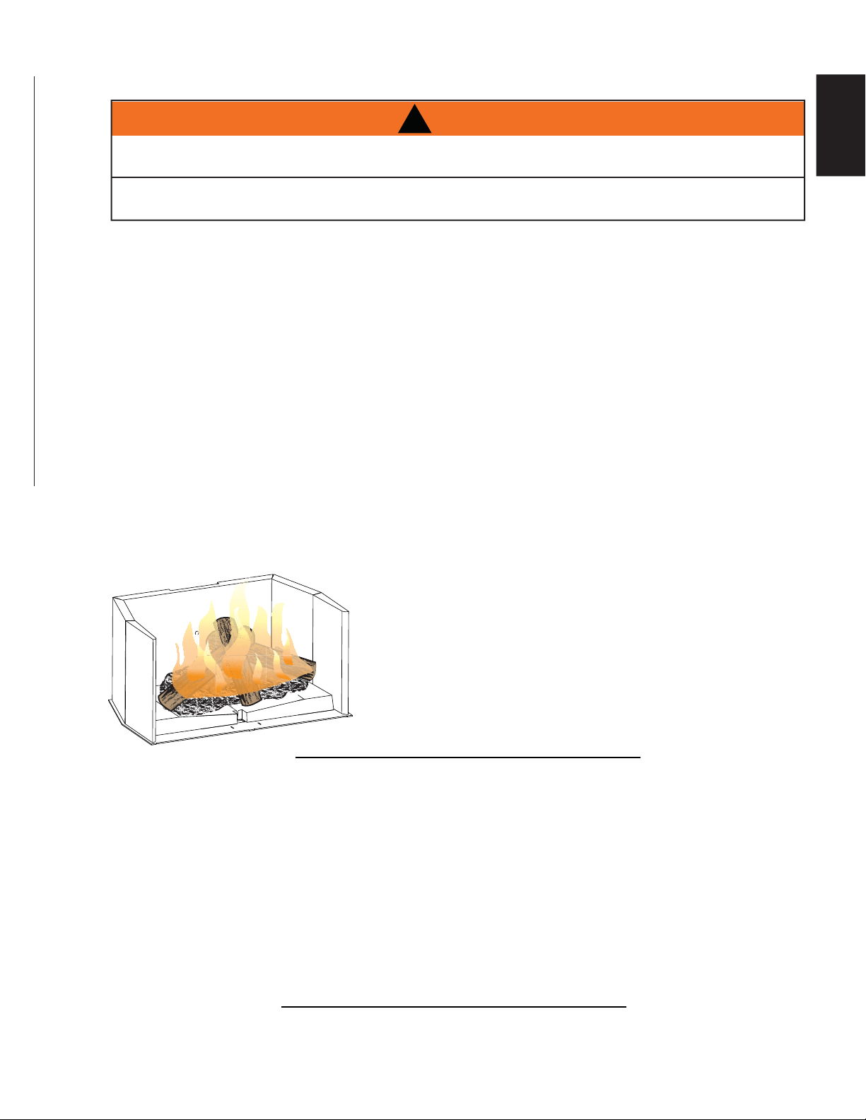
Slowly add larger wood (2” x 4” size pieces). Lay the pieces lengthwise from side to side in the hot coal
bed with a shallow trench between, so that the primary air can fl ow directly into this trench and ignite the
fuel above. When the fi re seems to be at its peak, medium sized logs may be added. Once these logs have
caught fi re, carefully close the door. (Closing the door too quickly after refuelling will reduce the fi rebox
temperature and result in an unsatisfactory burn.) Remember it is more effi cient to burn medium sized wood,
briskly, and refuel frequently than to load the appliance with large logs that result in a smouldering, ineffi cient
fi re and dirty glass.
As soon as the door is closed, you will observe a change in the fl ame pattern. The fl ames will get smaller and
lazier because less oxygen is getting into the combustion chamber. The fl ames, however, are more effi cient.
The fl ames will remain lazy but become larger again as soon as the fi rebricks have been heated thoroughly
and the chimney becomes heated and provides a good draft. At this point, the roaring fi re that you see when
the door is opened is wastefully drawing heated room air up the chimney -- certainly not desirable. Always
operate with the door fully closed once the medium sized logs have caught fi re.
You can now add larger pieces of wood and operate the appliance normally. Once the appliance is entirely
hot, it will burn very effi ciently with little smoke from the chimney. There will be a bed of orange coals in the
fi rebox and secondary fl ames fl ickering just below the top fi rebrick. You can safely fi ll the fi rebox with wood
to the top of the door and will get best burns if you keep the chimney connector temperatures between 250°F
(120°C) and 450°F (270°C).
Without an appliance thermometer, you are working blindly and have no idea of how the appliance is
operating! An appliance thermometer offers a guide to performance and should be located 18” (457mm)
above the fl ue collar into the chimney connector. Install the thermometer according to manufacturers
instructions.
Can’t get the fi re going?
Use more kindling and paper. Assuming the chimney and vent are sized correctly and there is suffi cient
combustion air, the lack of suffi ciently dry quantities of small kindling is the problem. Thumb size is a good
gauge for small kindling diameter.
Can’t get heat out of the appliance?
One of two things may have happened. The appliance door may have been closed prematurely and the
appliance itself has not reached optimum temperature. Reopen the door and/or draft control to re-establish
a brisk fi re. The other problem may have been wet wood. The typical symptom is sizzling wood and moisture
being driven from the wood.
W415-1476 / A / 09.30.16
24
EN
7.1 OPTIMUM BURN METHOD
For optimal emissions performance and effi ciency follow these simple guidelines when using your appliance:
A. Maintain a 2" (51mm) deep, hot, glowing red coal bed.
B. Burn dry seasoned wood with less than 20% moisture content and burn so that the glass door
remains clean.
C. A stove thermometer 18" (457mm) up on the single wall stove pipe should indicate 350°F (176°C) as
an average temperature.
D. Maintain a minimal trace of smoke coming from the chimney when the appliance is burning as
intended.
E. Inspect and replace all necessary components such as gaskets, manifolds, glass and other
components which may affect the overall appliance performance.
F. Ensure an adequate draft to control burn rate and temperature.
Refer to “OPERATION” and “MAINTENANCE” sections for detailed information.
Draft is the force which moves air from the fi rebox up through
the chimney. The amount of draft in your chimney depends on
the length and diameter of chimney, local geography, nearby
obstructions and other factors including the amount of heat
generated by the fi re which can be measured by an appliance
thermometer.
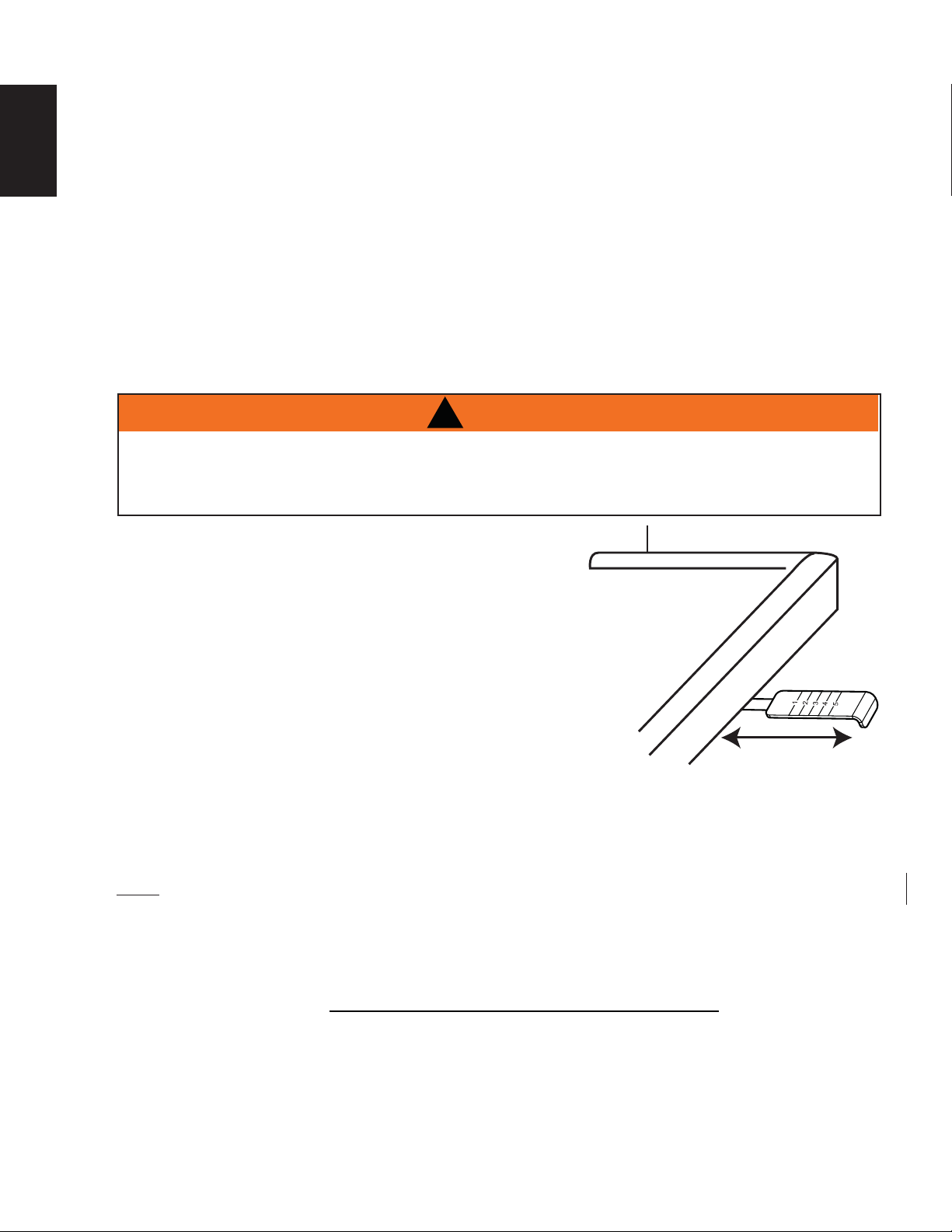
Adjusting the air control regulates the temperature. The draft can
be adjusted from a low burn rate with the handle in fully, to a high
burn rate with the handle fully out.
Inadequate draft may cause back-puffi ng into the room through
the appliance and chimney connector points and may cause
plugging of the chimney. Too much draft may cause an excessive
temperature in the appliance, glowing red appliance parts or
chimney connectors or an uncontrollable burn which can lead to a
chimney fi re or permanent damage to the appliance.
Do not operate your appliance for longer than 30 minutes with the draft control on “HIGH” (fully open).
H
I
G
H
LO
W
ASH LIP
7.2 AIR CONTROL
!
WARNING
7.3 FIRE EXTINGUISHERS / SMOKE & CARBON MONOXIDE DETECTORS
91.1A
All homes with a solid fuel burning appliance should have at least one fi re extinguisher in a central location,
known to all and at least one smoke detector and carbon monoxide (CO) detector in the room containing the
appliance. If the smoke detector sounds an alarm, correct the cause but do not de-activate or relocate the
smoke detector. If the carbon monoxide detector sounds an alarm, immediately vent the area, evacuate and
call your local fi re department.
THIS WOOD APPLIANCE HAS A MANUFACTURER-SET MINIMUM LOW BURN RATE AND MAXIMUM
HIGH BURN RATE THAT MUST NOT BE ALTERED. IT IS AGAINST FEDERAL REGULATIONS IN THE
UNITED STATES TO ALTER THIS SETTING OR OTHERWISE OPERATE THIS WOOD APPLIANCE IN A
MANNER INCONSISTENT WITH OPERATING INSTRUCTIONS IN THIS MANUAL.
NOTE: Always check your smoke and CO detectors are working properly.
W415-1476 / A / 09.30.16
25
EN
7.4 FUEL
!
WARNING
DO NOT STORE FUEL WITHIN THE CLEARANCE TO COMBUSTIBLES, OR IN THE SPACE REQUIRED
FOR RE-FUELING AND ASH REMOVAL.
BURNING WET, UNSEASONED WOOD CAN CAUSE EXCESSIVE CREOSOTE ACCUMULATION. WHEN
IGNITED IT CAN CAUSE A CHIMNEY FIRE THAT MAY RESULT IN A SERIOUS HOUSE FIRE.
Maximum heat for minimum fuel (optimum burn) occurs when the appliance top temperature is between 500°F
(260°C) and 600°F (315°C). The bricks will be nearly all white and the glass mostly clear. The whiteness of the
bricks and the cleanliness of the glass are good indicators of your operating effi ciency. Not enough heat is
produced when only one or two pieces of wood are burned or the wood may not burn completely. A minimum
of three pieces are needed to encase a bed of coals that sustains the fi re.
Loosely stacked wood burns quicker than a tightly packed load. Wood burns in cycles rather than giving a
steady output of heat. It is best to plan these cycles around your household routine so that only enough coals
are left to start the next load. In the evening, load your appliance, at least, a half-hour before bed to ensure a
good fi re, hot enough to close the draft control for an overnight burn.
Burn only dry seasoned wood with 20% moisture content. It produces more heat and less soot or creosote.
Do not burn ocean beach wood. Its salt content can produce a metal eating acid. When refueling open the
door slowly to prevent smoke spillage. Use a pair of long gloves (barbecue gloves) when feeding the fi re.
Because these appliances burn from the front to back, they are clean and effi cient, but they are also very hot
and gloves are useful. Keep a small steel shovel nearby to use as a poker and to remove ashes. Do not store
the wood within 3 feet (1m) of the appliance.
93.1
A fl ash fi re is a small fi re burned quickly when you don't need much
heat. After your kindling has "caught", load at least 3 pieces of wood,
stacked loosely. Burn with the draft control fully open or closed only
slightly.
7.5 LIGHTING A FIRE
7.5.1 FLASH FIRE
7.5.2 EXTENDED FIRE
82.1
Load your larger pieces of wood so they are tightly packed, close enough to prevent the fl ames from
penetrating it completely. After approximately 30 minutes, depending on the size of the load, close the draft
control completely making sure that the fi re is not extinguished.
DO NOT OVERFIRE THE APPLIANCE!
Overfi ring can occur by:
A. Burning large amounts of smaller wood pieces such as furniture scraps, skids or treated wood;
B. Vigorously burning large loads of wood with the draft control on “HIGH” (fully open) for long periods of
time (one or two hours).
C. Operating the appliance with the ash dump door blocked open or a poor gasket seal on the main door.
W415-1476 / A / 09.30.16
26
EN
Allow the ashes in your fi rebox to accumulate to a depth of two or three inches (51mm - 76mm); they tend to
burn themselves up. When the fi re has burned down and cooled, remove any excess ashes but leave an ash
bed approximately 1 inch (25mm) deep on the fi rebox bottom to help maintain a hot charcoal bed.
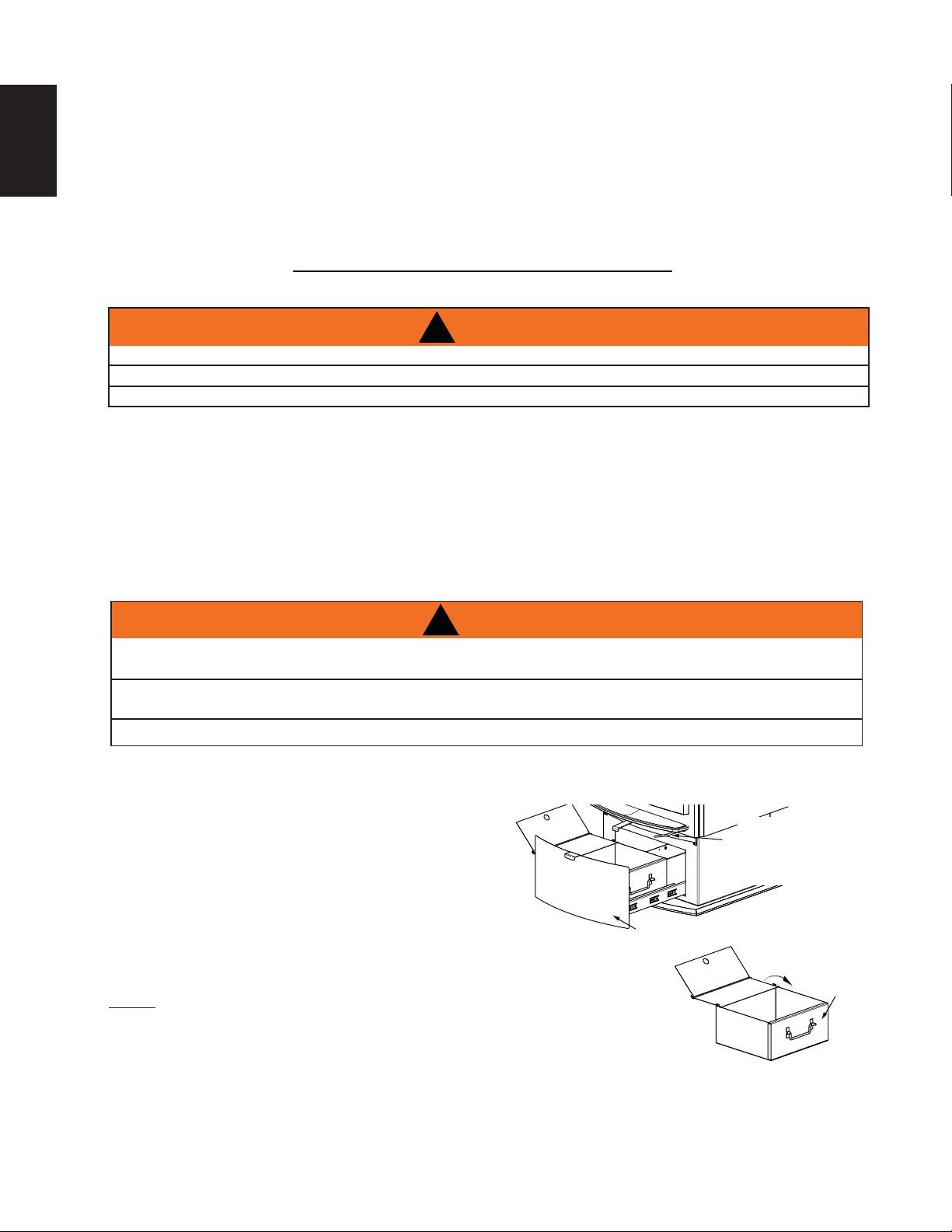
To use your ash pan, pull the ash dump handle forward,
rotate approximately 90° counterclockwise to the open
position. Rake the excess ashes into the ash pan. Close the
ash well making sure that no coals or foreign objects are
preventing the ash plug or well door from closing.
This creates a fi re hazard that may result in a house/chimney
fi re, internal damage to the stove or discoloration to the gold
plated door (plated fi nishes are not covered by the warranty). To
ensure that the ash well is fully closed, allow the door to snap shut,
dislodging anything that may be stuck at the opening.
NOTE: ALWAYS ENSURE THE ASH PAN IS COMPLETELY COOL PRIOR TO
REMOVING IT FROM THE ASH DRAWER.
Pull the ash drawer forward to open, this gains access to the ash pan. Remove the ash
pan by lifting it up and to the left or right side of the ash drawer. Temporarily place the
ash pan on a non-combustible surface and close the ash pan lid. Remove the ash pan
and safely dispose of the ashes.
Before reinstalling the ash pan ensure that the ash pan lid is OPEN. Place the ash pan into the ash drawer and
then close the ash drawer.
NEVER OPERATE YOUR STOVE WITH THE ASH WELL IN AN OPEN OR AJAR POSITION.
ASH PAN
LID
TO OPEN:
PULL AND ROTATE
TO CLOSE:
ROTATE IN OPPOSITE
DIRECTION
ASH DRAWER
ASH PAN
!
WARNING
TURN OFF THE POWER BEFORE SERVICING THE APPLIANCE.
APPLIANCE MAY BE HOT, DO NOT SERVICE UNTIL APPLIANCE HAS COOLED.
DO NOT USE ABRASIVE CLEANERS.
Check your chimney and chimney connector for creosote and soot buildup weekly until a safe frequency for
cleaning is established.
If accumulation is excessive, disconnect the appliance and clean both the chimney and the appliance. You
may want to call a professional chimney sweep to clean them. Both have to be cleaned at least once a year
or as often as necessary.
- Inspect the secondary air tubes.
- Remove fi bre baffl es and clean above them once a year. Replace any broken bricks.
- Inspect and replace all the gaskets, as required.
- Disassemble, clean and lubricate the door handle assembly.
!
WARNING
IMPROPER DISPOSAL OF ASHES RESULT IN FIRES. DO NOT DISCARD ASHES IN CARDBOARD
BOXES, DUMP IN BACKYARDS, OR STORE IN GARAGES.
IF USING A VACUUM TO CLEAN UP ASHES, BE SURE THE ASHES ARE ENTIRE COOLED. USING A
VACUUM TO CLEAN UP WARM ASHES COULD CAUSE A FIRE INSIDE THE VACUUM.
NEVER OPERATE YOUR APPLIANCE WITH THE ASH PLUG (IF APPLICABLE) REMOVED.
7.6 SMOKING
83.1A
A properly installed appliance should not smoke. If yours does, check the following:
• Has the chimney had time to get hot?
• Is the smoke passage blocked anywhere in the appliance, chimney connector or chimney?
• Is the room too airtight and the air intake not connected to the outside? Try with a window partly open.
• Is the smoke fl ow impeded by too long a horizontal pipe or too many bends?
• Is it a weak draft perhaps caused by a leaky chimney, a cold outside chimney, too large a diameter of a
chimney, too short a chimney, or a chimney too close to trees or a higher roof?
• Is the moisture content of the wood greater than 20%?
• If equipped, has the catalyst bypass been closed or closed prematurely?
8.0 MAINTENANCE
8.1 ASH REMOVAL PROCEDURES
W415-1476 / A / 09.30.16
27
EN
8.2 CREOSOTE FORMATION AND REMOVAL
84.1A
When wood is burned slowly, it produces tar and other organic vapors, which combine with expelled moisture
to form creosote. The creosote vapors condense in the relatively cooler chimney fl ue of a slow-burning fi re. As
a result, creosote residue accumulates on the fl ue lining. When ignited this creosote makes an extremely hot
fi re.
The chimney connector and chimney should be inspected at least once every two months during the heating
season to determine if a creosote buildup has occurred.
If creosote has accumulated it should be removed to reduce the risk of a chimney fi re.
8.3 RUNAWAY OR CHIMNEY FIRE
85.1
Runaway fi res can be the result of three major factors:
• Using incorrect fuel, or small fuel pieces which would normally be used as kindling.
• Leaving the door ajar too long and creating extreme temperatures as the air rushes in the open door.
• Burning your appliance with the ash plug not securely seated.
SOLUTIONS:
• Do not burn treated or processed wood, coal, charcoal, coloured paper or cardboard.
• Be careful not to over-fi re the appliance by leaving the door open too long after initial start-up. A
thermometer on the chimney connector and/or appliance top helps.
• Always operate the appliance with the ash plug properly installed.
IN CASE OF A CHIMNEY FIRE:
• Have a well understood plan for evacuation and a place outside for everyone to meet. Prepare to
evacuate to ensure everyone’s safety.
• Close air control on appliance.
• Call local fi re department. Have a fi re extinguisher handy. Contact local authorities for further
information on how to handle a chimney fi re.
• After the chimney fi re is out, clean and inspect the chimney for stress cracks prior to lighting another
fi re. Also check combustibles around the chimney and the roof.
!
WARNING
A CHIMNEY FIRE CAN PERMANENTLY DAMAGE YOUR CHIMNEY SYSTEM. THIS DAMAGE CAN
ONLY BE REPAIRED BY REPLACING THE DAMAGED COMPONENT PARTS. CHIMNEY FIRES ARE
NOT COVERED BY THE LIFETIME LIMITED WARRANTY.
8.4 CHIMNEY CLEANING
86.1
Both the chimney and the appliance must be inspected and cleaned if necessary at least once a year.
For serious wood burners, chimney cleaning must be done as needed to avoid chimney fi res; the venting
systems for controlled combustion appliances may need cleaning as often as once a month. These rates,
however, depend on the burning habits of the individual operating the appliance. For example, it is possible to
clog a solid fuel appliance chimney in a few days if slow, smoldering fi res are burned and the chimney is cold.
NOTE: Appliances burned consistently without hot fi res may result in signifi cant creosote
accumulations in the chimney.
Certain items and considerations are important in chimney cleaning:
• Proper tools should be used, including a brush specifi cally designed for chimney cleaning.
• The chimney connector and dampers as well as the chimney should be cleaned.
• The appliance’s fi rebox and baffl e system should be cleaned if needed.
• The chimney should be inspected and repairs made if needed, preferably by a qualifi ed chimney
sweep or mason.
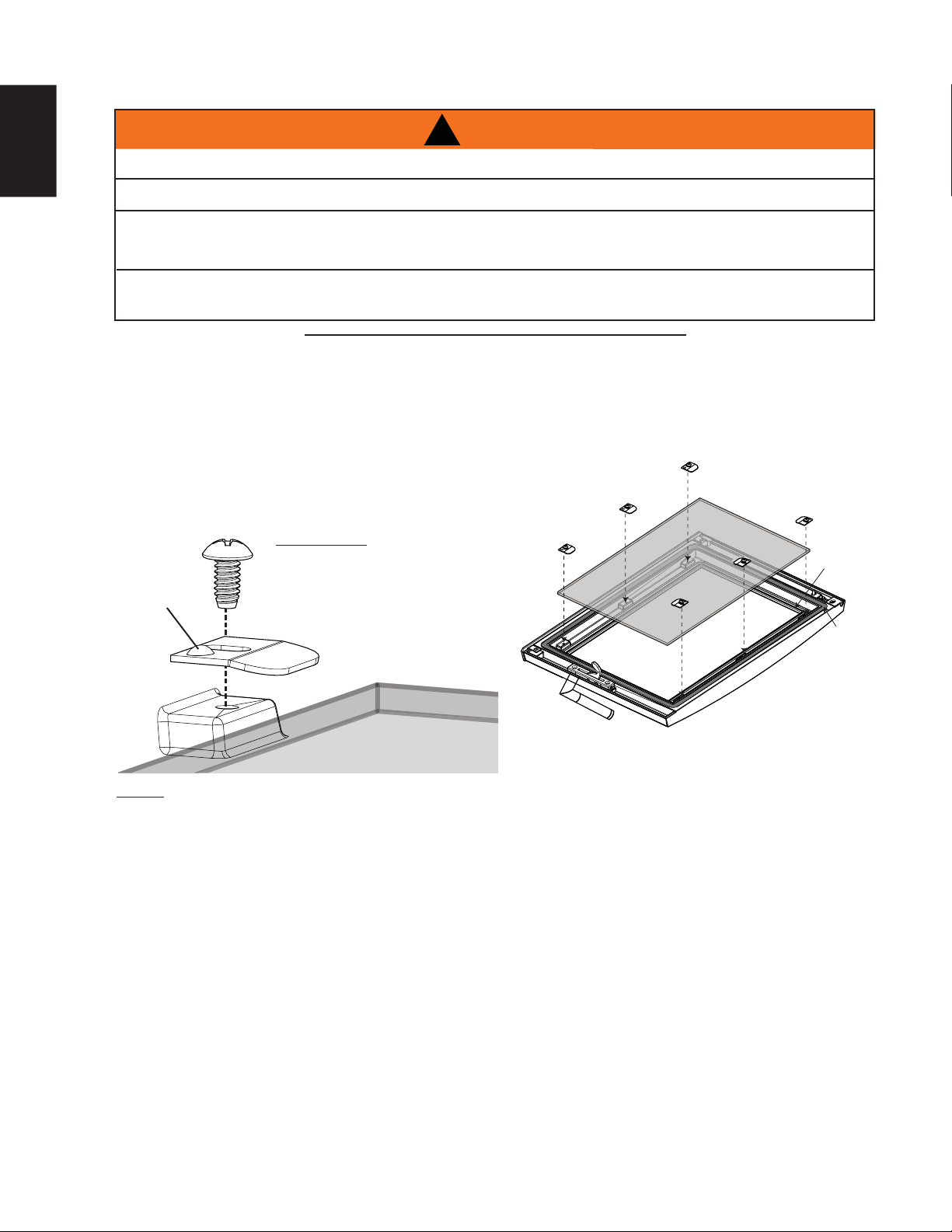
W415-1476 / A / 09.30.16
28
EN
!
WARNING
DO NOT USE SUBSTITUTE MATERIALS.
GLASS MAY BE HOT, DO NOT TOUCH GLASS UNTIL COOLED.
CARE MUST BE TAKEN WHEN REMOVING AND DISPOSING OF ANY BROKEN DOOR GLASS OR
DAMAGED COMPONENTS. BE SURE TO VACUUM UP ANY BROKEN GLASS FROM INSIDE THE
APPLIANCE BEFORE OPERATION.
DO NOT STRIKE, SLAM OR SCRATCH GLASS. DO NOT OPERATE APPLIANCE WITH GLASS
REMOVED, CRACKED, BROKEN OR SCRATCHED.
56.2
8.5 GLASS REPLACEMENT
A. When the appliance is cool, remove the door from the appliance, refer to the “DOOR REMOVAL/
INSTALLATION” section. Place the door face down careful not to scratch the paint.
B. Remove the 6 screws (W570-0085) and the 6 glass retainers (W500-0692). Remove the glass from
the appliance.
C. Replace door and/or glass gaskets, if necessary. Secure into position using red silicone.
D. Place the glass in position and re secure the 6 glass retainers, do not
overtighten. Refer to “DOOR REMOVAL/INSTALLATION” section
for proper door installation instructions.
NOTE: For replacement glass see “REPLACEMENTS” section.
GLASS
GASKET
DOOR
GASKET
DIMPLE
IMPORTANT: ENSURE THE
RETAINER HAS THE DIMPLE
FACING UPWARDS, AS SHOWN.
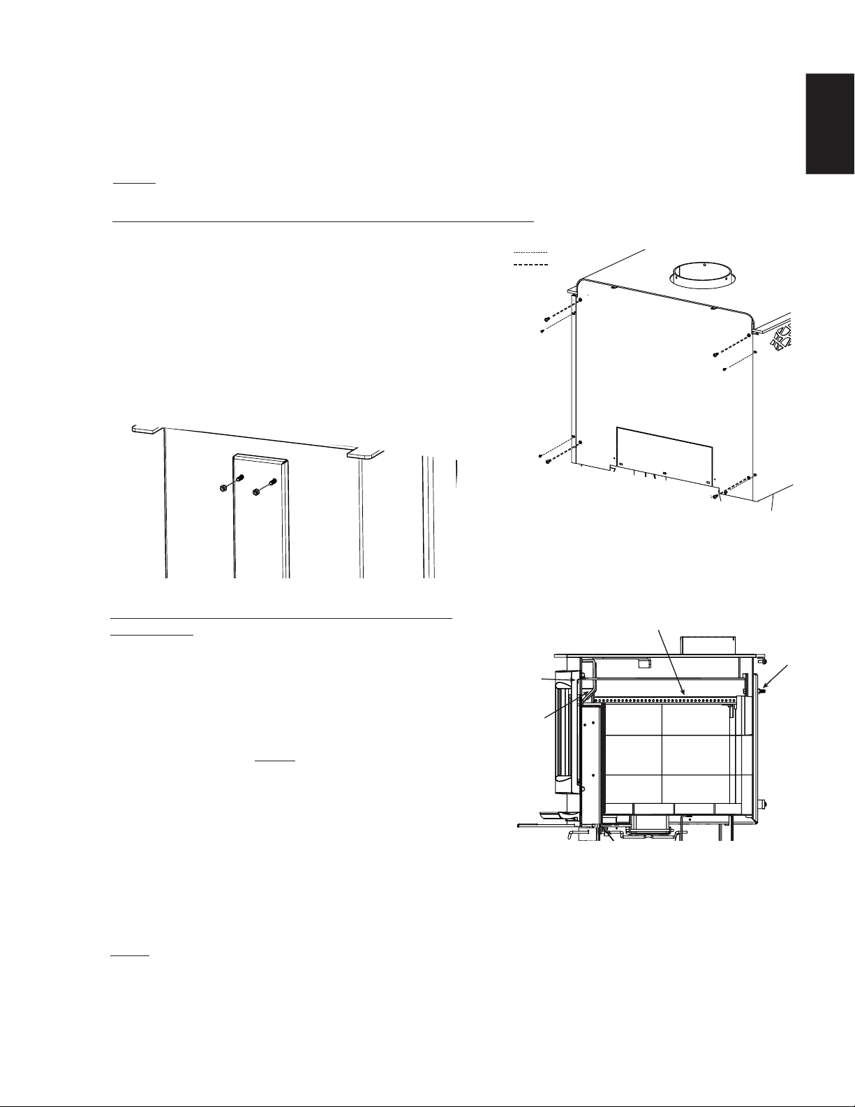
W415-1476 / A / 09.30.16
29
EN
8.6 SECONDARY AIR MANIFOLD REPLACEMENT
At the end of each burning season inspect the secondary air manifold for warping or deterioration. Replace if
necessary. At this time also check that the door gasket is not worn, frayed or loose. Replace with 1/2" (13mm)
high density fi breglass rope if necessary. Check the airwash gasket located inside the appliance above the
door, replace if deteriorated. Contact your Napoleon dealer for specifi c type and size of the materials required.
NOTE: Do not operate appliance if the manifold, airwash shield or fi bre baffl e is deteriorated or missing.
To reinstall the secondary air manifold follow these
instructions:
A. Locate the slot at the front of the fi rebox chamber, as
illustrated.
B. Insert the tab of the secondary air manifold into the
above mentioned slot and pivot the secondary air
manifold into position.
C. A new gasket MUST be installed between the
secondary air manifold and fi rebox.
D. Insert one of the bolts to hold the secondary air
manifold in place.
E. Working from the inside of the fi rebox, take the second
bolt and install it into position, loosely secure the washer and nut.
F. Remove the fi rst bolt and reinstall as previously described in step E. Fully tighten both nuts and bolts.
G. Reinstall the baffl es and bricks.
H. To reinstall the rear and side shields, refer to steps A and B of the removal instructions.
NOTE: PUSH THE BAFFLE ALL THE WAY TO THE REAR OF THE FIREBOX, LEAVING A MINIMUM
OF 1” (25mm) GAP ALONG THE FRONT. THIS WILL ALLOW FLUE GASES TO PROPERLY ESCAPE THE
FIREBOX.
To remove the secondary air manifold follow these instructions:
A. Remove the screws securing the side shields, slide
them forward and remove from the appliance.
B. Remove the screws securing the rear shield, then
remove the shield from the appliance.
C. Remove the rear bricks, then remove the baffl e.
D. Remove the 2 nuts and bolts securing the
secondary air manifold in place, refer to the
illustration below.
E. Remove the secondary air manifold and gasket.
AIRWASH
SHEILD
AND
GASKET
SLOT
SECONDARY AIR MANIFOLD
NUT AND
BOLT(x2)
SIDE VIEW
A
B

W415-1476 / A / 09.30.16
30
EN
If the glass is not kept clean permanent discolouration and / or
blemishes may result. Normally a hot fi re will clean the glass.
The most common reasons for dirty glass include: not using
suffi cient fuel to get the appliance thoroughly hot, using green
or wet wood, closing the draft so far that there is insuffi cient air
for complete combustion.
If it is necessary to clean the glass, buff lightly with a clean dry
cloth and non-abrasive cleaner.
DO NOT CLEAN GLASS WHEN HOT! Clean the glass after the fi rst 10 hours of operation with a
recommended appliance glass cleaner. Thereafter clean as required.
The glass is very strong but do not let burning fuel rest or fall against it and always close the door gently.
NEVER FORCE IT SHUT!
If the glass should ever crack or break while the fi re is burning, do not open the door until the fi re is out and do
not operate the appliance again until the glass has been replaced. Available from your Authorized dealer.
DO NOT SUBSTITUTE MATERIALS.
5.3
HOT GLASS WILL
CAUSE BURNS.
DO NOT TOUCH GLASS
UNTIL COOLED.
NEVER ALLOW CHILDREN
TO TOUCH GLASS.
!
WARNING
6.1
If the appliance is equipped with plated parts, you must clean fi ngerprints or other marks from the plated
surfaces before operating the appliance for the fi rst time. Use a glass cleaner or vinegar and towel to clean.
If not cleaned properly before operating for the fi rst time, the marks can cause permanent blemishes on the
plating. After the plating is cured, the fi ngerprints and oils will not affect the fi nish and little maintenance
is required, just wipe clean as needed. Prolonged high temperature burning with the door ajar may cause
discolouration on plated parts.
NOTE: The protective wrap on plated parts is best removed when the assembly is at room temperature
but this can be improved if the assembly is warmed, using a hair dryer or similar heat source.
8.7 CARE OF GLASS
8.8 CARE OF PLATED PARTS
5.5.1A
This appliance is factory equipped with 5mm ceramic glass. Use only replacement parts as supplied by the
appliance manufacturer. DO NOT SUBSTITUTE MATERIALS.
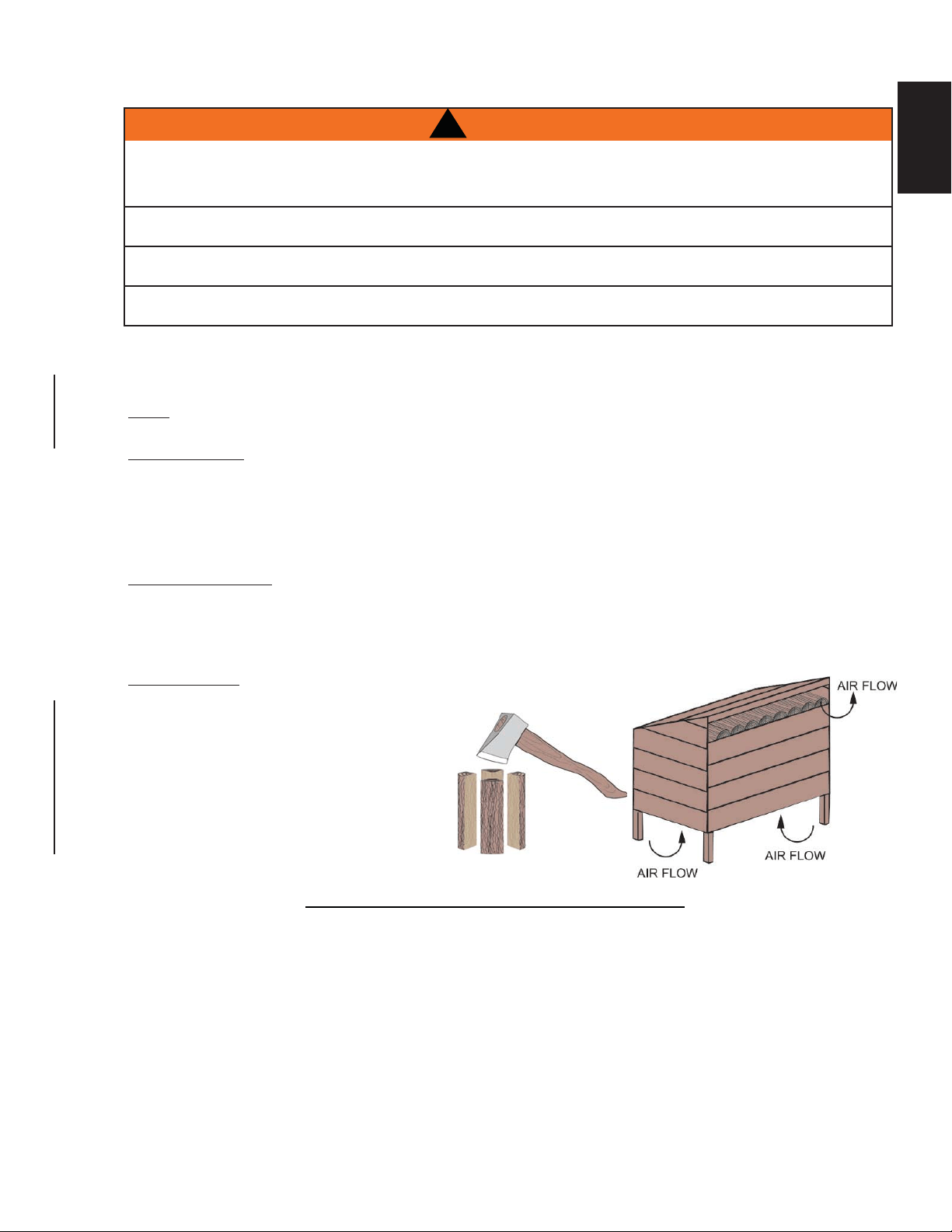
W415-1476 / A / 09.30.16
31
EN
8.9 WOOD
87.1E
When loading the appliance, ensure that the upper fi bre baffl e is situated properly. For maximum effi ciency, when the appliance
is thoroughly hot, load it fully to the top of the door opening and burn at a medium low setting. The whiteness of the bricks
and the cleanliness of the glass are good indicators of your operating effi ciency. Not enough heat is produced when only a few
pieces of wood are burned or the wood may not burn completely.
NOTE: When loading the appliance, ensure to keep fuel back from the glass. If coals are to accumulate on the front lip,
there is a chance they will fall out when the door is opened.
TYPES OF WOOD
Both hardwood and softwood burn equally well in this appliance but hardwood is denser, will weigh more per cord and burn a
little slower and longer.
Manufactured fi relogs made by compressing 100% natural wood fi bre can be safely used as fuel. Do not use manufactured
fi relogs if they contain additives such as paraffi n, wax, binders etc. Never burn more than two manufactured fi relogs at a
time.
MOISTURE CONTENT
Burn only dry, clean unpainted wood that has been seasoned. It produces more heat and less soot or creosote. Freshly cut
wood contains about 50% moisture while after proper seasoning only about 20% of the water remains. As wood is burned,
this water boils off consuming energy that should be used in heating. The wetter the wood, the less heat is given off and the
more creosote is produced. Dry fi rewood has cracks in the end of the grain.
STORING WOOD
Firewood should be split and stacked in a manner
that allows for full air circulation and covered in early
spring to be ready for burning that fall. Dry fi rewood
has cracks in the end grain.
Cut the wood so that it will fi t horizontally, front
to back, making for easier loading and less of a
likelihood that the wood will roll onto the glass.
Fuel for the appliance must not be stored closer
than the required clearances to combustibles (heat
sensitive material). NEVER STORE WOOD IN THE
ASH PAN COMPARTMENT (if applicable).
!
WARNING
THIS APPLIANCE IS DESIGNED TO BURN NATURAL WOOD ONLY. DO NOT BURN TREATED
WOOD, COAL, CHARCOAL, COLOURED PAPER, CARDBOARD, SOLVENTS OR GARBAGE. THIS
APPLIANCE HAS NOT BEEN TESTED WITH AN UNVENTED GAS LOG SET. TO REDUCE RISK OF FIRE OR INJURY, DO NOT
INSTALL AN UNVENTED GAS LOG SET INTO THE APPLIANCE.
HIGHER EFFICIENCIES AND LOWER EMISSIONS GENERALLY RESULT WHEN BURNING AIR DRIED SEASONED HARDWOODS,
AS COMPARED TO SOFTWOODS OR TOO GREEN OR FRESHLY CUT HARDWOODS.
BURNING WET UNSEASONED WOOD CAN CAUSE EXCESSIVE CREOSOTE ACCUMULATION. WHEN IGNITED IT CAN CAUSE A
CHIMNEY FIRE THAT MAY RESULT IN A SERIOUS HOUSE FIRE.
DO NOT STORE FUEL WITHIN THE CLEARANCE TO COMBUSTIBLES, OR IN THE SPACE REQUIRED FOR RE-FUELING AND
ASH REMOVAL.

W415-1476 / A / 09.30.16
32
EN
9.0 REPLACEMENTS
41.1C
Contact your dealer for questions concerning prices and policies on replacement parts. Normally, all parts
can be ordered through your Authorized dealer / distributor.
FOR WARRANTY REPLACEMENT PARTS, A PHOTOCOPY OF THE ORIGINAL INVOICE WILL BE
REQUIRED TO HONOUR THE CLAIM.
When ordering replacement parts always give the following information:
• Model & Serial Number of appliance
• Installation date of appliance
• Part number
• Description of part
• Finish
PARTS, PART NUMBERS AND AVAILABILITY ARE SUBJECT TO CHANGE WITHOUT NOTICE.
PARTS IDENTIFIED AS STOCKED WILL BE DELIVERED WITHIN 2 TO 5 BUSINESS DAYS FOR MOST
DELIVERY DESTINATIONS.
PARTS NOT IDENTIFIED AS STOCKED WILL BE DELIVERED WITHIN A 2 TO 4 WEEK PERIOD, FOR
MOST CASES.
PARTS IDENTIFIED AS ‘SO’ ARE SPECIAL ORDER AND CAN TAKE UP TO 90 DAYS FOR DELIVERY.
FAILURE TO POSITION THE PARTS IN ACCORDANCE WITH THIS MANUAL OR FAILURE TO USE
ONLY PARTS SPECIFICALLY APPROVED WITH THIS APPLIANCE MAY RESULT IN PROPERTY
DAMAGE OR PERSONAL INJURY.
!
WARNING
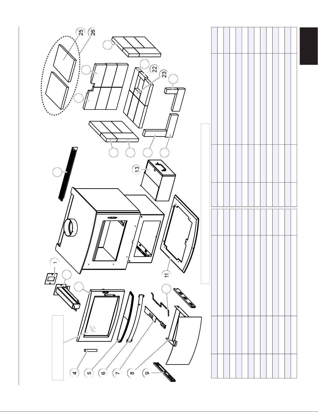
W415-1476 / A / 09.30.16
33
EN
1
11
18
2
4
8
13
12
3
9
10
5
6
17
16
19
24
22
15
23
20
25
7
14
21
1
11
25
2
4
8
13
12
3
9
10
5
6
17
16
18
23
21
15
22
19
24
7
14
20
FOR REPLACEMENTS PARTS
REFER TO: "DOOR ASSEMBLY"
S1
OVERVIEW
REF. NO. PART NUMBER DESCRIPTION
1 W290-0219 AIR MANIFOLD GASKET
2 W432-0144 AIR MANIFOLD
3 W010-3194 DOOR ASSEMBLY
4 W325-0081 DOOR SLEEVE
5 W135-0238-SER ASH LIP
6 W200-0415-SER ASH DRAWER COVER
7 W010-3094 AIR CONTRO
L
8 W010-3043 ASH DRAWER
9 W610-0010 DRAWER SLIDE
10 W325-0017 ASHWELL HANDLE
11 W495-0048-SER PEDESTAL BASE
12 W200-0414-SER REAR SHIELD COVER
13 W010-1534 ASH PAN
REF. NO. PART NUMBER DESCRIPTION
14 W090-0003 BRICK (1.25" x 4.5" x 4.5")
15 W090-0001 BRICK (1.25" x 4.5" x 9")
16 W090-0018 BRICK (1.25" x 2.25" x 9")
17 W090-0002 BRICK (1.25" x 3" x 9")
18
19
20
21
22
23
24
25
1826
STOCKED STOCKED
YES
YES
W090-0207 (LS) NOTCHED BRICK (1.25" x 4.5" x 9")
W090-0208 (RS) NOTCHED BRICK (1.25" x 4.5" x 9")
W090-0184 BRICK (1.25" x 4.5" x 8.25")
W090-0166 BRICK (1.25" x 3" x 9")
W090-0017 BRICK (1.25" x 1.5" x 4.5")
W090-0016 BRICK (1.25" x 2.5" x 4.5")
W090-0216 BRICK (1.25" x 1.75" x 4.75")
W018-0077 FIBRE BAFFLE
W010-3560
FIBRE BAFFLE KI
T
26
YES
YES
ITEMS MAY NOT APPEAR EXACTLY AS ILLUSTRATED
9.1 S1 OVERVIEW
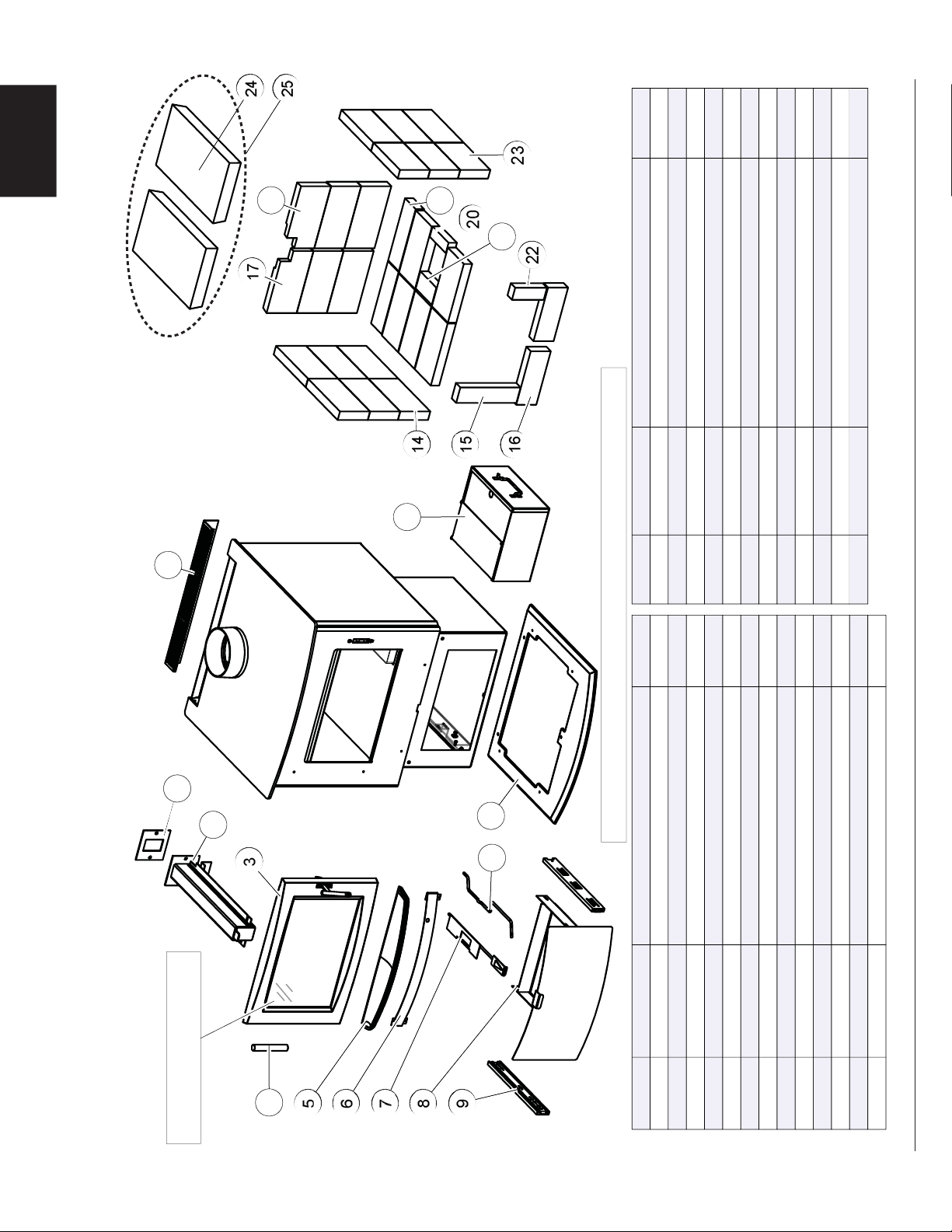
W415-1476 / A / 09.30.16
34
EN
1
8
2
11
12
4
7
10
6
3
5
9
18
16
13
20
15
19
14
22
21
24
23
1
8
2
11
12
4
7
10
6
3
5
9
17
16
13
19
15
18
14
21
20
23
22
FOR REPLACEMENTS PARTS
REFER TO: "DOOR ASSEMBLY"
1824
1825
S4 OVERVIEW
ITEMS MAY NOT APPEAR EXACTLY AS ILLUSTRATED
REF. NO.
PART NUMBER
DESCRIPTION
1
W290-0219
AIR MANIFOLD GASKET
2
W432-0142
AIR MANIFOLD
3
W010-3194
DOOR ASSEMBLY
4
W325-0081
DOOR SLEEVE
5
W135-0238-SER
ASH LIP
6
W200-0415-SER
ASH DRAWER COVER
7
W010-3098
AIR CONTROL
8
W010-3043
ASH DRAWER
9
W610-0010
DRAWER SLIDE
10
W325-0017
ASHWELL HANDLE
11
W495-0048-SER
PEDESTAL BASE
12
W200-0414-SER
REAR SHIELD COVER
13
W010-1534
ASH PAN
REF. NO.
PART NUMBER
DESCRIPTION
14
W090-0001
BRICK (1.25" x 4.5" x 9")
15
W090-0018
BRICK (1.25" x 2.25" x 9")
16
W090-0002
BRICK (1.25" x 3" x 9")
17
18
W090-0207
(LS) NOTCHED BRICK (1.25" x 4.5" x 9")
19
W090-0208
(RS) NOTCHED BRICK (1.25" x 4.5" x 9")
20
W090-0166
BRICK (1.25" x 3" x 9")
21
W090-0017
BRICK (1.25" x 1.5" x 4.5")
22
W090-0016
BRICK (1.25" x 2.5" x 4.5")
23
W090-0216
BRICK (1.25" x 1.75" x 4.75")
24
W090-0184
BRICK (1.25" x 4.5" x 8.25")
STOCKED
STOCKED
25
W018-0078
FIBRE BAFFLE
W010-3561
FIBRE BAFFLE KIT
YES
YES
YES
9.2 S4 OVERVIEW
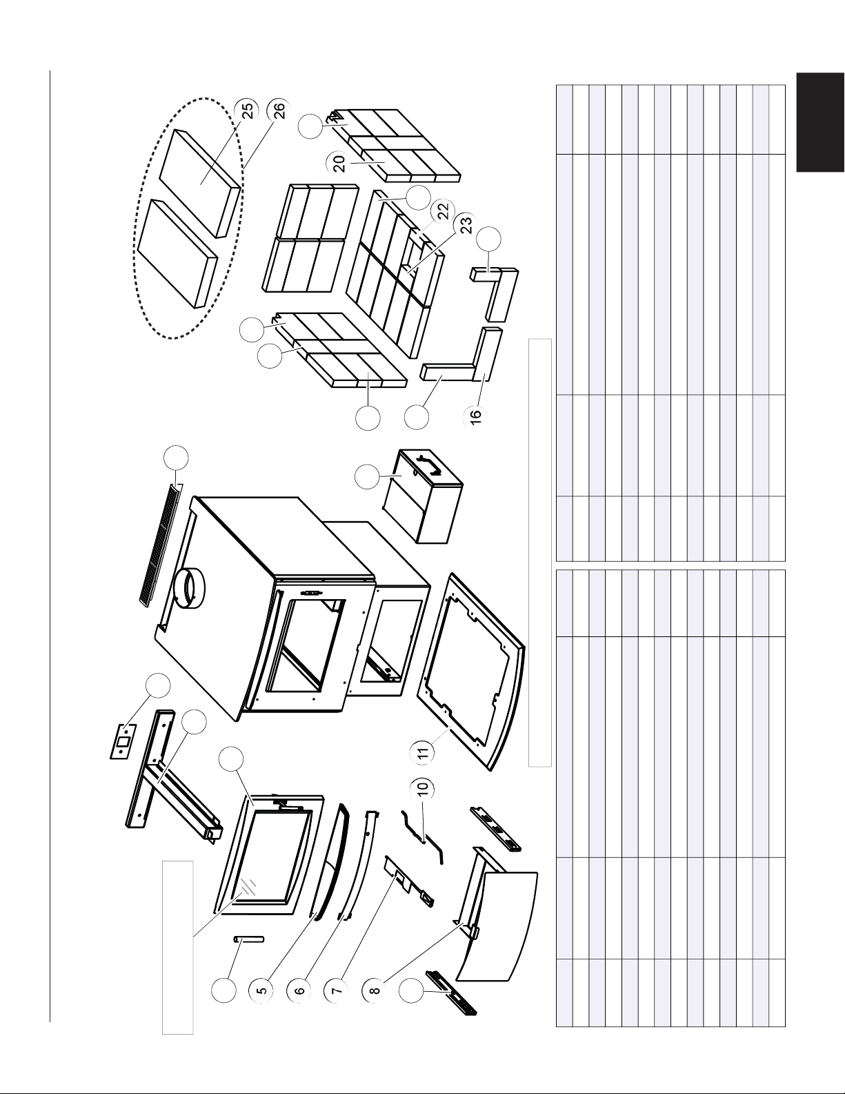
W415-1476 / A / 09.30.16
35
EN
26 W010-3562
7
11
1
8
10
5
2
6
4
12
3
13
9
18
20
16
17
15
22
14
21
23
25
24
7
11
1
8
10
5
2
6
4
12
3
13
9
18
21
16
17
15
23
14
22
24
19
20
S9 OVERVIEW
REF. NO. PART NUMBER DESCRIPTION
1 W290-0228 AIR MANIFOLD GASKET
2 W432-0130 AIR MANIFOLD
3 W010-3194 DOOR ASSEMBLY
4 W325-0081 DOOR SLEEVE
5 ASH LIP
6 ASH DRAWER COVER
7 W010-3095 AIR CONTRO
L
8 W010-3043 ASH DRAWER
9 W610-0010 DRAWER SLIDE (X2)
10 W325-0017 ASHWELL HANDLE
11 W495-0049 PEDESTAL BASE
12 REAR SHIELD COVER
13 W010-1534 ASH PAN
REF. NO. PART NUMBER DESCRIPTION
14 W090-0015 BRICK (1.25" x 4.5" x 9")
15 W090-0018 BRICK (1.25" x 2.25" x 9")
16 W090-0002 BRICK (1.25" x 3" x 9")
17 W090-0003 BRICK (1.25" x 4.5" X 4.5")
18 W090-0207 (LS) NOTCHED BRICK (1.25" x 4.5" x 9")
19
20 W090-0166 BRICK (1.25" x 3" x 9")
21 W090-0017 BRICK (1.25" x 1.5" x 4.5")
22 W090-0016 BRICK (1.25" x 2.5" x 4.5")
23 W090-0216 BRICK (1.25" x 1.75" x 4.75")
24 W090-0184 BRICK (1.25" x 4.5" x 8.25")
25
W090-0208 (RS) NOTCHED BRICK (1.25" x 4.5" X 9")
W018-0130 FIBRE BAFFLE
1825
1826
FIBRE BAFFLE KI
T
ITEMS MAY NOT APPEAR EXACTLY AS ILLUSTRATED
STOCKEDSTOCKED
YES
YES
FOR REPLACEMENTS PARTS
REFER TO: "DOOR ASSEMBLY"
W135-0238-SER
W200-0415-SER
W200-0414-SER
9.3 S9 OVERVIEW
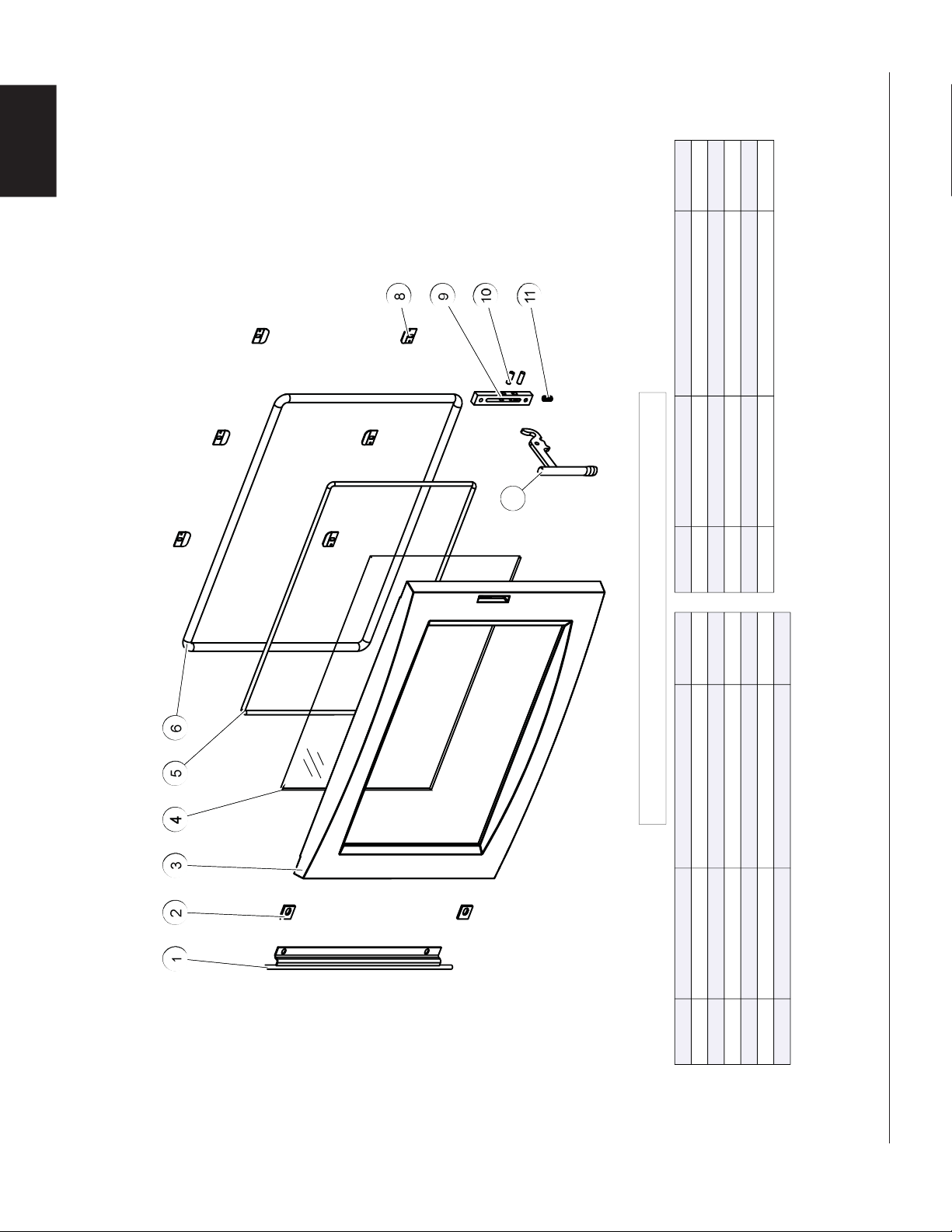
W415-1476 / A / 09.30.16
36
EN
8
6
5
4
1
2
3
11
9
10
8
6
5
4
1
2
3
11
9
10
ITEMS MAY NOT APPEAR EXACTLY AS ILLUSTRATED
REF. NO.
PART NUMBER
DESCRIPTION
1
W010-2947-SER
HINGE ASSEMBLY
2
W500-0705
DOOR HINGE RETAINER
3
W225-0313-SER
DOOR
4
W300-0168-SER
DOOR GLASS
5
W562-0070
GLASS GASKET KIT (1/4" DIA.)
6
W562-0071
DOOR GASKET KIT (1/2" DIA.)
REF. NO.
PART NUMBER
DESCRIPTION
7
W010-3078-CH4HF
DOOR HANDLE
8
W500-0709-SER
GLASS RETAINER
9
W060-0012-SER
LATCH BLOCK
10
W485-0052
DOWEL PIN
11
W630-0024
SPRING
77
STOCKED
YES
STOCKED
YES
YES
YES
YES
9.4 S1, S4 & S9 DOOR ASSEMBLY
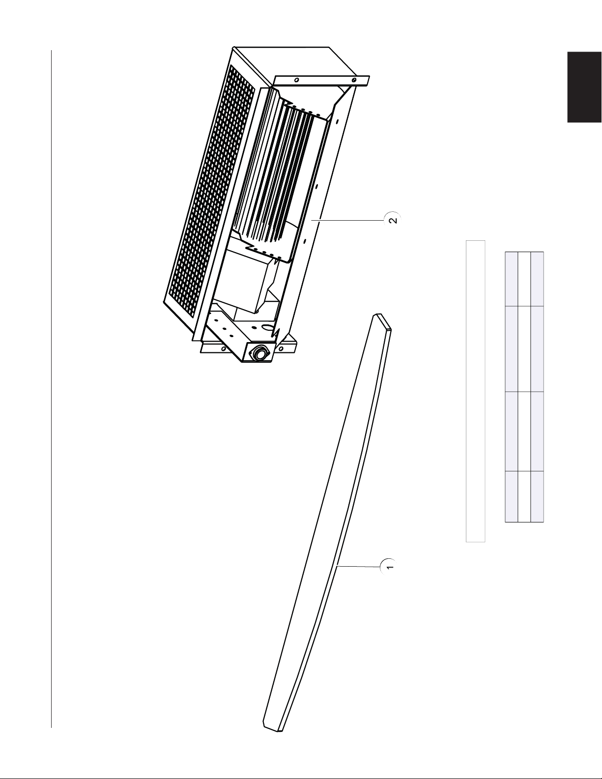
W415-1476 / A / 09.30.16
37
EN
2
1
2
1
ITEMS MAY NOT APPEAR EXACTLY AS ILLUSTRATED
REF. NO. PART NUMBER DESCRIPTION
1 W010-2944 DOOR TRIM
2 EP65 BLOWER KIT
STOCKED
10.0 S1, S4 & S9 ACCESSORIES

W415-1476 / A / 09.30.16
38
EN
11.0 TROUBLESHOOTING
!
WARNING
TURN OFF THE ELECTRICAL POWER BEFORE SERVICING THE APPLIANCE.
APPLIANCE MAY BE HOT, DO NOT SERVICE UNTIL APPLIANCE HAS COOLED.
DO NOT USE ABRASIVE CLEANERS.
WHEN CHECKING CONNECTIONS, INSTALLING JUMPER WIRES (FOR TEST PURPOSES ONLY) OR
REPLACING COMPONENTS, UNPLUG HEATER FROM THE RECEPTACLE TO PREVENT ELECTRICAL
SHOCK OR DAMAGE TO THE COMPONENT.
PROBLEM SOLUTION
Can’t get the fi re started. - Not enough kindling / paper? Add more.
- Not enough air? Ensure air control is fully open. Also ensure that the air
opening is not obstructed.
- Cold air blockage? Burn a piece of paper to establish a draft.
- Use dry seasoned wood with 20% moisture content.
- Flue blockage? Inspect chimney.
Smokes when door is
open.
- Cold air blockage? Burn a piece of paper to establish a draft.
- Insuffi cient draft? Add more pipe.
- Let air stabilize before opening door.
- Ensure baffl es are positioned correctly.
- Negative pressure? Open a window near the appliance.
Appliance emits odour. - Paint curing. See “GENERAL INSTRUCTIONS” section.
Stove doesn’t burn hot
enough.
- Wood has more than 20% moisture.
- Insuffi cient draft? Add more pipe.
- Not enough air? Ensure air control is fully open. Also ensure that the air
opening is not obstructed.
Wood burns too fast. - Air control may need to be adjusted down.
- Check to see ash plug is properly seated (if equipped).
- Check door gasket for adequate seal.
- Wood may be extremely dry.
Dirty glass. - Air control may be closed too far.
- Burn hotter, smaller fi res.
- Use well seasoned wood with 20% moisture content.
Blower does not run. - Appliance may not be up to temperature.
- Ensure blower has power.
Door latch is stiff. - Disassemble door latch and apply anti-seize lubricant to the spring.
Reassemble.

W415-1476 / A / 09.30.16
39
EN
12.0 WARRANTY
NAPOLEON® warrants its products against manufacturing defects to the original purchaser only. Registering your warranty is not necessary. Simply
provide your proof of purchase along with the model and serial number to make a warranty claim. Provided that the purchase was made through an
authorized NAPOLEON® dealer your appliance is subject to the following conditions and limitations:
Warranty coverage begins on the date of original installation.
This factory warranty is non-transferable and may not be extended whatsoever by any of our representatives.
The wood appliance must be installed by an authorized service technician or contractor. Installation must be done in accordance with the installation
instructions included with the product and all local and national building and fi re codes.
EPA approved products, where incorrect fuel is used, will void the warranty.
This limited warranty does not cover damages caused by misuse, lack of maintenance, accident, alterations, abuse or neglect and parts installed from
other manufacturers will nullify this warranty.
This limited warranty further does not cover any scratches, dents, corrosion or discoloring caused by excessive heat, abrasive and chemical cleaners nor
chipping on porcelain enamel parts, nor any venting components used in the installation of the appliance.
This warranty extends to the repair or replacement of warranted parts which are defective in material or workmanship provided that the product has been
operated in accordance with the operation instructions and under normal conditions.
After the fi rst year, with respect to the President’s Lifetime Limited Warranty, NAPOLEON may, at its discretion, fully discharge all obligations with respect
to this warranty by refunding to the original warranted purchaser the wholesale price of any warranted but defective part(s).
After the fi rst year, NAPOLEON will not be responsible for installation, labour or any other costs or expenses related to the reinstallation of a warranted
part, and such expenses are not covered by this warranty.
Notwithstanding any provisions contained in the President’s Lifetime Limited Warranty, NAPOLEON’s responsibility under this warranty is defi ned as
above and it shall not in any event extend to any incidental, consequential or indirect damages.
This warranty defi nes the obligations and liability of NAPOLEON with respect to the NAPOLEON wood appliance and any other warranties expressed or
implied with respect to this product, its components or accessories are excluded.
NAPOLEON neither assumes, nor authorizes any third party to assume, on its behalf, any other liabilities with respect to the sale of this product.
NAPOLEON will not be responsible for: over-fi ring, downdrafts, spillage caused by environmental conditions such as rooftops, buildings, nearby trees,
hills, mountains, inadequate vents or ventilation, excessive venting confi gurations, insuffi cient makeup air, or negative air pressures which may or may not
be caused by mechanical systems such as exhaust fans, furnaces, clothes dryers, etc.
Any damages to appliance, combustion chamber, heat exchanger, plated trim or other component due to water, weather damage, long periods of
dampness, condensation, damaging chemicals or cleaners will not be the responsibility of NAPOLEON.
NAPOLEON reserves the right to have its representative inspect any product or part thereof prior to honouring any warranty claim.
All parts replaced under the President’s Limited Lifetime Warranty Policy are subject to a single claim.
During the fi rst 10 years NAPOLEON will replace or repair the defective parts covered by the lifetime warranty at our discretion free of charge. From 10
years to life, NAPOLEON will provide replacement parts at 50% of the current retail price.
All parts replaced under the warranty will be covered for a period of 90 days from the date of their installation.
The manufacturer may require that defective parts or products be returned or that digital pictures be provided to support the claim. Returned products are
to be shipped prepaid to the manufacturer for investigation. If a product is found to be defective, the manufacturer will repair or replace such defect.
Before shipping your appliance or defective components, your dealer must obtain an authorization number. Any merchandise shipped without authorization
will be refused and returned to sender.
Shipping costs are not covered under this warranty.
Additional service fees may apply if you are seeking warranty service from a dealer.
Warranty labour allowance is only for the replacement of the warranted part. Travel, diagnostic tests, shipping and other related charges are not covered
by this warranty.
2.2E
NAPOLEON products are manufactured under the strict Standard of the world recognized ISO 9001 : 2008 Quality Assurance
Certifi cate.
NAPOLEON products are designed with superior components and materials, assembled by trained craftsmen who take great
pride in their work. The complete appliance is again thoroughly inspected by a qualifi ed technician before packaging to ensure
that you, the customer, receives the quality product that you expect from NAPOLEON.
The following materials and workmanship in your new NAPOLEON wood appliance are warranted against defects for as long as
you own the appliance. This covers: combustion chamber, heat exchanger, ceramic glass (thermal breakage only), gold plated parts
against tarnishing, porcelainized enameled components, aluminum extrusion trims, vortex baffl es, ash drawer and iron castings.
Electrical (110V)
components and wearable parts are covered and NAPOLEON will provide replacement parts free of
charge during the fi rst year of the limited warranty. This covers:
blowers, thermal switch, switches, wiring, fi rebrick, stainless
steel baffl e retainer, secondary air tubes and gasketing. *
Labour related to warranty repair is covered free of charge during the fi rst year. Repair work, however, requires the prior approval of
an authorized company offi cial. Labour costs to the account of NAPOLEON are based on a predetermined rate schedule and any
repair work must be done through an authorized NAPOLEON dealer.
Parts such as fi rebricks and baffl es should routinely be removed by the operator as part of the regular service and therefore, any
warranty replacement of these parts does not qualify for any labour allowances.
* Construction of models vary. Warranty applies only to components included with your specifi c appliance.
NAPOLEON WOOD APPLIANCE PRESIDENT’S LIFETIME LIMITED WARRANTY
CONDITIONS AND LIMITATIONS
ALL SPECIFICATIONS AND DESIGNS ARE SUBJECT TO CHANGE WITHOUT PRIOR NOTICE DUE TO ON-GOING PRODUCT
IMPROVEMENTS. NAPOLEON IS A REGISTERED TRADEMARK OF WOLF STEEL LTD.
Other Napoleon
®
Products
'JSFQMBDF*OTFSUTt$IBSDPBM(SJMMT
t(BT'JSFQMBDFTt8BUFSGBMMTt8PPE4UPWFT
)FBUJOH$PPMJOHt&MFDUSJD'JSFQMBDFTt0VUEPPS'JSFQMBDFTt(BT(SJMMT
'JSFQMBDFT)FBUJOH$PPMJOHDBMMt(SJMMTDBMM
napoleonproducts.com
/BQPMFPO3PBE#BSSJF0OUBSJP$BOBEB-.(
#BZWJFX%SJWF#BSSJF0OUBSJP$BOBEB-/:
.JMMFS%SJWF$SJUUFOEFO,FOUVDLZ64"
5SBOT$BOBEB)JHIXBZ.POUSFBM2VFCFD$BOBEB)5"
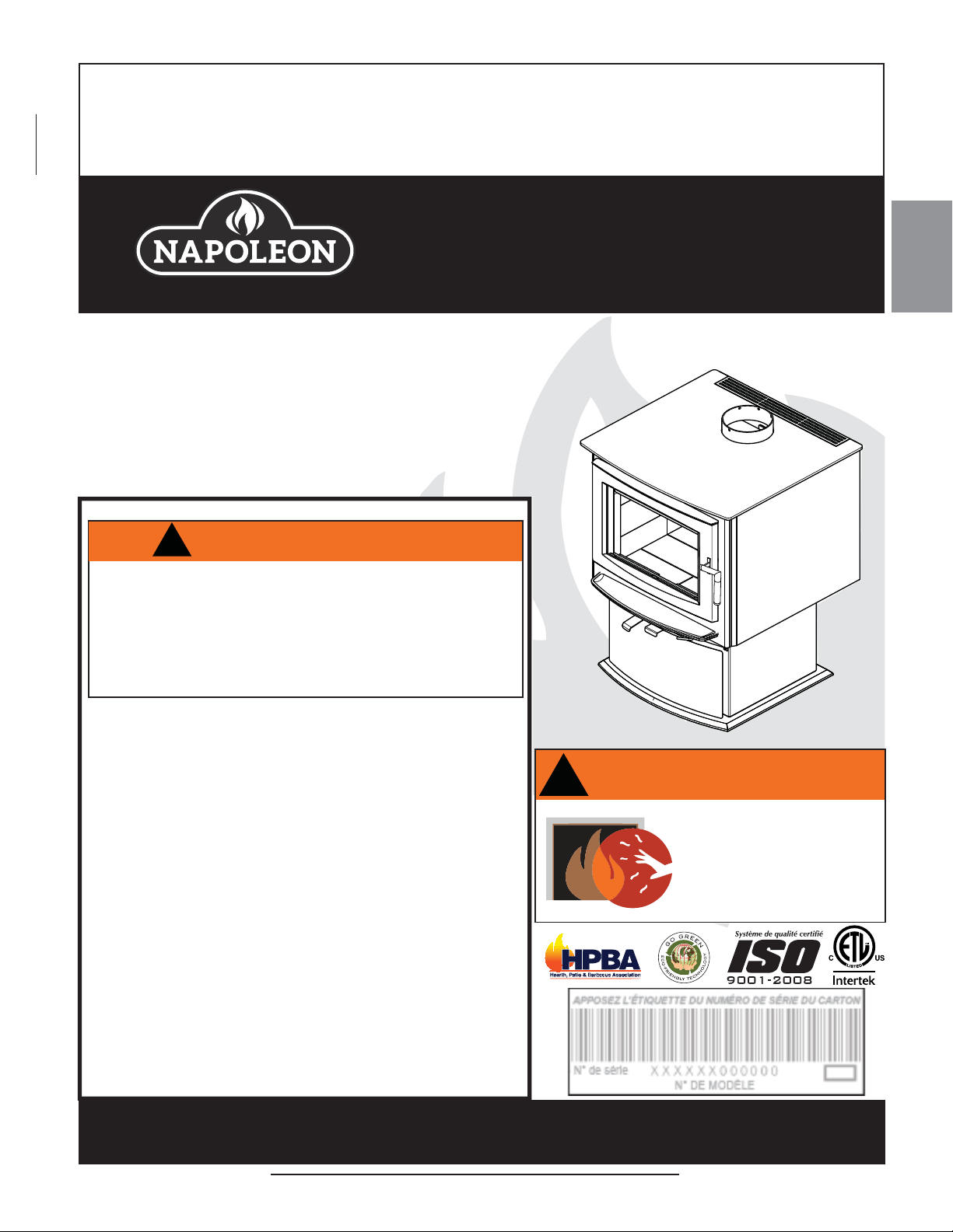
FR
W415-1476 / A / 10.12.16
41
CONSIGNES DE SÉCURITÉ
Si ces instructions ne sont pas suivies à la lettre, un incendie ou une
explosion pourraient s’ensuivre, causant des dommages matériels, des
blessures corporelles ou des pertes de vie. Une installation non conforme, des
ajustements, des altérations, un service ou un entretien inadéquats peuvent
causer des dommages matériels, des blessures corporelles et des pertes de
vie. Veuillez lire le manuel en entier avant d’installer et d’utiliser cet appareil.
Cet appareil n’a pas été testé avec un ensemble de bûches à gaz non
ventilées. Afi n de réduire le risque d’incendie ou de blessure, n’installez
pas d’ensemble de bûches à gaz non ventilées dans cet appareil.
- Cet appareil peut devenir très chaud lorsqu’il fonctionne.
- Les matériaux combustibles, tels que le bois de chauffage, les vêtements mouillés,
etc. placés trop près de l’appareil pourraient prendre feu.
- Il faut empêcher les enfants et les animaux de toucher l’appareil quand il est chaud.
- La cheminée doit être en bon état et ne pas être fêlée. Avant d’installer cet
appareil, contactez le service du bâtiment ou le service d’incendie de votre
municipalité et suivez leurs directives.
- Faites fonctionner l’appareil uniquement avec la porte bien fermée.
- Brûlez le bois en arrière du pare-bûches, directement sur les briques réfractaires.
- N’utilisez pas un chenet et n’essayez pas de surélever le feu de quelque manière.
- Au moins 14 pouces carrés (
90,3
centimètres carrés) d’air extérieur doit être admis
dans la pièce ou directement dans l’appareil par un conduit de 4 pouces (101,6mm)
de diamètre.
- Cet appareil a été conçu pour brûler du bois naturel uniquement. Vous obtenez
une meilleure effi cacité et des émissions plus basses avec du bois dur séché
à l’air qu’avec du bois résineux ou vert, ou du bois dur fraîchement coupé.
- N’allumez pas votre feu à l’aide de produits chimiques ou de liquides tels que
de l’essence, de l’huile à moteur, etc.
-
Cet appareil a été conçu pour brûler du bois naturel uniquement. Ne brûlez pas de
déchets
, des résidus de tonte de pelouse, de caoutchouc, des produits pétroliers
résiduels, de la peinture ou du diluant /
de solvants
, de plastique, des matériaux
contenant de l’amiante, des débris de construction, des traverses de chemin de fer
ou
de bois traités
, du fumier ou des restes d’animaux, du bois de grève imprégné de
sel ou des matériaux salés, du bois non séché,
de charbon
,
de papiers de couleur
,
de
cartons
, des contreplaqués ou des panneaux de particules.
- Ne laissez pas l’appareil chauffer au point où des parties deviennent rougeoyantes.
- GARDEZ LA TEMPÉRATURE SUR LE DESSUS DE L’APPAREIL SOUS
700°F (371°C). Toute tentative de dépasser les débits maximaux de chaleur,
tels que mentionnés dans les spécifi cations de conception, pourrait provoquer
la distorsion de l’acier et causer des dommages.
INSTALLATEUR : LAISSEZ CE MANUEL AVEC L’APPAREIL.
PROPRIÉTAIRE : CONSERVEZ CE MANUEL POUR CONSULTATION ULTÉRIEURE.
NE LAISSEZ PAS LES ENFANTS OU AUTRES INDIVIDUS À RISQUE SEULS À PROXIMITÉ DE L’APPAREIL.
Cet appareil au bois doit faire l’objet d’une inspection et d’un entretien périodiques pour un fonctionnement
adéquat. Les règlements fédéraux de l’États-Unis interdisent d’utiliser cet appareil de chauffage d’une manière
allant à l’encontre des instructions de fonctionnement contenues dans ce manuel.
INSTRUCTIONS
D’INSTALLATION ET
D’OPÉRATION
Wolf Steel Ltd., 24 Napoleon Rd., Barrie, ON, L4M 0G8 Canada /
103 Miller Drive, Crittenden, Kentucky, USA, 41030
Téléphone 705-721-1212 • Télécopieur 705-720-9081 • www.napoleonfoyers.com • [email protected]
10,00 $
LA VITRE CHAUDE CAUSERA
DES BRÛLURES.
NE PAS TOUCHER LA VITRE
AVANT QU’ELLE AIT REFROIDI.
NE JAMAIS LAISSER LES
ENFANTS TOUCHER LA VITRE.
!
AVERTISSEMENT
1.27D
!
AVERTISSEMENT
S1, S4 & S9
MODÈLES SUR PIÉDESTAL
S
4
I
LL
USTRÉ
LE MODÈLE S1, S4 & S9 RESPECTE L’AGENCE DE PROTECTION DE L’ENVIRONNEMENT AMÉRICAINE (E.P.A) 2015 ES LIMITES D’ÉMISSIONS DE BOIS DE
VALEUR STANDARD POUR LES POÊLES À BOIS VENDUS APRÈS LE 15 MAI 2015, 40 C.F. R. SECTION 60. CES APPAREILS ONT ÉTÉ TESTÉS ET HOMOLOGUÉS
PAR INTERTEK TESTING SERVICES SELON LES NORMES: CSA B366.2, ULC S627, UL 1482.

FR
W415-1476 / A / 10.12.16
42
REMARQUE: Les changements autres que de nature éditoriale sont dénotés par une ligne verticale dans la marge.
TABLE DES MATIÈRES
1.0 VUE D’ENSEMBLE DE L’INSTALLATION 43
2.0 INTRODUCTION 44
2.1 DIMENSIONS 45
2.3 SPÉCIFICATIONS 46
2.2 INSTRUCTIONS GÉNÉRALES 46
2.4 INFORMATION GÉNÉRALE 47
2.5 INFORMATION SUR LA PLAQUE D’HOMOLOGATION 48
3.0 PLANIFICATION DE L’INSTALLATION 49
3.1 INSTALLATION DE L’APPAREIL 49
3.2 DÉGAGEMENTS AUX MATÉRIAUX COMBUSTIBLES 49
3.3 PROTECTION DU PLANCHER 50
3.4 AIR EXTÉRIEUR 50
3.4.1 PRISE D’AIR EXTÉRIEUR - MAISON MOBILE 50
3.4.2 MAISON MOBILE 51
4.0 INSTALLATION 51
4.1 CHEMINÉE 52
4.1.1 INSTALLATION DE LA CHEMINÉE 53
4.1.2 AJOUT DE SECTIONS 54
4.1.3 TYPIQUE À TRAVERS LE PLAFOND 55
4.1.4 INSTALLATION TYPIQUE À TRAVERS UN MUR 56
4.1.5 INSTALLATION TYPIQUE DANS UNE CHEMINÉE DE MAÇONNERIE EXISTANTE 57
5.0 FINITIONS 58
5.1 ENLÈVEMENT ET INSTALLATION DE LA PORTE 58
5.2 INSTALLATION DE LA POIGNÉE DE PORTE ET DE LA PORTE 59
5.3 INSTALLATION DES BRIQUES ET DES DÉFLECTEURS EN FIBRE 60
5.4 AJUSTEMENT DU TIROIR À CENDRES 61
6.0 INSTALLATIONS DES ENSEMBLES OPTIONNELLE 62
6.1 INSTALLATION DE L’ ENSEMBLE DU SOUFFLERIE 62
6.1.1 INSTALLATION DE LA SOUFFLERIE 62
7.0 FONCTIONNEMENT 63
7.1 GARNITURE DU PORTE 63
7.2 MÉTHODE POUR ASSURER UNE COMBUSTION OPTIMALE 65
7.3 CONTRÔLE D’AIR 65
7.4 EXTINCTEURS ET DÉTECTEURS DE FUMÉE / MONOXYDE DE CARBONE 65
7.5 COMBUSTIBLE 66
7.6 ALLUMER UN FEU 66
7.6.1 FEU ÉCLAIR 66
7.6.2 FEU CONTINU 67
7.7 ENFUMAGE 67
8.0 ENTRETIEN 67
8.1 ENLÈVEMENT DES CENDRES 68
8.2 FORMATION ET ENLÈVEMENT DE LA CRÉOSOTE 68
8.3 FEU DE CHEMINÉE OU FEU HORS CONTRÔLE 69
8.4 NETTOYAGE DE LA CHEMINÉE 69
8.5 REMPLACEMENT DE LA VITRE 70
8.6 COLLECTEUR D’AIR SECONDAIRE 71
8.7 SOINS DE LA VITRE 72
8.8 SOINS DES PIÈCES PLAQUÉES 72
8.9 BOIS 73
9.0 RECHANGES 74
9.1 VUE D’ENSEMBLE DU S1 75
9.2 S4 OVERVIEW 76
9.3 S9 OVERVIEW 77
9.4 S1, S4 & S9 DOOR ASSEMBLY 78
10.0 S1, S4 & S9 ACCESSORIES 79
11.0 GUIDE DE DÉPANNAGE 80
12.0 GARANTIE 81
13.0 HISTORIQUE D’ENTRETIEN 82
14.0 NOTES 83
NOTE: L’icône du camera indique que les vidéos sont disponibles comme une référence
supplémentaire, visitez http://mynapoleon.napoleonproducts.com/download/index/44/1
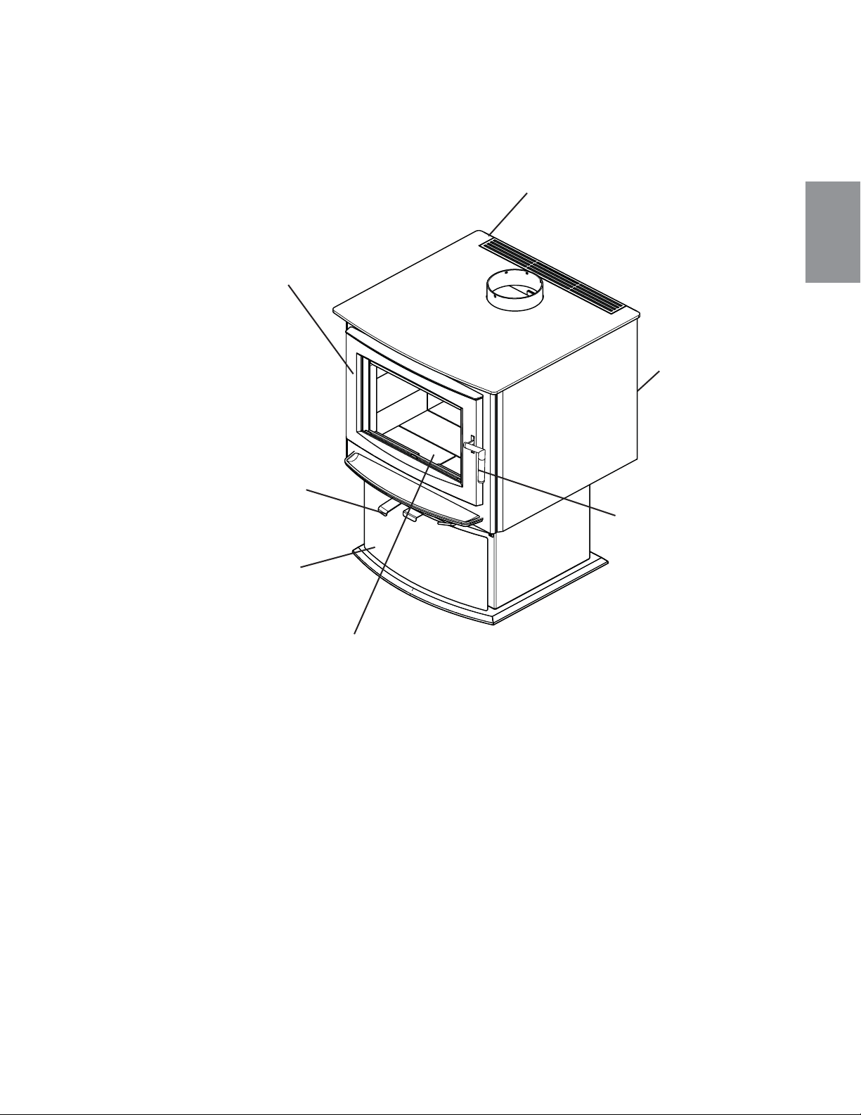
FR
W415-1476 / A / 10.12.16
43
1.0 VUE D’ENSEMBLE DE L’INSTALLATION
S
4
I
L
L
UST
R
É
Plaque d’homologation, voir la
section « INFORMATION SUR LA
PLAQUE D'HOMOLOGATION ».
Soufflerie, voir la
section
«INSTALLATION
DE LA
SOUFFLERIE
OPTIONNEL».
Poignée de porte, voir la
section «INSTALLATION
DE LA PORTE ET DE LA
POIGNÉE DE PORTE».
Briques et déflecteurs, voir la section
« INSTALLATION DES BRIQUES
ET DES DÉFLECTEURS ».
Retour d’air, voir la
section «CONTRÔLE
D’AIR».
Porte, voir les sections
« ENLÈVEMENT ET
INSTALLATION DE
LA PORTE ».
Tiroir à cendres, voir la
section « AJUSTEMENT DU
TIROIR À CENDRES ».

FR
W415-1476 / A / 10.12.16
44
2.0 INTRODUCTION
3.17G
• CET APPAREIL EST CHAUD LORSQU’IL FONCTIONNE ET PEUT CAUSER DE GRAVES BRÛLURES EN CAS DE
CONTACT.
• TOUTE MODIFICATION APPORTÉE À CET APPAREIL OU AUX CONTRÔLES PEUT ÊTRE DANGEREUX ET EST INTERDIT.
• Ne faites pas fonctionner l’appareil avant d’avoir lu et compris les instructions d’opération. Omettre d’utiliser l’appareil selon les
instructions d’opération pourrait causer un incendie ou des blessures.
• Avant d’installer cet appareil, contactez les autorités locales du bâtiment ou le service des incendies et suivez leurs directives.
• Cet appareil doit être installé par un installateur qualifi é.
• Risque de brûlures. L’appareil doit être éteint et refroidi avant d’effectuer un entretien.
• Ne faites pas fonctionner tant que tous les composants ne sont pas complètement installés.
• Ne laissez pas l’appareil chauffer au point où des parties deviennent rougeoyantes.
• N’installez pas de composants endommagés ou incomplets ni des composants substituts.
• Risque de coupures et d’érafl ures. Portez des gants protecteurs et des lunettes de sécurité lors de l’installation. Les bordures des
pièces de métal peuvent être coupantes.
• Les enfants et les adultes devraient être informés des dangers que posent les températures de surface élevées et se tenir à
distance afin d’éviter des brûlures ou que leurs vêtements ne s’enflamment.
• Surveillez attentivement les jeunes enfants lorsqu’ils sont dans la même pièce que l’appareil. Les jeunes enfants et autres sont
plus à risque de contacts accidentels causant des brûlures. Une barrière physique est conseillée lorsque qu’il y a des individus
à risque dans la maison. Pour empêcher l’accès à un appareil ou un poêle, installez une barrière de sécurité pour garder les
jeunes enfants et autres individus à risque hors de la pièce et éloignés des surfaces chaudes. Les vêtements et autres matériaux
combustibles ne doivent pas être posés sur le foyer ou à proximité.
• En raison des températures élevées, le foyer devrait être placé loin des endroits passants et loin des meubles et des rideaux. Les
objets placés devant l’appareil doivent être gardés à une distance d’au moins 48” (1219,2mm) de l’avant de l’appareil.
• Assurez-vous de disposer de mesures de sécurité adéquates pour empêcher les jeunes enfants de toucher aux surfaces chaudes.
• Même une fois que le foyer est éteint, la vitre et/ou le pare-étincelles demeureront chauds pendant un temps prolongé.
• Consultez votre détaillant local de foyer pour connaître les grillages de sécurité et les écrans offerts pour protéger les enfants des
surfaces chaudes. Ces grillages de sécurité et ces écrans doivent être fi xés au plancher.
• Les grillages de sécurité ou écrans enlevés pour faire l’entretien devront être remis en place avant d’utiliser l’appareil.
• Cet appareil ne devra être modifi é en aucun cas.
• Cet appareil ne doit pas être raccordé au conduit d’une cheminée desservant un autre appareil de chauffage à combustible
solide.
• Ne pas opérer l’appareil lorsque la porte vitrée est enlevée, fi ssurée ou brisée. Le remplacement de la vitre devra être effectué
par un technicien de service certifi é ou qualifi é.
• Ne frappez pas et ne claquez pas la porte vitrée de l’appareil.
• Ne faites fonctionner l’appareil qu’avec les portes complètement fermées.
• Seules les portes/façades certifi ées pour cet appareil peuvent être utilisées avec cet appareil.
• Gardez les matériaux d’emballage hors de la portée des enfants et mettez ces matériaux au rebut de façon sécuritaire. Comme tous
les emballages de plastique, ces matériaux ne sont pas des jouets et doivent demeurer hors de la portée des enfants et des bébés.
• Si cet appareil n’est pas installé de façon adéquate, un incendie pourrait s’ensuivre. N’exposez pas l’appareil aux éléments (p. ex.
la pluie, etc.) et gardez-le au sec en tout temps. De l’isolant humide produira une odeur lorsque l’appareil est utilisé.
• La cheminée doit être en bon état et ne pas être fi ssurée. Nettoyez la cheminée au moins deux fois par année et lorsque nécessaire.
• N’allumez pas votre feu à l’aide de produits chimiques ou de liquides tels que de l’essence, de l’huile à moteur, etc.
• Votre appareil nécessite un entretien et un nettoyage périodiques. Négliger cet entretien peut causer des refoulements de fumée
dans la maison.
• Vous obtenez une meilleure effi cacité et des émissions plus basses avec du bois dur séché à l’air qu’avec du bois résineux ou
vert, ou des bois durs fraîchement coupés. Brûler du bois vert ou humide peut causer des accumulations excessives de créosote.
Lorsqu’elle est allumée, cette dernière peut causer un feu de cheminée et un incendie grave pourrait s’ensuivre.
• Cet appareil a été conçu pour brûler du bois naturel uniquement. Ne brûlez pas de déchets
, des résidus de tonte de pelouse,
de caoutchouc, des produits pétroliers résiduels, de la peinture ou du diluant /
de solvants
, de plastique, des matériaux
contenant de l’amiante, des débris de construction, des traverses de chemin de fer ou
de bois traités
, du fumier ou des
restes d’animaux, du bois de grève imprégné de sel ou des matériaux salés, du bois non séché,
de charbon
,
de papiers de
couleur
, emballage-cadeau,
de cartons
, des contreplaqués ou des panneaux de particules. La combustion de ces matériaux
peut entraîner la libération de fumées toxiques ou rendre l’appareil ineffi cace et causer de la fumée.
• Brûlez le bois directement sur les briques réfractaires. N’utilisez pas un chenet et n’essayez pas de surélever le feu de quelque
manière.
• Ne rangez pas de bois à l’intérieur des dégagements prescrits ou à l’intérieur de la zone nécessaire pour procéder au
ravitaillement ou à l’enlèvement des cendres.
• Les cendres doivent être mises dans un contenant métallique avec un couvercle hermétique et déposé sur une surface
incombustible suffi samment éloigné de la maison ou de toute structure jusqu’à ce qu’elles soient complètement refroidies.
• Assurez-vous de respecter les dégagements aux matériaux combustibles lorsque vous installez un manteau ou des tablettes au-
dessus de l’appareil. Les températures élevées sur le mur ou de l’air au-dessus de l’appareil peuvent faire fondre, décolorer ou
endommager les décorations, les téléviseurs ou autres composants électroniques.
• Le cas échéant, le catalyseur doit être installé et en bon état de fonctionnement. Il est recommandé que le catalyseur est
inspecté au moins 3 fois par saison de chauffage.
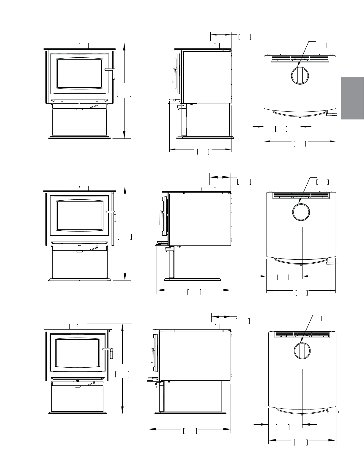
FR
W415-1476 / A / 10.12.16
45
7 1/4"
184mm
22”
559mm
Ø
6 "
152mm
12 3/4"
324mm
25 1/2"
648mm
31 1/4"
793mm
7 3/8"
187mm
26 1/2"
673mm
7 1/4"
184mm
25 1/2"
648mm
12 3/4"
324mm
Ø
6 "
152mm
25 1/2"
648mm
12 3/4"
324mm
Ø
6 "
152mm
34"
864mm
34"
864mm
34"
864mm
S1 ILLUSTRÉ
S4 ILLUSTRÉ
S9 ILLUSTRÉ
2.1 DIMENSIONS
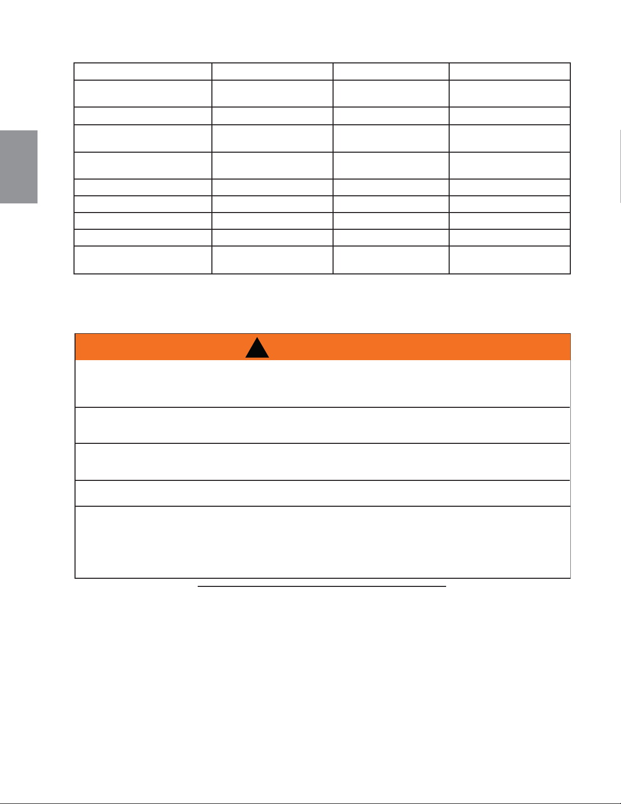
FR
W415-1476 / A / 10.12.16
46
2.2 INSTRUCTIONS GÉNÉRALES
4.7
CET APPAREIL DOIT ÊTRE RACCORDÉ ÉLECTRIQUEMENT PAR UN ÉLECTRICIEN QUALIFIÉ
CONFORMÉMENT AUX CODES LOCAUX. EN L’ABSENCE DE CODES LOCAUX, UTILISEZ LA VERSION
COURANTE DU CODE CANADIEN DE L'ÉLECTRICITÉ CSA C22.1 (AU CANADA) OU LE NATIONAL
ELECTRICAL CODE ANSI/NFPA 70 AUX ÉTATS-UNIS.
CET APPAREIL N’A PAS ÉTÉ TESTÉ AVEC UN ENSEMBLE DE BÛCHES À GAZ VENTILÉES OU NON
VENTILÉES. AFIN DE RÉDUIRE LE RISQUE D’INCENDIE OU DE BLESSURE, N’INSTALLEZ PAS
D’ENSEMBLE DE BÛCHES À GAZ VENTILÉES OU NON VENTILÉES DANS CET APPAREIL.
FAIRE FONCTIONNER VOTRE APPAREIL AVEC LA CHUTE À CENDRES OUVERTE OU ENTROUVERTE
CONSTITUE UN RISQUE D’INCENDIE QUI PEUT CAUSER UNE DÉCOLORATION DE LA PORTE
PLAQUÉE OR, DES DOMMAGES INTERNES À L’APPAREIL OU UN FEU DE CHEMINÉE.
CET APPAREIL NE DOIT PAS ÊTRE RACCORDÉ AU CONDUIT D’UNE CHEMINÉE DESSERVANT UN
AUTRE APPAREIL.
CET APPAREIL ET SES COMPOSANTS SONT CONÇUS POUR ÊTRE INSTALLÉS ET FONCTIONNER
COMME UN SYSTÈME. TOUTE MODIFICATION OU SUBSTITUTION DE COMPOSANTS AUTRES QUE
CELLES INDIQUÉES DANS LES INSTRUCTIONS D'INSTALLATION AURONT POUR EFFET D'ANNULER
L'HOMOLOGATION ET RISQUE D'ANNULER LA GARANTIE. CELA PEUT AUSSI CRÉER UNE
INSTALLATION DANGEREUSE. LISEZ BIEN TOUTES LES INSTRUCTIONS AVANT DE COMMENCER
VOTRE INSTALLATION ET SUIVEZ-LES À LA LETTRE.
!
AVERTISSEMENT
• Avant d’installer cet appareil, contactez les autorités locales en bâtiment ou le service des incendies et votre
compagnie d’assurance afi n de vous conformer à leurs directives.
• De la fumée non toxique émanera de l’appareil lors du processus de cuisson de la peinture. Ouvrez une fenêtre
à proximité de l’appareil pour aider à dissiper la fumée.
• Enlevez la poussière ou les débris sur le dessus de l’appareil avant de l’allumer car la peinture ramolirra
pendant que l’appareil se réchauffe et durcira pendant le processus de cuisson. Pour cuire la peinture, faites
brûler l’appareil à feu modéré durant les quelques premiers allumages.
• Pour empêcher le joint d’étanchéité de coller à l’appareil lors de la cuisson de la peinture, ouvrez la porte de
l’appareil toutes les 5-10 minutes.
• Durant les deux premières semaines, faites brûler l’appareil avec beaucoup de bois et ouvrez le contrôle de
combustion au maximum pendant une heure pour permettre à l’appareil d’éliminer toute humidité dans l’acier
et les briques réfractaires. La production de chaleur initiale sera réduite alors que l’humidité est chassée
de l’appareil. Il sera nécessaire de faire plusieurs feux chauds pour éliminer cette humidité. LORS DE CE
PROCESSUS, NE SURCHAUFFEZ PAS L’APPAREIL. RÉDUISEZ L’APPORT D’AIR À L’APPAREIL SI
CELUI-CI OU LA CHEMINÉE DEVIENNENT ROUGEOYANTS.
* Comme testé en utilisant la méthode de test 28
** Ces données peuvent varier considérablement selon les conditions particulières.
*** BTU/hr réalistes estimés par Wolf Steel ltée avec des bûches de bois dur et un ravitaillement normal.
2.3 SPÉCIFICATIONS
SPÉCIFICATIONS S1 S4 S9
CHAMBRE DU FOYER 13 1/2”x18”x12”
(34.3cmx45.7cmx30.5cm)
18”x18”x12”
(45.7cmx45.7cmx30.5cm)
22 1/2”x18”x12”
(57.2cmx45.7cmx30.5cm)
CAPACITÉ 1.7 ft
3
(0.05m
3
) 2.25 ft
3
(0.06m
3
) 3.0 ft
3
(0.09m
3
)
SURFACE CHAUFFÉE
APPROX.**
600-1500 ft
2
(56-139m
2
)
1000-2000 ft
2
(93-186m
2
)
1000-3500 ft
2
(93-325m
2
)
DÉBIT DE CHALEUR
MAXIMALE***
55,000 BTU/ Hr 70,000 BTU/ Hr 85,000 BTU/ Hr
DÉBIT DE CHALEUR* 11,700 - 42,200 BTU/ Hr 11,400 - 41,300 BTU/ Hr 11,800 - 34,000 BTU/ Hr
DURÉE COMBUSTION LENTE* 7 Heurs 9 Heurs 12 Heurs
POIDS SANS BRIQUES 215 lbs (98kg) 250 lbs (113.4kg) 285 lbs (129kg)
POIDS DES BRIQUES 110 lbs (50kg) 145 lbs (65.8kg) 114 lbs (52kg)
LONGUEUR IDÉALE DES
BÛCHES
12” (30.5cm) 16” (40.6cm) 21” (53.3cm)
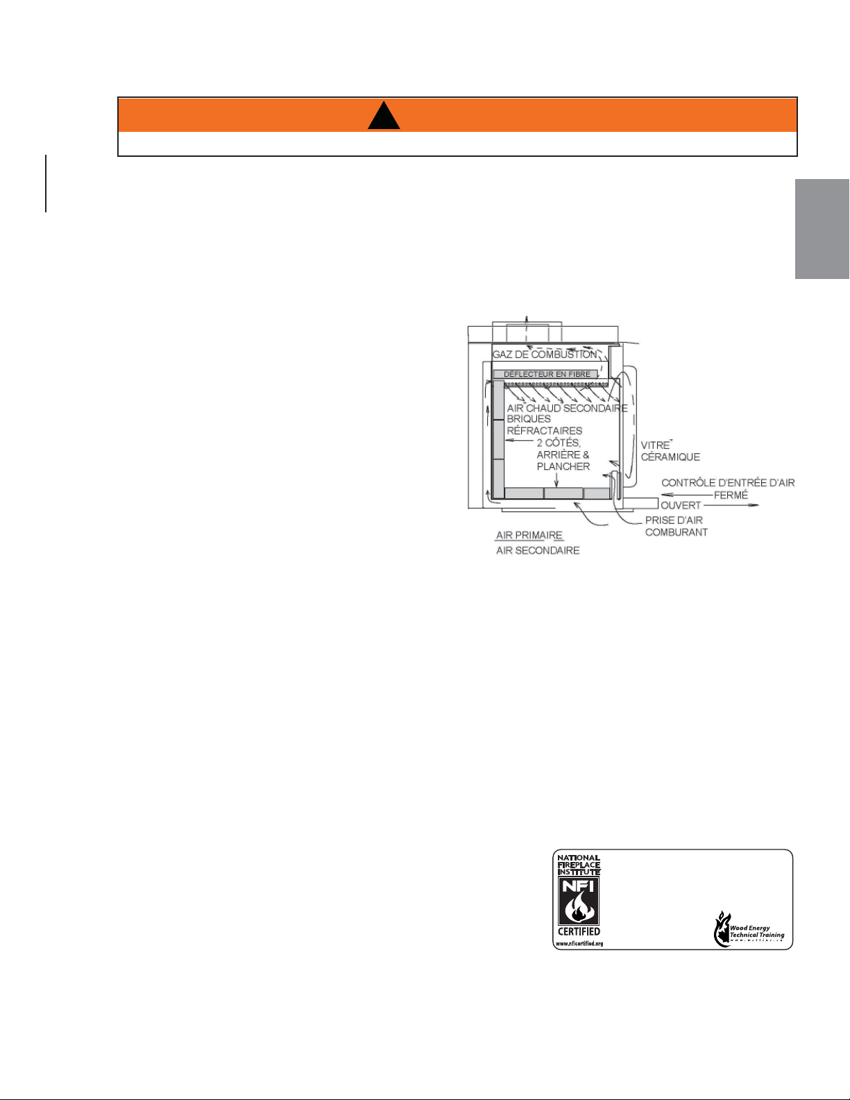
FR
W415-1476 / A / 10.12.16
47
2.4 INFORMATION GÉNÉRALE
NE PAS UTILISER CET APPAREIL SANS QUE LE PIÉDESTAL SOIT INSTALLÉ.
!
AVERTISSEMENT
Votre appareil a été conçu afi n de répondre spécifi quement aux exigences des normes d’émissions de particules
de l’E.P.A. américaine de 2015 et a subi un nombre considérable de tests dans des laboratoires canadiens et
américains. Ce système est le plus effi cace, le plus simple et sans problème connu; il fonctionne comme suit:
Pour favoriser la circulation adéquate des produits d’échappement, le système d’évacuation de la cheminée de
l’appareil au bois doit être conçu de façon à minimiser les déviations. Les systèmes d’évacuation trop courts
ou trop longs peuvent nuire à la circulation des produits d’échappement. L’appareil au bois et le système
d’évacuation de la cheminée doivent bénéfi cier d’un apport d’air comburant suffi sant, non seulement pour
alimenter la fl amme dans la chambre de combustion, mais aussi pour favoriser un tirage adéquat. Un bon équilibre
entre l’air comburant et le système d’évacuation de la cheminée optimisera la performance de votre appareil.
L’air comburant entre par deux ouvertures dans le
plancher de l’appareil qui peuvent être ajustées par un
contrôle de combustion. L’air pénètre par l’ouverture
avant et s’engage de chaque côté de la porte pour
rejoindre un collecteur de préréchauffement installé au
sommet de la chambre de combustion. L’air descend
ensuite le long de la vitre pour alimenter le feu et aussi
assurer que la vitre demeure propre. L’air provenant
de cette ouverture pénètre aussi directement dans
la chambre de combustion au niveau de l’âtre. L’air
secondaire pénètre par l’ouverture arrière, monte
par l’arrière le long du tube d’air secondaire jusqu’au
collecteur installé au sommet où l’air est propulsé
latéralement pour oxyder les gaz sous la sortie de fumée.
La chambre de combustion est revêtue de briques réfractaires à haute température sur deux côtés, l’arrière
et le plancher. Le plafond est revêtu de défl ecteurs en fi bre afi n de maintenir une température élevée dans la
chambre de combustion. Ainsi, les gaz qui se mélangent à l’air préréchauffé dans le tuyau d’air secondaire
s’allument et brûlent facilement. Les côtés et l’arrière de l’appareil sont munis d’une deuxième paroi de façon
à diriger la chaleur vers le haut et vers l’avant dans la pièce.
Assurez-vous qu’il y ait suffi samment d’air comburant. Dans la maison, beaucoup d’appareils doivent
se partager l’air disponible, tels : les hottes de cuisinière, les systèmes de chauffage à air pulsé ou les
ventilateurs de salle de bain.
Les bruits causés par l’expansion et la contraction lors des cycles de chauffage et de refroidissement sont
tout à fait normaux et il faut s’y attendre.
Après de longues périodes sans utiliser l’appareil, telles qu’à la suite de vacances ou à la fi n de l’été, il
se peut qu’une légère odeur se dégage pendant quelques heures. Ceci est causé par des particules de
poussière brûlant sur la chambre de combustion. Ouvrez une fenêtre afi n d’aérer la pièce de manière
suffi sante.
AVERTISSEMENT - PROPOSITION 65 DE LA CALIFORNIE:
L’utilisation de cet appareil peut produire de la fumée qui contient
des substances chimiques qui, selon l’État de Californie, causeraient
le cancer, des malformations congénitales ou autres dangers pour la
reproduction.
Si vous achetez le tiroir à cendres optionnel, assurez-vous que la
chute à cendres est complètement fermée et que la porte se ferme
avec un bruit sec, délogeant ainsi tout ce qui pourrait être coincé
dans l’ouverture (cendres, morceaux de charbon).
Si vous utilisez la prise d’air extérieur de votre appareil, vous ne devriez jamais manquer d’air comburant. Si
vous choisissez de ne pas utiliser cette prise d’air extérieur et que vous avez des problèmes de tirage ou de
fumée, vous devrez ouvrir une fenêtre ou trouver une autre façon de fournir de l’air comburant à l’appareil.
Nous suggérons que nos poêles à bois
soient installés et entretenus par des
professionnels certifiés aux États-Unis par
le National Fireplace Institute® (NFI) et au
Canada par le Wood
Energy Technical
Training (WETT).
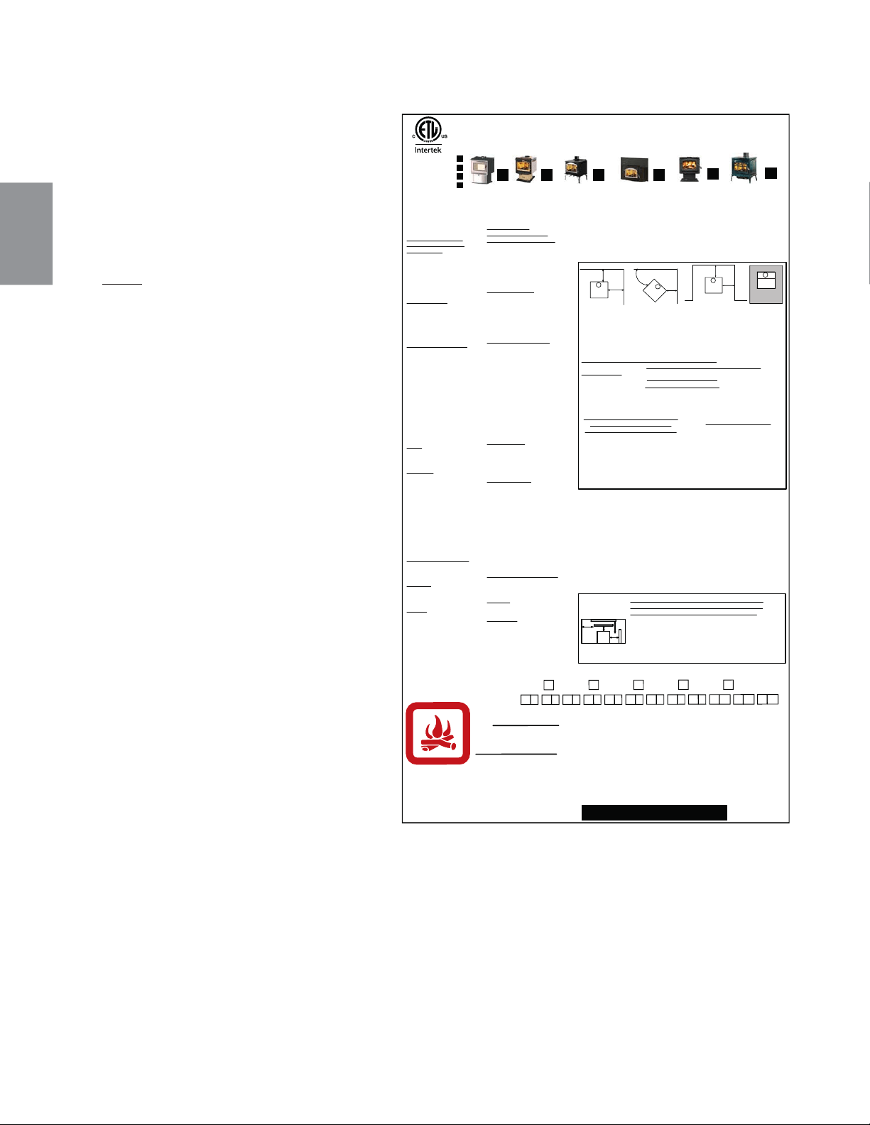
FR
W415-1476 / A / 10.12.16
48
2.5 INFORMATION SUR LA PLAQUE D’HOMOLOGATION
Pour l’emplacement de la plaque
d’homologation, voir la section «VUE
D’ENSEMBLE DE L’INSTALLATION».
Cette illustration est à titre de
référence seulement. Consultez la
plaque d’homologation pour obtenir
l’information précise.
NOTE: NOTE: Le plaque
d’homologation doit rester avec
l’appareil à tout temps. Il ne doit
pas être enlevé.
ÉCHANTILLON
PLAQUE D’HOMOLOGATION DU POÊLE ILLUSTRÉE (1400).
LISTED SOLID FUEL BURNING FIREPLACE INSERT /
ENCASTRÉ À COMBUSTIBLE SOLIDE HOMOLOGUÉ
TESTED TO / TESTÉ SELON :
ULC S628 / UL 1482
FROM HEATER / DU POÊLE
RESIDENTIAL / RÉSIDENTIEL
S4
16IN/PO (406 mm)
12IN/PO (305 mm)
6IN/PO (152 mm)
USING DOUBLE WALL CONNECTOR /
UTILISATION D’UN CONDUIT DE
RACCORDEMENT À DOUBLE PAROI
MAISON / MOBILE HOME*
S4
1400
16IN/PO (406 mm)
10IN/PO (254 mm)
6IN/PO (152 mm)
6IN/PO (152 mm)
4IN/PO (102 mm)
4IN/PO (102 mm)
EPI 1402
INSTALL AND USE ONLY IN
ACCORDANCE WITH THE
MANUFACTURER’S
INSTRUCTIONS AND LOCAL
BUILDING CODES.
MINIMUM CEILING HEIGHT:
7FT (2.13m)
HEARTH EXTENSION /
COMBUSTIBLE FLOOR
PROTECTION: IF INSTALLED
ON A COMBUSTIBLE FLOOR,
UNIT MUST BE PLACED ON A
NON-COMBUSTIBLE FLOOR
PROTECTOR EXTENDING 18”
(455mm) IN FRONT AND 8”
(205mm) TO THE SIDES AND
BACK.
CHIMNEY TYPE: MINIMUM 6”
(152mm) DIAMETER
APPROVED RESIDENTIAL
TYPE FOR MOBILE HOME USE
A CHIMNEY LISTED TO ULC
S629 IN CANADA OR UL 103HT
IN THE USA.
CHIMNEY CONNECTOR: 6”
(152mm) DIAMETER MINIMUM
24 GAUGE STEEL MINIMUM
CLEARANCE FROM
HORIZONTAL CONNECTOR
AND CEILING 18” (455mm).
DO NOT OBSTRUCT SPACE
UNDER HEATER.
SPECIAL METHODS ARE
REQUIRED WHEN PASSING A
CHIMNEY THROUGH A WALL
OR CEILING. SEE INSTRUC-
TIONS AND BUILDING CODES.
DO NOT CONNECT THIS UNIT
TO A CHIMNEY FLUE SERVING
ANOTHER APPLIANCE.
FUEL: FOR USE WITH WOOD
ONLY. DO NOT USE GRATE OR
ELEVATE FIRE. BUILD WOOD
FIRE DIRECTLY ON HEARTH.
WARNING: RISK OF SMOKE
SPILLAGE. OPERATE ONLY
WITH DOOR FULLY CLOSED.
REPLACE GLASS ONLY WITH
CERAMIC GLASS.
DO NOT OVERFIRE. IF
HEATER OR CHIMNEY
CONNECTORS GLOW, YOU
ARE OVERFIRING. INSPECT
AND CLEAN CHIMNEY
FREQUENTLY. UNDER
CERTAIN CONDITIONS OF
USE CREOSOTE BUILD-UP
MAY OCCUR RAPIDLY.
OPTIONAL BLOWER KIT:
EP-62, 115V, 60HZ, 0.82AMP.
ROUTE CORD AWAY FROM
UNIT.
DANGER: RISK OF
ELECTRICAL SHOCK.
DISCONNECT POWER
BEFORE SERVICING UNIT.
INSERT: INSTALL AND USE
ONLY IN SOLID FUEL
BURNING FIREPLACES. DO
NOT REMOVE BRICKS OR
MORTAR FROM SOLID FUEL
BURNING FIREPLACE.
INSTALL WITH A POSITIVE
FLUE CONNECTOR AND
FACEPLATE.
POUR INSTALLATION ET
UTILISATION CONFORM
ÉMENT AUX
INSTRUCTIONS DU FABRICANT ET
AUX CODES LOCAUX DU BÂTIMENT.
HAUTEUR DE PLAFOND MINIMAL
7PI (2,13m).
PROLONGEMENT
D’ÂTRE/PROTECTION DU
PLANCHER COMBUSTIBLE: SI
INSTALL
É SUR UN PLANCHER
COMBUSTIBLE, L’APPAREIL DOIT
ÊTRE PLAC
É SUR UNE PLAQUE
PROTECTRICE INCOMBUSTIBLE
S’ÉTENDANT SUR 18” (455mm)
À
L’AVANT ET 8” (205mm) À L’ARRIÈRE
ET SUR LES CÔTÉS.
TYPE DE CHIMNÉE: DIAMÈTRE
MINIMAL DE 6” (152mm)
APPROUVÉE POUR USAGE
RÉSIDENTIEL. MAISON MOBILE
EMPLOYEZ UNE CHEMINÉE
HOMOLOGUÉE ULC S629 AU
CANADA OU UL 103HT AUX
ÉTATS-UNIS.
RACCORD DE CHEMINÉE:
DIAMÈTRE DE 6” (152mm) D’ACIER
DE CALIBRE 24 MINIMUM. 18”
(455mm) DE DÉGAGEMENT MINIMAL
ENTRE LE RACCORD HORIZONTAL
ET LE PLAFOND.
NE RIEN ENTREPOSER SOUS
L’APPAREIL.
DES MÉTHODES SPÉCIALES SONT
REQUISES LORSQU’UNE CHEMINÉE
TRAVERSE UN MUR OU UN
PLAFOND. VOIR LES INSTRUC-
TIONS ET LES CODES DU
BÂTIMENT.
NE PAS RACCORDER À LA
CHEMINÉE D’UN AUTRE APPAREIL.
COMBUSTIBLE: POUR USAGE AVEC
LE BOIS SEULEMENT. N’UTILISEZ
PAS DE CHENET OU NE
SURÉLEVEZ PAS LE BOIS.
PRÉPAREZ LE FEU DIRECTEMENT
SUR L’ÂTRE.
AVERTISSEMENT: RISQUE
D’ÉCHAPPEMENT DE FUMÉE. TENIR
LA PORTE FERMÉE LORSQUE LE
POÊLE FONCTIONNE. REMPLACEZ
LA VITRE PAR UNE VITRE EN
CÉRAMIQUE SEULEMENT.
NE SURCHAUFFEZ PAS L’APPAREIL.
SI L’APPAREIL OU LES RACCORDS
ROUGEOIENT, L’APPAREIL
SURCHAUFEE. INSPECTEZ ET
NETTOYEZ LA CHEMINÉE
FRÉQUEMMENT. DANS CERTAINES
CONDITIONS, DES DÉPÔTS DE
CRÉOSOTE PEUVENT SE FORMER
RAPIDEMENT.
SOUFFLERIE OPTIONNELLE: EP-62,
115V, 60HZ, 0,82A. TENEZ LE
CORDON ÉLECTRIQUE LOIN DE
L’APPAREIL.
DANGER: RISQUE DE SECOUSSE
ÉLECTRIQUE. DÉBRANCHEZ AVANT
DE PROCÉDER À L’ENTRETIEN.
ENCASTRÉ: INSTALLEZ ET UTILISEZ
SEULEMENT DANS UN FOYER À
COMBUSTIBLE SOLIDE. NE RETIREZ
PAS DE MORTIER, NI BRIQUES DU
FOYER À COMBUSTIBLE SOLIDE.
INSTALLEZ AVEC UNE GAINE
CONFORME ET UNE PLAQUE DE
RECOUVREMENT.
CONTACT LOCAL BUILDING FIRE OFFICIALS ABOUT RESTRICTIONS AND
INSTALLATION INSPECTION IN YOUR AREA. MODEL 1400 IS SUITABLE FOR USE
IN MOBILE HOMES WHEN USED WITH OUTSIDE AIR INSTALLATION KIT (111KT).
A MINIMUM CLEARANCE OF 18” (457mm) TO THE CHIMNEY CONNECTOR MAY
BE REQUIRED BY THE AUTHORITY HAVING JURISDICTION.
RENSEIGNEZ-VOUS AUPR
ÈS DES AUTORITÉS LOCALES DU BÂTIMENT ET DU
SERVICE DES INCENDIES AU SUJET DES RESTRICTIONS ET DES INSPECTIONS
D’INSTALLATION DANS VOTRE RÉGION. LES MODÈLES 1400 PEUVENT ÊTRE
INSTALLÉS DANS UNE MAISON MOBILE SI INSTALLÉS CONJOINTEMENT AVEC UNE
PRISE D’AIR EXTÉRIEUR (111KT). UN DÉGAGEMENT MINIMAL DE 18” (457mm)
JUSQU’AU RACCORD DE LA CHEMINÉE PEUT ÊTRE EXIGÉ PAR L’AUTORITÉ AYANT
JURIDICTION.
8"
8"
18"
8"
ALCOVE
A"
B"
C
BACK WALL (M/A)
45°
SIDE WALL (M/L)
BACK WALL (M/A)
SIDE WALL (M/L)
B
A
IF THE STOVE IS TO BE INSTALLED ON A COMBUSTIBLE FLOOR, IT MUST BE
PLACED ON AN APPROVED NON-COMBUSTIBLE HEARTH PAD, THAT
EXTENDS 8” (200mm) BEYOND THE STOVE SIDES AND BACK, AND 18”
(455mm) TO THE FRONT.
SI LE PO
Ê
LE EST INSTALL
É SUR UN PLANCHER COMBUSTIBLE, IL DOIT ÊTRE PLACÉ
SUR UNE BASE DE PROTECTION INCOMBUSTIBLE CERTIFÉE QUI DOIT DÉPASSER
LES CÔTÉS ET L’AMÉRE DU
PO
Ê
LE DE 8” (200mm) ET SE PROLONGER DE 18”
(455mm) SUR LE DEVANT.
MINIMUM CLEARANCE TO COMBUSTIBLE MATERIAL WITH SINGLE WALL
CHIMNEY CONNECTOR / D
ÉGAGEMENTS MINIMAUX AUX MATÉRIAUX
COMBUSTIBLES AVEC RACCORD DE CHEMINÉE À PAROI SIMPLE:
*
MODELS 1400 AND S4 MAY BE INSTALLED INTO A MOBILE HOME IN THE
UNITED STATES ONLY.
*
LE MODÈLES 1400 ET S4 NE PEUT ÊTRE INSTALLÉ QUE DANS UNE MAISON
MOBILE AUX ÉTATS-UNIS SEULEMENT.
HOT WHILE IN OPERATION. DO NOT TOUCH. KEEP CHILDREN,
CLOTHING AND FURNITURE AWAY. CONTACT MAY CAUSE
SKIN BURNS.
QUAND L’APPAREIL FONCTIONNE, LA SURFACE DEVIENT
CHAUDE. NE PAS TOUCHER. TENIR LES ENFANTS, LES
VÊTEMENTS ET LES MEUBLES À L’ÉCART. LE CONTACT PEUT
CAUSER DES BRÛLURES À LA PEAU.
CAUTION:
ATTENTION:
W385-2031 / A
EPA1400
1400 1400L 1402
1450
S4
WOLF STEEL LTD.
24 NAPOLEON ROAD, BARRIE, ON, L4M 0G8 CANADA
1400C
9700539 (WSL)
4001657 (NGZ)
4001658 (NAC)
4001659 (WUSA)
LISTED SOLID FUEL BURNING SPACE HEATER / POÊLE À COMBUSTIBLE SOLIDE
HOMOLOGUÉ TESTED TO: / TESTÉ SELON : UL1482 / ULC S627
MODEL / MODÈLE - EPA 1400
U.S. ENVIRONMENTAL PROTECTION AGENCY
U
.
S
.E
N
V
IRO
N
MEN
T
AL P
ROTEC
T
I
O
N
AGENCY
Certified to comply with 2015 particulate emissions standards. Not approved for sale
C
e
rtified to c
o
m
plywith 2015
parti
c
ul
ate emis
sio
ns s
tandards
.
N
o
tappr
ov
ed for sale
after May 15, 2020. Certifié conforme à la norme d’ émanation de particles de 2020. Non approuvé pour la vente après le 15 mai, 2020.
after May
15
,
2
02
0. Certi
fiéc
o
nfor
m
eàlan
orm
e
d’ é
m
a
na
ti
on dep
arti
cle
s
de 202
0. Non appro
uv
ép
our
l
a
v
en
t
e
après le15mai,2020.
40 CFR Part 60,Subpart AAA.
40
CF
R
P
art 60,Sub
part
A
A
A
.
1400
12IN/PO (305 mm)
12IN/PO (305 mm)
6IN/PO (152 mm)
1400
10IN/PO (254 mm)
6IN/PO (152 mm)
4IN/PO (102 mm)
S4
16IN/PO (406 mm)
6IN/PO (152 mm)
4IN/PO (102mm)
CEILING / PLAFOND
C
D
B
A
FLOOR / PLANCHER
CLEARANCES TO COMBUSTIBLE CONSTRUCTION /
D
ÉGAGEMENTS AUX MATÉRIAUX COMBUSTIBLES:
(MEASURED TO UNIT / À PARTIR DE L’APPAREIL)
A SIDE FACING / CÔTÉ 1 IN/PO (25mm)
*
B TOP FACING / DESSUS 28 IN/PO (710mm)
C MANTEL / TABLETTE 28 IN/PO (710mm)
D SIDE WALL / MUR LATÉRAL 17 IN/PO (430mm)
*
CLEARANCE TO EDGE OF FLASHING / DÉGAGEMENT AU
BORD DE LA FAÇADE
3.5 Grams Per Hour / 2015 Crib Wood / 3.5 Grammes par heure / Crib Wood 2015
3.
5Gr
a
ms
P
er
H
our / 2015 Cr
i
bW
ood / 3.5 G
r
a
m
me
s
pa
r
he
ure / Crib Wood 201
5
MANUFACTURE DATE: / DATE DE FABRICATION:
YEAR:
2016
2017
2018
MONTH:
2019
2020
24365871091211
1
THIS WOOD APPLIANCE NEEDS PERIODIC INSPECTION AND REPAIR FOR
PROPER OPERATION. CONSULT THE OWNER'S MANUAL FOR FURTHER
INFORMATION. IT IS AGAINST UNITED STATES FEDERAL REGULATIONS TO
OPERATE THIS WOOD APPLIANCE IN A MANNER INCONSISTENT WITH THE
OPERATING INSTRUCTIONS IN THE OWNER'S MANUAL.
CET APPAREIL AU BOIS DOIT FAIRE L'OBJECT D'UNE INSPECTION ET D'UN
ENTRETIEN PÉRIODIQUES POUR UN FONCTIONNEMENT ADÉQUAT. CONSULTEZ
LE MANUEL D'INSTRUCTIONS POUR PLUS D'INFORMATION. LES RÈGLEMENTS
FÉDÉRAUX DE L'ÉTATS-UNIS INTERDISENT D'UTILISER CET APPAREIL DE
CHAUFFAGE D'UNE MANIÈRE ALLANT À L'ENCONTRE DES INSTRUCTIONS DE
FONCTIONNEMENT CONTENUES DANS CE MANUEL.
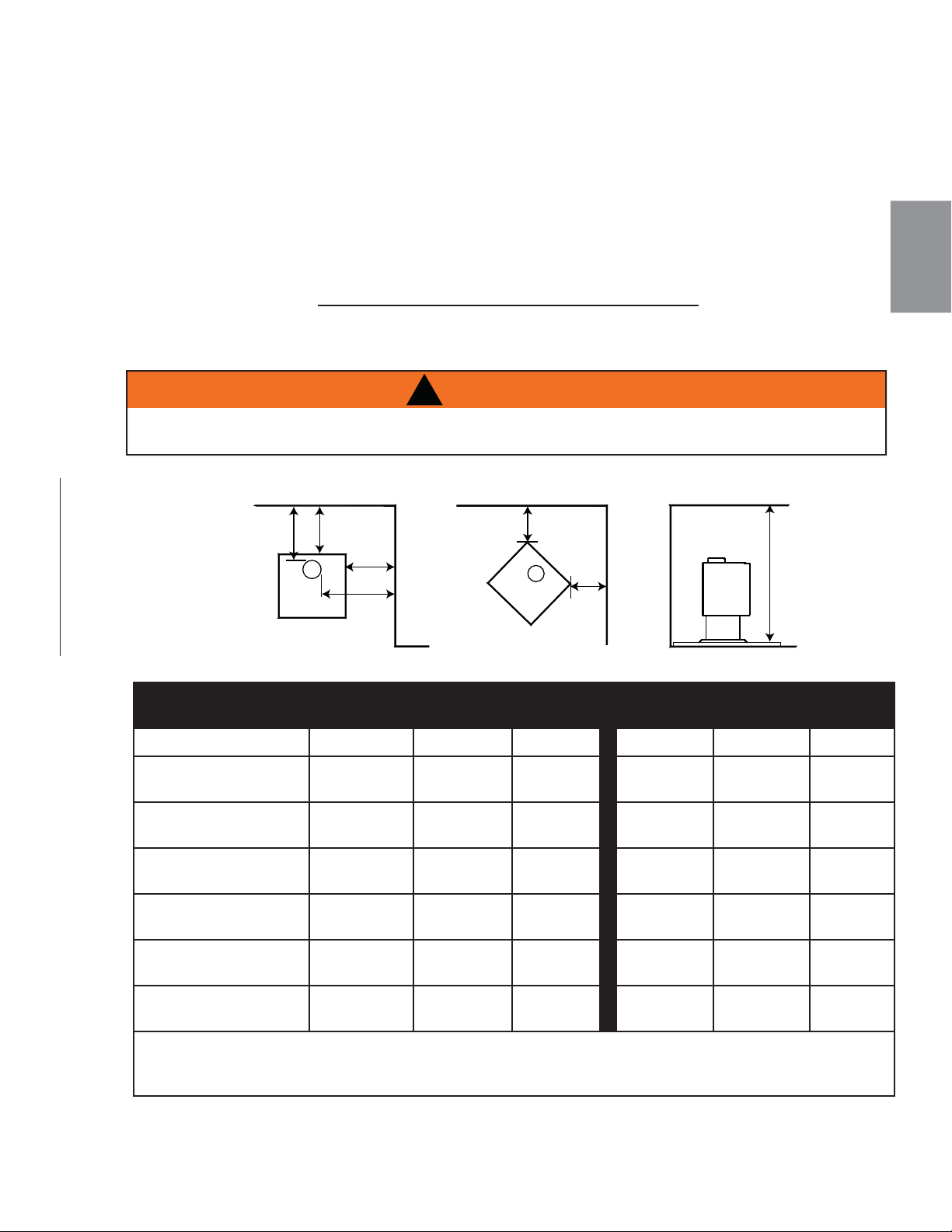
FR
W415-1476 / A / 10.12.16
49
Faites installer votre poêle par un détaillant autorisé. Si vous l’installez vous-même, faites vérifi er vos plans
d’installation et/ou l’installation par votre détaillant.
Élaborez un plan détaillé de l’installation en y incluant les dimensions puis vérifi ez les dimensions avec les
exigences énoncées dans ce manuel.
Pour les enceintes d’encastré, lorsque vous déterminez l’emplacement du poêle, localisez les montants du
mur (pour des évacuations horizontales). Vous devrez possiblement ajuster la position du poêle afi n que
l’évent ne passe pas au même niveau qu’une pièce de charpente. Le poêle doit être positionné de façon à ce
qu’aucun article combustible soit placé, ou puisse pivoter (p. ex. rideaux, portes) à moins de 48” (1219,2mm)
de la face vitrée du poêle.
67.1B
3.0 PLANIFICATION DE L’INSTALLATION
3.1 INSTALLATION DE L’APPAREIL
3.2 DÉGAGEMENTS AUX MATÉRIAUX COMBUSTIBLES
PARALLÈLE ET EN
COIN
CONDUIT DE RACCORDEMENT À
PAROI SIMPLE
CONDUIT DE RACCORDEMENT À
PAROI DOUBLE
S1 S4 S9 S1 S4 S9
MUR DE CÔTÉ (A) 16”
(40.6cm)
16”
(40.6cm)
22”
(55.9cm)
16”
(40.6cm)
16”
(40.6cm)
22”
(55.9cm)
MUR DE CÔTÉ À LA
BUSE (B)
21”
(53.3cm)
21”
(53.3cm)
21”
(53.3cm)
19”
(48.3cm)
19”
(48.3cm)
19”
(48.3cm)
MUR ARRIÈRE (C) 10”
(254mm)
12”
(305mm)
12”
(305mm)
6”
(152mm)
6”
(152mm)
12”
(305mm)
MUR ARRIÈRE À LA
BUSE (D)
13”
(33cm)
16.5”
(41.9cm)
16.5”
(41.9cm)
9”
(229mm)
9”
(229mm)
16.5”
(41.9cm)
COIN (E) 6”
(152mm)
6”
(152mm)
8”
(203mm)
2”
(51mm)
4”
(102mm)
8”
(203mm)
PLAFOND (F) 7 pieds
(2.1m)
7 pieds
(2.1m)
7 pieds
(2.1m)
7 pieds
(2.1m)
7 pieds
(2.1m)
7 pieds
(2.1m)
Tous les dégagements peuvent être réduits lorsqu’une protection acceptable par les autorités locales est
utilisée. Les installations avec des dégagements réduits doivent se conformer aux normes NFPA211 ou
CAN/CSA-B365.
NE L’INSTALLEZ PAS DANS UN ESPACE AYANT MOINS DE 7 PIEDS DE HAUTEUR (DU PLAFOND AU
BAS DE L’APPAREIL, EXCLUANT LA HAUTEUR DE LA BASE DE PROTECTION).
!
AVERTISSEMENT
MUR DE L’ARRIÈRE
B
MUR DU CÔTÉ
A
C
MUR DU CÔTÉ
F
D
E
E
MUR DE L’ARRIÈRE
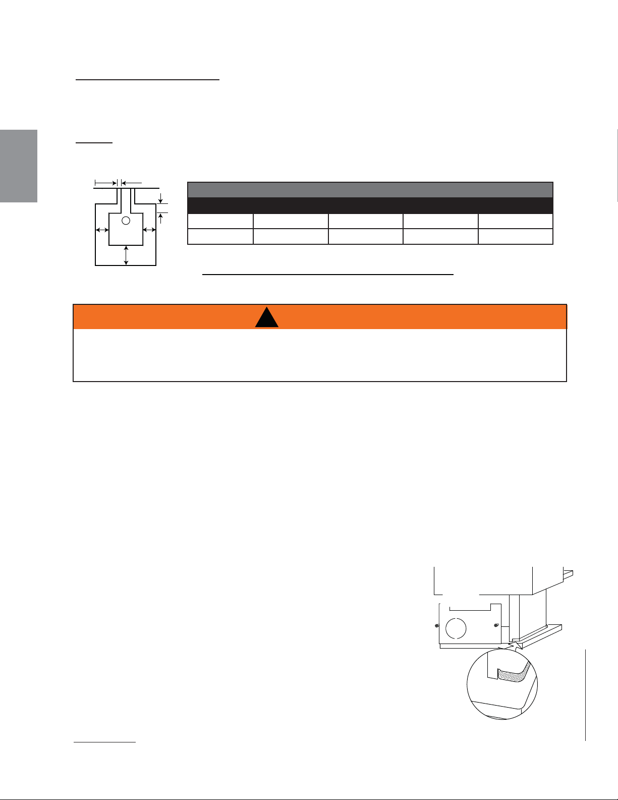
FR
W415-1476 / A / 10.12.16
50
99.1B
PROTECTEUR DES BRAISES:
L’appareil doit être installé sur un protecteur thermique incombustible se prolongeant sur le devant, les côtés et
l’arrière de l’appareil selon les exigences minimales ci-dessous.
NOTE : Une protection de plancher est requise pour protéger des étincelles et de la cendre, mais non
pour limiter la température du plancher de la chaleur rayonnante de l’appareil. Cet appareil a été conçu
et testé de sorte que le plancher ne surchauffera pas, même sans protection.
PROTECTION MINIMALE DU PLANCHER
AVANT (I) CÔTÉS (J) ARRIÈRE (K) ÉVENT (L)
CANADA 18” (457.2mm) 8” (203.2mm) 8” (203.2mm) N/A
É.-U. 16” (406.4mm) 8” (203.2mm) 8” (203.2mm) 2” (50.8mm)
J
J
I
L
K
3.3 PROTECTION DU PLANCHER
3.4 AIR EXTÉRIEUR
Le raccordement de la prise d’air sur l’extérieur peut se faire par l’arrière ou par la base du piédestal avec
une prise d’air extérieur de 4” (100 mm) de diamètre disponible chez votre détaillant autorisé. Suivez les
instructions de la section « PRISE D’AIR EXTÉRIEUR - MAISON MOBILE ».
Les conditions suivantes indiquent qu’un ensemble de prise d’air extérieur pourrait être nécessaire :
• Lors de la combustion, le bois brûle mal, de la fumée s’échappe, des refoulements se produisent et le
tirage est irrégulier.
• En hiver, les fenêtres présentent une condensation excessive.
• Les conditions mentionnées ci-dessus semblent s’améliorer en ouvrant une fenêtre.
• Un système de ventilation est installé dans la maison.
• D’autres appareils évacuent l’air de la maison.
Les fenêtres de la maison sont étanches ou la maison est bien scellée.
!
AVERTISSEMENT
SI LA PIÈCE EST PRIVÉE D’AIR PARCE QUE LA PRISE D’AIR EXTÉRIEUR EST OBSTRUÉE PAR DE LA
GLACE, DES FEUILLES, ETC. OU PARCE QUE LA PORTE DE L’APPAREIL EST DEMEURÉE OUVERTE
OU QU’UN VENTILATEUR PUISSANT EST EN MARCHE, ETC., DES VAPEURS ET DES FUMÉES
DANGEREUSES POURRAIENT ÊTRE ASPIRÉES DANS LA PIÈCE.
Le raccordement de la prise d’air de l’appareil sur l’extérieur n’est obligatoire
que pour les maisons mobiles. Le raccordement peut se faire par une
ouverture dans le mur, alignée avec la plaque perforée à l’arrière du piédestal,
ou par une ouverture dans le plancher, alignée avec l’ouverture dans la base
du piédestal. Utilisez un ensemble de prise d’air extérieur. Fixez le conduit
d’aluminium de 4” de diamètre en évasant l’extrémité, une fois que le conduit
a été inséré dans l’ouverture de 4 1/2” dans la base ou l’arrière du piédestal.
Si la prise d’air traverse le plancher, l’ouverture en arrière du piédestal doit être
recouverte d’une plaque de métal afi n d’empêcher l’air froid de se répandre
dans la pièce. Une plaque de recouvrement est disponible chez votre détaillant
Wolf Steel ltée. Évitez de sectionner les solives de plancher, les montants
muraux, les câbles électriques ou les éléments de plomberie. Pour prévenir les
courants d’air, scellez le contour du conduit d’air extérieur avec de l’isolant.
Fixez la plaque perforée (située dans le tiroir à cendres pour fi n de livraison).
REMARQUE: La prise d’air extérieur sur le modèle S4 ne peut être branchée que sur la plaque arrière
du piédestal. Le branchement en dessous du piédestal n’est pas possible.
MOULURE
PIÉDESTAL
PLAQUE
PERFORÉE
3.4.1 PRISE D’AIR EXTÉRIEUR - MAISON MOBILE
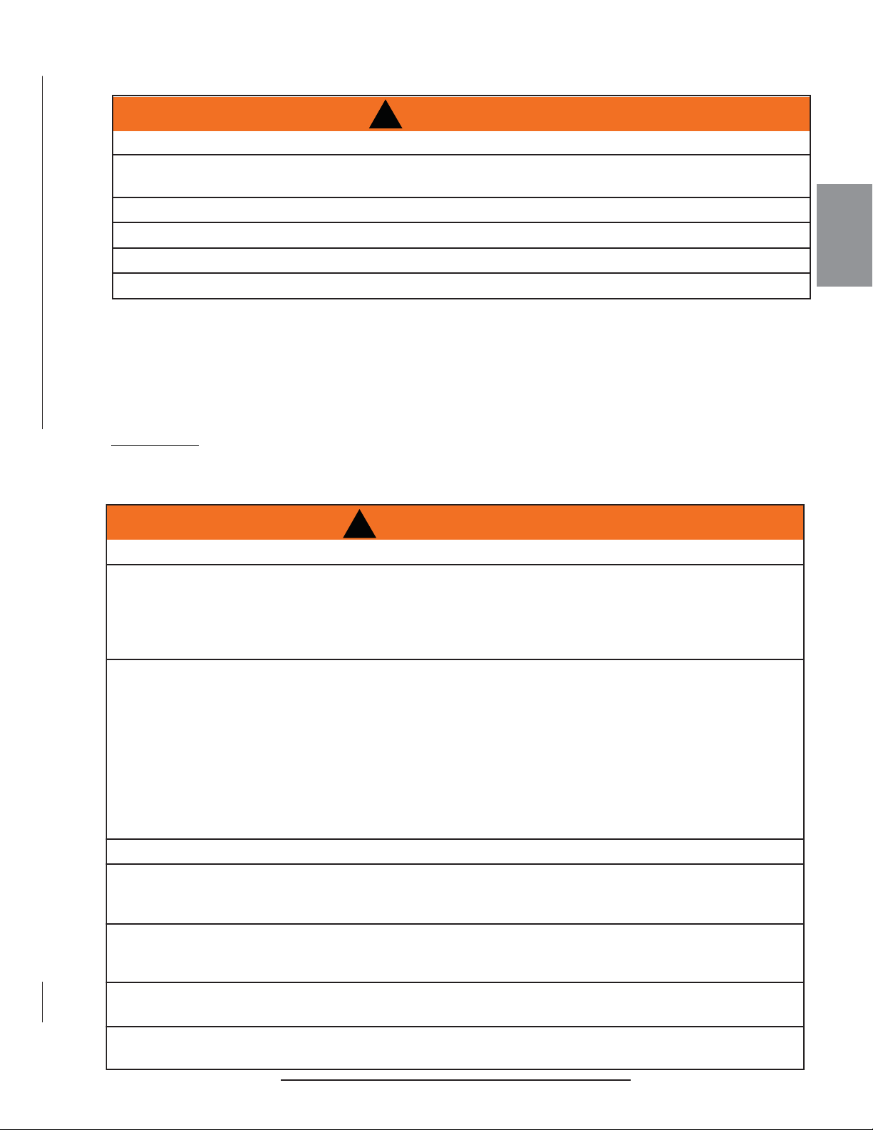
FR
W415-1476 / A / 10.12.16
51
!
AVERTISSEMENT
PORTEZ DES GANTS ET DES LUNETTES DE PROTECTION.
SUIVEZ ATTENTIVEMENT LES INSTRUCTIONS POUR L'ASSEMBLAGE DE LA CHEMINÉE ET DES
AUTRES COMPOSANTS NÉCESSAIRES À L'INSTALLATION DE L’APPAREIL. TOUTE OMISSION
POURRAIT CAUSER UN INCENDIE, PARTICULIÈREMENT SI DES MATÉRIAUX COMBUSTIBLES SONT
TROP PRÈS DE L’APPAREIL OU DE LA CHEMINÉE ET QUE DES OUVERTURES D'AIR SONT
BLOQUÉES, EMPÊCHANT LA LIBRE CIRCULATION DE L'AIR DE REFROIDISSEMENT.
N'INSTALLEZ PAS LA PRISE D'AIR EXTÉRIEUR DANS LE GARAGE. LES PRODUITS D'ÉCHAPPEMENT
PROVENANT DES MOTEURS À ESSENCE SONT DANGEREUX.
N'INSTALLEZ PAS LA PRISE D'AIR EXTÉRIEUR DANS UN GRENIER, UN SOUS-SOL OU AU-DESSUS
DU TOIT OÙ D'AUTRES APPAREILS DE CHAUFFAGE, DES VENTILATEURS ET DES CHEMINÉES
ÉVACUENT OU TIRENT DE L'AIR. CES MESURES RÉDUIRONT LES POSSIBILITÉS DE REFOULEMENT
DE FUMÉE OU UNE INVERSION DU DÉBIT D'AIR. L'ENTRÉE DE LA PRISE D'AIR DOIT DEMEURER
DÉGAGÉE DE FEUILLES, DE DÉBRIS, DE GLACE OU DE NEIGE. ELLE DOIT ÊTRE DÉGAGÉE
LORSQUE L'APPAREIL FONCTIONNE AFIN QUE LA PIÈCE NE SOIT PAS PRIVÉE D'AIR, CE QUI PEUT
CAUSER DES REFOULEMENTS DE FUMÉE OU UNE INCAPACITÉ À MAINTENIR UN FEU. LES
REFOULEMENTS DE FUMÉE PEUVENT AUSSI DÉCLENCHER LES DÉTECTEURS DE FUMÉE.
UNE PRESSION NÉGATIVE DANS LA MAISON POURRAIT NUIRE AU RENDEMENT DE L’APPAREIL.
AFIN D’ÉVITER TOUT CONTACT AVEC DE L’ISOLANT QUI S’AFFAISSE, L’APPAREIL NE DOIT PAS
ÊTRE INSTALLÉ CONTRE UN COUPE-VAPEUR OU DE L’ISOLANT À DÉCOUVERT. UNE SURCHAUFFE
LOCALISÉE PEUT SURVENIR ET UN INCENDIE POURRAIT S’ENSUIVRE.
N’UTILISEZ PAS DE COMPROMIS DE FORTUNE LORS DE L’INSTALLATION. N’OBSTRUEZ PAS,
ENTIÈREMENT NI PARTIELLEMENT, LES OUVERTURES D’AIR, LES GRILLES OU LES PERSIENNES.
N’AJOUTEZ PAS DE HOTTE.
.POUR PRÉVENIR DES BLESSURES GARDEZ VOS OUTILS À MAIN EN BON ÉTAT, AFFÛTEZ LES
TRANCHANTS ET ASSUREZ-VOUS QUE LES MANCHES SONT SOLIDES.
EN TOUT TEMPS, CONSERVEZ L'ESPACE VIDE MINIMAL REQUIS À L'ENCEINTE AFIN DE PRÉVENIR
LES INCENDIES.
68.3C
3.4.2 MAISON MOBILE
!
AVERTISSEMENT
N’INSTALLEZ PAS CET APPARIEL DANS UNE CHAMBRE À COUCHER.
N’INSTALLEZ PAS CET APPARIEL DANS UNE FAÇON À COMPROMETTRE L’INTÉGRITÉ
STRUCTURALE DU PLANCHER, MURS, PLAFOND OU TOIT DE LA MAISON MOBILE.
L’APPARIEL DOIT ÊTRE APPROVISIONNÉ EN AIR COMBURANT EXTÉRIEUR.
L’APPARIEL DOIT ÊTRE BOULONNÉ AU PLANCHER
INSTALLEZ CONFORMÉMENT À LA NORME 24 CFR. PART 3290 (HUD).
UTILISEZ UNE CHIMINÉE DE TYPE UL 103ht S629 (2100°F) CERTIFIÉE POUR LA COMBUSTION DE BOIS.
MODÈLE S1 EST HOMOLOGUÉS POUR INSTALLATION DANS LES MAISONS MOBILES AUX
ÉTATS-UNIS ET CANADA.
MODÈLE S4 EST HOMOLOGUÉS POUR INSTALLATION DANS LES MAISONS MOBILES AUX
ÉTATS-UNIS UNIQUEMENT.
MODÈLE S9 N’EST PAS HOMOLOGUÉS POUR INSTALLATION DANS LES MAISONS MOBILES AUX
ÉTATS-UNIS NI CANADA.
REMARQUE: Tous les appareils dans les maisons mobiles doivent être boulonné au plancher du
maison mobile.
4.0 INSTALLATION

FR
W415-1476 / A / 10.12.16
52
!
AVERTISSEMENT
NE JAMAIS INSTALLER UN CONDUIT DE RACCORDEMENT À PAROI SIMPLE DANS UNE ENCEINTE.
LES TEMPÉRATURES PLUS ÉLEVÉES DE CE CONDUIT PEUVENT IRRADIER SUFFISAMMENT DE
CHALEUR AUX MATÉRIAUX COMBUSTIBLES POUR CAUSER UN INCENDIE.
NE RACCORDEZ PAS CET APPAREIL AU CONDUIT D’UNE CHEMINÉE DESSERVANT UN AUTRE APPAREIL.
POUR ÉVITER LE RISQUE D’INCENDIE, VOUS DEVEZ SUIVRE TOUTES LES INSTRUCTIONS À LA
LETTRE, INCLUANT LES DÉGAGEMENTS ENTRE LE SYSTÈME DE CONDUITS ET L’ENCEINTE.
AFIN DE PROTÉGER LES PIÈCES EXPOSÉES AUX INTEMPÉRIES CONTRE LA CORROSION, NOUS
CONSEILLONS QUE LE DESSUS DE L’ENCEINTE SOIT PEINT AVEC UNE PEINTURE ANTIROUILLE.
NE REMPLISSEZ AUCUN ESPACE CHARPENTÉ AUTOUR DU CONDUIT AVEC DE L’ISOLANT
OU TOUT AUTRE MATÉRIAU. L’ISOLANT POSÉ DANS CET ESPACE POURRAIT CAUSER LES
MATÉRIAUX COMBUSTIBLES AVOISINANTS À SURCHAUFFER.
CONSERVEZ UN DÉGAGEMENT MINIMAL DE 2” (25.4mm) À TOUTES LES PIÈCES DU SYSTÈME
DE CONDUITS EN TOUT TEMPS. OMETTRE DE CONSERVER CE DÉGAGEMENT DE 2” (25.4mm)
CAUSERA UN INCENDIE. NE REMPLISSEZ CET ESPACE AVEC AUCUN TYPE DE MATÉRIAU.
DES INSTRUCTIONS DÉTAILLÉES SUR L’INSTALLATION DU DESSUS DE L’ENCEINTE, DU COLLET
DE SOLIN ET DU CHAPEAU SONT INCLUSES AVEC CES PIÈCES. LE DÉGAGEMENT MINIMUM À
COMBUSTIBLE VARIERA SELON LEUR CONCEPTION.
NE COUPEZ PAS DE CHEVRONS NI DE SOLIVES DE PLAFOND SANS AVOIR CONSULTÉ AU
PRÉALABLE LES AUTORITÉS EN BÂTIMENT POUR VOUS ASSURER QUE L’INTÉGRITÉ DE LA
STRUCTURE N’EST PAS COMPROMISE.
DES ESPACEURS COUPE-FEU DOIVENT ÊTRE UTILISÉS LORSQUE LE SYSTÈME DE CONDUITS
TRAVERSE UN PLAFOND/PLANCHER.
LA LONGUEUR TOTALE DE LA COURSE HORIZONTALE NE DEVRAIT PAS EXCÉDER 40% DE
LA HAUTEUR DE LA CHEMINÉE À PARTIR DU DESSUS DU POÊLE. TOUTES LES COURSES
HORIZONTALES DOIVENT AVOIR UNE PENTE MINIMALE VERS LE HAUT DE 1/4” (21.2mm) PAR
PIED (mètre) ET TOUS LES RACCORDEMENTS DOIVENT ÊTRE SCELLÉS ET FIXÉS PAR TROIS VIS
AUTOPERCEUSES ESPACÉES ÉGALEMENT. UN TUYAU DE RACCORDEMENT NON ISOLÉ NE DOIT
PAS TRAVERSER UN GRENIER, UN ENTRETOIT, UN PLACARD OU AUTRE ENDROIT DISSIMULÉ,
OU TRAVERSER UN PLANCHER, UN PLAFOND, UN MUR OU UNE CLOISON, OU TOUTE AUTRE
CONSTRUCTION COMBUSTIBLE.
N’UTILISEZ AUCUN MATÉRIAU DE FORTUNE DURANT L’INSTALLATION.
63.8A
4.1 CHEMINÉE
Votre appareil peut être raccordé à une cheminée de maçonnerie ou préfabriquée. Si vous utilisez une
cheminée préfabriquée, elle doit se conformer aux normes ULCS629 (au Canada) ou UL103 (É.-U.), être
de type HT (2100 °F/1149°C) et avoir un diamètre de 6’’ (152.4mm). N’utilisez que les composants spéciés
sans aucun substitut. Il est extrêmement important que la cheminée soit installée selon les spéci cations
du fabricant. Les directives d’installations du fabricant et les dégagements spéci és doivent toujours être
respectés en fonction des normes locales et nationales. Conformez-vous aux codes d’installation CSA B365
et CSA C22.1 au Canada et aux codes ANSI NFPA 70 et ANSI NFPA 211 aux États-Unis.
La cheminée et le conduit de raccordement doivent être gardés en bonne condition et propres.
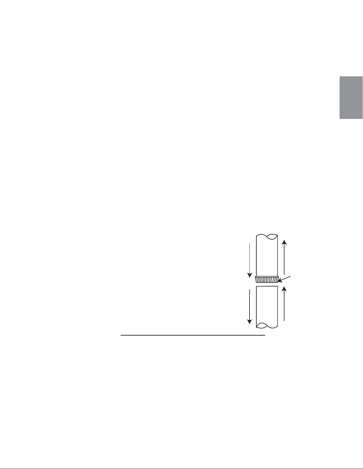
FR
W415-1476 / A / 10.12.16
53
Votre conduit de raccordement et votre cheminée doivent avoir le même diamètre que le tuyau
d’échappement de l’appareil. Le tuyau de l’appareil doit être en acier aluminié ou en acier laminé à froid d’une
épaisseur minimale de calibre 24 (0.6mm). Il est strictement interdit d’utiliser de l’acier galvanisé.
Un conduit de raccordement à paroi simple de 6” (152.4mm) de diamètre, servant à raccorder l’appareil
à la cheminée, doit être installé avec l’extrémité gaufrée dans la buse de l’appareil. Ceci permettra à la
condensation qui se forme dans le conduit de raccordement de l’appareil de s’écouler dans la chambre de
combustion. Chaque joint du conduit de raccordement doit être xé à l’aide d’au moins trois vis autoperceuses.
Les recommandations suivantes pourraient être utiles pour l’installation du conduit de raccordement.
• Le conduit de raccordement doit être court et droit. Pour une performance optimale, toutes les courses
horizontales devraient avoir une élévation minimale de 1/4” (6.4mm) par pied (0.9m) et l’extrémité
supérieure de la section devrait être dirigée vers la cheminée. A n d’assurer un fonctionnement sécuritaire
et adéquat de l’appareil, consultez les instructions de la section « INSTALLATION ».
• Pour assurez un tirage adéquat, la longueur horizontale du conduit ne doit jamais dépasser 8 (2.4m) à 10
pieds (3.1m). Dans le cas d’une installation verticale, la longueur totale du conduit peut être plus longue et
le raccordement à la cheminée peut être fait sans problème au niveau du plafond.
• Un système de conduits ne devrait jamais avoir plus que deux coudes de 90°. Avant d’utiliser un coude
de 90°, installez une section verticale d’au moins deux pieds (0.6m) à partir de la buse.
• Le conduit ne doit pas passer dans un matériel combustible ou un espace fermé (tels un grenier, un
entretoit ou un placard). S’il passe à travers un mur, un plafond ou dans une cheminée de maçonnerie,
utilisez soit des composants de cheminée conçus pour cet usage, ou des moyens acceptables de
l’autorité compétente locale.
4.1.1 INSTALLATION DE LA CHEMINÉE
C
e
t
appare
il
d
o
it
êt
re raccor
dé
à
:
A
. Une cheminée qui se conforme aux exigences des
cheminées préfabriquées de type HT résidentiel ou
B. Une cheminée en maçonnerie avec chemisage
intégral conforme aux codes et aux exigences.
Ventilez le poêle dans une cheminée de maçonnerie
ou dans une cheminée isolée en acier inoxydable
certifi ée. Le tuyau de raccordement de 6” (152,4mm)
de diamètre doit être aussi court et aussi droit
que possible. Le raccordement à la cheminée de
maçonnerie doit se faire à l’aide d’un manchon
métallique ou de maçonnerie cimenté en place.
VERS LA
BUSE DE
L’APPAREIL
DIRECTION
DES GAZ DE
COMBUSTION
EMBOUT MÂLE
DU CONDUIT
DE RACCOR-
DEMENT
58.1B
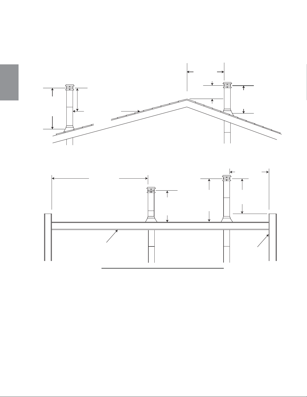
FR
W415-1476 / A / 10.12.16
54
4.1.2 AJOUT DE SECTIONS
A
joutez des sections de cheminée, selon les instructions d’installation des manufacturiers. La cheminée doit
dépasser le toit d’au moins 3’ (0,9m) de son point de contact avec la toiture, et 2’ (0,6m) de tout mur, toit ou
édifi ce se trouvant à l’intérieur d’une distance horizontale de 10’ (3,1m).
59.1B
3 PI
(1m)
MIN
3 PI (1m)
MIN
10 PI (3m)
OU PLUS
TOIT PLAT
MUR
FAîTE
MOINS DE
10 PIED
(3m)
2 PI (0.6m) MIN
3 PI (1m)
MIN
2 PI (0.6m)
MIN
MOINS DE
10 PIED
(3m)
3 PI (1m)
MIN
2 PI (0.6m)
MIN
10 PI (3m) DE
LA LIGNE DE
TOIT LE PLUS
PRÉS
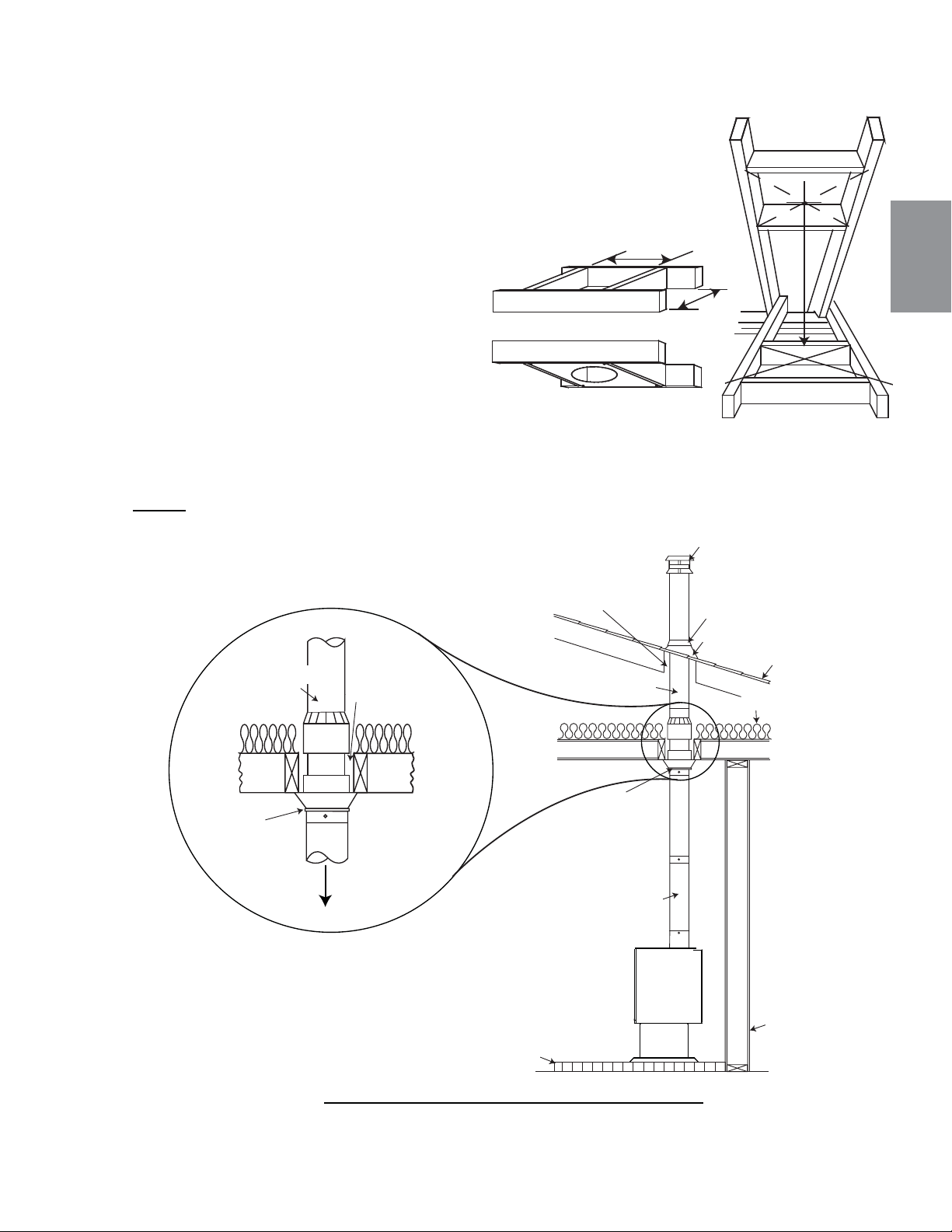
FR
W415-1476 / A / 10.12.16
55
4.1.3 TYPIQUE À TRAVERS LE PLAFOND
A. Mettez l’appareil en place. Repérez le centre de la buse de façon à ne pas
avoir à couper les solives. Utilisez un fi l à plomb pour aligner le centre de la
buse.
B. Découpez et charpentez une ouverture dans le plafond de façon à fournir
un dégagement de 2” (50,8mm) entre la cheminée et les matériaux
combustibles. Ne remplissez cet espace avec aucun type de matériau.
Fixez des entretoises entre les solives pour assurer
un support additionnel. Pour tout plancher
ou plafond traversés par la cheminée, des
espaceurs coupe-feu doivent être fi xés à la
base de chaque ouverture charpentée. Si
la cheminée traverse le grenier, un écran
de protection pour chevrons est requis.
C. Tenez un fi l à plomb à partir du dessous
du toit pour déterminer où doit se
trouver l’ouverture du toit. Découpez et
charpentez une ouverture dans le toit tout
en
conservant le dégagement de 2” (50,8mm).
NOTE : La cheminée doit être supportée au plafond ou au toit afi n que son poids ne repose pas sur
l’appareil et son installation doit être conforme aux instructions de son fabricant.
60.1B
ENTRETOISES
ESPACEUR COUPE-FEU
FACE INFÉRIEURE DES
SOLIVES
BASE DE
PROTECTION
TOIT
SOLIN DE TOIT
COLLET DE SOLIN
TERMINAISON
MUR
COMBUSTIBLE
CONSERVER
2” (50.8mm)
DE DÉGAGEMENT
CONDUIT DE
RACCORDEMENT
SUPPORT À
CONDUIT
CHIMINÉE
HOMOLOGUÉE
INSOLANT
SUPPORT
À CONDUIT
DÉGAGEMENT
RECOMMANDÉ
VERS
LE POÊLE
CHIMINÉE
HOMOLOGUÉE
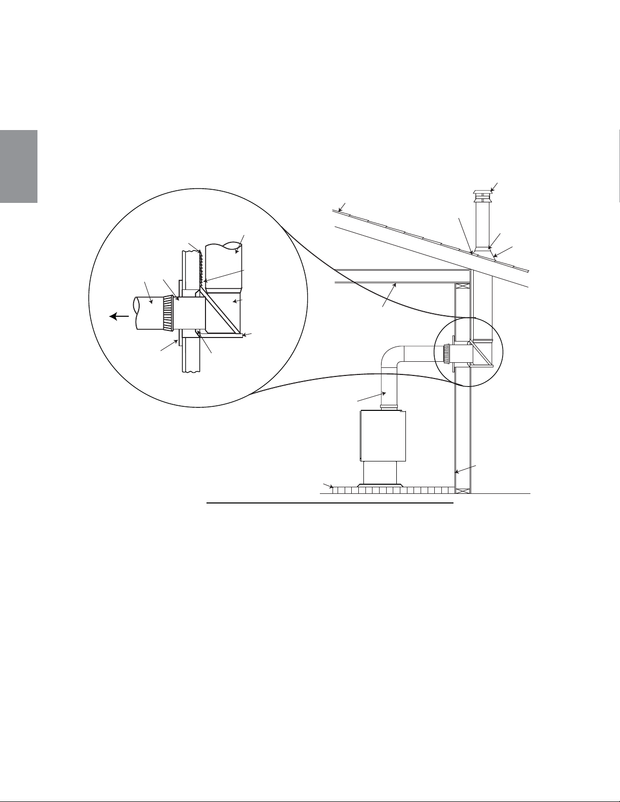
FR
W415-1476 / A / 10.12.16
56
4.1.4 INSTALLATION TYPIQUE À TRAVERS UN MUR
Si possible, l’installation des conduits de raccordement ne doit pas passer à travers un mur combustible.
S’il faut absolument passer à travers un mur combustible, consultez votre inspecteur en bâtiment avant de
procéder. Consultez aussi le fabricant des conduits de raccordement pour connaître toutes les exigences
particulières.
Consultez votre détaillant pour obtenir les composants de raccordement muraux dont vous auriez besoin.
N’utilisez que les pièces qui ont été testées et certifi ées pour des installations à travers un mur.
61.1A
BASE DE
PROTECTION
TOIT
SOLIN
DE TOIT
COLLET DE SOLIN
TERMINAISON
MUR
COMBUSTIBLE
CONDUIT DE
RACCORDEMENT
CONSERVER UN
DÉGAGEMENT DE 2”
(50,8mm) À TRAVERS
L’AVANT-TOIT
PLAFOND
COMBUSTIBLE
MUR EXTÉRIEUR
COMBUSTIBLE
2” (50,8mm)
CLEARANCE
RACCORD EN
«T» ISOLÉ
SUPPORT
MURAL
ESPACEUR
MURAL OU MUR
EXTÉRIEUR
CONDUIT DE
RACCORDEMENT
CHIMINÉE
HOMOLOGUÉE
VERS
L’APPAREIL
COUPE-FEU
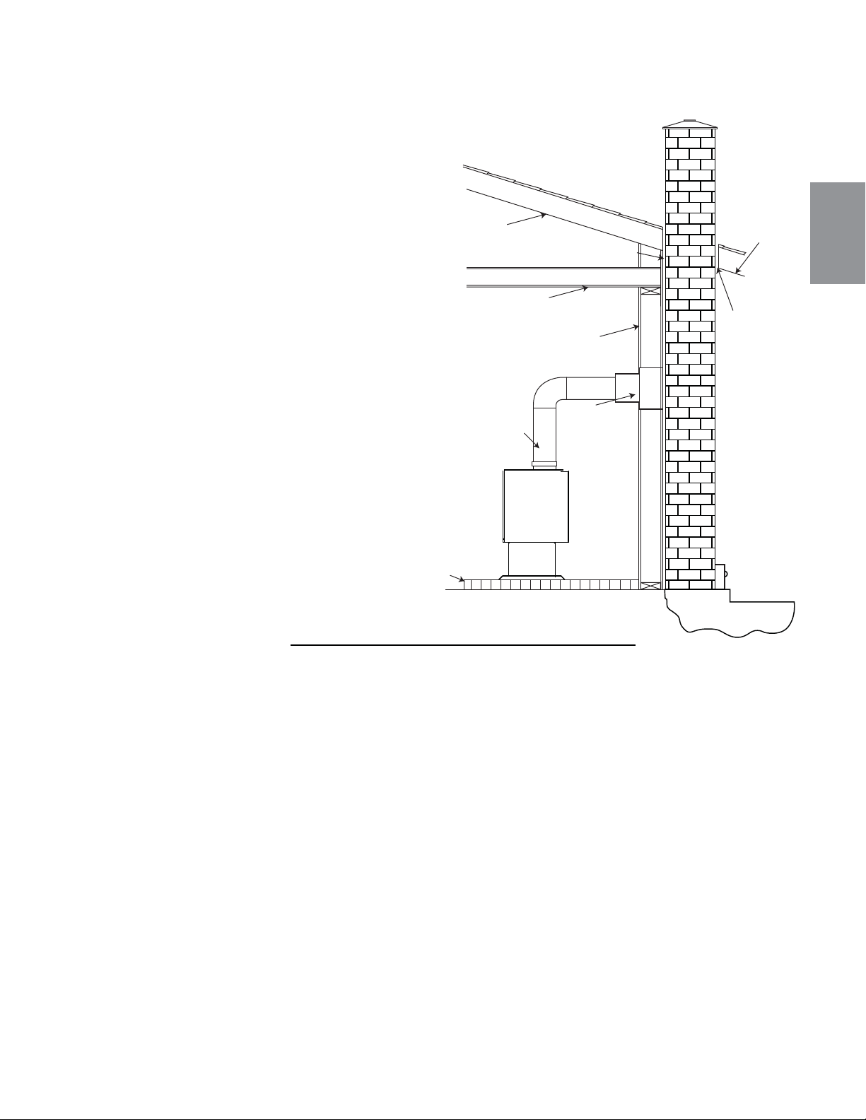
FR
W415-1476 / A / 10.12.16
57
4.1.5 INSTALLATION TYPIQUE DANS UNE CHEMINÉE DE MAÇONNERIE EXISTANTE
Vous pouvez aussi installer votre appareil en
utilisant votre cheminée de maçonnerie existante.
Pour ce faire, suivez les directives suivantes.
Nous vous conseillons d’installer un coupe-feu
préfabriqué ou d’en construire un. Si vous
utilisez une cheminée en maçonnerie, vous
devez vous assurer qu’elle réponde aux
normes de construction de votre région.
Elle doit être construite de briques d’argile
réfractaire, de tuiles de métal ou d’argile
cimentés ensemble avec du ciment
réfractaire. (Les conduits de cheminée
ronds sont les plus effi caces). La maximum
du conduit carré est 8” (203,2mm) x 8”
(203,2mm) ou 6” (152,4mm) pour une
conduit circulaire.
62.1A
BASE DE
PROTECTION
CONDUIT DE
RACCORDEMENT
MUR COMBUSTIBLE
DÉGAGEMENT
AVANT-TOIT
CHEVRON
DÉGAGEMENT AVEC UN COUPE-FEU
SOLIVE DE PLAFOND
COUPE-FEU
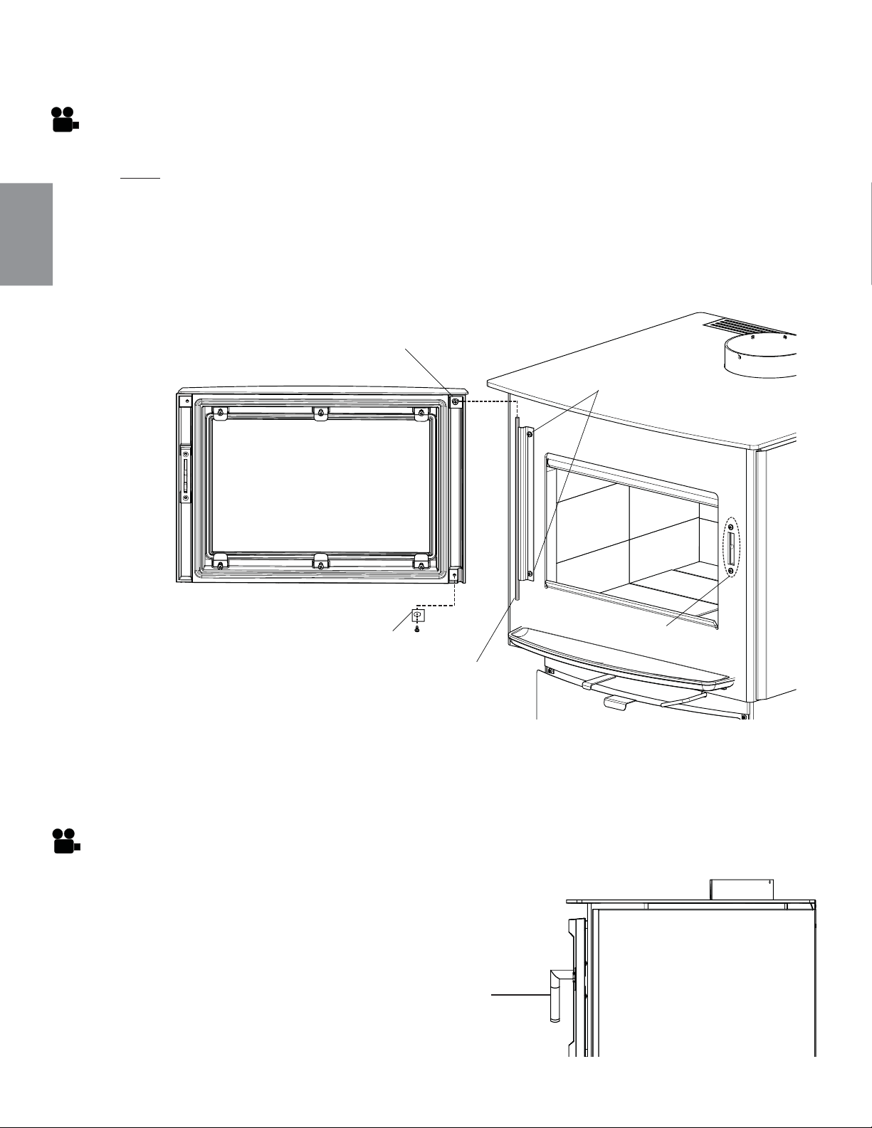
FR
W415-1476 / A / 10.12.16
58
5.0 FINITIONS
A. Retirez le support de charnière inférieure de la porte en enlevant la vis, comme illustré ci-dessous,
puis desserrez le support de charnière supérieure de la porte.
B. Soulevez la porte pour la dégager de la tige de la charnière.
C. Placez délicatement la porte face vers le bas, sur une surface douce afi n d’éviter d’égratignere la
peinture.
D. Suivez les instructions en sens inverse pour installer la porte.
5.1 ENLÈVEMENT ET INSTALLATION DE LA PORTE
TIGE DE
CHARNIÈRE
SUPPORT DE CHARNIÈRE DE LA PORTE
VIS DE CHARNIÈRE
BOÎTIER DU BLOC
DE LOQUET
SUPPORT DE CHARNIÈRE
DE LA PORTE
Assurez-vous de bien tenir la porte en tout temps.
NOTE: Nous recommandons que deux personnes effectuent cette installation.
5.1a AJUSTEMENT DE LA PORTE
A. Desserrez les deux vis de charnière pour ajuster la position horizontale de la porte.
B. Serrez les deux vis de charnière lorsque la porte est à la position souhaitée.
5.1b AJUSTEMENT DU BOÎTIER DU BLOC DE LOQUET
A. Desserrez les deux vis du boîtier du bloc de loquet.
B. Déplacez le boîtier vers le haut ou vers le bas jusqu’à
ce que la poignée ait l’angle désiré. (ASTUCE: Un
déplacement du boîtier logement vers le haut a pour
résultat en une angle du poignée plus bas. Déplacement
vers le bas résultat en une angle du poignée plus haut.
ANGLE DE LA POIGNÉE EN
POSITION FERMÉE
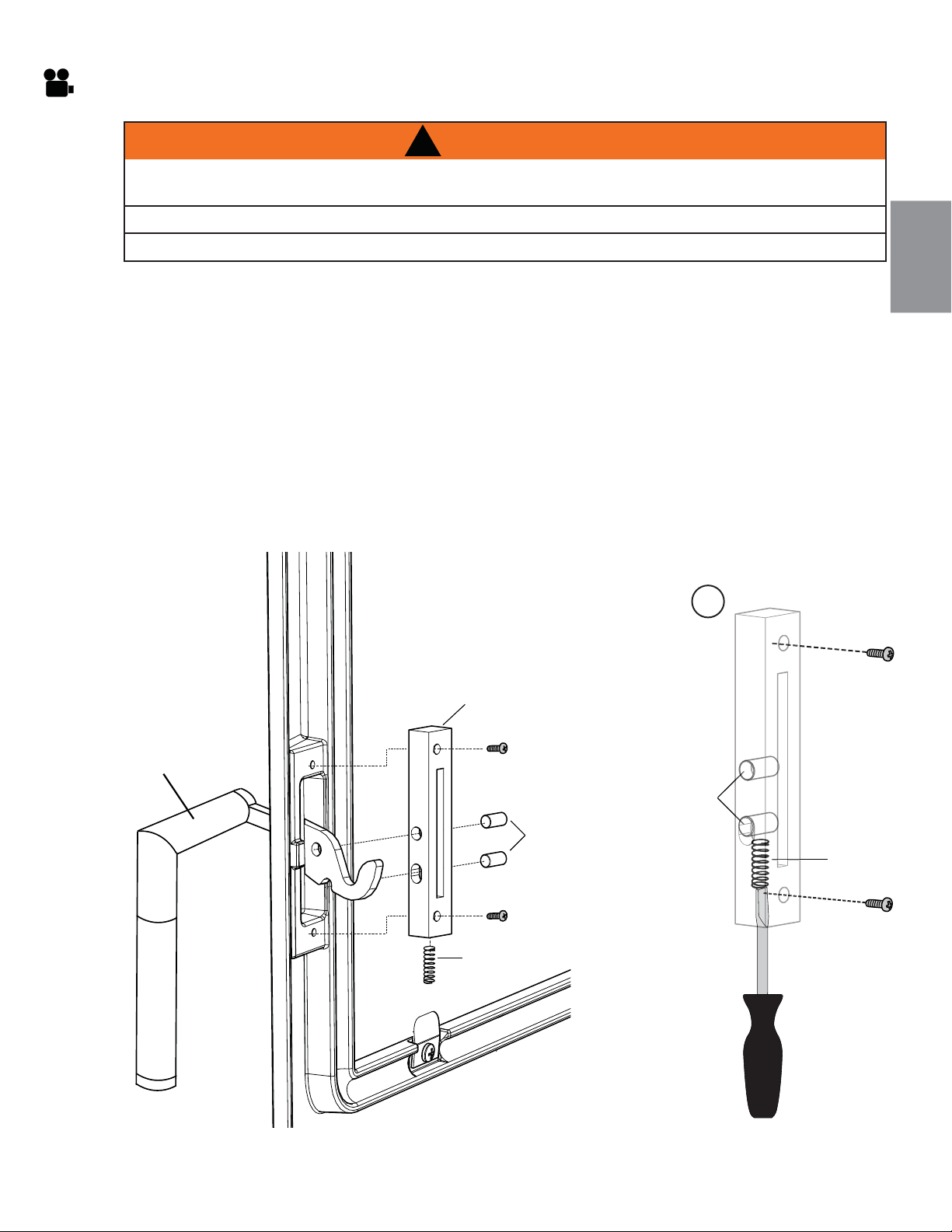
FR
W415-1476 / A / 10.12.16
59
5.2 INSTALLATION DE LA POIGNÉE DE PORTE ET DE LA PORTE
A. Retirez les deux vis qui fi xent le bloc de loquet à la porte.
B. Tirez le poignée vers l’intérieur de la porte et retirez les composants du bloc de loquet, puis retirez le
bloc de loquet et le poignée. Remplacez les composants usés ou endommagés.
C. Pour réinstaller la poignée de porte, prenez le bloc de loquet et le poignée de porte, puis alignez les
trous de vis du haut et du bas avec la porte, comme illustré.
D. Serrez légèrement la vis supérieure, puis installez les deux goupilles, comme illustré.
E. Pour installer le ressort, glissez-le dans le bas du bloc de loquet, puis installez la vis. Appliquez
une petite quantité de graisse à haute température sur le ressort avant l’installation. ASTUCE:
Comprimez le ressort à l’aide d’un tournevis à tête plate; cela facilite l’installation de la vis,
comme illustré ci-dessous.
F.
Afi n d’assurer une bonne installation, le support de la poignée doit avoir la possibilité de demeurer dans
une position vers le haut. De plus, le support de la poignée doit s’engager sans problème dans le foyer.
E
RESSORT
POIGNÉE
BLOC DE LOQUET
ÉPINGLES
ÉPINGLES
RESSOR
T
!
AVERTISSEMENT
FAIRE FONCTIONNER CET APPAREIL AVEC LES PORTES OUERTES OU ENTROUVERTES CRÉE UN
RISQUE D’INCENDIE DE CHEMINÉE OU DOMICILE.
NE FRAPPEZ PAS ET NE CLAQUEZ PAS LA PORTE.
N’ENLEVEZ JAMAIS LA PORTE LORSQUE L’APPAREIL EST CHAUD.
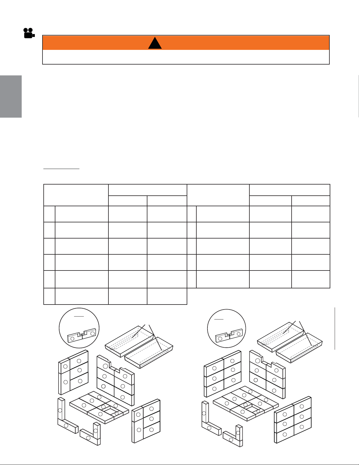
FR
W415-1476 / A / 10.12.16
60
5.3 INSTALLATION DES BRIQUES ET DES DÉFLECTEURS EN FIBRE
Une fois l’installation de l’appareil et du tuyau de raccordement complétée, mettez les briques en
place en procédant tel qu’illustré précédemment.
A. Installez les briques de plancher, de l’arrière vers l’avant de l’appareil.
B. Avant d’installer les briques arrière, desserrez la vis du support et assurez-vous qu’il a été déplacé
vers l’avant. Installez les six briques sur la paroi arrière, en les faisant pivoter sous le support à
briques, puis resserrez la vis.
C. Installez les premier deux rangs de briques de comme illustrée au dessous.
D. Pivotez les défl ecteurs en fi bre à sa place avec la support de brique en bas et vers l’extérieur de
l’appareil.Glisser le premier rang de briques à sa place pour soutenir les défl ecteurs. Le défl ecteur
doit se reposer à plat sur la rangée extérieure de briques et aussi sur la bride à l’écran du collecteur
Assurez-vous que les défl ecteurs sont complètement poussés vers l’arrière de la chambre de
combustion, en laissant un espace minimum d’un pouce (25mm) à l’avant. Ceci permettra aux
résidus des gaz de combustion d’être évacués de la chambre de combustion.
E. Installez la reste des briques devant l’ouverture de l’appareil, comme illustrée au dessous.
REMARQUE: Ne faites pas fonctionner l’appareil si le défl ecteur, brique ou l’écran du collecteur n’est
pas en place.
Tous les briques réfractaires sont de 1 ¼ pouces (32mm) d’épaisseur
DIMENSIONS DE
BRIQUES
PART #
DIMENSIONS DE
BRIQUES
PART #
S1 S4 S1 S4
A
4 1/2” x 9”
(114mm x 229mm)
W090-0001
X12
W090-0001
X18
G
2 1/4” x 9”
(57mm x 229mm)
W090-0018
X1
W090-0018
X1
B
3” x 9” (Moulée)
(6mm x 229mm)
W090-0002
X2
W090-0002
X2
H
1 3/4” x 4 3/4”
(64mm x 121mm)
W090-0216
X1
W090-0216
X1
C
4 1/2” x 4 1/2”
(114mm x 144mm)
W090-0003
X2
N/A
I
2 1/2” x 4 1/2”
(64mm x 114mm)
W090-0016
X1
W090-0016
X1
D
3” x 9”
(76mm x 229mm)
W090-0166
X2
W090-0166
X2
J
1 1/2” x 4 1/2”
(38mm x 114mm)
W090-0017
X1
W090-0017
X1
E
4 1/2” x 9”(Entaillée)
(114mm x 229mm)
W090-0207
X1
W090-0207
X1
K
4 1/2” x 8 1/4”
(114mm x 216mm)
W090-0184
X3
W090-0184
X3
F
4 1/2” x 9”(Entaillée)
(114mm x 229mm)
W090-0208
X1
W090-0208
X1
!
AVERTISSEMENT
L’UTILISATION DE L’APPAREIL SANS LES DÉFLECTEURS PEUT CAUSER DES TEMPÉRATURES
EXCESSIVES QUI POURRAIENT ENDOMMAGER L’APPAREIL, LA CHEMINÉE ET L’ENCEINTE.
RETENUE
DU BRIQUE
A
A
A
A
A
A
A
A
A
A
A
A
D
D
B
B
C
E
F
I
J
G
E
F
NOTE:
BRIQUES E & F
SONT ENTAILLÉ
À ARRIÈRE
H
(Déflecteurs
en Fibre)
W018-0077 X2
A
C
K
K
K
S1
(
Déflecteur en Fib
r
W018-0078 X2
RETENUE
DU BRIQUE
D
D
A
A
A
A
A
A
A
A
A
A
A
A
A
B
B
E
F
I
J
G
H
A
A
A
A
A
A
NOTE: BRIQUES
E & F SONT ENTAILLÉ
À L’ARRIÈRE
F
E
K
K
K
S4
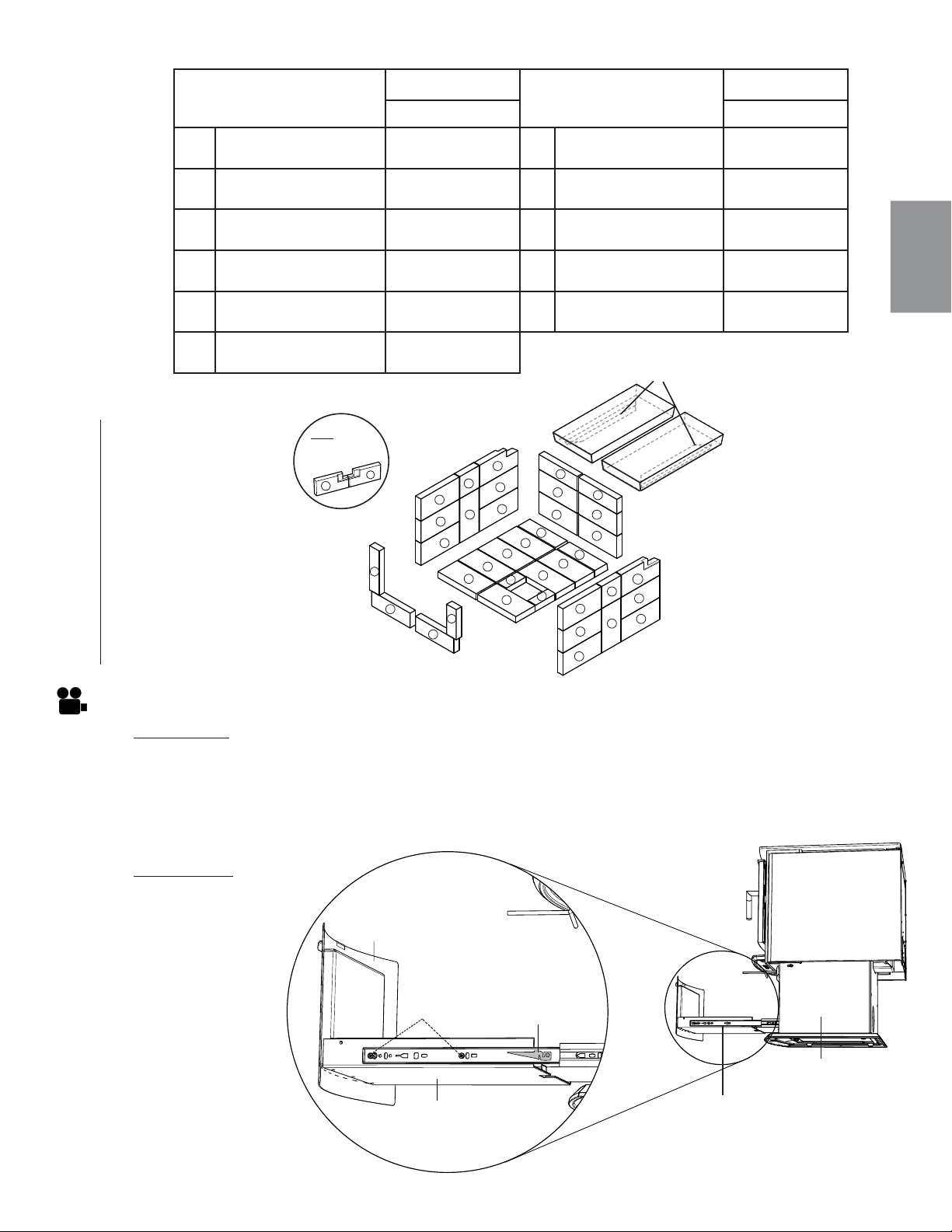
FR
W415-1476 / A / 10.12.16
61
S9
DIMENSIONS DE
BRIQUES
PART #
DIMENSIONS DE
BRIQUES
PART #
S9 S9
A
4 1/2” x 9”
(114mm x 229mm)
W090-0015
X20
G
2 1/4” x 9”
(57mm x 229mm)
W090-0018
X1
B
3” x 9” (Moulée)
(6mm x 229mm)
W090-0002
X2
H
1 3/4” x 4 3/4”
(64mm x 121mm)
W090-0216
X1
C
4 1/2” x 4 1/2”
(114mm x 144mm)
W090-0003
X2
I
2 1/2” x 4 1/2”
(64mm x 114mm)
W090-0016
X1
D
3” x 9”
(76mm x 229mm)
W090-0166
X4
J
1 1/2” x 4 1/2”
(38mm x 114mm)
W090-0017
X1
E
4 1/2” x 9”(Entaillée)
(114mm x 229mm)
W090-0207
X1
K
4 1/2” x 8 1/4”
(114mm x 216mm)
W090-0184
X3
F
4 1/2” x 9”(Entaillée)
(114mm x 229mm)
W090-0208
X1
A
A
A
A
A
A
A
A
A
A
A
A
A
A
A
A
A
A
B
B
D
D
I
J
G
A
A
C
C
D
D
F
E
(Déflecteur en Fibre)
W018-0130 X2
H
RETENUE DE
BRIQUE
E
NOTE: BRIQUES
E & F SONT ENTAILLÉ
À L’ARRIÈRE
F
K
K
K
5.4 AJUSTEMENT DU TIROIR À CENDRES
REMARQUE: Si un ajustement du tiroir à cendres est nécessaire, des zones d’ajustement sont situées
sur les côtés et le fond du tiroir à cendres, comme illustré ci-dessous.
A. Retirez le tiroir à cendres de l’appareil en appuyant vers le bas sur le levier de déconnexion du tiroir du
côté droit, et vers le haut sur le levier du côté gauche, puis tirez le tiroir à cendres hors du piédestal.
B. Pour modifi er l’espacement entre le couvercle du tiroir à cendres et le piédestal, desserrez les vis
d’ajustement latérales (des deux côtés) et positionnez à la distance souhaitée, puis serrez les vis.
FENTES / VIS
D’AJUSTEMENT
LATÉRALES
COUVERCLE
DU TIROIR À
CENDRES
BOÎTIER DU TIROIR
À CENDRES
LEVIER DE
DÉCONNEXION
DU TIROIR
PIÉDESTAL
TIROIR À CENDRES
REMARQUE:
Toujours s’assurer
que le cendrier est
complètement refroidi
avant de le retirer du
tiroir à cendres.
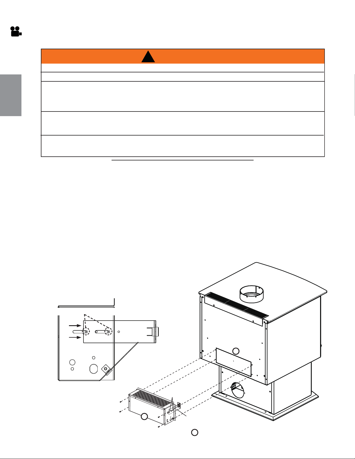
FR
W415-1476 / A / 10.12.16
62
PLAQUE
SOUFFLERIE
C
D
B
POINÇONNÉE
SUPPORT DU
THERMODISQUE
VIS
Il est possible d’installer une souffl erie optionnelle (EP65) avec un interrupteur à vitesse variable servant à faire partir
et arrêter la souffl erie ainsi qu’à contrôler sa vitesse et une détecteur thermostatique pour activé par la souffl erie.
La poussière de gypse pénétrera dans le roulement à billes de la souffl erie causant des dommages
irréparables. Vous devez éviter que cette poussière n’entre en contact avec la souffl erie ou son compartiment.
Tout dommage causé par ce problème ne sera pas couvert par la garantie.
L’utilisation de la souffl erie accroît le débit de chaleur.
A. Assurez-vous que le support du thermodisque est dans la position correcte, voir la Figure 1.
B. Enlevez la plaque poinçonnée de l’arrière de l’appareil.
C. Installez la souffl erie et son boîtier tel qu’illustré en Figure 2, en utilisant les quatre vis fournies.
D. Desserrez le support de l’interrupteur thermique
(deux vis) et faites glisser le support vers l’avant
jusqu’à ce que l’interrupteur thermique touche
l’arrière de la chambre de combustion et fi xez.
Fig. 2
6.0 INSTALLATIONS DES ENSEMBLES OPTIONNELLE
6.1 INSTALLATION DE L’ ENSEMBLE DU SOUFFLERIE
!
AVERTISSEMENT
RISQUE D’INCENDIE ET DE CHOC ÉLECTRIQUE.
COUPEZ L’ALIMENTATION EN GAZ ET L’ALIMENTATION ÉLECTRIQUE AVANT DE PROCÉDER À L’ENTRETIEN DE L’APPAREIL.
N’UTILISEZ QUE LES ACCESSOIRES OPTIONNELS ET LES PIÈCES DE RECHANGE APPROUVÉS PAR WOLF
STEEL POUR CET APPAREIL. L’UTILISATION D’ACCESSOIRES NON LISTÉS (SOUFFLERIE, PORTES, PERSI-
ENNES, MOULURES, COMPOSANTS DE GAZ, COMPOSANTS D’ÉVACUATION, ETC.) POURRAIT ÊTRE NON
SÉCURITAIRE ET ANNULERA LA GARANTIE ET LA CERTIFICATION.
AFIN DE PRÉVENIR LES CHOCS ÉLECTRIQUES ET LES DOMMAGES CAUSÉS PAR LE FEU, ASSUREZ-VOUS
QUE LE CORDON D’ALIMENTATION DU VENTILATEUR N’ENTRE PAS EN CONTACT AVEC QUELCONQUE SUR-
FACE DE L’APPAREIL. NE FAITES PAS PASSER LE CORDON D’ALIMENTATION SOUS L’APPAREIL.
LE HARNAIS DE FILS FOURNI DANS L’ENSEMBLE DE SOUFFLERIE EST UN HARNAIS UNIVERSEL.
LORS DE SON INSTALLATION, ASSUREZ-VOUS QUE TOUT EXCÈS DE FIL EST CONFINÉ,
L’EMPÊCHANT AINSI D’ENTRER EN CONTACT AVEC DES OBJETS CHAUDS OU MOBILES.
51.5
6.1.1 INSTALLATION DE LA SOUFFLERIE
Fig. 1
SUPPORT DU THERMODISQUE
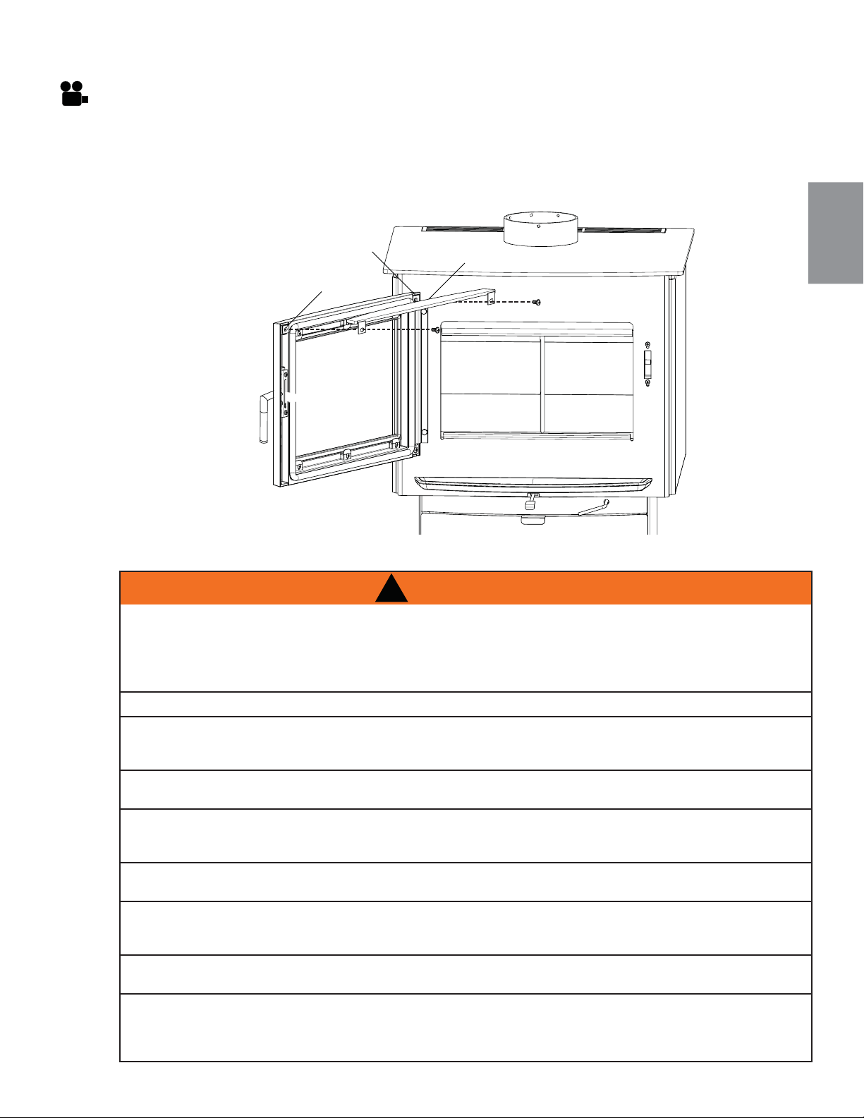
FR
W415-1476 / A / 10.12.16
63
7.1 GARNITURE DU PORTE
A. Ouvrir la porte de l’appareil.
B. Enlèver le vis aux côté gauche, tenir le gond support supérieure du porte en place.
C. Placer une rondelle contre la porte, aux côté gauche.
D. Placer la garniture en haut du porte, aligner les trous, puis fi xer en place.
GOND SUPPORT
SUPÉRIEURE
DU PORTE
GARNITURE DU PORTE
RONDELLE
7.0 FONCTIONNEMENT
!
AVERTISSEMENT
FAITES TOUJOURS FONCTIONNER CET APPAREIL AVEC LA PORTE FERMÉE ET VERROUILLÉE
SAUF DURANT L’ALLUMAGE ET LE RAVITAILLEMENT OU LORSQUE VOUS UTILISEZ LE PARE-
ÉTINCELLES. PORTEZ TOUJOURS DES GANTS POUR PRÉVENIR LES BLESSURES. NE LAISSEZ PAS
L’APPAREIL SANS SUPERVISION LORSQUE LES PORTES SONT DÉVERROUILLÉES OU LORSQUE
VOUS UTILISEZ LE PARE-ÉTINCELLES. DU BOIS INSTABLE POURRAIT TOMBER HORS DE LA
CHAMBRE DE COMBUSTION ET CRÉER UN RISQUE D’INCENDIE.
NE LAISSEZ JAMAIS LES ENFANTS SANS SURVEILLANCE LORSQU’UN FEU BRÛLE DANS L’APPAREIL.
N’UTILISEZ JAMAIS D’ESSENCE, DE COMBUSTIBLE À LANTERNE, DE KÉROSÈNE, D’ESSENCE À
BRIQUET OU AUTRES LIQUIDES POUR ALLUMER OU RAVIVER UN FEU DANS CET APPAREIL.
GARDEZ TOUS CES LIQUIDES ÉLOIGNÉS DE L’APPAREIL LORSQUE CELUI-CI FONCTIONNE.
LES OBJETS PLACÉS DEVANT L’APPAREIL DOIVENT ÊTRE GARDÉS À UNE DISTANCE D’AU
MOINS 48” (1,2m) DE LA FACE VITRÉE.
TOUTE MODIFICATION APPORTÉE À L’APPAREIL QUI N’A PAS ÉTÉ PRÉALABLEMENT APPOUVÉE
PAR ÉCRIT PAR LE LABORATOIRE D’ESSAI EST CONSIDÉRÉ COMME UNE VIOLATION DES
NORMES CSA B365 (CANADA) ET ANSI NFPA 211 (É.-U.).
OUVREZ LE CONTRÔLE DE COMBUSTION (ET LE REGISTRE S’IL YA LIEU) AVANT D’OUVRIR LA
PORTE DE L’APPAREIL.
L’APPAREIL EST CHAUD LORSQU’IL FONCTIONNE. TENIR LES ENFANTS, LES VÊTEMENTS ET LES
MEUBLES À L’ÉCART. LE CONTACT PEUT CAUSER DES BRÛLURES. PORTEZ DES GANTS
LORSQUE VOUS OPÉREZ VOTRE APPAREIL.
FAIRE FONCTIONNER VOTRE APPAREIL AVEC LES PORTES OUVERTES OU ENTROUVERTES
CONSTITUE UN RISQUE POUVANT CAUSER UN INCENDIE OU UN FEU DE CHEMINÉE.
CET APPAREIL DE BOIS A UN MINIMUM TAUX DE COMBUSTION FAIBLE DÉFINI PAR LE FABRICANT
QUI NE DOIT PAS ÊTRE MODIFIÉ. C’EST DANS LES RÈGLEMENTS FÉDÉRAUX AUX ÉTATS-UNIS
DE MODIFIER CE PARAMÈTRE OU AUTREMENT UTILISER CET APPAREIL D’UNE MANIÈRE
INCOMPATIBLE AVEC LES INSTRUCTIONS DE CE MANUEL.

FR
W415-1476 / A / 10.12.16
64
Votre appareil Napoléon certifi é aux normes EPA est un appareil de haute technologie conçu selon les
principes technologiques les plus avancés. Cet appareil est extrêmement hermétique et est équipé d’une
alimentation directe d’air comburant exclusive (ensemble optionnel), un dispositif de sécurité qui empêche
les écoulements afi n de garder votre maison exempte de monoxyde de carbone, advenant un refoulement de
cheminée ou une pression négative interne. Cette appareil requis une inspection et la réparation périodique
pour un bon fonctionnement. C’est dans les règlements fédéraux des États-Unis pour faire fonctionner
l’appareil d’une manière incompatible avec les instructions de ce manuel.
Le(s) premier(s) feu(x) de l’appareil sera/seront diffi cile(s) à partir et à maintenir tout en produisant qu’un peu
de chaleur. Ceci est le résultat de l’humidité émanant des briques réfractaires. Durant la période de rodage
(les premiers 2 ou 3 feux), ne faites que des petits feux en utilisant du bois d’allumage; cela permettra à
la brique de se conditionner. Ne vous inquiétez pas si de petites fi ssures apparaissent dans les briques
réfractaires. Cela est normal et ne pose aucun danger à la sécurité. La peinture peut également produire de
légères émanations pendant les premiers feux à cause du processus de cuisson; vous devrez ouvrir une porte
ou une fenêtre pour chasser les odeurs.
À l’allumage, un feu vif est requis. Placez des morceaux de papier grossièrement chiffonnés sur le plancher de
l’appareil et couvrez-les de bois d’allumage. Ouvrez complètement le contrôle de combustion en le déplaçant
complètement à droite. Allumez le papier et laissez la porte légèrement entrouverte (un pouce) jusqu’à ce que
tout le bois d’allumage soit enfl ammé. Pour maintenir un feu vif, un lit de braises doit se former et être entretenu.
Pendant le ravitaillement et raviver d’un incendie ou d’un refroidissement qui a été l’incendie a brûlé jusqu’à
la phase de charbon, de faire fonctionner l’appareil à un moyen à haut taux d’allumage pendant environ 10
minutes afi n de s’assurer que la température atteint 600°F (315°C).
Lentement, ajoutez des morceaux de bois plus gros (la taille de 2”x4”). Posez les morceaux dans le lit de
braises, parallèlement à l’arrière de l’appareil, tout en gardant une tranchée peu profonde entre les morceaux
de bois. Ainsi, l’air comburant primaire circulera directement dans la tranchée et allumera le bois. Lorsque
la fl ammée semble à son maximum, des bûches de dimensions moyennes peuvent être ajoutées. Une fois
que ces morceaux ont pris feu, fermez la porte doucement. (Le fait de fermer la porte immédiatement après
le chargement entraînera une diminution de température dans la chambre de combustion et se traduira
par une combustion insatisfaisante.) Rappelez-vous qu’il est plus effi cace de brûler des morceaux de bois
de dimensions moyennes à feu vif et de recharger plus souvent, que d’alimenter l’appareil avec des gros
morceaux qui produiront un feu languissant et ineffi cace qui salira la vitre.
Une fois que la porte est fermée, vous observerez un changement dans le comportement des fl ammes. Elles
devien-dront plus petites et plus paresseuses parce que le volume d’oxygène qui entre dans la chambre de
combustion est moindre. Cependant, les fl ammes sont plus effi caces. Elles continueront d’être paresseuses,
mais redeviendront plus grandes dès que les briques réfractaires auront été complètement réchauffées et que
la cheminée deviendra plus chaude, produisant ainsi un meilleur tirage. À ce stade, les grandes fl ammes que
vous observez lorsque la porte est ouverte tirent inutilement l’air réchauffé de la pièce dans la cheminée une
situation qui est certes indésirable. C’est pourquoi il faut toujours faire fonctionner l’appareil avec la porte
complètement fermée lorsque les morceaux de bois de dimensions moyennes sont enfl ammés.
Vous pouvez maintenant ajouter de plus gros morceaux de bois et faire fonctionner l’appareil normalement.
Une fois que l’appareil est complètement réchauffé, il brûlera très effi cacement en laissant échapper que très
peu de fumée par la cheminée. Il y aura un lit de braises orangées dans la chambre de combustion
et les fl ammes secondaires sautilleront juste au-dessous des défl ecteurs supérieurs. Vous pouvez sans
crainte remplir la chambre de combustion avec du bois jusqu’au sommet de la porte de chargement et vous
obtiendrez de meilleures fl ammes si vous maintenez la température du tuyau de l’appareil entre 250°F (120°C)
et 450°F (270°C). Un thermomètre de surface vous aidera à mieux contrôler la température.
Sans thermomètre, vous travaillez à l’aveuglette, sans aucune idée réelle du fonctionnement de votre appareil!
Un thermomètre d’appareil vous donne une référence quant à la performance de votre appareil et doit être
placé 18” (457mm) au-dessus de la conduit du chiminée de l’appareil. Installez le thermomètre selon les
instructions du fabricant.
Vous n’arrivez pas à faire partir votre feu?
Utilisez plus de bois d’allumage et de papier. Si la cheminée et le tuyau d’évacuation sont de grandeur
appropriée, et s’il y a suffi samment d’air comburant, alors le problème est causé par une quantité insuffi sante
de petits morceaux de bois d’allumage sec. Le bois d’allumage devrait avoir un diamètre équivalent à celui de
votre pouce.
Votre appareil n’émet pas assez de chaleur?
Une ou deux causes sont possibles. La porte de l’appareil a été fermée prématurément et l’appareil n’a pas
atteint sa température optimale. Ouvrez la porte et/ou le contrôle de combustion à nouveau afi n de repartir un
feu vif. Du bois mouillé pourrait être la deuxième cause. Un bois grésillant d’où s’échappe de l’humidité est le
symptôme typique.
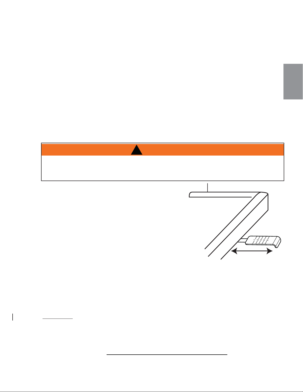
FR
W415-1476 / A / 10.12.16
65
7.2 MÉTHODE POUR ASSURER UNE COMBUSTION OPTIMALE
Pour une performance et une effi cacité optimales quant aux émissions, suivez les directives simples
suivantes lors de l’utilisation de votre appareil :
A. Maintenez une couche de braises chaudes de 2 po (51 mm).
B. Brûlez seulement du bois sec avec moins de 20% d’humidité et veillez à ce que la porte vitrée reste
propre.
C. Un thermomètre de poêle à bois doit indiquer une température moyenne de 350°F (176°C).
D. Lors d’une combustion normale, vous devez maintenir un niveau minimal d’émanations de fumée
provenant de la cheminée.
E. Inspectez et remplacez tous les composants nécessaires tels que les joints, les collecteurs, la vitre
et d’autres composants qui peuvent affecter l’effi cacité globale de l’appareil.
F. Assurez un tirage adéquat pour contrôler la rapidité de combustion et la température.
Reportez-vous aux sections FONCTIONNEMENT et ENTRETIEN pour plus de détails.
Le tirage est la force qui déplace l’air de la chambre de
combustion vers le haut, dans la cheminée. La force de tirage
de votre cheminée dépend de sa hauteur et de son diamètre,
de la géographie locale, des obstructions avoisinantes et autres
facteurs. Déplacer le contrôle d’air complètement à gauche
réduit la température.
Le contrôle d’air peut être réglé pour passer d’une combustion
lente à une combustion rapide en déplaçant la manette de la
gauche vers la droite.
Un tirage inadéquat peut causer des refoulements de fumée
dans la pièce via l’appareil et les points de raccordement des
conduits. Il peut également causer un blocage de la cheminée.
Un tirage trop grand provoquera des températures excessives
dans l’appareil, des composants de l’appareil ou des conduits de raccordements qui rougeoient ou une
combustion incontrôlable qui peut causer un feu de cheminée ou des dommages permanents à l’appareil.
Ne faites pas fonctionner l’appareil pendant plus de 30 minutes avec le contrôle d’air à « HIGH »
(complètement ouvert).
CET APPAREIL AU BOIS POSSÈDE UN TAUX MINIMAL DE COMBUSTION ÉTABLI PAR LE FABRICANT
QUI NE DOIT PAS ÊTRE MODIFIÉ. LES RÈGLEMENTS FÉDÉRAUX INTERDISENT EN ÉTATS-UNIS DE
MODIFIER CE RÉGLAGE OU D’UTILISER CET APPAREIL DE CHAUFFAGE D’UNE MANIÈRE ALLANT À
L’ENCONTRE DES INSTRUCTIONS DE FONCTIONNEMENT CONTENUES DANS CE MANUEL.
!
AVERTISSEMENT
7.3 CONTRÔLE D’AIR
91.1A
Toutes les maisons possédant un appareil à combustible solide devraient posséder au moins un extincteur
d’incendie dans un emplacement central connu de tous et au moins un détecteur de fumée et détecteur
monoxyde de carbone placé dans la pièce où l’appareil est situé. Si l’alarme se déclenche, corrigez la cause
mais ne désactivez pas, ou ne relocalisez pas le détecteur de fumée.Si le détecteur de monoxyde de carbone
sonne l’alarme, déplacer immédiatement à une région qui a l’air frais et appeler un votre service d’incendie local.
7.4 EXTINCTEURS ET DÉTECTEURS DE FUMÉE / MONOXYDE DE CARBONE
REMARQUE: Vérifi ez toujours vos détecteurs de fumée et CO fonctionnent correctement.
H
I
G
H
L
O
W
ASH LIP
PARE-CENDRES
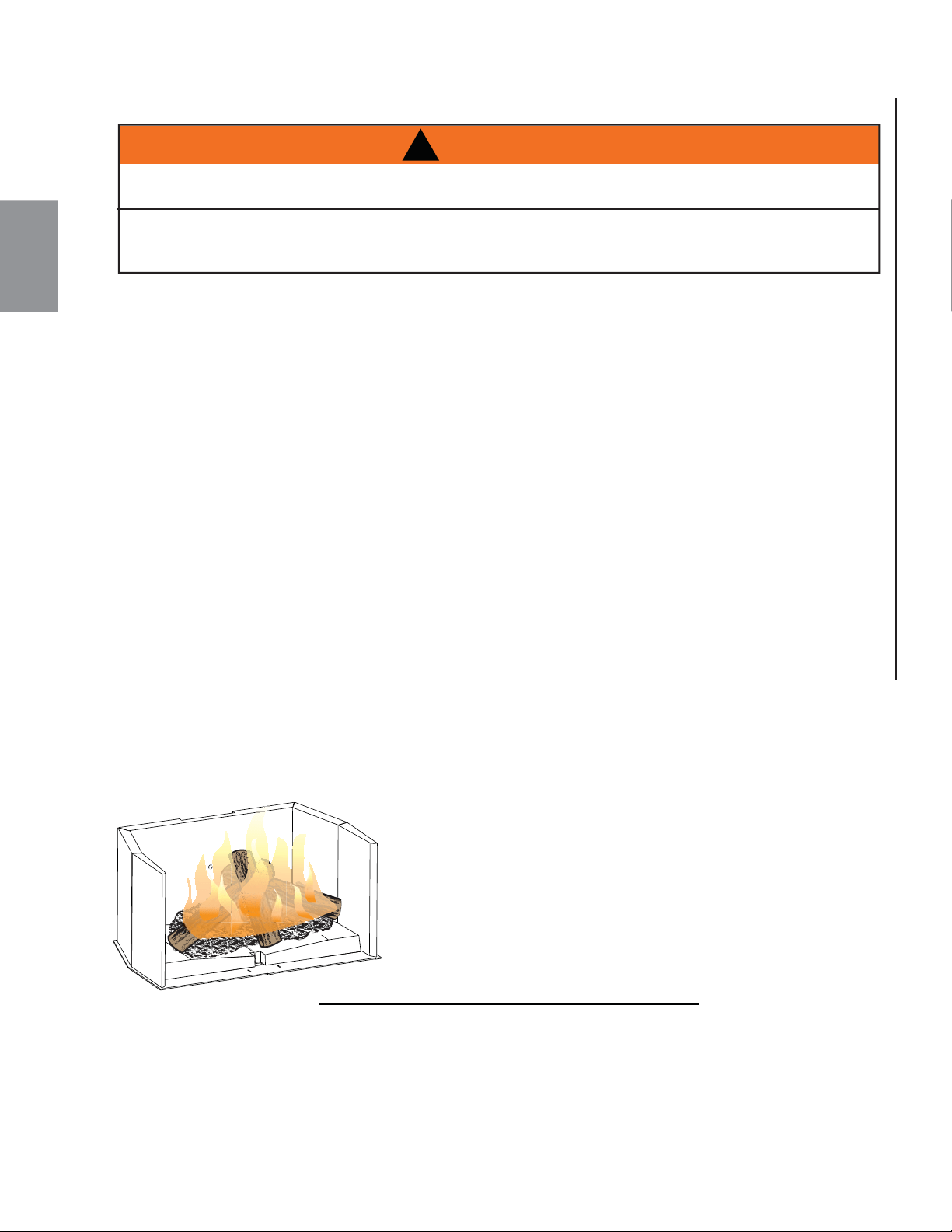
FR
W415-1476 / A / 10.12.16
66
93.1
Un feu éclair est un petit feu qui brûle rapidement quand vous
n’avez pas besoin de beaucoup de chaleur. Une fois que votre
bois d’allumage est bien allumé, chargez trois bûches par-dessus
de façon très lâche. Faites brûler avec le contrôle de combustion
pleinement ouvert ou à peine fermé.
!
AVERTISSEMENT
N’ENTREPOSEZ PAS LE BOIS À L’INTÉRIEUR DES DÉGAGEMENTS DE L’APPAREIL OU DANS
L’ESPACE REQUIS POUR LE RAVITAILLEMENT OU L’ENLÈVEMENT DES CENDRES.
BRÛLER DU BOIS VERT OU HUMIDE PEUT CAUSER DES ACCUMULATIONS EXCESSIVES DE
CRÉOSOTE. LORSQU’ALLUMÉE, ELLE PEUT CAUSER UN FEU DE CHEMINÉE ET UN INCENDIE
GRAVE POURRAIT S’ENSUIVRE.
On obtient une chaleur maximale pour un minimum de combustible (effi cacité maximale) quand le haut
de l’appareil sous la grille ornementale atteint des températures entre 500°F (260°C) et 600°F (315°C).
Les briques seront presque entièrement blanches et la vitre presque entièrement propre. Ceci est un bon
indicateur que votre appareil fonctionne effi cacement. Lorsque vous ne brûlez qu’une ou deux bûches,
l’appareil ne produira pas assez de chaleur ou le bois ne brûlera pas complètement. Il faut au moins trois
bûches pour arriver à avoir un lit de braises qui nourrira le feu.
Des bûches placées de façon lâche brûleront plus rapidement que celles placées serrées les unes contre les
autres. Le bois brûle de façon cyclique au lieu de fournir une chaleur constante. Il est donc préférable de
planifi er ces cycles en fonction de vos activités familiales de façon à ce que suffi samment de braises soient
disponibles pour allumer la charge suivante. Le soir, chargez votre appareil au moins une demi-heure avant de
vous coucher pour vous assurer que le feu soit suffi samment chaud pour fermer le contrôle de combustion
pour une combustion nocturne.
Ne brûlez que du bois bien sec avec moins de 20% d’humidité. Il produit plus de chaleur et moins de suie et
de créosote. Ne brûlez pas le bois qui a séjourné dans l’eau de mer; le contenu en sel peut produire un acide
qui gruge le métal. Lorsque vous rechargez l’appareil, ouvrez la porte lentement afi n d’éviter les refoulements
de fumée. Lorsque vous alimentez le feu, portez de longs gants protecteurs (gants pour BBQ). Puisque la
combustion se fait à l’avant, ces appareils sont propres et effi caces, mais ils deviennent aussi très chauds
et les gants sont alors très utiles. Gardez une petite pelle en acier à proximité; elle peut être utilisée comme
tisonnier ou pour enlever les cendres. N’entreposez pas le bois à moins de trois pieds (1 m) de l’appareil.
7.5 COMBUSTIBLE
7.6 ALLUMER UN FEU
7.6.1 FEU ÉCLAIR
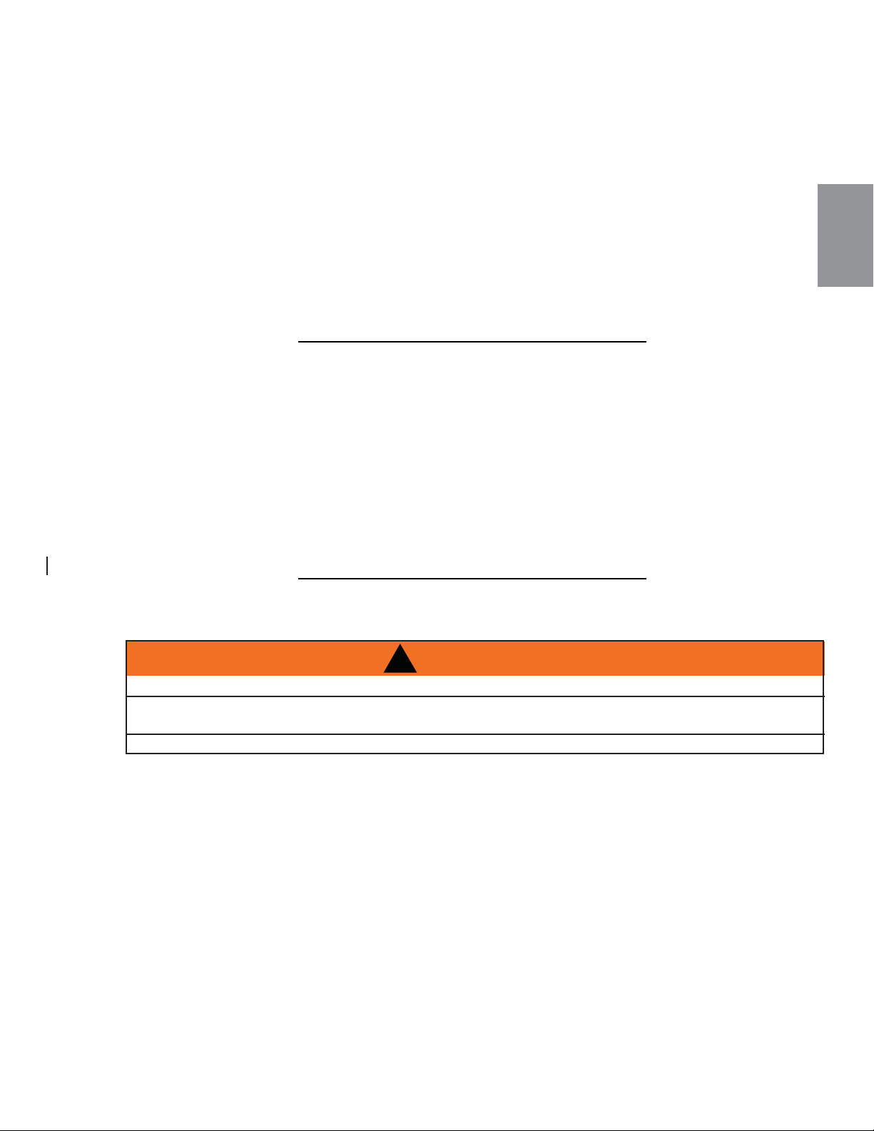
FR
W415-1476 / A / 10.12.16
67
7.6.2 FEU CONTINU
7.7 ENFUMAGE
82.1
Chargez vos bûches de dimension plus grande de façon compacte pour empêcher les fl ammes de s’infi ltrer
complètement. Après 30 minutes environ, selon la grosseur de la charge, fermez le contrôle de combustion en
vérifi ant que le feu ne se soit pas éteint.
NE SURCHAUFFEZ PAS L’APPAREIL!
Une surchauffe peut se produire :
A. en brûlant de grandes quantités de bois de dimension réduite, tel que des rebuts de bois de meuble, des
palettes ou du bois traité;
B. en brûlant vivement des grandes quantités de bois avec le contrôle de combustion à « HIGH » (entièrement
ouvert) pendant de longues périodes (une ou deux heures).
C. en faisant fonctionner l’appareil lorsque la porte de la chute à cendres est ouverte ou lorsque le joint
d’étanchéité de la porte principale est défectueux.
83.1A
Un appareil installé convenablement ne devrait pas
f
umer.
S
i le vôtre
f
ume, véri
fi
ez les points suivants :
• Est-ce que la cheminée a pu se réchauffer suffi samment?
• Est-ce que le passage de la fumée est bloqué soit dans la cheminée, soit dans le conduit de raccordement, soit
dans l’appareil?
• Est-ce que la pièce est trop hermétique et que la prise d’air comburant n’est pas raccordée sur l’extérieur? Es-
sayez avec une fenêtre partiellement ouverte.
• Est-ce que le fl ot de fumée est restreint par un tuyau horizontal trop long ou par un trop grand nombre de coudes?
• S’agit-il d’un tirage faible causé par une cheminée non hermétique, une cheminée extérieure froide, un diamètre
de cheminée trop grand, une cheminée trop courte ou trop près des arbres ou d’un toit plus élevé?
• Est la teneur en humidité du bois supérieure à 20%?
• Si équipé, est-ce que le bypass catalyseur a été fermé ou fermé prématurément?
!
AVERTISSEMENT
COUPEZ L’ALIMENTATION ÉLECTRIQUE AVANT DE PROCÉDER À L’ENTRETIEN DE L’APPAREIL.
L’APPAREIL PEUT ÊTRE CHAUD. N’EFFECTUEZ AUCUN ENTRETIEN JUSQU’À CE QUE L’APPAREIL
SOIT REFROIDI.
N’UTILISEZ PAS DE NETTOYANTS ABRASIFS.
Afi n de prévenir les accumulations de suie et de créosote, vérifi ez votre cheminée et le conduit de
raccordement toutes les semaines jusqu’à ce qu’une fréquence de nettoyage sécuritaire soit établie.
Si les accumulations sont excessives, débranchez l’appareil et nettoyez-le ainsi que la cheminée. Vous
pourriez faire appel aux services d’un ramoneur professionnel pour nettoyer l’appareil et la cheminée; ils
doivent être nettoyés au moins une fois l’an ou aussi souvent que nécessaire.
- Inspecter les tuyaux d’air secondaire.
- Enlevez les défl ecteurs en fi bre et nettoyez au-dessus une fois par année. Remplacez les briques brisées.
- Inspecter et remplacer toutes les joints d’étanchéité, si nécessaire.
- Démonter, nettoyer et lubrifi er l’assemblage du poignée du porte.
8.0 ENTRETIEN
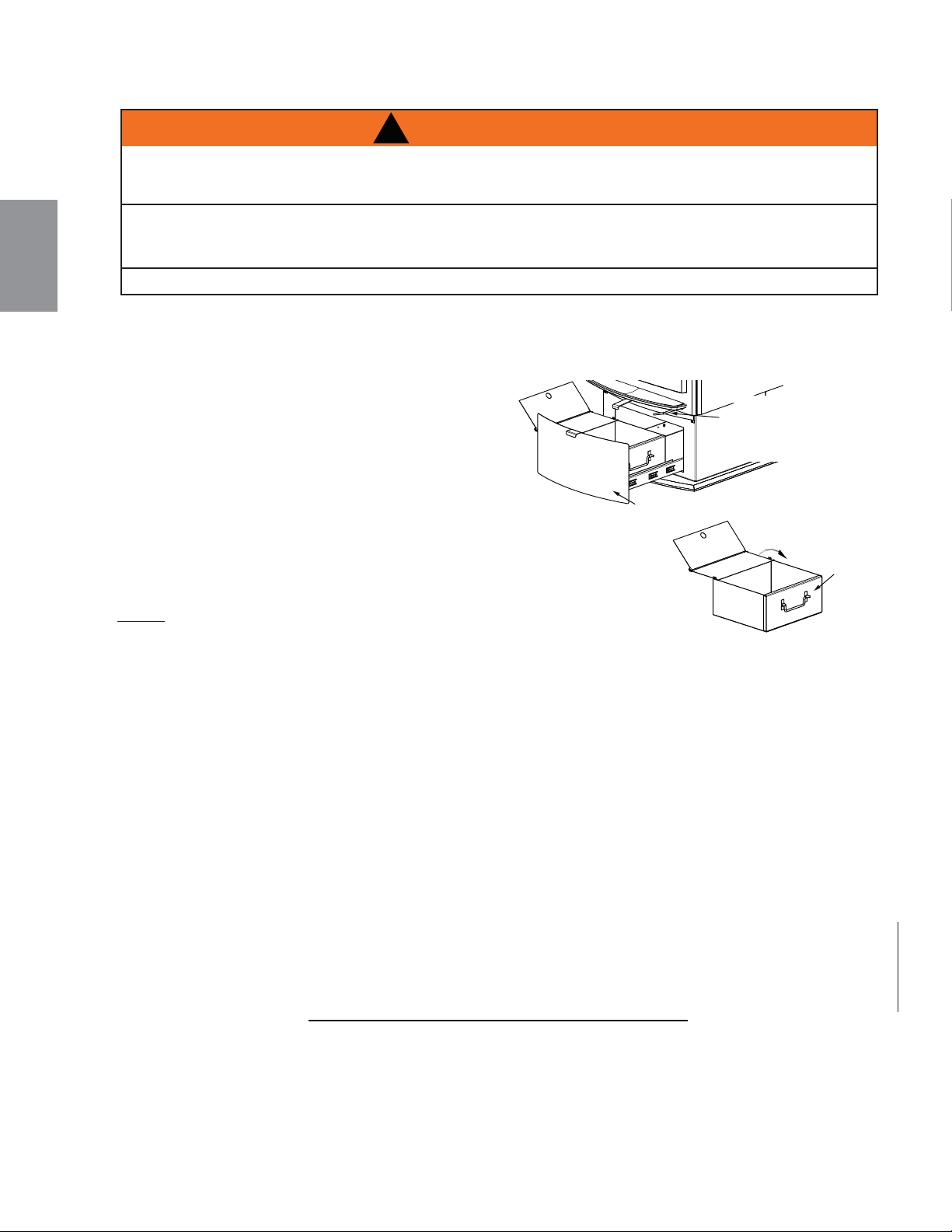
FR
W415-1476 / A / 10.12.16
68
8.1 ENLÈVEMENT DES CENDRES
Laissez les cendres s’accumuler sur une épaisseur de deux ou trois pouces (50.8mm - 76.2mm) sur le plancher de
la chambre de combustion; elles ont tendance à se consumer. Une fois que le feu s’est éteint et que les cendres se
sont refroidies, enlevez toutes les cendres excédentaires, mais laissez une épaisseur d’un pouce (25.4mm) sur le
plancher de la chambre de combustion pour aider à conserver un lit de braises chaudes.
Pour utiliser votre tiroir à cendres, tirez la poignée de la
chute à cendres, puis tournez-la de 90° vers la gauche
pour ouvrir. Ratissez les cendres excédentaires dans
le tiroir à cendres. Fermez la chute à cendres en vous
assurant qu’il n’y a pas de braises ou d’objets qui
empêchent le couvercle ou la chute à cendres de fermer.
Ceci engendre des risques qui pourraient causer un feu de
cheminée ou un incendie, ainsi que des dommages internes à l’appareil ou
la décoloration de la porte plaquée or (les fi nis plaqués ne sont pas couverts par
la garantie). Pour vous assurer que la chute à cendres est complètement fermée,
assurez-vous que la porte se ferme avec un bruit sec, délogeant ainsi ce qui pourrait
être coincé dans l’ouverture.
NOTE: ASSUREZ-VOUS QUE LE CENDRIER EST COMPLÈTEMENT REFOIDIT
AVANT D’ENLEVER LE TIROIR DE CENDRE.
Tirer le tiroir de cendre en avant pour ouvrir, ceci gagne l’accès au cendrier. Enlever le cendrier par élevant
à la côté gauche ou au côté droite du tiroir de cendre.Temporairement placer le cendrier sur une surface
incombustible et fermer le couvercle de cendrier. Enlever le cendrier et éliminer les cendres en toute sécurité.
Avant de réinstaller le cendrier assurez-vous que le couvercle de cendrier est OUVERT.Placer le cendrier dans
le tiroir de cendre et puis fermer le tiroir de cendre.
NE FAITES JAMAIS FONCTIONNER VOTRE APPAREIL QUAND LA CHUTE À CENDRES EST ENTROUVERT
OU OUVERTE.
COUVERCLE
DE CENDRIER
POUR OUVRIR:
TIRER ET TOURNER
POUR FERMER:
TOURNER AUX
DIRECTION OPPOSÉES
TIROIR DE
CENDRES
CENDRIER
8.2 FORMATION ET ENLÈVEMENT DE LA CRÉOSOTE
!
AVERTISSEMENT
L’ÉLIMINATION CORRECTE DES CENDRES CAUSE DES INCENDIES. NE JETEZ PAS LES CENDRES
DANS DES BOÎTES EN CARTON, NE LES JETEZ PAS DANS LA COUR ET NE LES ENTREPOSEZ PAS
DANS UN GARAGE.
SI VOUS UTILISEZ UN ASPIRATEUR POUR NETTOYER LES CENDRES, ASSUREZ-VOUS QUE CES
DERNIÈRES SOIENT ENTIÈREMENT REFROIDIES. L’UTILISATION D’UN ASPIRATEUR POUR
NETTOYER LES CENDRES CHAUDES POURRAIT OCCASIONNER UN INCENDIE DANS L’ASPIRATEUR.
NE FAITES JAMAIS FONCTIONNER L’APPAREIL AVEC LE COUVERCLE DE LA GRILLE RETIRÉ (SI APPLICABLE).
84.1A
Lorsque le bois brûle lentement, il produit du goudron et autres vapeurs organiques qui, se combinant à la
vapeur d’eau évacuée, forment la créosote. Ces vapeurs se condensent dans le conduit relativement froid
de la cheminée d’un appareil brûlant lentement. Par conséquent, le résidu de créosote accumule sur dans le
conduit. Lorsqu’elle prend feu, la créosote produit un feu extrêmement chaud.
Inspectez votre cheminée pour des accumulations de créosote chaque deux mois pendant le saison de
chauffage pour déterminer si une accumulation de créosote à former.
Si l’accumulation est excessive nettoyez la cheminée pour réduire une feu du chiminée.

FR
W415-1476 / A / 10.12.16
69
8.3 FEU DE CHEMINÉE OU FEU HORS CONTRÔLE
85.1
Des feux hors contrôle peuvent être causés par les trois facteurs suivants :
• L’utilisation d’un combustible inapproprié ou de morceaux de bois trop petits qui, normalement,
auraient été utilisés comme bois d’allumage.
• Une porte laissée entrouverte trop longtemps créant des températures extrêmes lorsque l’air est
entraîné précipitamment par la porte ouverte.
• Faire fonctionner l’appareil avec le couvercle de la chute à cendres mal installé.
SOLUTIONS :
• Ne brûlez pas de bois traité ou transformé, de charbon, de charbon de bois, de papier de couleur ou
de carton.
• Faites attention de ne pas surchauffer l’appareil en laissant la porte ouverte trop longtemps après
l’allumage initial. Un thermomètre sur le conduit de raccordement ou sur le dessus de l’appareil serait
utile.
• Faites toujours fonctionner l’appareil avec le couvercle de chute à cendres bien installé.
EN CAS DE FEU DE CHEMINÉE :
• Ayez un plan d’évacuation bien compris de tous et désignez un lieu de rassemblement à l’extérieur.
Préparez-vous à évacuer les lieux pour assurer la sécurité de chacun.
• Fermez la prise d’air de l’appareil.
• Appelez votre service d’incendie. Ayez un extincteur sous la main. Contactez les autorités locales pour
savoir quoi faire en cas de feu de cheminée.
• Après que le feu de cheminée est éteint et avant d’allumer un autre feu, nettoyez et inspectez
la cheminée pour des signes de détérioration ou des fi ssures. Vérifi ez également les matériaux
combustibles autour de la cheminée et du toit.
!
AVERTISSEMENT
UN FEU DE CHEMINÉE PEUT ENDOMMAGER VOTRE CHEMINÉE DE FAÇON PERMANENTE. POUR
RÉPARER CES DOMMAGES, VOUS DEVREZ REMPLACER LES COMPOSANTS ENDOMMAGÉS. LES
FEUX DE CHEMINÉE NE SONT PAS COUVERTS PAR LA GARANTIE À VIE LIMITÉE.
8.4 NETTOYAGE DE LA CHEMINÉE
86.1
La cheminée et l’appareil doivent être inspectés et nettoyés s’il y a lieu au moins une fois l’an.
En cas d’utilisation fréquente du chauffage au bois, le nettoyage de la cheminée doit être fait au besoin pour
éviter des feux de cheminée. Les systèmes d’évacuation des appareils à combustion contrôlée peuvent
nécessiter un nettoyage aussi fréquent qu’une fois par mois. Cependant, cette fréquence dépend des
habitudes de chauffage de la personne qui utilise l’appareil. À titre d’exemple, il est possible d’obstruer la
cheminée d’un appareil à combustible solide en quelques jours si l’appareil brûle lentement et que la cheminé
e
est froide.
NOTE : Les utilisateurs qui font toujours des feux chauds auront rarement d’importantes accumulations de
créosote dans la cheminée.
Lors du nettoyage de la cheminée, certains éléments doivent être considérés :
• Les outils appropriés doivent être utilisés, incluant une brosse spécialement conçue pour le ramonage
de la cheminée.
• Les conduits de raccordement, le registre et la cheminée doivent être nettoyés.
• La chambre de combustion et les défl ecteurs doivent être nettoyés au besoin.
• La cheminée doit être inspectée et réparée au besoin, de préférence par un ramoneur ou un maçon qualifi é.
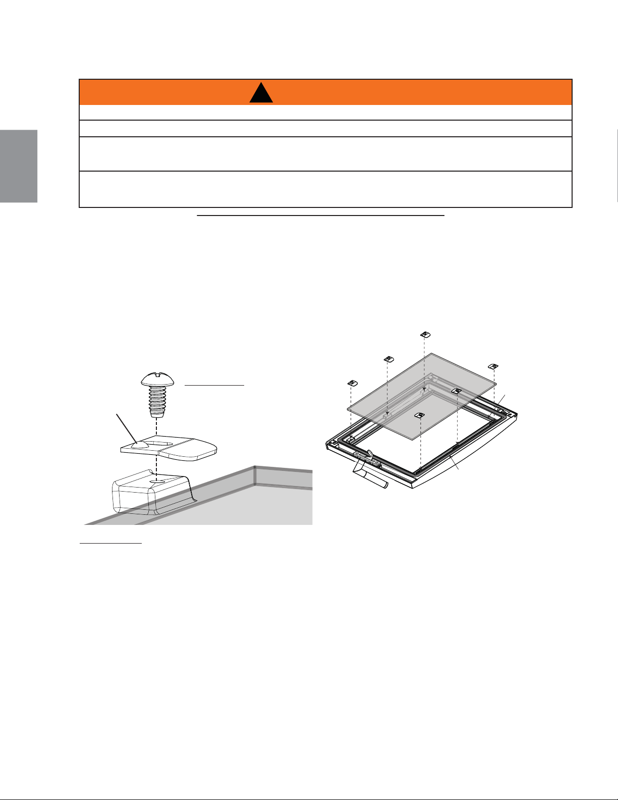
FR
W415-1476 / A / 10.12.16
70
8.5 REMPLACEMENT DE LA VITRE
REMARQUE: Pour remplacer la vitre voir la section « RECHANGES ».
JOINT D’ÉTANCHÉITÉ
DU VITRE
JOINT D’ÉTANCHÉITÉ
DU PORTE
!
AVERTISSEMENT
N’UTILISEZ PAS DE MATÉRIAUX DE SUBSTITUTION.
LA VITRE PEUT ÊTRE CHAUDE, NE TOUCHEZ PAS LA VITRE JUSQU’À CE QU’ELLE AIT REFROIDI.
USEZ DE PRUDENCE LORSQUE VOUS ENLEVEZ ET JETEZ DES DÉBRIS DE VERREOU DES
COMPOSANTS ENDOMMAGÉS. ASSUREZ-VOUS D’ASPIRER TOUS LES DÉBRIS DEVERRE À
L’INTÉRIEUR DE L’APPAREIL AVANT DE LE FAIRE FONCTIONNER.
NE FRAPPEZ PAS, NE CLAQUEZ PAS ET N’ÉGRATIGNEZ PAS LA PORTE VITRÉE. NE FAITES PAS
FONCTIONNER L’APPAREIL LORSQUE LA PORTE VITRÉE EST ENLEVÉE, FISSURÉE, BRISÉE OU
ÉGRATIGNÉE.
56.2
A. Quand l’appareil est refroidit enlever la porte, voir la section « ENLÈVEMENT ET INSTALLATION DE
LA PORTE ». Placer la porte sur une surface douce pour ne pas gratter la peinture.
B. Enlever les 6 vis (W570-0085) et puis les 6 supports du vitre (W500-0692). Enlever la vitre de
l’appareil.
C. Remplacer la joint d’étanchéité du porte et vitre, si nécessaire. Utilise le silicium rouge pout obtenir la
joint d’étanchéité en place.
D. Placer la vitre en position, fi xez avec les 6 supports de vitre, ne
serrez pas trop. Referez-vous à la section« ENLÈVEMENT
ET INSTALLATION DE LA PORTE » pour les instructions
d’installation de la porte.
BOSSE
IMPORTANT: ASSUREZ-
VOUS QUE LE BOSSE
SUR LE SUPPORT DE
VITRE FACE VERS L’HAUT,
COMME ILLUSTRÉE.
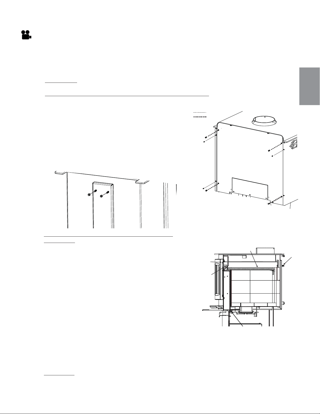
FR
W415-1476 / A / 10.12.16
71
8.6 COLLECTEUR D’AIR SECONDAIRE
À la fi n de chaque saison de chauffage, inspectez le tuyau d’air secondaire pour déceler des signes de
déformation ou de détérioration. Remplacez-le si nécessaire. À ce moment, vérifi ez également que le joint
d’étanchéité de la porte n’est pas usé ou desserré. Remplacez-le par une corde de ½ po (12,7mm) en
fi bre de verre à haute densité si nécessaire. L’écran et le joint du système autonettoyant situés à l’intérieur
de l’appareil, au-dessus de la porte devraient être inspectés et remplacés s’ils sont détériorés. Contactez
votre revendeur Napoléon pour le type et la taille spécifi que des matériaux nécessaires.
REMARQUE: Ne faites pas fonctionner l’appareil si le collecteur, l’écran du système autonettoyant
ou le défl ecteur en fi bre sont détériorés ou manquants.
Pour installer collecteur d’air secondaire suivre ces
instructions:
A. Repérez la fente à l’avant de la chambre de
combustion, comme illustré.
B. Insérez la patte du collecteur d’air secondaire dans
la fente mentionnée ci-dessus et faites pivoter le
collecteur d’air secondaire en position.
C.
Un nouveau joint DOIT être installé entre le collecteur
d’air secondaire et la chambre de combustion.
D. Insérez un des boulons pour maintenir le collecteur
d’air secondaire en place.
E. En travaillant à l’intérieur de la chambre de
combustion, prenez le deuxième boulon et installez-
le en position, en serrant légèrement la rondelle et l’écrou.
F. Retirez le premier boulon et réinstallez-le comme décrit précédemment à l’étape E. Serrez les écrous
et les boulons.
G. Réinstallez les défl ecteurs et les briques.
H. Pour réinstaller les écrans arrière et latéraux, référez-vous aux étapes A et B des instructions sur le
retrait.
REMARQUE: POUSSEZ LE DÉFLECTEUR ENTIÈREMENT VERS L’ARRIÈRE DE LA CHAMBRE DE
COMBUSTION, LAISSANT UN ESPACE MINIMAL DE 1 PO (25,4 MM) À L’AVANT. CECI PERMETTRA
AUX FUMÉES DE BIEN ÊTRE ÉVACUÉES DE LA CHAMBRE DE COMBUSTION.
Pour enlever le collecteur d’air secondaire suivre ces instructions:
A. Retirez les vis de fi xation des écrans latéraux, faites-
les glisser vers l’avant et retirez-les de l’appareil.
B. Retirez les vis de fi xation de l’écran arrière, puis
retirez l’écran de l’appareil.
C. Enlevez les briques arrière, puis retirez le défl ecteur.
D. Retirez les deux écrous et boulons de fi xation
du collecteur d’air secondaire; référez-vous à
l’illustration ci-dessous.
E. Retirez le collecteur d’air secondaire et joint
d’étanchéité.
ÉCRAN ET JOINT
D’ÉTANCHÉITÉ
DU SYSTÈME
AUTONETTOYANT
FENTE
COLLECTEUR D’AIR
SECONDAIRE
ÉCROU ET
BOULON (X2)
VUE DU CÔTÉ
A
B

FR
W415-1476 / A / 10.12.16
72
8.7 SOINS DE LA VITRE
8.8 SOINS DES PIÈCES PLAQUÉES
6.1
Si l’appareil est muni de pièces plaquées, vous devez enlever toutes traces de doigts ou autres marques
des surfaces plaquées avant d’allumer l’appareil pour la première fois. Utilisez un nettoyant à vitres ou du
vinaigre et un linge pour nettoyer. Si la surface plaquée n’est pas bien nettoyée avant le premier allumage de
l’appareil, elle risque de rester marquée en permanence. Une fois que la surface plaquée aura chauffé, les
traces de doigts et le gras n’affecteront plus la surface et très peu d’entretien sera requis; vous n’aurez qu’à
l’essuyer au besoin. Une combustion prolongée à haute température avec la porte ouverte peut causer une
décoloration des pièces plaquées.
NOTE: L’emballage de protection sur les pièces plaquées s’enlève mieux lorsque l’assemblage est
à température ambiante ou lorsqu’il est chauffé avec un séchoir à cheveux ou une autre source de
chaleur similaire.
Si vous ne nettoyez pas les dépôts régulièrement, la vitre risque de
rester marquée en permanence. Normalement, un feu très chaud
maintiendra la vitre propre. Les raisons les plus fréquentes pour
lesquelles la vitre se salit sont: trop peu de combustible est utilisé pour
réchauffer suffi samment l’appareil, l’utilisation de bois vert ou humide,
le contrôle de combustion est trop fermé, créant une insuffi sance d’air
pour réaliser une combustion complète. S’il est nécessaire de nettoyer
la vitre, utilisez un linge doux avec un nettoyeur sans abrasif.
NE PAS NETTOYER LORSQU’ELLE EST CHAUDE! Nettoyez la vitre
avec un nettoyeur recommandé après les dix premières heures de
fonctionnement. Par la suite, nettoyez aussi souvent qu’il le faudra.
La vitre est très résistante, mais ne laissez pas de bois en combustion s’appuyer contre elle. Fermez toujours la porte
doucement. NE FORCEZ JAMAIS POUR LA FERMER!
Si la vitre devait fi ssurer pendant que le feu brûle, n’ouvrez pas la porte jusqu’à ce que le feu s’éteigne et n’utilisez
pas l’appareil jusqu’à ce que la vitre ait été remplacée par une nouvelle, disponible chez votre détaillant autorisé.
N’UTILISEZ PAS DE MATÉRIAUX SUBSTITUTS.
5.3
UNE SURFACE VITREE CHAUDE
PEUT CAUSER DES BRÛLURES.
LAISSER REFROIDIR LA SURFACE
VITREE AVANT D’Y TOUCHER.
NE PERMETTEZ JAMAIS A UN
ENFANT DE TOUCHER LA
SURFACE VITREE.
!
ATTENTION
5.5.1A
L’appareil est muni d’une 5mm en verre céramique Remplacez uniquement avec une pièce pour le foyer
disponible chez votre détaillant autorisé. N’UTILISEZ PAS DE MATÉRIAUX SUBSTITUTS.
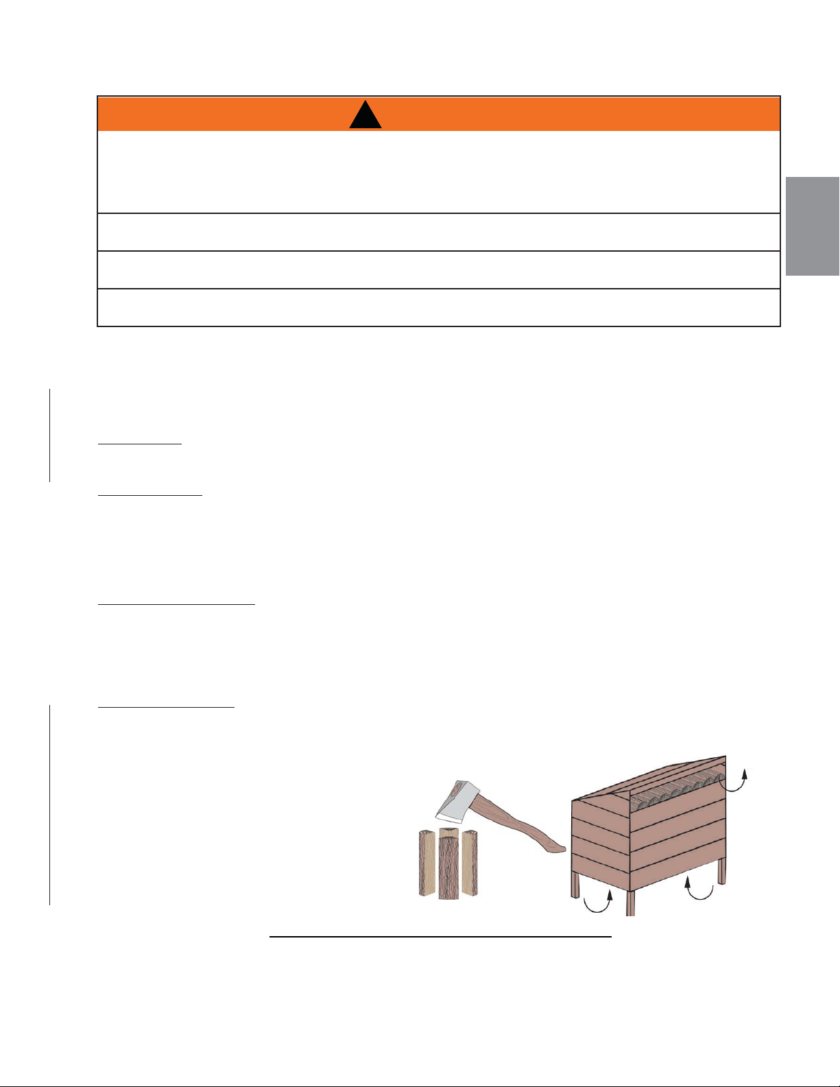
FR
W415-1476 / A / 10.12.16
73
8.9 BOIS
Lorsque vous chargez l’appareil, assurez-vous que les défl ecteurs est situé correctement. Pour assurer une
effi cacité maximale lorsque l’appareil est réchauffé, remplissez-le avec du bois jusqu’au haut de la porte de
chargement et brûlez en réglant à feu moyen-bas. Des briques presque entièrement blanches et une vitre
presque entièrement propre sont de bons indicateurs que votre appareil fonctionne effi cacement. Lorsque
vous ne brûlez que quelques bûches, l’appareil ne produira pas assez de chaleur ou le bois ne brûlera pas
complètement.
REMARQUE: Lorsque vous chargez l’appareil, assurez-vous de garder le combustible éloigné de la
vitre. Si des braises s’accumulent sur le rebord avant, elles pourraient tomber hors de l’appareil quand
vous ouvrez la porte.
TYPES DE BOIS
Le bois dur brûle aussi bien que le bois résineux dans cet appareil; par contre, le bois dur est plus dense, plus
lourd, brûle plus lentement et plus longtemps.
Les bûches artifi cielles obtenues par la compression de fi bre de bois 100% naturelle peuvent être utilisées
sans danger comme combustible. N’utilisez pas des bûches artifi cielles contenant des additifs comme de la
paraffi ne, de la cire, des liants, etc. Ne brûlez jamais plus de deux bûches artifi cielles à la fois.
CONTIENT D’HUMIDITÉ
Ne brûlez que du bois propre, non peint et bien sec. Il produit plus de chaleur et moins de suie et de créosote.
Le bois fraîchement coupé contient environ 50% d’humidité tandis qu’une fois séché, il n’en contient que 20%.
Quand le bois brûle, l’eau bout en consommant une partie de l’énergie qui aurait dû produire de la chaleur.
Plus le bois est humide, moins il y aura de chaleur et plus il y aura de créosote. Le bois sec a des craquelures
dans les extrémités.
STOCKAGE DE BOIS
Bois de chauffage doit être divisé et empilés de façon à permettre la circulation de l’air
complet et couverts au début du printemps pour être prêt pour la gravure de l’automne.
Bois de chauffage sec a des fi ssures dans la fi n du grain.
Coupez le bois de façon à ce qu’il puisse rentrer
horizontalement, de l’arrière vers l’avant, dans
l’appareil. Ceci facilite le chargement et il y aura
moins de risque que le bois roule sur la vitre.
Le combustible pour l’appareil ne doit pas être
entreposé à l’intérieur des dégagements minimaux
aux matériaux combustibles (matériau sensible à
la chaleur). N’ENTREPOSEZ JAMAIS DE BOIS
DANS LE COMPARTIMENT DU TIROIR À
CENDRES (s’il y a lieu).
!
AVERTISSEMENT
CIRCULATION D’AIR
CIRCULATION D’AIR
87.1E
CET APPAREIL A ÉTÉ CONÇU POUR BRÛLER DU BOIS NATUREL UNIQUEMENT. NE BRÛLEZ PAS DE BOIS TRAITÉS,
DE CHARBON DE BOIS, DE CHARBON, DE PAPIERS DE COULEUR, DE CARTONS, DE SOLVANTS NI DE DÉCHETS.
CET APPAREIL N’A PAS ÉTÉ TESTÉ AVEC UN ENSEMBLE DE BÛCHES À GAZ NON VENTILÉES. AFIN DE RÉDUIRE LE
RISQUE D’INCENDIE OU DE BLESSURE, N’INSTALLEZ PAS D’ENSEMBLE DE BÛCHES À GAZ NON VENTILÉES
DANS CET APPAREIL.
VOUS OBTENEZ UNE MEILLEURE EFFICACITÉ ET DES ÉMISSIONS PLUS FAIBLES AVEC DU BOIS DUR SÉCHÉ À
L’AIR QU’AVEC DU BOIS RÉSINEUX OU VERT, OU DES BOIS DURS FRAÎCHEMENT COUPÉS.
BRÛLER DU BOIS VERT OU HUMIDE PEUT CAUSER DES ACCUMULATIONS EXCESSIVES DE CRÉOSOTE.
LORSQU’ALLUMÉE, ELLE PEUT CAUSER UN FEU DE CHEMINÉE ET UN INCENDIE GRAVE POURRAIT S’ENSUIVRE.
N’ENTREPOSEZ PAS LE BOIS À L’INTÉRIEUR DES DÉGAGEMENTS DE L’APPAREIL OU DANS L’ESPACE REQUIS POUR
LE RAVITAILLEMENT OU L’ENLÈVEMENT DES CENDRES.
CIRCULATION
D’AIR

FR
W415-1476 / A / 10.12.16
74
9.0 RECHANGES
41.1C
Contactez votre détaillant pour les questions concernant les prix et la disponibilité des pièces de
rechange. Normalement, toutes les pièces peuvent être commandées chez votre détaillant autorisé.
POUR UN REMPLACEMENT DE PIÈCE SOUS GARANTIE, UNE PHOTOCOPIE DE LA
FACTURE ORIGINALE SERA REQUISE AFIN DE POUVOIR HONORER LA DEMANDE.
Lorsque vous commandez des pièces, donnez toujours l’information suivante :
• Modèle et numéro de série de l’appareil
• Date d’installation de l’appareil
• Numéro de la pièce
• Description de la pièce
• Fini
PIÈCES, NUMÉRO DES PIÈCES ET SI’IL SOIT DISPONIBILITÉ PEUT CHANGER SANS PRÉAVIS.
PARTIES IDENTIFIÉES COMME GARNIE SERONT LIVRÉS DANS 2 À 5 JOURS POUR LA
PLUPART DES DESTINATIONS DE LIVRAISON.
PIÈCES NON IDENTIFIÉES QUE STOCKÉS SERONT LIVRÉS DANS UN DÉLAI DE 2 À 4
SEMAINES POUR LA PLUPART DES CAS.
PIÈCES IDENTIFIÉES COMME « SO » SONT COMMANDE SPÉCIALE ET PEUVENT PRENDRE
JUSQU’À 90 JOURS POUR LA LIVRAISON.
OMETTRE DE POSITIONNER LES PIÈCES CONFORMÉMENT À CE MANUEL OU D’UTILISER UNIQUEMENT DES
PIÈCES SPÉCIFIQUEMENT APPROUVÉES POUR CET APPAREIL PEUT CAUSER DES DOMMAGES MATÉRIELS
OU DES BLESSURES CORPORELLES.
!
AVERTISSEMENT
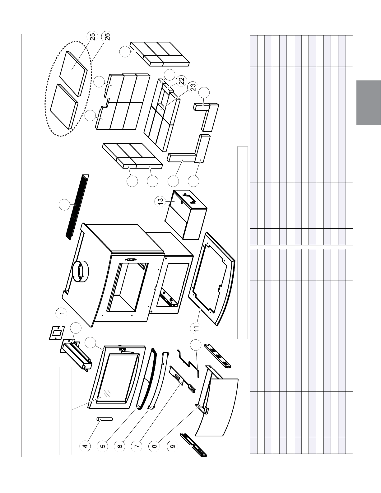
FR
W415-1476 / A / 10.12.16
75
9.1 VUE D’ENSEMBLE DU S1
1
11
18
2
4
8
13
12
3
9
10
5
6
17
16
19
24
22
15
23
20
25
7
14
21
1
11
25
2
4
8
13
12
3
9
10
5
6
17
16
18
23
21
15
22
19
24
7
14
20
S1
OVERVIEW
1 W290-0219
2 W432-0144
3 W010-3194 L’ASSEMBLAGE DU PORTE
4 W325-0081 MANCHON DU PORTE
5 W135-0238-SER LÈVRE DE CENDRES
6 W200-0415-SER COUVERCLE DU CENDRIER
7 W010-3094 CONTRÔLE D’AIR
8 W010-3043 TIROIR DU CENDRIER
9 W610-0010 CURSEURS DU TIROIR
10 W325-0017 POIGNÉE DU ASHWEL
L
11 W495-0048-SER BASE DU PIÉDESTA
L
12 W200-0414-SER CAPOT DE PROTECTION ARRIÈRE
13 W010-1534 CENDRIER
14 W090-0003 BRIQUE (1.25" x 4.5" x 4.5")
15 W090-0001 BRIQUE (1.25" x 4.5" x 9")
16 W090-0018 BRIQUE (1.25" x 2.25" x 9")
17 W090-0002 BRIQUE (1.25" x 3" x 9")
18
19
20
21
22
23
24
25
1826
OUI
OUI
W090-0207 (CG) BRIQUE ENTAILLÉES (1.25" x 4.5" x 9")
W090-0208 (CD) BRIQUE ENTAILLÉES (1.25" x 4.5" x 9")
W090-0184 BRIQUE (1.25" x 4.5" x 8.25")
W090-0166 BRIQUE (1.25" x 3" x 9")
W090-0017 BRIQUE (1.25" x 1.5" x 4.5")
W090-0016 BRIQUE (1.25" x 2.5" x 4.5")
W090-0216 BRIQUE (1.25" x 1.75" x 4.75")
W018-0077 SUPPORT DE BRIQUE
W010-3560 TROUSSE DE SUPPORTS DE BRIQUE
26
OUI
OUI
CES ARTICLES PEUT DIFFÉRER DE CELLE ILLUSTRÉ
POUR LES PIÉCES DE REMPLACEMENT
VOIR "L’ASSEMBLAGE DE LA PORTE”
RÉF. PART NO. DESCRIPTION DESCRIPTIONEN STOCK EN STOCKRÉF. PART NO.
COLLECTEUR
JOINT D’ÉTANCHÉITÉ DU COLLECTEUR
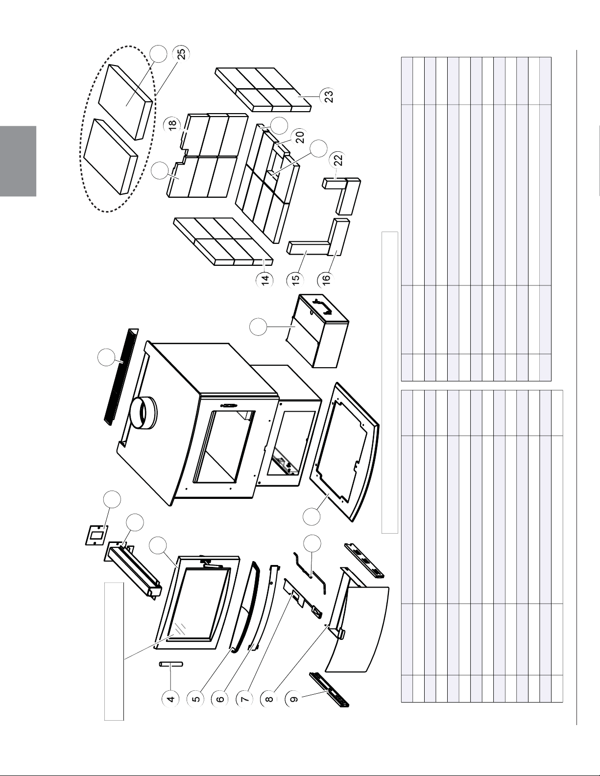
FR
W415-1476 / A / 10.12.16
76
1
8
2
11
12
4
7
10
6
3
5
9
18
16
13
20
15
19
14
22
21
24
23
1
8
2
11
12
4
7
10
6
3
5
9
17
16
13
19
15
18
14
21
20
23
22
1824
1825
S4 OVERVIEW
1
W290-0219
2
W432-0142
3
W010-3194
4
W325-0081
5
W135-0238-SER
6
W200-0415-SER
7
W010-3098
8
W010-3043
9
W610-0010
10
W325-0017
11
W495-0048-SER
12
W200-0414-SER
13
W010-1534
14
W090-0001
15
W090-0018
16
W090-0002
17
18
W090-0207
19
W090-0208
20
W090-0166
21
W090-0017
22
W090-0016
23
W090-0216
24
W090-0184
25
W018-0078
W010-3561
OUI
OUI
OUI
POUR LES PIÉCES DE REMPLACEMENT
VOIR "L’ASSEMBLAGE DE LA PORTE”
CES ARTICLES PEUT DIFFÉRER DE CELLE ILLUSTRÉ
RÉF.
PART NO.
DESCRIPTION
DESCRIPTION
EN STOCK
EN STOCK
RÉF.
PART NO.
L’ASSEMBLAGE DU PORTE
MANCHON DU PORTE
LÈVRE DE CENDRES
COUVERCLE DU CENDRIER
CONTRÔLE D’AIR
TIROIR DU CENDRIER
CURSEURS DU TIROIR
POIGNÉE DU ASHWELL
BASE DU PIÉDESTAL
CAPOT DE PROTECTION ARRIÈRE
CENDRIER
COLLECTEUR
JOINT D’ÉTANCHÉITÉ DU COLLECTEUR
SUPPORT DE BRIQUE
TROUSSE DE SUPPORTS DE BRIQUE
BRIQUE (1.25" x 4.5" x 9")
BRIQUE (1.25" x 2.25" x 9")
BRIQUE (1.25" x 3" x 9")
(CG) BRIQUE ENTAILLÉES (1.25" x 4.5" x 9")
(CD) BRIQUE ENTAILLÉES (1.25" x 4.5" x 9")
BRIQUE (1.25" x 4.5" x 8.25")
BRIQUE (1.25" x 3" x 9")
BRIQUE (1.25" x 1.5" x 4.5")
BRIQUE (1.25" x 2.5" x 4.5")
BRIQUE (1.25" x 1.75" x 4.75")
9.2 S4 OVERVIEW
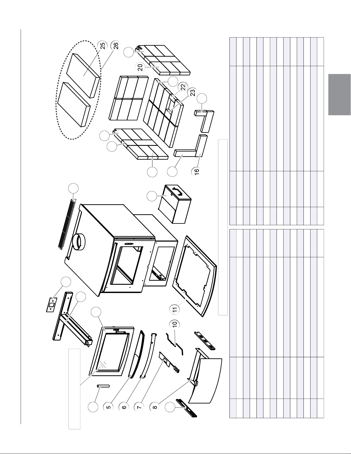
FR
W415-1476 / A / 10.12.16
77
26 W010-3562
7
11
1
8
10
5
2
6
4
12
3
13
9
18
20
16
17
15
22
14
21
23
25
24
7
11
1
8
10
5
2
6
4
12
3
13
9
18
21
16
17
15
23
14
22
24
19
20
S9 OVERVIEW
1 W290-0228
2 W432-0130
3 W010-3194
4 W325-0081
5 W135-0238-SER
6 W200-0415-SER
7 W010-3095
8 W010-3043
9 W610-0010
10 W325-0017
11 W495-0049
12 W200-0414-SER
13 W010-1534
14 W090-0015 BRIQUE (1.25" x 4.5" x 9")
15 W090-0018 BRIQUE (1.25" x 2.25" x 9")
16 W090-0002 BRIQUE (1.25" x 3" x 9")
17 W090-0003 BRIQUE 1.25" x 4.5" X 4.5")
18 W090-0207 (CG) BRIQUE ENTAILLÉES (1.25" x 4.5" x 9")
19
20 W090-0166 BRIQUE (1.25" x 3" x 9")
21 W090-0017 BRIQUE (1.25" x 1.5" x 4.5")
22 W090-0016 BRIQUE (1.25" x 2.5" x 4.5")
23 W090-0216 BRIQUE (1.25" x 1.75" x 4.75")
24 W090-0184 BRIQUE (1.25" x 4.5" x 8.25")
25
W090-0208 (CD) BRIQUE ENTAILLÉES (1.25" x 4.5" X 9")
W018-0130
1825
1826
OUI
OUI
POUR LES PIÉCES DE REMPLACEMENT
VOIR "L’ASSEMBLAGE DE LA PORTE”
CES ARTICLES PEUT DIFFÉRER DE CELLE ILLUSTRÉ
RÉF. PART NO. DESCRIPTION DESCRIPTIONEN STOCK EN STOCKRÉF. PART NO.
L’ASSEMBLAGE DU PORTE
MANCHON DU PORTE
LÈVRE DE CENDRES
COUVERCLE DU CENDRIER
CONTRÔLE D’AIR
TIROIR DU CENDRIER
CURSEURS DU TIROIR
POIGNÉE DU ASHWEL
L
BASE DU PIÉDESTA
L
CAPOT DE PROTECTION ARRIÈRE
CENDRIER
COLLECTEUR
JOINT D’ÉTANCHÉITÉ DU COLLECTEUR
SUPPORT DE BRIQUE
TROUSSE DE SUPPORTS DE BRIQUE
9.3 S9 OVERVIEW
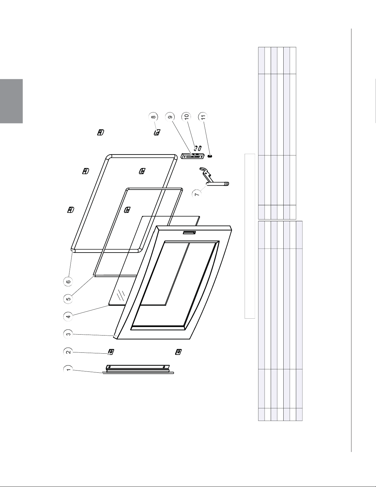
FR
W415-1476 / A / 10.12.16
78
8
6
5
4
1
2
3
11
9
10
8
6
5
4
1
2
3
11
9
10
1
W010-2947-SER
CHARNIÈRE DE PORTE
2
W500-0705
RETENUE DE CHARNIÈRE DE PORTE
3
W225-0313-SER
PORTE
4
W300-0168-SER
VITRE DU PORTE
5
W562-0070
TROUSSE DU JOINT D’ÉTANCHÉITE DU VITRE (1/4" DIA.)
6
W562-0071
TROUSSE DU JOINT D’ÉTANCHÉITE DU PORTE (1/2" DIA.)
7
W010-3078-CH4HF
POIGNÉE DU PORTE
8
W500-0709-SER
RETENUE DU VITRE
9
W060-0012-SER
BLOC DE LOQUET
10
W485-0052
GOUJON
11
W630-0024
RESSORT
77
OUI
OUI
OUI
OUI
OUI
CES ARTICLES PEUT DIFFÉRER DE CELLE ILLUSTRÉ
RÉF.
PART NO.
DESCRIPTION
EN STOCK
RÉF.
PART NO.
DESCRIPTION
EN STOCK
9.4 S1, S4 & S9 DOOR ASSEMBLY
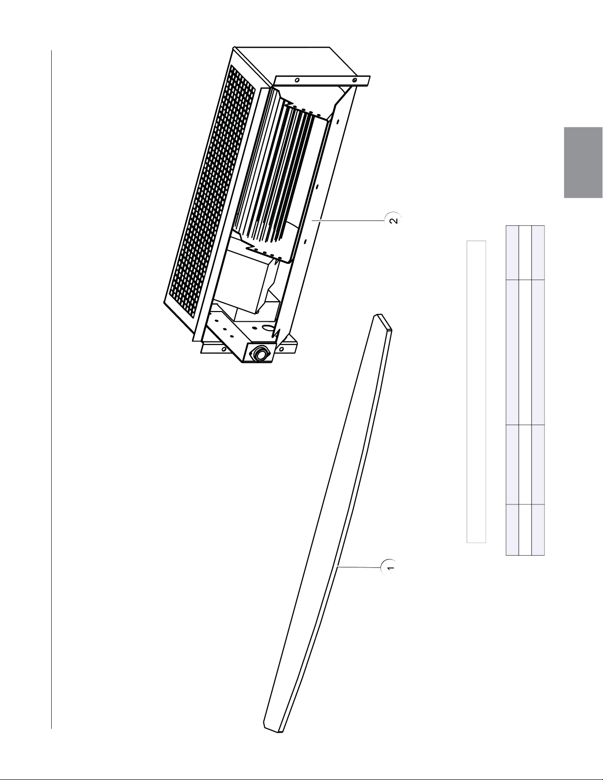
FR
W415-1476 / A / 10.12.16
79
2
1
2
1
1 W010-2944 GARNITURE DU PORTE
2 EP65 TROUSSE DEU SOUFFLERIE
RÉF. PART NO. DESCRIPTION EN STOCK
CES ARTICLES PEUT DIFFÉRER DE CELLE ILLUSTRÉ
10.0 S1, S4 & S9 ACCESSORIES

FR
W415-1476 / A / 10.12.16
80
11.0 GUIDE DE DÉPANNAGE
!
AVERTISSEMENT
COUPEZ L’ALIMENTATION ÉLECTRIQUE AVANT DE PROCÉDER À L’ENTRETIEN DE L’APPAREIL.
L’APPAREIL PEUT ÊTRE CHAUD. ATTENDEZ QU’IL SOIT REFROIDI AVANT D’EN FAIRE L’ENTRETIEN.
N’UTILISEZ PAS DE PRODUITS D’ENTRETIEN ABRASIFS.
LORSQUE VOUS VÉRIFIEZ DES CONNEXIONS, QUE VOUS INSTALLEZ DES FILS DE DÉRIVATION
(POUR EFFECTUER DES TESTS UNIQUEMENT) OU QUE VOUS REMPLACEZ DES COMPOSANTS,
DÉBRANCHEZ L’APPAREIL DU RÉCEPTACLE AFIN D’ÉVITER LES CHOCS ÉLECTRIQUES OU DES
DOMMAGES AUX COMPOSANTS.
PROBLÈME SOLUTIONS
Le feu ne s’allume pas. - Pas assez de bois d’allumage/de papier? Ajoutez-en.
- Pas assez d’air? Assurez-vous que le contrôle d’air est complètement
ouvert.
- Blocage d’air froid? Brûlez un morceau de papier journal pour créer un
tirage.
- Utilisez du bois bien sec avec de 20% d’humidité.
- Conduit obstrué? Inspectez la cheminée.
Présence de fumée
lorsque la porte est
ouverte.
- Blocage d’air froid? Brûlez un morceau de papier journal pour créer un
tirage.
- Tirage insuffi sant? Ajoutez des conduits.
- Laissez l’air se stabiliser avant d’ouvrir la porte.
- Assurez-vous que les défl ecteurs sont bien positionnés.
- Pression négative? Ouvrez une fenêtre située près de l’appareil.
Une odeur se dégage de
l’appareil.
- Cuisson de la peinture. Voir la section « INSTRUCTIONS GÉNÉRALES ».
L’appareil ne devient pas
suffi samment chaud.
- Le bois a plus de 20% d’humidité.
- Tirage insuffi sant? Ajoutez des conduits.
- Pas assez d’air? Assurez-vous que le contrôle d’air est complètement
ouvert. Assurez-vous que le contrôle d’air n’est pas obstruée.
Le bois brûle trop
rapidement.
- Le contrôle d’air doit possiblement être réduit.
- Assurez-vous que le couvercle de la chute à cendres est bien installé (s’il
en est muni).
- Vérifi ez que le joint d’étanchéité de la porte est bien hermétique.
- Le bois est peut-être extrêmement sec avec de 20% d’humidité.
Vitre sale. - Le contrôle d’air peut être trop fermé.
- Faites des feux plus chauds et plus petits.
- Utilisez du bois bien sec.
La souffl erie ne
fonctionne pas.
- L’appareil n’a peut-être pas atteint sa température.
- Assurez-vous que la souffl erie est bien branchée.
Le loquet de porte est
coincees
- L’enlevez loquet de la porte et appliquez un anti-grippant au les ressort.
Remontez.
FR
W415-1476 / A / 10.12.16
81
12.0 GARANTIE
NAPOLEON® warrants its products against manufacturing defects to the original purchaser only. Registering your warranty is not necessary. Simply
provide your proof of purchase along with the model and serial number to make a warranty claim. Provided that the purchase was made through an
authorized NAPOLEON® dealer your appliance is subject to the following conditions and limitations:
Warranty coverage begins on the date of original installation.
This factory warranty is non-transferable and may not be extended whatsoever by any of our representatives.
The wood appliance must be installed by an authorized service technician or contractor. Installation must be done in accordance with the installation
instructions included with the product and all local and national building and fi re codes.
EPA approved products, where incorrect fuel is used, will void the warranty.
This limited warranty does not cover damages caused by misuse, lack of maintenance, accident, alterations, abuse or neglect and parts installed from
other manufacturers will nullify this warranty.
This limited warranty further does not cover any scratches, dents, corrosion or discoloring caused by excessive heat, abrasive and chemical cleaners nor
chipping on porcelain enamel parts, nor any venting components used in the installation of the appliance.
This warranty extends to the repair or replacement of warranted parts which are defective in material or workmanship provided that the product has been
operated in accordance with the operation instructions and under normal conditions.
After the fi rst year, with respect to the President’s Lifetime Limited Warranty, NAPOLEON may, at its discretion, fully discharge all obligations with respect
to this warranty by refunding to the original warranted purchaser the wholesale price of any warranted but defective part(s).
After the fi rst year, NAPOLEON will not be responsible for installation, labour or any other costs or expenses related to the reinstallation of a warranted
part, and such expenses are not covered by this warranty.
Notwithstanding any provisions contained in the President’s Lifetime Limited Warranty, NAPOLEON’s responsibility under this warranty is defi ned as
above and it shall not in any event extend to any incidental, consequential or indirect damages.
This warranty defi nes the obligations and liability of NAPOLEON with respect to the NAPOLEON wood appliance and any other warranties expressed or
implied with respect to this product, its components or accessories are excluded.
NAPOLEON neither assumes, nor authorizes any third party to assume, on its behalf, any other liabilities with respect to the sale of this product.
NAPOLEON will not be responsible for: over-fi ring, downdrafts, spillage caused by environmental conditions such as rooftops, buildings, nearby trees,
hills, mountains, inadequate vents or ventilation, excessive venting confi gurations, insuffi cient makeup air, or negative air pressures which may or may not
be caused by mechanical systems such as exhaust fans, furnaces, clothes dryers, etc.
Any damages to appliance, combustion chamber, heat exchanger, plated trim or other component due to water, weather damage, long periods of
dampness, condensation, damaging chemicals or cleaners will not be the responsibility of NAPOLEON.
NAPOLEON reserves the right to have its representative inspect any product or part thereof prior to honouring any warranty claim.
All parts replaced under the President’s Limited Lifetime Warranty Policy are subject to a single claim.
During the fi rst 10 years NAPOLEON will replace or repair the defective parts covered by the lifetime warranty at our discretion free of charge. From 10
years to life, NAPOLEON will provide replacement parts at 50% of the current retail price.
All parts replaced under the warranty will be covered for a period of 90 days from the date of their installation.
The manufacturer may require that defective parts or products be returned or that digital pictures be provided to support the claim. Returned products are
to be shipped prepaid to the manufacturer for investigation. If a product is found to be defective, the manufacturer will repair or replace such defect.
Before shipping your appliance or defective components, your dealer must obtain an authorization number. Any merchandise shipped without authorization
will be refused and returned to sender.
Shipping costs are not covered under this warranty.
Additional service fees may apply if you are seeking warranty service from a dealer.
Warranty labour allowance is only for the replacement of the warranted part. Travel, diagnostic tests, shipping and other related charges are not covered
by this warranty.
2.2E
NAPOLEON products are manufactured under the strict Standard of the world recognized ISO 9001 : 2008 Quality Assurance
Certifi cate.
NAPOLEON products are designed with superior components and materials, assembled by trained craftsmen who take great
pride in their work. The complete appliance is again thoroughly inspected by a qualifi ed technician before packaging to ensure
that you, the customer, receives the quality product that you expect from NAPOLEON.
The following materials and workmanship in your new NAPOLEON wood appliance are warranted against defects for as long as
you own the appliance. This covers: combustion chamber, heat exchanger, ceramic glass (thermal breakage only), gold plated parts
against tarnishing, porcelainized enameled components, aluminum extrusion trims, vortex baffl es, ash drawer and iron castings.
Electrical (110V)
components and wearable parts are covered and NAPOLEON will provide replacement parts free of
charge during the fi rst year of the limited warranty. This covers:
blowers, thermal switch, switches, wiring, fi rebrick, stainless
steel baffl e retainer, secondary air tubes and gasketing. *
Labour related to warranty repair is covered free of charge during the fi rst year. Repair work, however, requires the prior approval of
an authorized company offi cial. Labour costs to the account of NAPOLEON are based on a predetermined rate schedule and any
repair work must be done through an authorized NAPOLEON dealer.
Parts such as fi rebricks and baffl es should routinely be removed by the operator as part of the regular service and therefore, any
warranty replacement of these parts does not qualify for any labour allowances.
* Construction of models vary. Warranty applies only to components included with your specifi c appliance.
NAPOLEON WOOD APPLIANCE PRESIDENT’S LIFETIME LIMITED WARRANTY
CONDITIONS AND LIMITATIONS
ALL SPECIFICATIONS AND DESIGNS ARE SUBJECT TO CHANGE WITHOUT PRIOR NOTICE DUE TO ON-GOING PRODUCT
IMPROVEMENTS. NAPOLEON IS A REGISTERED TRADEMARK OF WOLF STEEL LTD.

FR
W415-1476 / A / 10.12.16
82
13.0 HISTORIQUE D’ENTRETIEN
Date
43.1
Problèmes particuliersTravail effectuéNom du technicienDétaillant
Historique d’entretien Wolf Steel
Cet appareil doit être entretenu annuellement selon son usage.

FR
W415-1476 / A / 10.12.16
83
14.0 NOTES
44.1

"VUSFTQSPEVJUT/BQPMÏPO
®
'PZFST FODBTUSÏT t (SJMT BV DIBSCPO EF CPJT t 'PZFST BV HB[ t $BTDBEFT EFBV
1PÐMFTËCPJTt1SPEVJUT)7"$t'PZFSTÏMFDUSJRVFTt'PZFSTFYUÏSJFVSTt(SJMTËHB[EFRVBMJUÏ
'PZFST$IBVGGBHFFU$MJNBUJTBUJPO(SJMTDPNQPTF[
napoleonproducts.com
3PVUF5SBOTDBOBEJFOOF.POUSÏBM2VÏCFD)5"
/BQPMFPO3PBE#BSSJF0OUBSJP$BOBEB-.(
#BZWJFX%SJWF#BSSJF0OUBSJP$BOBEB-/:
.JMMFS%SJWF$SJUUFOEFO,FOUVDLZ64"