1
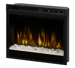
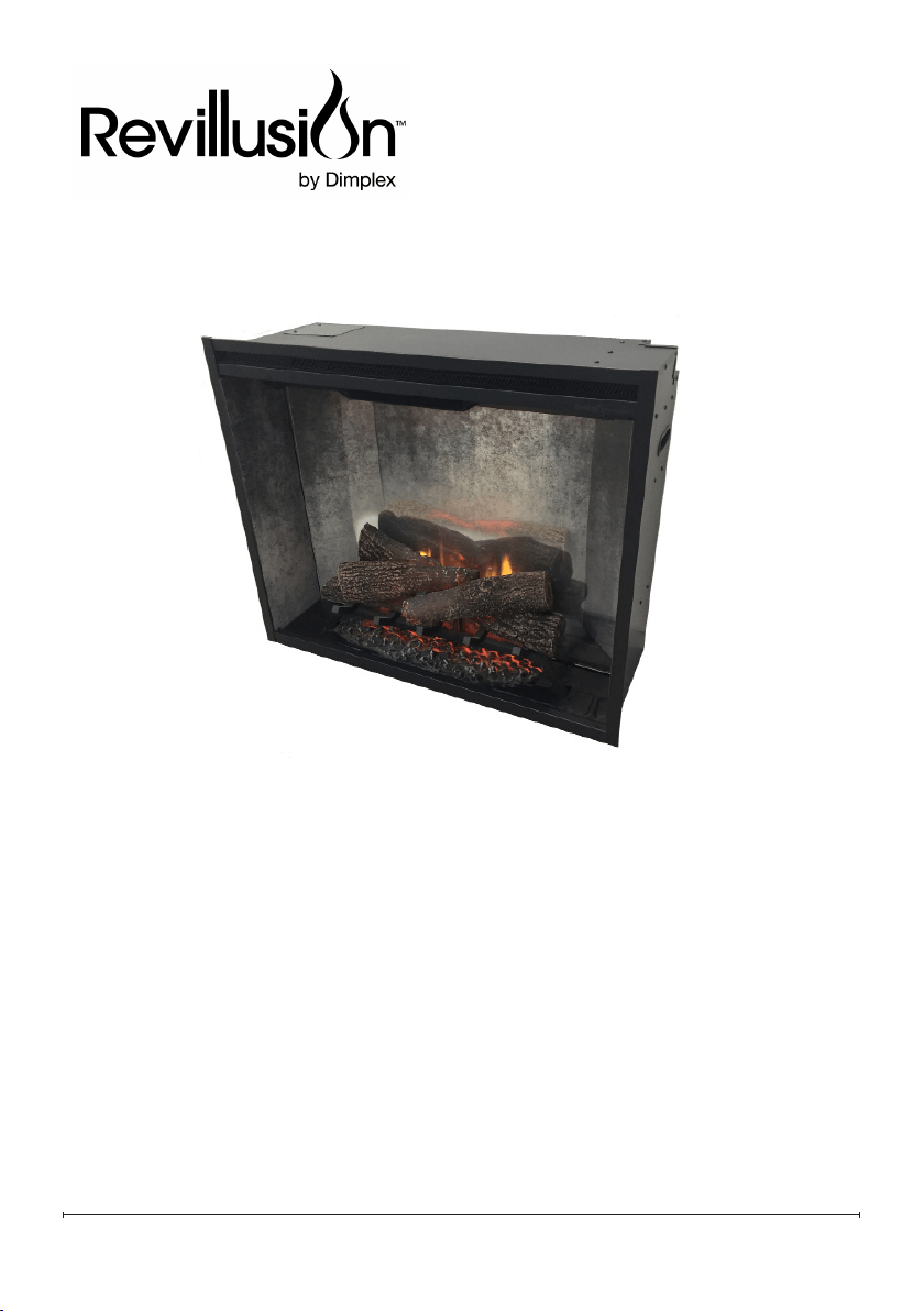
Revillusion™ Built-in Electric Firebox
Revillusion 30" Firebox (RBF30C-AU)
Revillusion 36" Firebox (RBF36C-AU)
Revillusion 42" Firebox (RBF42C-AU)
Owner’s Manual
IMPORTANT SAFETY INFORMATION: Read this manual rst before attempting
to install or use the Revillusion
™
Built-in Electric Firebox. Always comply with the
warnings and safety instructions contained in this manual to prevent personal
injury or property damage.
08/54541/0 (AU/NZ) Issue 3
OCN: 11823
2
Table of Contents
SAVE THESE INSTRUCTIONS
Conventions used in this manual:
!
NOTE: Procedures and techniques considered important enough to emphasize.
CAUTION: Procedures and techniques which, if not carefully followed, will result in
damage to the equipment.
WARNING: Procedures, precautions and techniques which, if not carefully followed,
will expose the user to the risk of re, serious injury, or death.
Welcome ..............................................................3
IMPORTANT INSTRUCTIONS ............................ 4
Specications ......................................................6
Installation ............................................................ 7
Operation ..............................................................9
Maintenance ......................................................12
3
Welcome
Thank you for purchasing a Revillusion™ Built-in Electric Firebox by Dimplex.
CAUTION: Read all instructions and warnings carefully before starting installation.
Failure to follow these instructions may result in a possible electric shock or re hazard
and will void the warranty.
NO NEED TO RETURN TO THE STORE
Questions with operation or assembly? Require Parts Information?
Product Under Manufacturer’s Warranty?
Please consult your warrenty card for our contact details.
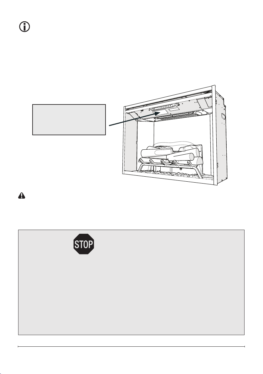
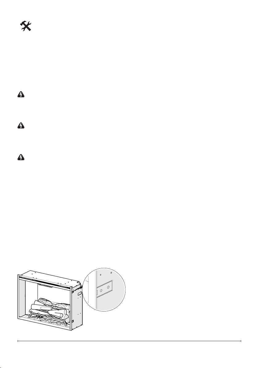
Rating Label

4
IMPORTANT INSTRUCTIONS
Read all instructions before using this appliance.
When using electrical appliances, basic precautions should always be
followed to reduce the risk of re, electrical shock and injury to persons,
including the following:
1. If the appliance is damaged, check with the supplier before installation
and operation.
2. Do not use outdoors.
3. Do not use in the immediate surroundings of a bath, shower or swimming
pool.
4. Do not locate the appliance immediately below a xed socket outlet or
connection box.
5. This appliance is not intended for use by persons (including children) with
reduced physical, sensory or mental capabilities, or lack of experience
and knowledge, unless they have been given supervision or instruction
concerning use of the appliance by a person responsible for their safety.
Clening and user maintaince shall not be made by children.
6. Children should be supervised to ensure that they do not play with the
appliance.
7. Children shall not turn on/off the appliance.
8. Do not use this appliance in series with a thermal control, a program
controller, a timer or any other device that switches on the heat
automatically, since a re risk exists when the appliance is accidentally
covered or displaced.
9. Ensure that furniture, curtains or other combustible material are positioned
no closer than 1 metre from the appliance.
10. In the event of a fault unplug the appliance.
11. Unplug the appliance when not required for long periods.
12. Although this appliance complies with safety standards, we do not
recommend its use on deep pile carpets or on long hair type of rugs.
13. The appliance must be positioned so that the plug is accessible.
14. If the supply cord is damaged it must be replaced by the manufacturer or
service agent or a similarly qualied person in order to avoid a hazard.
15. Keep the supply cord away from the front of the appliance.
5
IMPORTANT INSTRUCTIONS
WARNING: In order to avoid overheating, do not cover the
appliance. Do not place material or garments on the appliance,
or obstruct the air circulation around the appliance, for instance
by curtains or furniture, as this could cause overheating and a re
risk.
WARNING: In order to avoid a hazard due to inadvertent resetting
of the thermal cut-out, this appliance must not be supplied through an
external switching device, such as a timer, or connected to a circuit
that is regularly switched on and off by the utility.
CAUTION: Some parts of this product can become very hot and
cause burns. Particular attention has to be given where children and
vulnerable people are present.
WARNING: KEEP BATTERIES OUT OF REACH OF CHILDREN
1. Swallowing may lead to serious injury in as little as 2 hours or
death, due to the chemical burns and potential perforation of the
oesophagus.
2. If you suspect your child has swallowed or inserted a button battery
immediately call the 24-hour Poisons Information Centre on 13 11 26
(in Australia) or 0800 764 766 (in New Zealand) for fast, expert advice.
3. Examine devices and make sure the battery compartment is correctly
secured, e.g. that the screw or other mechanical fastener is tightened.
Do not use if the compartment is not secure.
4. Dispose of used button batteries immediately and safely. Flat
batteries can still be dangerous.
6
Specications
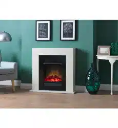
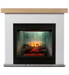
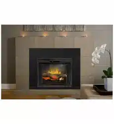
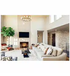
The Revillusion™ Built-in Electric Firebox offers an alternative to a wood or gas
fireplace. It can give your existing fireplace new life or transform a cabinet or media
center of your own into a stunning focal point.
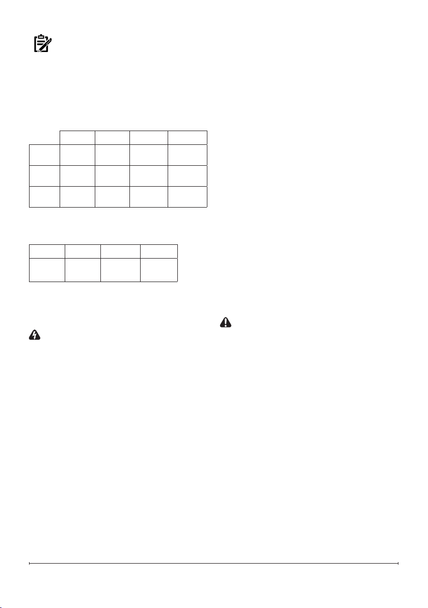
Dimensions
RBF30 RBF36 RBF36P RBF42
Width 31 1/8"
792 mm
37 1/8"
944 mm
37 1/8"
944 mm
43 1/4"
1098 mm
Height 26 5/8"
676 mm
26 5/8"
676 mm
31"
788 mm
31"
788 mm
Depth 12 1/8"
307 mm
12 1/8"
307 mm
12 1/8"
307 mm
12 1/8"
307 mm
Weight
RBF30 RBF36 RBF36P RBF42
50 lbs
22.7 kg
60 lbs
27.2 kg
65 lbs
29.5 kg
70 lbs
31.8 kg
Operation Temperature
-4
o
to 104
o
F (-20
o
to 40
o
C)
WARNING: Electrical outlet wiring must
comply with local building codes and other
applicable regulations to reduce the risk of
re, electric shock, or injury to persons.
NOTE: A 13Amp (EU) or 10 Amp(AU/
NZ) circuit is required. A dedicated circuit
is preferred, but not essential in all cases.
A dedicated circuit will be required if, after
installation, the circuit breaker trips or the
fuse blows on a regular basis when the
heater is operating. Additional appliances
on the same circuit may exceed the current
rating of the circuit breaker.
!
Unpacking the Unit
The unit comes packed with a protective
sheet covering the front of the unit. This
sheet is intended to prevent dust and
debris from entering during construction.
This sheet is designed so that it can be
partially removed to complete the wiring
and unpacking and can be reinstalled
until the final installation is complete.
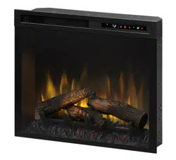
The log set was installed on the grate
and the grate permanently fixed to the
firebox at the factory.
Carefully remove the packaging from
around the log set. Make sure the wires
from the log set are connected securely
to the grate box.
CAUTION: The Realogs™ contain
LEDs to create a unique pulse and glow
effect. Handle the log set carefully. They are
fragile and can crack or break if dropped.
7
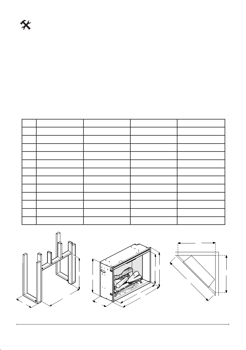
Installation
RBF30 RBF36 RBF36P RBF42
A 12 1/2" (318 mm) 12 1/2" (318 mm) 12 1/2" (318 mm) 12 1/2" (318 mm)
B 30 5/8" (778 mm) 36 5/8" (930 mm) 36 5/8" (930 mm) 42 5/8" (1083 mm)
C 26 3/16" (665 mm) 26 3/16" (665 mm) 30 5/8" (778 mm) 30 5/8" (778 mm)
D 25 3/4" (654 mm) 25 3/4" (654 mm) 30 1/4" (768 mm) 30 1/4" (768 mm)
E 12" (306 mm) 12" (306 mm) 12" (306 mm) 12" (306 mm)
F 29 3/8" (746 mm) 35 3/8" (898 mm) 35 3/8" (898 mm) 41 1/2" (1053 mm)
G 31 1/8" (792 mm) 37 1/8" (944 mm) 37 1/8" (944 mm) 43 1/4" (1098 mm)
H 22 3/4" (578 mm) 22 3/4" (578 mm) 27 1/4" (691 mm) 27 1/4" (691 mm)
I 26 5/8" (6764 mm) 26 5/8" (674 mm) 31" (788 mm) 31" (788 mm)
J 54 1/4" (1378 mm) 60" (1524 mm) 60" (1524 mm) 66 1/2" (1689 mm)
K 38 1/2" (978 mm) 42 1/2" (1080 mm) 42 1/2" (1080 mm) 47" (1194 mm)
L 38 1/2" (978 mm) 42 1/2" (1080 mm) 42 1/2" (1080 mm) 47" (1194 mm)
Rough-In Framing Dimensions Firebox Dimensions Rough-In Corner Dimensions
Framing
1. The Revillusion
TM
Built-in Electric
Firebox does not require any special
venting.
2. Rough in the framing opening.
Following the recommended framing
dimensions below.
!
NOTE: The materials used for the nished surround must be cut to precise dimensions
(dimensions B & C) as the 1/4" (0.6 cm) self trimming ange is only to create a nished
appearance.
G
F
I
H
E
D
J
K
L
C
B
A
8
Placement
This firebox is a zero clearance design,
with the exception of the top of the unit,
where any insulation and vapor barrier
should be placed a minimum of 2”
(5.1 cm) from the firebox.
DANGER!: High temperatures may
be generated under certain abnormal
conditions. Do not partially or fully cover or
obstruct the front of the rebox.
WARNING: All electrical heaters have
hot and arcing or sparking parts inside. Do
not use it in areas where gasoline, paint, or
flammable liquids are used or stored.
WARNING: The built-in electric firebox
must NOT be in direct contact with any
building vapor barrier or insulation.
1. Place the firebox into the framed
opening. Level with shims if
necessary.
2. From the inside of the unit, gently
remove the interior brick panels
(attached magnetically) and bent
out, up to 90°, to be flush with the
surrounding studs.
3. Attach the firebox to frame using four
mounting flanges on the sides of
firebox and suitable hardware.
Fixed Wiring
In some jurisdictions this appliance
is supplied without a plug this is to
comply with the local regulations. In
such instances this appliance must be
installed by a suitabily quailified installer
and the means for disconnection must
be incorporated in the fixed wiring in
accordance with the local wiring rules.
Installation
9
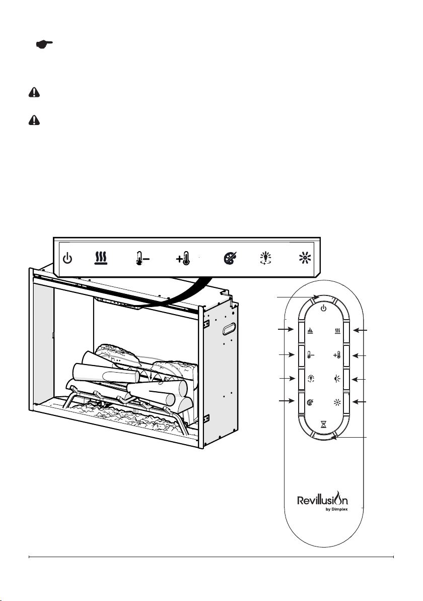
Operation
A B C D E F G
Touch Panel and Remote Controls
WARNING: The Revillusion
TM
Built-in Electric Firebox must be installed
properly before it is used.
CAUTION: Except for installation and cleaning described in this manual, an
authorized service representative should perform any other servicing.
The manual controls for the Revillusion
TM
Built-in Electric Firebox are located on
the front panel. Touch an icon to activate. The selected setting displays on the left
side of the panel.
A multi-function remote control also is provided. The remote control has a range of
approximately 30 ft (9 m). To operate correctly, the remote control must be pointed
toward the front of the built-in electric firebox.
H
A
C
I
E
J
B
F
G
D
10
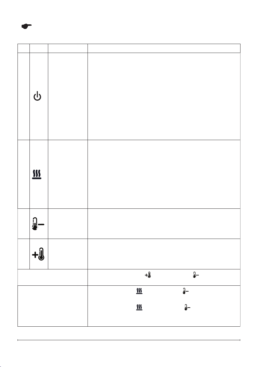
Operation
Icon Function Description
A
Power/
Standby
Press to activate the current standby state (On/Off).
• Standby State On
Press to turn everything Off. Press again to activate
the previous state.
• Standby State Off
Press to activate the previous state.
- If the flame effect was On, the previous heat setting
will be activated (On or Off).
- If the flame effect was Off, the previous heat setting
will be activated (High or Low).
Press again to turn everything Off.
B
Heat
• Heat On
Press to turn heat On (indicated by 1 short beep and
the icon appearing on the display). Displays current
heater temperature setting. Use the Temp Up/Down
icon to change the heater temperature setting.
• Heat Off
Press to turn heat Off (indicated by 1 short beep).
!
NOTE: After the heater is switched off, the fan will
continue on for 60 seconds before turning off.
C
Temp Down
Press multiple times to lower the heater temperature
in 1
0
F (1
0
C) increments. Displays current
temperature; lowest temperature is 41
0
F (5
0
C). This
feature is active whenever the heat is enabled.
D
Temp Up
Press multiple time to raise the heater temperature in
1
0
F (1
0
C) increments. Displays current temperature;
highest temperature is 99
0
F (37
0
C). This feature is
active whenever the heat is enabled.
Change Fahrenheit
(
0
F) to Celsius (
0
C)
Press both Temp+ ( ) and Temp– ( ) on the unit.
Heat Enable
Heat Disable
Hold both Heat ( ) and Temp– ( ), on the unit, for
2 seconds. Temperature displays on the screen.
Hold both Heat ( ) and Temp– ( ), on the unit,
for 2 seconds, when temperature is adjusted "---"
displays on the screen.
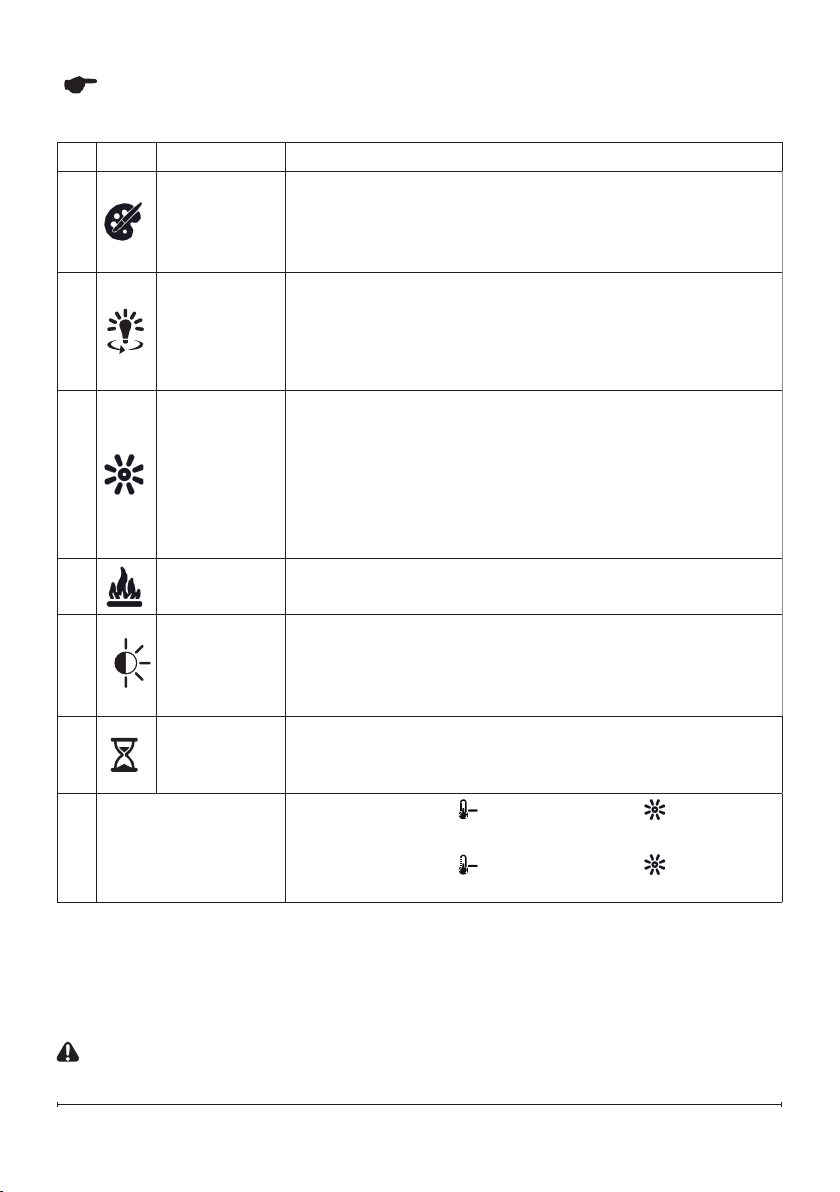
11
Operation
Icon Function Description
E
Color
Themes
Press multiple times to change the flame base colors
from Red to Blue to Off. (The first segment on the
display will change from "r" to "b" to blank) This
feature is active only when the flame effect is On.
F
360
o
Light
Press multiple times to change the LEDs on the sides
and back of the unit from Midnight mode to white to
yellow to red. (The middle segment on the display
will change through 0 - 3 respectively. This feature is
active only when the Flame is ON.)
G
Brightness
Press to change the LED lights from High to Low.
(The last segment on the display will change from
"H" to "L") The Realog
TM
LEDs remain On when the
heater is ON and the flame effect is Off.
!
NOTE: When the Light Sensor is activated, High
and Low ickering brightness settings are also available
(Flashing "H" and "L").
H
Flame
Press to light the log set and start the flame effect.
Press again to turn feature Off.
I
Light
Sensor
Press to activate (ALS ON) the ambient light sensor.
Press again to turn the sensor off (ALS OFF).
!
NOTE: The light sensor will adjust the brightness of the
replace based on the ambient light in the room.
J
Timer
Press multiple times to change the sleeper timer in
0.5 hr increments from 0.5 hr to 8.0 hr before turning
off. The remaining time on the sleep timer displays.
Control Lock
Control Unlock
Hold both Temp– ( ) and Brightness ( ), on the
unit, for 2 seconds to disable the manual controls.
Hold both Temp– ( ) and Brightness ( ), on the
unit, for 2 seconds to enable the manual controls.
Resetting the Temperature Cutoff Switch
Should the heater overheat, an automatic cut out will turn the heater off and it will
not come back on without being reset. It can be reset by disconnecting power at
the main electrical panel and waiting 5 minutes before plugging the unit back in.
CAUTION: If you need to con tinuously reset the heater, unplug the unit and call
technical support.
12
etc., the screen may collect dust
particles; these can be removed by
dusting lightly with a clean dry cloth.
To remove fingerprints or other marks,
clean the reflector screen damp cloth.
Never use abrasive cleaners. Dry the
screen completely with a lint free cloth
to prevent water spots.
Remote Battery Replacement
To replace the battery:
1. Push down on the battery cover
located on the back of the remote
control. Slide the battery cover
open.
2. Install 3V (CR2032) Lithium battery
in the battery holder. The positive
(+) side of the battery faces up.
3. Close the battery cover.
The old battery must be
recycled or disposed of
properly. Check with your
Local Authority or Retailer for
recycling advice in your area.
CAUTION: When transporting or storing
the heater and cord, keep in a dry place, free
from excessive vibration and store so as to
avoid damage.
Maintenance
General Maintenance
Inspect the built-in electric firebox
regularly, depending upon conditions,
and at a minimum yearly intervals.
Remove dust and clean the logs, grate,
and base as required.
WARNING: Disconnect power and
allow heater to cool before attempting any
maintenance or cleaning to reduce the risk
of re, electric shock, or injury.
CAUTION: Except for installation
and cleaning described in this manual, an
authorized service representative should
perform any other servicing.
Clean Logs and Base
The built-in electric firebox set should
not be operated with an accumulation
of dust or dirt on or in the firebox, as
this can cause a build up of heat and
eventual damage.
Dust and vacuum the firebox as needed.
Use a damp cloth and a mild detergent
to clean painted surfaces of the built-
in electric firebox. Never use abrasive
cleaners.
Clean Reflector Screen
The reflector screen is cleaned in the
factory during the assembly operation.
During shipment, installation, handling,
© Glen Dimplex Heating & Ventilation.
All rights reserved. Material contained in this publication may not be reproduced in whole
or part, without prior permission in writing of Glen Dimplex Heating & Ventilation.
Glen Dimplex Australia
8 Lakeview Drive,
Scoresby,
VIC 3179,
Australia
www.dimplex.com.au
Ph: 1300 556 816
Glen Dimplex New Zealand Pty Ltd.
38 Harris Road,
East Tamaki,
Auckland
New Zealand
www.dimplex.co.nz
Ph: 0800 666 2824