Loading ...
Loading ...
Loading ...
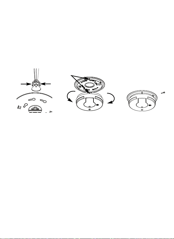
TAMPER RESIST LOCKING PIN: To make your smoke alarm tamper resistant, a
locking pin has been provided with your alarm. Using this pin will help deter
children and others from removing the alarm from trim ring. To use the pin,
insert it into the hole in the side of the alarm after the alarm has been installed
on the trim ring (see figure 8). NOTE: The tamper resist pin will have to be
removed in order to change the batteries. Use long nose pliers to pull the pin
out of the hole. It is now possible to remove the alarm from the trim ring.
After installation, TEST your alarm by pressing and holding the test/hush button
for several seconds. This should sound the alarm and activate the Safety Light.
4. OPERATION AND TESTING
OPERATION: The smoke alarm is operating once AC power is applied, fresh bat-
teries are installed and testing is complete. When the smoke alarm ionization
chamber senses products of combustion, the horn will sound a loud (85db) tem-
poral alarm until the sensing chamber is cleared of smoke particles.
SMART HUSH
TM
CONTROL: The “HUSH” feature has the capability of temporarily
desensitizing the alarm circuit for up to 8 minutes. This feature is to be used
only when a known alarm condition, such as smoke from cooking, activates the
alarm. The HUSH feature cannot be activated unless the smoke alarm is sound-
ing in the originating alarm mode. The smoke alarm is desensitized by pushing
the “ TEST / HUSH” button on the smoke alarm cover. If the smoke is not too
dense, the alarm will silence immediately. The red LED will illuminate for 1.5 sec-
onds every 8 seconds while in hush. This indicates that the alarm is in a tem-
porarily desensitized condition. The smoke alarm will automatically reset after
approximately 8 minutes and sound the alarm if particles of combustion are still
present. The “HUSH” feature can be used repeatedly until the air has been
cleared of the condition causing the alarm. Pushing the Test / Hush button on
the alarm will end the hush period.
FIGURE 6 FIGURE 7 FIGURE 8
To remove AC
connector,
squeeze
locking arms
and pull
Alignment
marks
Tamper Resist
Locking Pin
Install
Remove
Loading ...
Loading ...
Loading ...