Loading ...
Loading ...
Loading ...
Force-Air Propane Construction HeaterOperating Instructions and OwnerÊs Manual
6
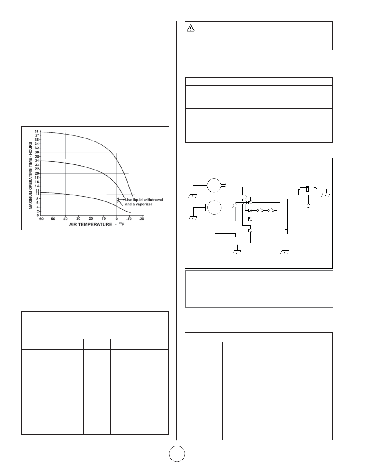
If any original wiring as supplied by the heater must be replaced,
it must be replaced with type AWG 105° C wire or its equivalent
except as indicated (*type SF2-200, **SGI 250° C).
170QFAVT - WIRING CHART
COLOR LENGTH FROM TO
White 7‰ Valve Terminal Block
Black 6‰ On/Off Switch Terminal Block
Red-(Hi-Temp) 16 1/2‰ High Limit Switch Valve
Red-(Hi-Temp) 16 1/2‰ High Limit Switch Terminal Block
Orange 11‰ Flame Control Spark Plug
(Ignition)
Green 7‰ Flame Control Ground
(Harness)
Red 7‰ Flame Control Terminal Block
(Harness)
White 6‰ Flame Control Terminal Block
(Harness)
Black 6‰ Flame Control Terminal Block
(Harness)
HOW MUCH HEAT DO I REQUIRE?
For economy, it is important to match input to that required. But
heat requirements often vary. For example, it usually takes a lot
more heat to get things warm than it does to keep them that way.
Likewise, outside air temperature usually changes during the day
so you may need more heat at night than you do in the daytime.
An approximation of the heat required can be found by using the
chart below.
Recommended Minimum Gauge
for Cord Extensions
Wire Gauge Chart A.W.G.
Name
Plate 120V Cord Length in Feet
Amps. 25 50 100 150
5-6 18 16 14 12
6-8 18 16 12 10
8-12 18 14 12 10
10-12 16 14 10 8
12-14 16 12 10 8
WARNING: When using a thermostat controlled heater,
its exit area should be protected from personnel and
warnings posted of sudden startup.
Cubic feet Temperature Rise Required (
o
F)*
of space to
be heated 20
o
30
o
40
o
50
o
5,000 14,000 20,000 27,999 34,000
7,000 19,000 28,000 38,000 47,000
10,000 27,000 40,000 54,000 67,000
15,000 40,000 60,000 80,000 100,000
20,000 54,000 80,000 107,000 133,000
30.000 80,000 120,000 160,000 200,000
50,000 133,000 200,000 266,000 333,000
BTU’S PER HOUR REQUIRED
HIGH-LIMIT
S
W
IT
C
H
X
2
LINE
VALVE
NEUT
GRD
CHASSIS
GROUND
CHASSIS
GROUND
CHASSIS
GROUND
CHASSIS
GROUND
CHASSIS
GROUND
LINE CORD
THERMOSTAT
MOTOR
GAS
VALVE
FLAME CONTROL
SPARK PLUG
G
W
G
G
B
B
B
B
R
W
W
R
Y
B
Y
G
G
WIRING DIAGRAM
SIZE AND CAPACITY OF PROPANE
CYLINDERS
The charts below show the approximate size of the cylinder
required for these heaters. To use the chart:
1. Select the lowest air temperature expected (at the bottom of
the chart).
2. Move straight up to time of operation desired
(left side of the chart).
3. Read the cylinder size required.
All heaters should have: full cylinders
good air circulation
no frost on cylinders
Fuel Cyclinder Capacity: 100#
COLOR CODE
B-BLACK
L-BLUE
G-GREEN
O-ORANGE
R-RED
W-WHITE
Loading ...
Loading ...
Loading ...