Loading ...
Loading ...
Loading ...
®
®
®
®
®
®
1
USER GUIDE
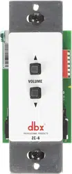
ZC Series Wall Controllers
Zone Controller Wiring
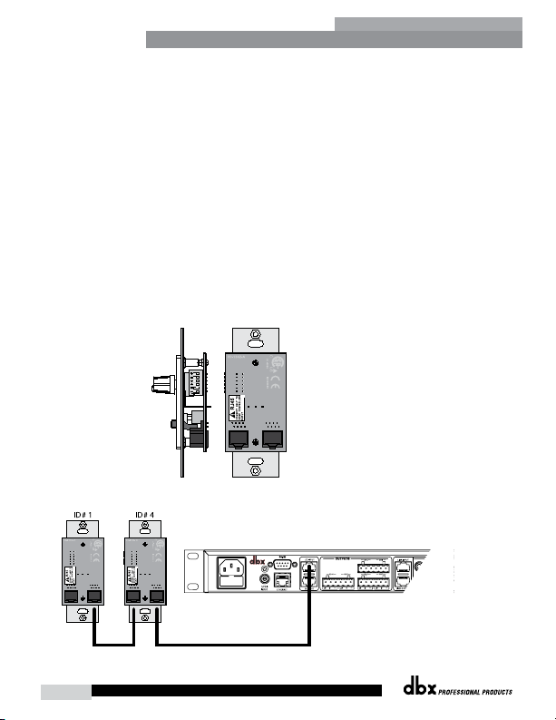
The Zone Controllers, (ZC-1, ZC-2, ZC-3, ZC-4, ZC-6, ZC-7, ZC-8, ZC-9 and ZC-Fire) can be wired serially
or in parallel. To wire in series, each Zone Controller must have an identification or zone number chosen
using the DIP switches on the side of the controller (see diagram A). Each controller must have a unique
number chosen — although there may be multiple Zone Controllers controlling a single zone, or a single Zone
Controller that controls multiple outputs. The Zone Controllers can then be wired together and connected to
the compatible device (e.g., DriveRack
®
220i, 260, ZonePRO
™
, etc.) (see diagram B).
The Zone Controllers may also be wired in parallel with the use of the ZC-BOB. To wire in parallel (home
run cabling), each controller must have a unique identification or number chosen using the DIP switches on
the rear of the panel (see diagram A). To wire in parallel, each controller must be wired into a port of the
ZC-BOB with a connecting wire going to the controlled device (see diagram C). Diagram D shows the typical
wiring for ZC-4 Euroblock connections in which the installer needs to use SPDT (single-pole, double-throw)
switches with one side being connected to 5 volts (+VREF) and the other side to ground (GND). Diagram E
shows the proper way to interface the ZC-Fire to the fire alarm system. Use only the relay/switch closure or
the 5-24V DC inputs. Do not use both inputs at the same time. For information regarding ZC setup, please
see the respective manual for the device that you are setting up.
RS-232
Diagram B
Diagram A
Loading ...
Loading ...
Loading ...