Loading ...
Loading ...
Loading ...
,_ WARNING
Connection of this 265V product to a
branch circuit MUSTbe done by direct
connection to be in compliance with the
National Electric Code. Plugging of this
unit directly into a building mounted
exposed receptacle is not permitted
bycode.
These models must be installed using the
appropriate GE power supply kit for the branch
circuit amperage and the electrical resistance
heater wattage desired. See page 14. One of the
following installation methods must be used:
A Electrical subbase kits are available to provide
a flexible enclosure for direct connection.
Branch Circuit
and Chassis Proper GE Power
Amperage Rating Subbase Kit Supply Kit
15 RAK204E15 RAK5152
15 RAK204E15 RAK5172
20 RAK204E20 RAK5202
30 RAK204E30 RAK5302
The instructions provided with the selected
subbase kit must be carefldly followed. It is
the responsibility of the installer to ensure
that connection of components is done in
accordance with these instructions and all
electrical codes.
B For direct connection to branch circuit wiring
inside the provided junction box without using
a subbase kit, the cord is to be cut and the wire
ends stripped and connected as follows.
Steps for preparing cordset for direct connection:
1 Remove the junction box cover by taking out
the fiont four screws.
2
Junction
box cover
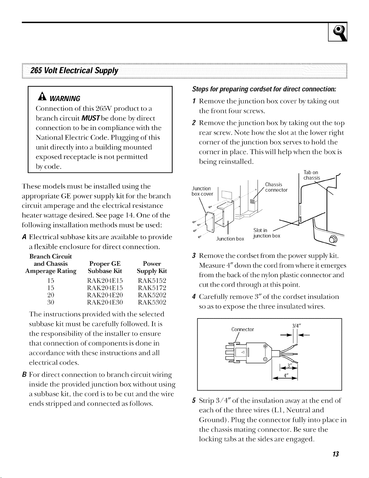
Remove the junction box by taking out the top
rear screw. Note how the slot at the lower right
corner of the junction box serves to hold the
corner in place. This will help when the box is
being reinstalled.
Tabon
I
_h_,_i_ I,-""'_ .,.....3
,ot,ni
Junction box junction box
3 Remove the cordset fiom the power supply kit.
Measure 4" down the cord fiom where it emerges
fiom the back of the wlon plastic connector and
cut the cord through at this point.
4 Carefldly remove 3" of the cordset insulation
so as to expose the three insulated wires.
3/4"
CTnect°r _
Strip 3/4" of the insulation away at the end of
each of the three wires (L1, Neutral and
Ground). Plug the connector fidly into place in
the chassis mating connector. Be sure the
locking tabs at the sides are engaged.
13
Loading ...
Loading ...
Loading ...