*9001468173*
,&$31%
/5&$3%
Ú ,QVWDOODWLRQLQVWUXFWLRQV
[
[
[
$
%
PLQ
PP
PLQ
PLQ
[
[
[
[
[
[
[
[ [
[
[
[
en
Ú
,QVWDOODWLRQLQVWUXFWLRQV
: ,PSRUWDQWVDIHW\LQIRUPDWLRQ
5HDGWKHVHLQVWUXFWLRQVFDUHIXOO\2QO\WKHQZLOO\RXEHDEOHWR
RSHUDWH\RXUDSSOLDQFHVDIHO\DQGFRUUHFWO\5HWDLQWKHLQVWUXFWLRQ
PDQXDODQGLQVWDOODWLRQLQVWUXFWLRQVIRUIXWXUHXVHRUIRU
VXEVHTXHQWRZQHUV
&KHFN WKH DSSOLDQFH IRU GDPDJH DIWHU XQSDFNLQJ LW 'R QRW FRQQHFW
WKHDSSOLDQFHLILWKDVEHHQGDPDJHGLQWUDQVSRUW
7KHDSSOLDQFHFDQRQO\EHXVHGVDIHO\LILWLVFRUUHFWO\LQVWDOOHG
DFFRUGLQJ WR WKH VDIHW\ LQVWUXFWLRQV 7KH LQVWDOOHU LV UHVSRQVLEOH IRU
HQVXULQJWKDWWKHDSSOLDQFHZRUNVSHUIHFWO\DWLWVLQVWDOODWLRQ
ORFDWLRQ
7KHZLGWKRIWKHH[WUDFWRUKRRGPXVWFRUUHVSRQGDWOHDVWZLWKWKH
ZLGWKRIWKHKRE
)RU WKH LQVWDOODWLRQ REVHUYH WKH FXUUHQWO\ YDOLG EXLOGLQJ UHJXODWLRQV
DQGWKHUHJXODWLRQVRIWKHORFDOHOHFWULFLW\DQGJDVVXSSOLHUV
:KHQ FRQYH\LQJ WKH H[KDXVW DLU RIILFLDO DQG OHJDO UHJXODWLRQV HJ
VWDWHEXLOGLQJUHJXODWLRQVPXVWEHIROORZHG
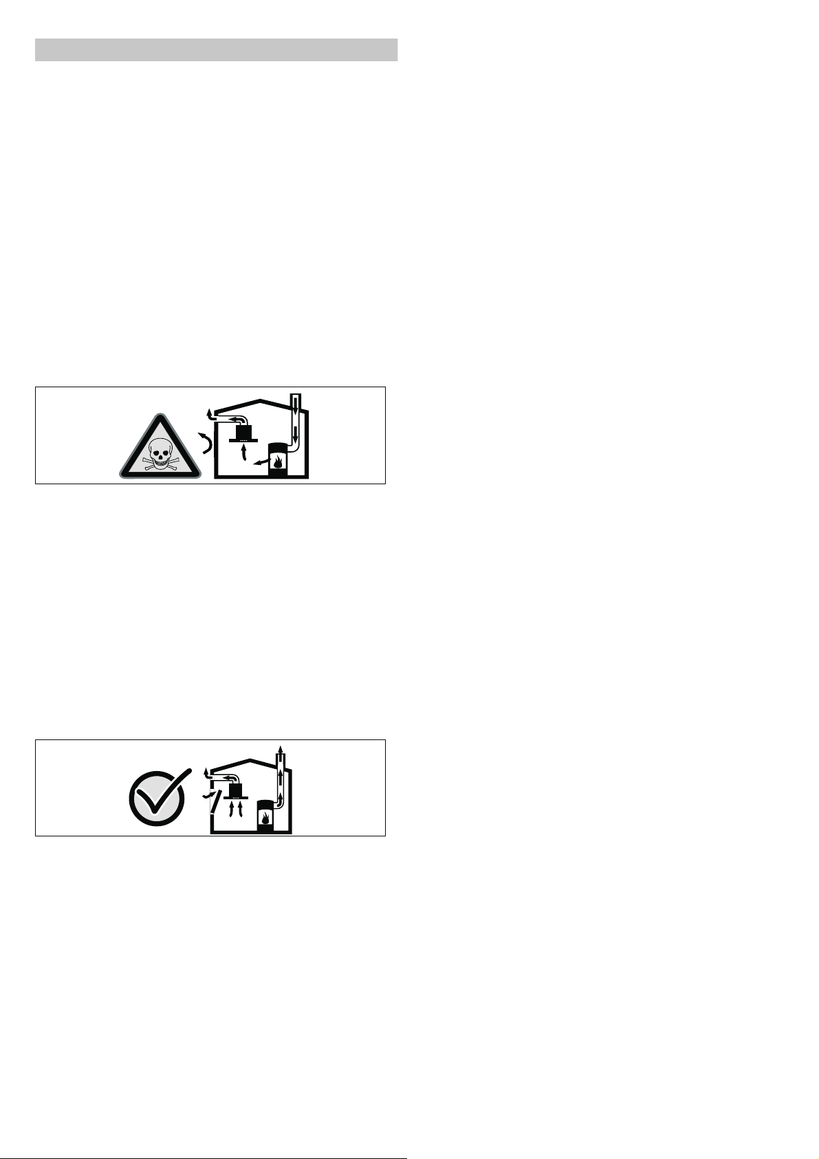
'DQJHURIGHDWK
5LVNRISRLVRQLQJIURPIOXHJDVHVWKDWDUHGUDZQEDFNLQ
$OZD\VHQVXUHDGHTXDWHIUHVKDLULQWKHURRPLIWKHDSSOLDQFHLV
EHLQJRSHUDWHGLQH[KDXVWDLUPRGHDWWKHVDPHWLPHDVURRPDLU
GHSHQGHQWKHDWSURGXFLQJDSSOLDQFHLVEHLQJRSHUDWHG
5RRPDLUGHSHQGHQWKHDWSURGXFLQJDSSOLDQFHVHJJDVRLO
ZRRGRUFRDORSHUDWHGKHDWHUVFRQWLQXRXVIORZKHDWHUVRUZDWHU
KHDWHUVREWDLQFRPEXVWLRQDLUIURPWKHURRPLQZKLFKWKH\DUH
LQVWDOOHGDQGGLVFKDUJHWKHH[KDXVWJDVHVLQWRWKHRSHQDLU
WKURXJKDQH[KDXVWJDVV\VWHPHJDFKLPQH\
,Q FRPELQDWLRQ ZLWK DQ DFWLYDWHG YDSRXU H[WUDFWRU KRRG URRP DLU LV
H[WUDFWHGIURPWKHNLWFKHQDQGQHLJKERXULQJURRPVDSDUWLDO
YDFXXPLVSURGXFHGLIQRWHQRXJKIUHVKDLULVVXSSOLHG7R[LF
JDVHVIURPWKHFKLPQH\RUWKHH[WUDFWLRQVKDIWDUHVXFNHGEDFN
LQWRWKHOLYLQJVSDFH
■ $GHTXDWHLQFRPLQJDLUPXVWWKHUHIRUHDOZD\VEHHQVXUHG
■ $QLQFRPLQJH[KDXVWDLUZDOOER[DORQHZLOOQRWHQVXUH
FRPSOLDQFHZLWKWKHOLPLW
6DIHRSHUDWLRQLVSRVVLEOHRQO\ZKHQWKHSDUWLDOYDFXXPLQWKH
SODFHZKHUHWKHKHDWSURGXFLQJDSSOLDQFHLVLQVWDOOHGGRHVQRW
H[FHHGĂ3DĂPEDU7KLVFDQEHDFKLHYHGZKHQWKHDLU
QHHGHGIRUFRPEXVWLRQLVDEOHWRHQWHUWKURXJKRSHQLQJVWKDW
FDQQRWEHVHDOHGIRUH[DPSOHLQGRRUVZLQGRZVLQFRPLQJ
H[KDXVWDLUZDOOER[HVRUE\RWKHUWHFKQLFDOPHDQV
,Q DQ\ FDVH FRQVXOW \RXU UHVSRQVLEOH 0DVWHU &KLPQH\ 6ZHHS +H
LVDEOHWRDVVHVVWKHKRXVHVHQWLUHYHQWLODWLRQVHWXSDQGZLOO
VXJJHVWWKHVXLWDEOHYHQWLODWLRQPHDVXUHVWR\RX
8QUHVWULFWHGRSHUDWLRQLVSRVVLEOHLIWKHYDSRXUH[WUDFWRUKRRGLV
RSHUDWHGH[FOXVLYHO\LQWKHFLUFXODWLQJDLUPRGH
5LVNRIGHDWK
5LVNRISRLVRQLQJIURPIOXHJDVHVWKDWDUHGUDZQEDFNLQ7KH
H[KDXVWDLUPXVWQRWEHFRQYH\HGLQWRDIXQFWLRQLQJVPRNHRU
H[KDXVWJDVIOXHRULQWRDVKDIWZKLFKLVXVHGWRYHQWLODWH
LQVWDOODWLRQURRPVWKDWFRQWDLQKHDWLQJDSSOLDQFHV,IWKHH[KDXVW
DLU LV WR EH FRQYH\HG LQWR D QRQIXQFWLRQLQJ VPRNH RU H[KDXVW JDV
IOXH\RXPXVWREWDLQWKHFRQVHQWRIWKHKHDWLQJHQJLQHHU
UHVSRQVLEOH
'DQJHURIVXIIRFDWLRQ
3DFNDJLQJPDWHULDOLVGDQJHURXVWRFKLOGUHQ1HYHUDOORZFKLOGUHQ
WRSOD\ZLWKSDFNDJLQJPDWHULDO
5LVNRIHOHFWULFVKRFN
■ &RPSRQHQWV LQVLGH WKH DSSOLDQFH PD\ KDYH VKDUS HGJHV 7KHVH
PD\GDPDJHWKHFRQQHFWLQJFDEOH'RQRWNLQNRUSLQFKWKH
FRQQHFWLQJFDEOHGXULQJLQVWDOODWLRQ
5LVNRIHOHFWULFVKRFN
■ ,WPXVWDOZD\VEHSRVVLEOHWRGLVFRQQHFWWKHDSSOLDQFHIURPWKH
HOHFWULFLW\VXSSO\7KHDSSOLDQFHPXVWRQO\EHFRQQHFWHGWRD
SURWHFWLYHFRQWDFWVRFNHWWKDWKDVEHHQFRUUHFWO\LQVWDOOHG
7KHPDLQVSOXJRIWKHPDLQVSRZHUFDEOHPXVWEHHDVLO\
DFFHVVLEOHDIWHULQVWDOODWLRQRIWKHDSSOLDQFH,IWKLVLVQRW
SRVVLEOHDQDOOSROHLVRODWLQJVZLWFKPXVWEHLQWHJUDWHGLQWRWKH
SHUPDQHQWHOHFWULFDOLQVWDOODWLRQDFFRUGLQJWRWKHFRQGLWLRQVRI
RYHUYROWDJHFDWHJRU\,,,DQGDFFRUGLQJWRWKHLQVWDOODWLRQ
UHJXODWLRQV
7KHSHUPDQHQWHOHFWULFDOLQVWDOODWLRQPXVWRQO\EHZLUHGE\D
SURIHVVLRQDOHOHFWULFLDQ:HUHFRPPHQGLQVWDOOLQJDUHVLGXDO
FXUUHQWFLUFXLWEUHDNHU5&&%LQWKHDSSOLDQFHVSRZHUVXSSO\
FLUFXLW
5LVNRIILUH
■ *UHDVH GHSRVLWV LQ WKH JUHDVH ILOWHU PD\ FDWFK ILUH 7KH VSHFLILHG
VDIHW\GLVWDQFHVPXVWEHREVHUYHGLQRUGHUWRSUHYHQWDQ
DFFXPXODWLRQRIKHDW2EVHUYHWKHVSHFLILFDWLRQVIRU\RXU
FRRNLQJDSSOLDQFH,IJDVEXUQHUVDQGHOHFWULFKRWSODWHVDUH
RSHUDWHGWRJHWKHUWKHODUJHVWVSHFLILHGGLVWDQFHDSSOLHV
5LVNRIILUH
■ *UHDVHGHSRVLWVLQWKHJUHDVHILOWHUPD\FDWFKILUH1HYHUZRUN
ZLWKQDNHGIODPHVFORVHWRWKHDSSOLDQFHHJIODPEpLQJ'R
QRWLQVWDOOWKHDSSOLDQFHQHDUDKHDWSURGXFLQJDSSOLDQFHIRU
VROLGIXHOHJZRRGRUFRDOXQOHVVDFORVHGQRQUHPRYDEOH
FRYHULVDYDLODEOH7KHUHPXVWEHQRIO\LQJVSDUNV
5LVNRILQMXU\
■ &RPSRQHQWV LQVLGH WKH DSSOLDQFH PD\ KDYH VKDUS HGJHV :HDU
SURWHFWLYHJORYHV
5LVNRILQMXU\
■ 7KH DSSOLDQFH PD\ IDOO GRZQ LI LW KDV QRW EHHQ SURSHUO\ IDVWHQHG
LQSODFH$OOIDVWHQLQJFRPSRQHQWVPXVWEHIL[HGILUPO\DQG
VHFXUHO\
5LVNRILQMXU\
■ &KDQJHVWRWKHHOHFWULFDORUPHFKDQLFDODVVHPEO\DUH
GDQJHURXVDQGPD\OHDGWRPDOIXQFWLRQV'RQRWPDNHDQ\
FKDQJHVWRWKHHOHFWULFDORUPHFKDQLFDODVVHPEO\
5LVNRILQMXU\
■ 7KHDSSOLDQFHLVYHU\KHDY\7KHDSSOLDQFHPXVWQRWEHILWWHG
GLUHFWO\RQWRSODVWHUERDUGRUVLPLODUOLJKWZHLJKWPDWHULDOV7R
HQVXUHFRUUHFWLQVWDOODWLRQ\RXPXVWXVHDPDWHULDOZKLFKLV
VXIILFLHQWO\VWDEOHDQGVXLWDEOHIRUERWKWKHVWUXFWXUDOFRQGLWLRQV
DQGWKHZHLJKWRIWKHDSSOLDQFH
*HQHUDOLQIRUPDWLRQ
7KHVXUIDFHVRIWKHDSSOLDQFHDUHHDVLO\GDPDJHG$YRLG
GDPDJLQJWKHPGXULQJLQVWDOODWLRQ
([KDXVWDLUPRGH
1RWH 7KHDLUPXVWQRWEHGLVFKDUJHGLQWRDIOXHWKDWLVXVHGIRU
H[KDXVWLQJIXPHVIURPDSSOLDQFHVEXUQLQJJDVRURWKHUIXHOVQRW
DSSOLFDEOHWRDSSOLDQFHVWKDWRQO\GLVFKDUJHWKHDLUEDFNLQWRWKH
URRP
■ %HIRUHFRQYH\LQJWKHH[KDXVWDLULQWRDQRQIXQFWLRQLQJVPRNH
RUH[KDXVWJDVIOXHREWDLQWKHFRQVHQWRIWKHKHDWLQJHQJLQHHU
UHVSRQVLEOH
■ ,I WKH H[KDXVW DLU LV FRQYH\HG WKURXJK WKH RXWHU ZDOO D WHOHVFRSLF
ZDOOER[VKRXOGEHXVHG
([KDXVWGXFW
1RWH 7KHDSSOLDQFHPDQXIDFWXUHUGRHVQRWSURYLGHDQ\ZDUUDQW\
IRUIDXOWVDWWULEXWDEOHWRWKHSLSHVHFWLRQ
■ 7KH DSSOLDQFH DFKLHYHV LWV RSWLPXP SHUIRUPDQFH E\ PHDQV RI D
VKRUWVWUDLJKWH[KDXVWDLUSLSHDQGDVODUJHDSLSHGLDPHWHUDV
SRVVLEOH
■ $V D UHVXOW RI ORQJ URXJK H[KDXVW DLU SLSHV PDQ\ SLSH EHQGV RU
SLSHGLDPHWHUVWKDWDUHVPDOOHUWKDQĂPPWKHRSWLPXP
H[WUDFWLRQSHUIRUPDQFHLVQRWDFKLHYHGDQGIDQQRLVHLV
LQFUHDVHG
■ 7KH SLSHV RU KRVHV IRU OD\LQJ WKH H[KDXVW DLU OLQH PXVW FRQVLVW RI
QRQFRPEXVWLEOHPDWHULDO
■ ,I WKH H[KDXVW DLU LV FRQYH\HG WKURXJK WKH RXWHU ZDOO D WHOHVFRSLF
ZDOOER[VKRXOGEHXVHG
5LVNRIGDPDJHIURPUHWXUQLQJFRQGHQVDWH,QVWDOOWKHH[KDXVW
GXFW LQ VXFK D ZD\ WKDW LW IDOOV DZD\ IURP WKH DSSOLDQFH VOLJKWO\
VORSH
5RXQGSLSHV
$QLQQHUGLDPHWHURIĂPPEXWDWOHDVWĂPPLV
UHFRPPHQGHG

)ODWGXFWV
7KHLQQHUFURVVVHFWLRQPXVWFRUUHVSRQGWRWKHGLDPHWHURIWKH
URXQGSLSHV
GLDĂPPFDĂFP
GLDĂPPFDĂFP
■ )ODWGXFWVVKRXOGKDYHQRVKDUSGHIOHFWLRQV
■ 8VHVHDOLQJVWULSIRUGHYLDWLQJSLSHGLDPHWHUV
&LUFXODWLQJDLUPRGH
1RWH 7KHDSSOLDQFHPXVWRQO\EHRSHUDWHGZKHQLWLVVHFXUHO\
LQVWDOOHGDQGWKHSLSHZRUNLVFRQQHFWHG
(OHFWULFDOFRQQHFWLRQ
: 5LVNRIHOHFWULFVKRFN
&RPSRQHQWVLQVLGHWKHDSSOLDQFHPD\KDYHVKDUSHGJHV7KHVH
PD\GDPDJHWKHFRQQHFWLQJFDEOH'RQRWNLQNRUSLQFKWKH
FRQQHFWLQJFDEOHGXULQJLQVWDOODWLRQ
7KHUHTXLUHGFRQQHFWLRQGDWDFDQEHIRXQGRQWKHUDWLQJSODWH
LQVLGHWKHDSSOLDQFHWRGRWKLVUHPRYHWKHPHWDOPHVKJUHDVH
ILOWHU
7KLVDSSOLDQFHFRPSOLHVZLWKWKH(&LQWHUIHUHQFHVXSSUHVVLRQ
UHJXODWLRQV
7KLVDSSOLDQFHPD\EHFRQQHFWHGWRDFRUUHFWO\LQVWDOOHGHDUWKHG
VRFNHWRQO\
$WWDFKWKHHDUWKHGVRFNHWSUHIHUDEO\LQVLGHWKHIOXHGXFW
■ 7KHHDUWKHGVRFNHWVKRXOGEHFRQQHFWHGYLDLWVRZQFLUFXLW
■ ,I WKH HDUWKHG VRFNHW LV QR ORQJHU DFFHVVLEOH IROORZLQJ LQVWDOODWLRQ
RIWKHDSSOLDQFHDGLVFRQQHFWHUPXVWEHILWWHGDVIRUD
SHUPDQHQWFRQQHFWLRQ
,I D SHUPDQHQW FRQQHFWLRQ LV UHTXLUHG WKH LQVWDOODWLRQ PXVW IHDWXUH
DQDOOSROHGLVFRQQHFWHUFLUFXLWEUHDNHUVIXVHVDQGFRQWDFWRUV
ZLWK D PLQ ĂPP FRQWDFW RSHQLQJ 7KH SHUPDQHQW FRQQHFWLRQ PD\
EHLQVWDOOHGE\DQHOHFWULFLDQRQO\
,QVWDOODWLRQSUHSDUDWLRQ
&KHFNLQJWKHFHLOLQJ
■ 7KH FHLOLQJ PXVW EH IODW KRUL]RQWDO DQG DGHTXDWHO\ ORDGEHDULQJ
■ 7KHPD[LPXPZHLJKWRIWKHH[WUDFWRUKRRGLV NJ
■ 7KHFRRNLQJYDSRXUVDUHPRUHGLIILFXOWWRGUDZLQWKHIXUWKHU
DZD\WKH\DUHIURPWKHKRE:HUHFRPPHQGDGLVWDQFHRIDW
OHDVWĂPPDQGDPD[LPXPRIĂPP
$SSOLDQFHGLPHQVLRQVDQGVDIHW\FOHDUDQFHV
■ 2EVHUYHWKHDSSOLDQFHVGLPHQVLRQV )LJ $
7KH SRZHU OHYHOV ZHUH PHDVXUHG LQ WKH EXLOWLQ DV GHOLYHUHG ,I WKH
LQVWDOODWLRQSRVLWLRQVFKDQJHWKHSRZHUOHYHOVPD\YDU\
■ &RPSO\ZLWKWKHVDIHW\FOHDUDQFHV )LJ %
,I WKH LQVWDOODWLRQ LQVWUXFWLRQV IRU WKH JDV FRRNLQJ DSSOLDQFH VSHFLI\
D GLIIHUHQW GLVWDQFH WKH ODUJHU RI WKH WZR PXVW DOZD\V EH SURYLGHG
IRU
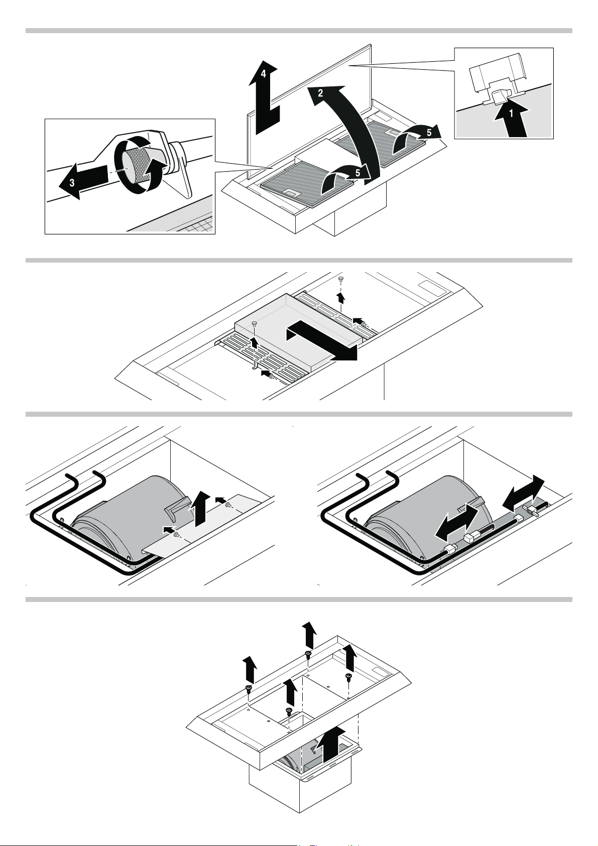
3UHSDULQJWKHDSSOLDQFH
3XVK WKH ORFNLQJ PHFKDQLVP WRJHWKHU ZLWK WZR KDQGV WDNH KROG
RIWKHILOWHUFRYHUDQGRSHQLW )LJ
5HPRYHWKHILOWHUFRYHU )LJ
5HPRYHWKHPHWDOJUHDVHILOWHU )LJ
5HPRYHWKHPRWRUFRYHU )LJ
5HPRYHWKHFDEOHFRYHU )LJ
/RRVHQ ERWK SOXJDQGVRFNHW FRQQHFWLRQV DQG UHOHDVH WKH FDEOHV
IURPWKHFDEOHKROGHUV )LJ
5HPRYHWKHYLHZIUDPH )LJ
5HPRYHWKHPRWRU )LJ
'LVFRQQHFWWKHSRZHUVXSSO\IRUWKHPRWRU )LJ
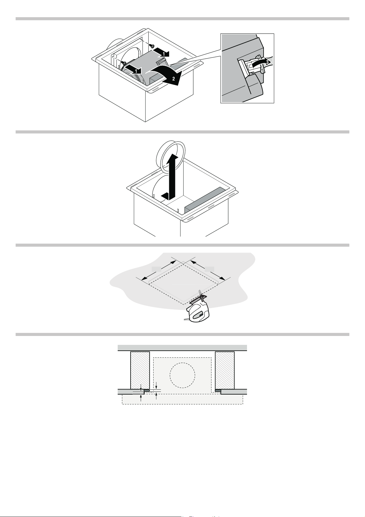
5HPRYHWKHDLUSLSHFRQQHFWRU )LJ
3UHSDULQJWKHFHLOLQJ
7KHFHLOLQJPXVWEHKHDWUHVLVWDQWXSWR&7KHFHLOLQJPXVW
VWLOOEHVWXUG\DIWHUWKHFXWRXWVKDYHEHHQPDGH
$IWHUPDNLQJWKHFXWRXWVUHPRYHDQ\VKDYLQJV
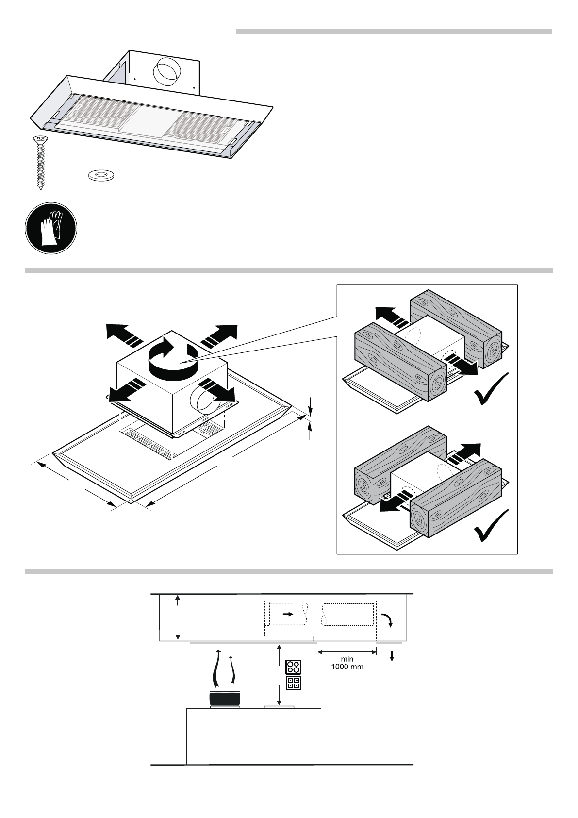
0DNHWKHFXWRXWLQWKHFHLOLQJ )LJ
,IQHFHVVDU\FRPSHQVDWHIRUWKHFHLOLQJWKLFNQHVVE\ĂPPE\
SODFLQJZRRGXQGHUQHDWK )LJ
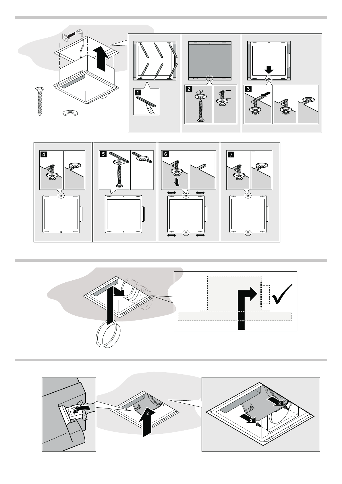
,QVWDOOLQJWKHDSSOLDQFH
6ZLWFKRIIWKHFLUFXLWEUHDNHULQWKHIXVHER[
,QVHUWWKHPRWRUEORFNLQWKHFHLOLQJ )LJ
$OLJQWKHPRWRUEORFNPDUNWKHGULOOKROHVDQGVHWWKHPRWRU
EORFNGRZQDJDLQ )LJ
6FUHZLQRQHRIWKHWZRPLGGOHVFUHZVEXWGRQRWVFUHZLWLQ
FRPSOHWHO\ )LJ
3OXJWKHPDLQVSOXJLQWRWKHHDUWKHGVRFNHW )LJ
+RRNWKHPRWRUEORFNLQWRWKHFHQWUDOVFUHZDQGWLJKWHQWKH
VFUHZ )LJ
7LJKWHQWKHVHFRQGFHQWUDOVFUHZ )LJ
6FUHZLQWKHUHPDLQLQJIRXUVFUHZVORRVHO\GRQRWWLJKWHQWKHP
IXOO\ )LJ
/RRVHQWKHWZRFHQWUDOVFUHZVDJDLQ )LJ
$OLJQWKHPRWRUEORFNDQGWLJKWHQDOORIWKHVFUHZV )LJ
&RQQHFWWKHH[KDXVWDLUSLSH
)LWWKHDLUSLSHFRQQHFWRU )LJ
,QVHUWWKHSRZHUFRUGLQWRWKHPRWRU )LJ
,QVHUW WKH PRWRU LQ WKH PRWRU EORFN DQG VFUHZ LQ SODFH )LJ
6HFXUH WKH VFUHZ IRU WKH HORQJDWHG KROH LQ WKH YLHZ IUDPH RQ WKH
PRWRUEORFNEXWGRQRWVFUHZLWLQFRPSOHWHO\ )LJ
+RRNWKHYLHZIUDPHRQWRWKHHORQJDWHGKROHDQGWLJKWHQDOORI
WKHVFUHZV )LJ
,QVHUWERWKSOXJWKHSOXJDQGVRFNHWFRQQHFWLRQVDQGKRRNRQ
WKHFDEOHV )LJ
)LWWKHFDEOHFRYHU )LJ
)LWWKHPRWRUFRYHU )LJ
)LWWKHPHWDOJUHDVHILOWHU )LJ
)LWWKHILOWHUFRYHU )LJ
&ORVHWKHILOWHUFRYHUDQGHQJDJHWKHORFN )LJ
6ZLWFKWKHFLUFXLWEUHDNHULQWKHIXVHER[EDFNRQ
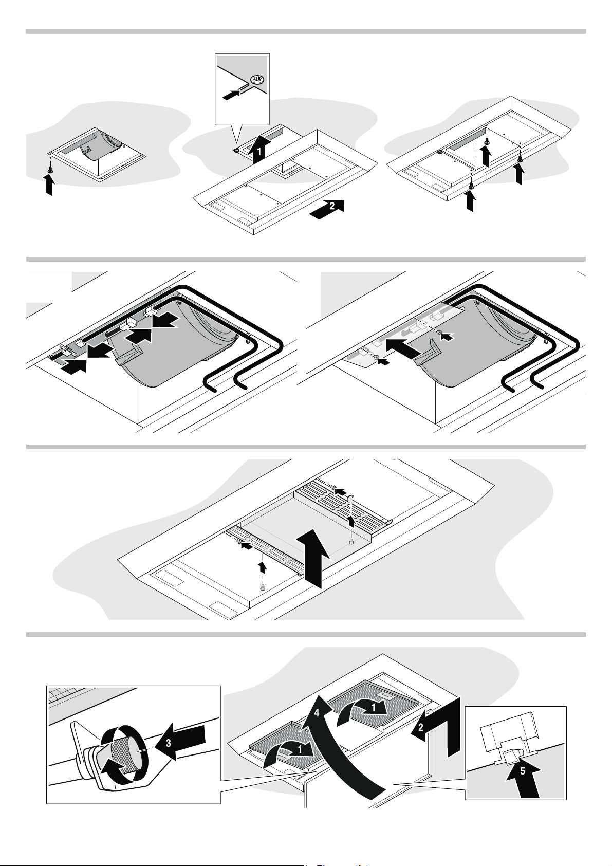
5HPRYLQJWKHDSSOLDQFH
6ZLWFKRIIWKHFLUFXLWEUHDNHU
2SHQDQGUHPRYHWKHILOWHUFRYHU
5HPRYHWKHPHWDOJUHDVHILOWHU
5HPRYHWKHPRWRUFRYHU
'LVFRQQHFWWKHSRZHUFRQQHFWLRQVEHWZHHQWKHYLHZIUDPHDQG
PRWRU
5HPRYHWKHYLHZIUDPH
5HPRYHWKHPRWRU
5HPRYHWKHH[KDXVWSLSHIURPWKHDLUSLSHFRQQHFWRU
5HPRYHWKHPRWRUEORFN
'LVFRQQHFWWKHDSSOLDQFHIURPWKHSRZHUVXSSO\